EP1557598A2 - Float valve assembly for battery - Google Patents
Float valve assembly for battery Download PDFInfo
- Publication number
- EP1557598A2 EP1557598A2 EP20050000996 EP05000996A EP1557598A2 EP 1557598 A2 EP1557598 A2 EP 1557598A2 EP 20050000996 EP20050000996 EP 20050000996 EP 05000996 A EP05000996 A EP 05000996A EP 1557598 A2 EP1557598 A2 EP 1557598A2
- Authority
- EP
- European Patent Office
- Prior art keywords
- valve
- cell
- housing
- valve assembly
- chamber
- Prior art date
- Legal status (The legal status is an assumption and is not a legal conclusion. Google has not performed a legal analysis and makes no representation as to the accuracy of the status listed.)
- Withdrawn
Links
- XLYOFNOQVPJJNP-UHFFFAOYSA-N water Substances O XLYOFNOQVPJJNP-UHFFFAOYSA-N 0.000 claims abstract description 83
- 239000003792 electrolyte Substances 0.000 claims abstract description 63
- 239000007789 gas Substances 0.000 claims abstract description 39
- 239000001301 oxygen Substances 0.000 claims abstract description 34
- 229910052760 oxygen Inorganic materials 0.000 claims abstract description 34
- 238000004880 explosion Methods 0.000 claims abstract description 30
- 238000010791 quenching Methods 0.000 claims abstract description 21
- 230000007246 mechanism Effects 0.000 claims abstract description 17
- 230000004044 response Effects 0.000 claims abstract description 8
- 238000013022 venting Methods 0.000 claims abstract description 7
- 239000012530 fluid Substances 0.000 claims description 38
- 238000004891 communication Methods 0.000 claims description 32
- 239000011148 porous material Substances 0.000 claims description 8
- 238000000429 assembly Methods 0.000 claims description 6
- 230000000712 assembly Effects 0.000 claims description 6
- 239000000463 material Substances 0.000 claims description 6
- 238000007373 indentation Methods 0.000 claims description 4
- 239000006260 foam Substances 0.000 claims 1
- UFHFLCQGNIYNRP-UHFFFAOYSA-N Hydrogen Chemical compound [H][H] UFHFLCQGNIYNRP-UHFFFAOYSA-N 0.000 description 10
- QVGXLLKOCUKJST-UHFFFAOYSA-N atomic oxygen Chemical compound [O] QVGXLLKOCUKJST-UHFFFAOYSA-N 0.000 description 7
- 239000001257 hydrogen Substances 0.000 description 6
- 229910052739 hydrogen Inorganic materials 0.000 description 6
- 238000005868 electrolysis reaction Methods 0.000 description 3
- 230000000750 progressive effect Effects 0.000 description 3
- IJGRMHOSHXDMSA-UHFFFAOYSA-N Atomic nitrogen Chemical compound N#N IJGRMHOSHXDMSA-UHFFFAOYSA-N 0.000 description 2
- QAOWNCQODCNURD-UHFFFAOYSA-N Sulfuric acid Chemical compound OS(O)(=O)=O QAOWNCQODCNURD-UHFFFAOYSA-N 0.000 description 2
- 239000002253 acid Substances 0.000 description 2
- 230000008901 benefit Effects 0.000 description 2
- 238000001816 cooling Methods 0.000 description 2
- 230000000694 effects Effects 0.000 description 2
- 239000008151 electrolyte solution Substances 0.000 description 2
- 238000001704 evaporation Methods 0.000 description 2
- 230000008020 evaporation Effects 0.000 description 2
- VNWKTOKETHGBQD-UHFFFAOYSA-N methane Chemical compound C VNWKTOKETHGBQD-UHFFFAOYSA-N 0.000 description 2
- -1 polyethylene Polymers 0.000 description 2
- 230000000171 quenching effect Effects 0.000 description 2
- 239000004698 Polyethylene Substances 0.000 description 1
- 239000004743 Polypropylene Substances 0.000 description 1
- 229920005830 Polyurethane Foam Polymers 0.000 description 1
- 244000295923 Yucca aloifolia Species 0.000 description 1
- 230000002411 adverse Effects 0.000 description 1
- 238000013459 approach Methods 0.000 description 1
- 230000004888 barrier function Effects 0.000 description 1
- 230000015572 biosynthetic process Effects 0.000 description 1
- 239000000919 ceramic Substances 0.000 description 1
- 238000002485 combustion reaction Methods 0.000 description 1
- 238000012790 confirmation Methods 0.000 description 1
- 238000002474 experimental method Methods 0.000 description 1
- 239000002360 explosive Substances 0.000 description 1
- 238000002844 melting Methods 0.000 description 1
- 230000008018 melting Effects 0.000 description 1
- 238000000034 method Methods 0.000 description 1
- 239000002480 mineral oil Substances 0.000 description 1
- 235000010446 mineral oil Nutrition 0.000 description 1
- 229910052757 nitrogen Inorganic materials 0.000 description 1
- TWNQGVIAIRXVLR-UHFFFAOYSA-N oxo(oxoalumanyloxy)alumane Chemical compound O=[Al]O[Al]=O TWNQGVIAIRXVLR-UHFFFAOYSA-N 0.000 description 1
- 230000000737 periodic effect Effects 0.000 description 1
- 239000004033 plastic Substances 0.000 description 1
- 229920003023 plastic Polymers 0.000 description 1
- 229920000573 polyethylene Polymers 0.000 description 1
- 229920000642 polymer Polymers 0.000 description 1
- 229920001155 polypropylene Polymers 0.000 description 1
- 239000011496 polyurethane foam Substances 0.000 description 1
- 230000008569 process Effects 0.000 description 1
- 239000012858 resilient material Substances 0.000 description 1
- 239000012780 transparent material Substances 0.000 description 1
- 230000000007 visual effect Effects 0.000 description 1
Images


Classifications
-
- F—MECHANICAL ENGINEERING; LIGHTING; HEATING; WEAPONS; BLASTING
- F16—ENGINEERING ELEMENTS AND UNITS; GENERAL MEASURES FOR PRODUCING AND MAINTAINING EFFECTIVE FUNCTIONING OF MACHINES OR INSTALLATIONS; THERMAL INSULATION IN GENERAL
- F16K—VALVES; TAPS; COCKS; ACTUATING-FLOATS; DEVICES FOR VENTING OR AERATING
- F16K24/00—Devices, e.g. valves, for venting or aerating enclosures
- F16K24/04—Devices, e.g. valves, for venting or aerating enclosures for venting only
- F16K24/042—Devices, e.g. valves, for venting or aerating enclosures for venting only actuated by a float
- F16K24/048—Devices, e.g. valves, for venting or aerating enclosures for venting only actuated by a float a transmission element, e.g. arm, being interposed between the float and the valve element, the transmission element following a non-translational, e.g. pivoting or rocking, movement when actuated
-
- F—MECHANICAL ENGINEERING; LIGHTING; HEATING; WEAPONS; BLASTING
- F16—ENGINEERING ELEMENTS AND UNITS; GENERAL MEASURES FOR PRODUCING AND MAINTAINING EFFECTIVE FUNCTIONING OF MACHINES OR INSTALLATIONS; THERMAL INSULATION IN GENERAL
- F16K—VALVES; TAPS; COCKS; ACTUATING-FLOATS; DEVICES FOR VENTING OR AERATING
- F16K31/00—Actuating devices; Operating means; Releasing devices
- F16K31/12—Actuating devices; Operating means; Releasing devices actuated by fluid
- F16K31/18—Actuating devices; Operating means; Releasing devices actuated by fluid actuated by a float
- F16K31/20—Actuating devices; Operating means; Releasing devices actuated by fluid actuated by a float actuating a lift valve
- F16K31/24—Actuating devices; Operating means; Releasing devices actuated by fluid actuated by a float actuating a lift valve with a transmission with parts linked together from a single float to a single valve
- F16K31/26—Actuating devices; Operating means; Releasing devices actuated by fluid actuated by a float actuating a lift valve with a transmission with parts linked together from a single float to a single valve with the valve guided for rectilinear movement and the float attached to a pivoted arm
- F16K31/265—Actuating devices; Operating means; Releasing devices actuated by fluid actuated by a float actuating a lift valve with a transmission with parts linked together from a single float to a single valve with the valve guided for rectilinear movement and the float attached to a pivoted arm with a second lever or toggle between the pivoted arm and the valve
-
- H—ELECTRICITY
- H01—ELECTRIC ELEMENTS
- H01M—PROCESSES OR MEANS, e.g. BATTERIES, FOR THE DIRECT CONVERSION OF CHEMICAL ENERGY INTO ELECTRICAL ENERGY
- H01M10/00—Secondary cells; Manufacture thereof
- H01M10/42—Methods or arrangements for servicing or maintenance of secondary cells or secondary half-cells
- H01M10/4214—Arrangements for moving electrodes or electrolyte
-
- H—ELECTRICITY
- H01—ELECTRIC ELEMENTS
- H01M—PROCESSES OR MEANS, e.g. BATTERIES, FOR THE DIRECT CONVERSION OF CHEMICAL ENERGY INTO ELECTRICAL ENERGY
- H01M50/00—Constructional details or processes of manufacture of the non-active parts of electrochemical cells other than fuel cells, e.g. hybrid cells
- H01M50/30—Arrangements for facilitating escape of gases
- H01M50/383—Flame arresting or ignition-preventing means
-
- H—ELECTRICITY
- H01—ELECTRIC ELEMENTS
- H01M—PROCESSES OR MEANS, e.g. BATTERIES, FOR THE DIRECT CONVERSION OF CHEMICAL ENERGY INTO ELECTRICAL ENERGY
- H01M50/00—Constructional details or processes of manufacture of the non-active parts of electrochemical cells other than fuel cells, e.g. hybrid cells
- H01M50/30—Arrangements for facilitating escape of gases
- H01M50/394—Gas-pervious parts or elements
-
- H—ELECTRICITY
- H01—ELECTRIC ELEMENTS
- H01M—PROCESSES OR MEANS, e.g. BATTERIES, FOR THE DIRECT CONVERSION OF CHEMICAL ENERGY INTO ELECTRICAL ENERGY
- H01M50/00—Constructional details or processes of manufacture of the non-active parts of electrochemical cells other than fuel cells, e.g. hybrid cells
- H01M50/60—Arrangements or processes for filling or topping-up with liquids; Arrangements or processes for draining liquids from casings
- H01M50/609—Arrangements or processes for filling with liquid, e.g. electrolytes
- H01M50/627—Filling ports
- H01M50/636—Closing or sealing filling ports, e.g. using lids
-
- Y—GENERAL TAGGING OF NEW TECHNOLOGICAL DEVELOPMENTS; GENERAL TAGGING OF CROSS-SECTIONAL TECHNOLOGIES SPANNING OVER SEVERAL SECTIONS OF THE IPC; TECHNICAL SUBJECTS COVERED BY FORMER USPC CROSS-REFERENCE ART COLLECTIONS [XRACs] AND DIGESTS
- Y02—TECHNOLOGIES OR APPLICATIONS FOR MITIGATION OR ADAPTATION AGAINST CLIMATE CHANGE
- Y02E—REDUCTION OF GREENHOUSE GAS [GHG] EMISSIONS, RELATED TO ENERGY GENERATION, TRANSMISSION OR DISTRIBUTION
- Y02E60/00—Enabling technologies; Technologies with a potential or indirect contribution to GHG emissions mitigation
- Y02E60/10—Energy storage using batteries
-
- Y—GENERAL TAGGING OF NEW TECHNOLOGICAL DEVELOPMENTS; GENERAL TAGGING OF CROSS-SECTIONAL TECHNOLOGIES SPANNING OVER SEVERAL SECTIONS OF THE IPC; TECHNICAL SUBJECTS COVERED BY FORMER USPC CROSS-REFERENCE ART COLLECTIONS [XRACs] AND DIGESTS
- Y10—TECHNICAL SUBJECTS COVERED BY FORMER USPC
- Y10T—TECHNICAL SUBJECTS COVERED BY FORMER US CLASSIFICATION
- Y10T137/00—Fluid handling
- Y10T137/7287—Liquid level responsive or maintaining systems
- Y10T137/7358—By float controlled valve
Definitions
- the invention concerns float actuated valves for controlling the flow of water to battery cells for replenishment of aqueous electrolyte.
- Buoyant force exerted by the electrolyte 66 on the buoyant body 64 causes the float 60 to rise in the direction of arrow 73, pivoting arms 56 and 58 upwardly as indicated by arrows 77. Motion of the arms is conveyed to the movable valve member 52 through link member 54, and the valve is closed as indicated by arrow 79, halting the flow of water 71.
Landscapes
- Engineering & Computer Science (AREA)
- General Engineering & Computer Science (AREA)
- Chemical & Material Sciences (AREA)
- Chemical Kinetics & Catalysis (AREA)
- Electrochemistry (AREA)
- General Chemical & Material Sciences (AREA)
- Mechanical Engineering (AREA)
- Manufacturing & Machinery (AREA)
- Filling, Topping-Up Batteries (AREA)
Abstract
Description
- The invention concerns float actuated valves for controlling the flow of water to battery cells for replenishment of aqueous electrolyte.
- Float actuated valves are used to control the flow of water into a cell of a battery for replenishing the aqueous electrolyte that is lost during battery charging. Such batteries typically comprise a casing containing a number of individual cells each holding an electrolyte solution in which plates are immersed. Examples of batteries having an aqueous electrolyte include nickelcadmium batteries or lead-acid type batteries. Oxygen and hydrogen gases are produced during charging as a result of electrolysis of the water. The gases bubble up through the electrolyte, cause splashing of the electrolyte at its free surface within the cells, and accumulate in a gas space above the plates and the electrolyte. The electrolysis causes a loss of water from the electrolyte solution, and as a result, such batteries require periodic replenishment of the lost water.
- Float actuated valves are advantageous because they provide a valve that opens and closes automatically in response to the level of electrolyte within a cell. When the electrolyte level is low, the valve opens to allow water to flow into the cell. The valve closes to halt the flow of water once the desired level of electrolyte is reached. This is accomplished by using a float positioned within the cell to open and close the valve. The float is buoyantly supported by the electrolyte and connected to the valve via an actuating mechanism. When the electrolyte level is low, the float moves downwardly away from the valve and its weight applies a force that acts through the actuating mechanism to open the valve. As water flows into the cell through the open valve, the electrolyte level rises and the float is buoyed upwardly and applies an opposite force to the valve through the mechanism which closes the valve once a desired electrolyte level is reached.
- One weakness of float actuated valves currently in use lies in the mechanism that links the float to the valve. This mechanism typically has several moving parts and is prone to stick or jam over time because it becomes fouled with a sticky tar-like residue formed by sulfuric acid reacting with mineral oil which leaches out of the polyethylene material forming the walls of each cell. The residue is deposited on the mechanism when the hydrogen and oxygen bubbles burst at the free surface of the electrolyte. The bubbles splash the residue, which floats on the free surface, onto the mechanism. The residue fouls the parts, which are typically close toleranced sliding components, and prevents them from moving freely relatively to one another, eventually preventing all movement of the float and locking the valve in a closed or an open position. Actual field experience in Europe and the U.S. indicates that present float valves tend to fail in less than 18 months in high temperature or heavy duty service.
- Another weakness of float valves is their lack of resistance to progressive hydrogen-oxygen explosions traveling between cells. Typically, the cells are connected in series to one another through the conduit that supplies replenishing water. Most of the valve designs currently in use have a water trap in the valve that is intended to prevent a flash path from developing through the conduit between the cells. Unfortunately, the water does not always remain within the trap. It can evaporate, drain out if the battery is tilted or be forced out by gas pressure that develops within each cell during charging.
- Yet another problem associated with current float actuated valves is their lack of a flash arrester for hydrogen gas that vents from the cell to the ambient. Such flash arresters would be effective at preventing a hydrogen-oxygen explosion, but are often not used because they tend to restrict gas flow from the cells which causes a back pressure to develop within the cells. The gases that build up in the cells often find an escape path through the water traps and conduit described above that connect the cells for water replenishment, thus, forming a perfect flash path for a progressive hydrogen-oxygen explosion throughout the cells of the battery.
- There is clearly a need for an improved float actuated valve that addresses the aforementioned weaknesses of float valves currently in use.
- The invention concerns a valve assembly mountable on a battery cell and connectable to a water source for controlling the flow of water from the source to the cell for electrolyte replenishment. The valve assembly comprises a housing sealingly engageable with an opening in the cell. An inlet is positioned in the housing, the inlet being connectable to the water source. A valve is mounted within the housing in fluid communication with the inlet. The valve has a member movable to open it and admit water from the source into the cell, the member also being movable to close the valve and halt the flow of water to the cell. A float is positionable within the cell. The float is buoyantly supportable by the electrolyte and movable relatively to the valve in response to changes in the level of the electrolyte within the cell. First and second elongated arms are arranged in substantially parallel, spaced apart relation within the housing. One end of each arm is pivotally attached to the housing, the other end is pivotally attached to the float. The float pivots the arms upon movement relatively to the valve. A link member connects one of the arms to the movable valve member. The link member moves the valve member upon pivoting of the one arm to open the valve and admit water to the cell when the float moves in a direction away from the valve, indicative of a low electrolyte level. The link member moves the valve member to close the valve and halt water flow to the cell when the float moves toward the valve to a position indicative of an adequate electrolyte level within the cell.
- Preferably, the float valve according to the invention also comprises a baffle plate mounted within the housing and positioned between the arms and the float. The baffle plate protects the arms from the electrolyte splashing within the cell during charging of the cell.
- A flash arrester positioned within the housing between the inlet and the valve may also be included as part of the valve. The flash arrester has a plurality of passageways therethrough adapted to allow water to flow from the inlet to the valve, but the passageways are sized so as to quench a hydrogen-oxygen explosion.
- Preferably, a vent duct is positioned within the housing for providing fluid communication between the cell and the ambient. The vent duct vents hydrogen and oxygen gases from the cell and has a hinged cover with a slot for venting gases to the ambient.
- A flash arrester may be in fluid communication with the vent duct. The flash arrester comprises a porous medium positioned within a chamber located between the vent duct and an outlet. The medium is in spaced relation to a cover enclosing the chamber. The hydrogen and oxygen gases pass from the cell through the medium into the space between the medium and the cover before exiting to the ambient through the outlet. The pores of the medium are sized to quench hydrogen-oxygen combustion and stop it from flashing into and igniting the cell. The space between the medium and the cover allows a controlled mini-explosion to extinguish any flame which could burn on the surface of the medium, melt it and then ignite the cell.
- The invention also includes a battery using one or more valve assemblies and flash arresters as described above.
-
- Figure 1 is a plan view of a battery having float valve assemblies according to the invention;
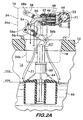
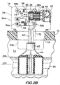
- Figures 2, 2A and 2B are longitudinal sectional views of a float valve assembly taken at line 2-2 of Figure 1;
- Figures 3A and 3B are longitudinal sectional views of a float valve assembly taken at line 3-3 of Figure 1;
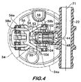
- Figure 4 is a cross-sectional view taken at line 4-4 of Figure 2;
- Figures 5 and 5A are longitudinal sectional views of a portion of the float valve assembly; and
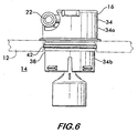
- Figure 6 is an elevational view of an alternate embodiment of a float valve assembly according to the invention.
-
- Figure 1 shows an
aqueous electrolyte battery 10 comprising acasing 12 divided into a plurality ofcells 14, each cell having its ownfloat valve assembly 16 sealingly engaged with avent opening 18 in the cell (see also Figure 2).Float valves 16 are connected in series to one another by afluid conduit 20 that engagestee fittings 22 on each float valve. Theconduit 20 is connectable to awater source 24 which provides water to replenish electrolyte lost from the cells during charging. During water replenishment, eachfloat valve 16 controls the flow of water to its associated cell as described below. The float valves may also be connected to agas conduit 26 in fluid communication with agas discharge outlet 28 on each float valve. The gas discharge outlet allows oxygen and hydrogen gas, generated by electrolysis during charging, to vent from the cells. Thegas conduit 26 conducts the gas away to be discharged to the ambient remotely from thecells 14. Aflash arrester 32, described in detail below, is preferably mounted on thefloat valves 16 and may be connected to thegas conduit 26 using compatible fittings or may vent freely to the ambient. - Figure 2 shows a sectional view of a
float valve assembly 16 according to the invention.Float valve 16 comprises ahousing 34 having anupper portion 34a that houses the valve assembly mechanism, and a lower portion, 34b, that sealingly engages vent opening 18 defined by casing 12 ofcell 14.Lower housing portion 34b is adapted to be compatible with a specific type of vent opening, for example, the quarter-turn bayonet type mount 36 as shown in Figure 2 and found on U.S. batteries, or, as shown in Figure 6, the 35 mm pushfit mount 38, compatible with the German Industry Standard (DIN) and found on European batteries. Float valves compatible with the German standard use an O-ring seal 42 between the valve assembly and the casing to effect a seal and allow the valve assembly to rotate. - In the float valve assembly compatible with the U.S. bayonet mount 36 (see Figure 2), the
lower housing portion 34b has an outwardly bulged section 40 that is flexible and resilient and that snaps under the lugs of the bayonet mount, but allows the valve assembly to rotate within theopening 18. - With reference again to Figure 2, an
inlet 44 is in fluid communication with Tee fitting 22 in the housingupper portion 34a.Inlet 44 leads to achamber 46 which houses aflash arrester 48, described below. Avalve 50 is in fluid communication withchamber 46.Valve 50 comprises amember 52 that is movable between a closed position (shown in Figure 2) and an open position (shown in Figure 2A) to open andclose valve 50 and control the flow of water therethrough. Alink member 54 attachesmovable member 52 to anarm 56.Arm 56 has acounterpart arm 58 and forms a four bar mechanism.Arms first ends upper portion 34a. The second ends 56b and 58b are pivotally attached to afloat 60.Float 60 comprises arod 62 to which thearms buoyant body 64 that is buoyantly supported by theelectrolyte 66 incell 14. -
Float 60 moves up and down in the direction ofarrow 68 in response to the electrolyte level withincell 14. The use of the four bar mechanism formed byarms float 60 is translated into substantially horizontal motion of themovable member 52, as indicated by arrow 70, by thelink member 54 that is pivotally connected toarm 56. It is recognized thatlink member 54 could be connected to eitherarm valve 50. Further, the motion of the movable member need not be horizontal, but could be oriented in other directions as required to open andclose valve 50, which, in this example, is oriented for actuation in a horizontal direction. - Two baffle plates, 72 and 74, divide the
upper housing portion 34a from thelower housing portion 34b.Rod 62 extends throughrespective openings electrolyte 66 and burst at the surface. Further protection against fouling of the mechanism is afforded by positioning it in theupper housing portion 34a as far away from the electrolyte as possible, and preferably above thecell casing 12. - Replenishment of electrolyte is initially described with reference to Figures 1 and 4.
Conduit 20 is attached towater source 24 and water is permitted to flow toTee fittings 22 ofbattery 10. As shown in Figure 4,water 71 enterschamber 46 throughinlet 44 and passes throughflash arrester 48 tovalve 50. If, as shown in Figure 2A, theelectrolyte 66 is at a low level, then the weight offloat 60pivots arms link member 54 towardvalve 50 and moving themovable valve member 52 into an open position.Water 71 flows through thevalve 50, into thelower housing portion 34b and is discharged intocell 14. As the water flows into the cell, the electrolyte level rises until it reaches a desired level, shown in Figure 2B. Buoyant force exerted by theelectrolyte 66 on thebuoyant body 64 causes thefloat 60 to rise in the direction ofarrow 73, pivotingarms arrows 77. Motion of the arms is conveyed to themovable valve member 52 throughlink member 54, and the valve is closed as indicated byarrow 79, halting the flow ofwater 71. - Visual confirmation that the electrolyte is at the desired level in a cell is provided by an
indicator 80 shown in Figures 3A and 3B.Indicator 80 is positioned inupper housing portion 34a and preferably attached to therod 62 offloat 60. Awindow 81, formed of a transparent material through which the indicator may be viewed, is positioned in thesidewall 82 of thehousing 34. It is advantageous to position the window so that theindicator 80 is visible from both the side and the top of the valve assembly. This configuration is convenient when the battery is positioned within a tunnel, as is the case for various forklift trucks, which affords a view of the battery only from the side. The indicator may be a bright fluorescent color so as to be more readily visible throughwindow 81. Being mounted on the float, the indicator moves with it. In a preferred embodiment, when the electrolyte level is low, the indicator is not visible inwindow 81 as shown in Figure 3A. However, when the electrolyte is at the desired level, the indicator is moved upwardly along with thefloat 60, and is visible throughwindow 81 as shown in Figure 3B. - Motion of the
arms close valve 50 as well as to move theindicator 80 is effected by the buoyancy ofbuoyant body 64. In a preferred embodiment, shown in Figure 2, the buoyant body comprises aninverted cup 84 with anopen end 86 that interfaces with theelectrolyte 66. Buoyancy is afforded by air trapped within theinterior space 88 ofcup 84 by the electrolyte. This configuration is preferred to a sealed hollow body, which has a tendency to leak, flood with electrolyte, and lose buoyancy, thereby holding thevalve 50 in an open position regardless of electrolyte level. In an alternate embodiment, shown in Figure 5A, thecup 84 may be filled with abuoyant material 90, such as a low density, closed cell, polyurethane foam. - It is advantageous to make the
buoyant body 64 adjustable on therod 62 so that one valve assembly may be used with cells of various sizes. This is accomplished, as shown in Figure 5, by forming abore 92 through the buoyant body adapted to receiverod 62. Thebody 64 is slidable along therod 62 as indicated byarrow 94. Preferably, a plurality ofindentations 96 are spaced lengthwise along the rod. The indentations cooperate with aprojection 98 positioned within thebore 92 to fix thebody 64 in any one of a number of desired predetermined locations alongrod 62 as indicated in phantom line. This allows the valve assembly to compensate for different sized cells having different electrolyte levels relative to the position of the valve assembly mounted in the vent opening of the casing. Therod 62 and thebuoyant body 64 are preferably made of a flexible, resilient material, such as an acid resistant polymer, to permit easy manual adjustment. - The
valve assembly 16 preferably incorporates two types of flash arresters.Flash arrester 48, shown in Figure 2 and known as an "in line flash arrester", is positioned withinchamber 46 and prevents thefluid conduit 22 from forming a flash path between cells that would otherwise support a progressive hydrogen-oxygen explosion. In the embodiment illustrated in Figure 2, the flash arrester comprises aporous medium 100 withinchamber 46. The medium 100 allows water to flow when thevalve 50 is open, but the pores are sized so as to quench a hydrogen-oxygen explosion. Preferably, the medium comprises a sintered plastic, such as polypropylene. Sintered ceramics, such as aluminum oxide, are also feasible. Nominal pore size is preferably less than about 1/100 of an inch to quench the hydrogen-oxygen explosion. The quenching effect is based upon the same principle as used for methane gas in the Davey lamp. Use of the medium 100 "in line" with thewater inlet 44 provides a safety barrier preventing the propagation of an explosion from cell to cell which cannot be circumvented as long as the medium is in place. Unlike valves that use a water trap, the in line arrester disclosed herein is not adversely affected by gas pressure build up within thecell 14 during charging. - In another embodiment, shown in Figure 4, the in line arrester comprises a
body 102 positioned within thechamber 46. The body has an outer surface 104 that interfaces with the inner surface of thechamber wall 106. A plurality of grooves 108 are formed lengthwise along outer surface 104 ofbody 102. The grooves cooperate with the chamber wall and form passageways between theinlet 44 andvalve 50 allowingwater 71 to flow. The grooves are sized so as to quench a hydrogen-oxygen explosion, and thus prevent the formation of a cell to cell flash path byfluid conduit 20. Grooves 108 are about 1/100 of an inch deep, which is sufficiently small to quench any hydrogen-oxygen explosion. Alternately, the grooves 108 may be positioned in thechamber wall 106 and the outer surface 104 ofbody 102 may be smooth. The grooves in the chamber wall cooperate with the smooth outer surface ofbody 102 to form the flame quenching passageways betweeninlet 44 andvalve 50. - Preferably, as shown in Figures 3A and 3b, a
vent duct 110 is positioned withinhousing 34 and provides fluid communication betweencell 14 and the ambient.Vent duct 110 may be closed with a hingedcover 112 having aslot 113 for venting gases to the ambient. Thevent duct 110 may also be used in conjunction with agas conduit 26 as shown in Figure 1, or aflash arrester 32, as described below. - Figure 3B illustrates, in phantom line, a flash arrester embodiment, 32.
Arrester 32 is mountable either on top or on the side of thevalve assembly 16 and comprises achamber 116 in fluid communication withvent duct 110 through atube 118 extending from the chamber.Tube 118 may have a seal, such as O-ring 120, that allows the tube to sealingly engage thevent duct 110 and thereby channel any gas from thecell 14 into the chamber. Aporous medium 122 is positioned within thechamber 116. Gases are directed fromtube 118 into the medium and diffuse therethrough. Pores in the medium are sized to quench a hydrogen-oxygen explosion and prevent a flash from enteringcell 14.Chamber 116 has acover 124 that is positioned in spaced relation to the medium 122. Thespace 126 between the medium and the cover is such that it will allow a small controlled explosion that extinguishes any continuous flame and prevent it from melting theflash arresting medium 122.Vent ports 128 incover 124 form gas outlets allowing the gases to escape fromchamber 116 to the ambient. Alternatively, the gas outlet may be provided by a fitting 130 in fluid communication withchamber 116. As shown in Figure 1, fitting 130 is connected to theconduit 26 which allows the hydrogen and oxygen gases to be vented to the ambient remotely from the battery. - Float valve assemblies according to the invention provide distinct advantages over valves currently in use for battery watering in that the four bar mechanism used to actuate the valve in response to motion of the float is not subject to jamming or sticking due to electrolyte residue fouling because it does not have relatively sliding parts and is also protected by a splash baffle. The fluid conduit providing water to the cells cannot form a flash path for a hydrogen-oxygen explosion because there is an in line flash arrester that uses passageways having small dimensions to quench any such explosions.
Additional flash arresters enhance safety during charging by preventing hydrogen-oxygen explosions when gases are vented from the cells. Further advantageous features include a side viewable electrolyte level indicator and an unsinkable float that is adjustable for accommodating different sized cells. The housing is adaptable for use with both U.S. and European batteries. - A further advantageous feature of the present invention is the use of the existing
water supply tubing 20 and thevalve assemblies 16 shown in Figure 1 for evaporative air cooling of the battery cells. Since water filling is a very intermittent operation, seldom carried but more than once a week, the entire water tubing system and the valve assemblies are available for another use most of the time. It is well known that the heat of evaporation of water is 540 kcal/gram, so passing air through thewater tubing 20 into the head space of a battery cell, and thence to atmosphere, increases the evaporation rate of water from the cell electrolyte and thereby cools the cell. The amount of cooling will depend on the amount of water evaporated which, in turn, will depend on the quantity of air flow and the dryness of the air among other factors. - The preferred approach involves forcing lightly compressed atmospheric air, preferably as dry as possible, through the water supply tubing and into each cell of the battery, thereafter venting the now wet air to atmosphere through the existing vent and thereby removing heat from the cell. This process has been shown by experiment to cool the cells appreciably, especially if the air flow is continuous. The compressed air is preferably produced by a pump or pumps mounted on the battery or on the vehicle so that the air flow may operate nearly continuously of necessary. But the pumps may also be mounted on or near . the battery charger and used only during charging. A thermostat, timer or other controls, not shown, may control the air pump or pumps.
- A further benefit of this feature is that, if operated during recharging of the cells, the air flow entering each cell from the water tubing prevents hydrogen gas from entering the water tubing, thereby completely preventing an ignition path in the tubing at all times the pumps are on, even if the cell is slightly pressurized by flash arresters in the vent. The air flow, which is largely non-explosive nitrogen, also dilutes the hydrogen concentration inside the cell head space. Both of these actions improve the safety of the battery to a useful degree.
Claims (32)
- A valve assembly mountable on a battery cell and connectable to a water source for controlling the flow of water from the source to the cell for electrolyte replenishment, said valve assembly comprising:a housing being sealingly engageable with an opening in said cell;an inlet positioned in said housing, said inlet being connectable to said water source;a valve mounted within said housing in fluid communication with said inlet, said valve having a member movable to open said valve and admit water from said source into said cell, said member also being movable to close said valve and halt the flow of water to said cell;a float positionable within said cell, said float being buoyantly supportable by said electrolyte and movable relatively to said valve in response to changes in the level of said electrolyte within said cell;first and second elongated arms arranged in substantially parallel, spaced apart relation within said housing, one end of each arm being pivotally attached to said housing, the other end being pivotally attached to said float to form a four bar mechanism, said float pivoting said arms upon movement relatively to said valve; anda link member connecting one of said arms to said movable valve member, said link member moving said valve member upon pivoting of said one arm to open said valve and admit water to said cell when said float moves in a direction away from said valve indicative of a low electrolyte level, said link member moving said valve member to close said valve and halt water flow to said cell when said float moves toward said valve to a position indicative of an adequate electrolyte level within said cell.
- A valve assembly according to Claim 1, further comprising a flash arrester positioned within said housing between said inlet and said valve, said flash arrester having a plurality of passageways therethrough adapted to allow water to flow from said inlet to said valve, said passageways being sized so as to quench a hydrogen-oxygen explosion.
- A valve assembly according to Claim 2, wherein said flash arrester comprises a porous medium.
- A valve assembly according to Claim 2, wherein said flash arrester comprises:a chamber having a central space defined by a sidewall surrounding said space, said chamber having a first end in fluid communication with said inlet and a second end in fluid communication with said valve; anda body positioned within said chamber, said body having an outer surface interfacing with said sidewall, a plurality of grooves being positioned in said outer surface and extending along said body, said grooves cooperating with said sidewall and forming said passageways allowing water to flow from said inlet to said valve, said grooves being sized so as to quench a hydrogen-oxygen explosion within said chamber.
- A valve assembly according to Claim 2, wherein said flash arrester comprises:a chamber having a central space defined by a sidewall surrounding said space, said chamber having a first end in fluid communication with said inlet and a second end in fluid communication with said valve, a plurality of grooves being positioned lengthwise along said sidewall facing said central space; anda body positioned within said chamber, said body having an outer surface interfacing with said sidewall, said grooves cooperating with said outer surface of said body and forming said passageways allowing water to flow from said inlet to said valve, said grooves being sized so as to quench a hydrogen-oxygen explosion within said chamber.
- A valve assembly according to Claim 1, further comprising:an indicator movably positioned within said housing, said indicator being attached to said float and moving within said housing in response to motion of said float; anda window positioned within a sidewall of said housing, said indicator being visible through said window, the position of said indicator being indicative of the level of electrolyte in said cell.
- A valve assembly according to Claim 1, wherein said housing includes a lower portion having a flexible, resilient outwardly bulged section adapted to fit beneath lugs of a bayonet mount for mounting said valve assembly within said opening.
- A valve assembly according to Claim 1, wherein said housing includes a lower portion having an O-ring extending circumferentially therearound, said O-ring being sealingly engageable with said opening for mounting said valve assembly within said opening.
- A valve assembly according to Claim 1, wherein said float comprises:an elongated rod pivotally attached to said ends of said first and second arms; anda buoyant body mounted on said rod, said buoyant body being slidably movable along said rod for positioning said buoyant body at a plurality of predetermined positions located lengthwise along said rod for accommodating cells having different sizes from one another.
- A valve assembly according to Claim 9, wherein:said rod has a plurality of indentations positioned in spaced relation to one another lengthwise therealong;said buoyant body has a bore therethrough for receiving said rod; anda projection being mounted on said body and extending into said bore, said projection cooperating with said indentations to fix the position of said buoyant body at one of said predetermined positions lengthwise along said rod.
- A valve assembly according to Claim 1, wherein said float comprises a cup having an open end engaging said electrolyte, air being trapped within said cup by said electrolyte providing buoyancy to said float.
- A valve assembly according to Claim 1, wherein said float comprises:a cup having an interior space and an open end engaging said electrolyte; anda buoyant material being positioned within said cup, said buoyant material providing buoyancy to said float, said cup protecting said buoyant material.
- A valve assembly according to Claim 12, wherein said buoyant material comprises closed-cell foam.
- A valve assembly according to Claim 1, further comprising:a vent duct positioned within said housing for providing fluid communication between said cell and the ambient for venting gases from said cell;a flash arrester in fluid communication with said vent duct, said flash arrester comprising:a chamber having a cover and an outlet to the ambient; anda porous medium positioned within said chamber between said vent duct and said outlet, said medium being in spaced relation to said cover, said gases passing from said cell through said medium into said space between said medium and said cover before exiting to the ambient through said outlet, said porous medium having pores sized to quench a hydrogen-oxygen explosion within said chamber.
- A valve assembly according to Claim 14, wherein said flash arrester is mountable on top of said valve assembly.
- A valve assembly according to Claim 14, wherein said flash arrester is mountable on a side of said valve assembly.
- A valve assembly according to Claim 14, further comprising an elongated conduit in fluid communication with said outlet, said conduit extending away from said cell for releasing said gases to the ambient remotely from said cell.
- A battery having a plurality of cells, a valve assembly mounted on each said cell, said valve assemblies being connectable to a water source for controlling the flow of water from the source to the cells for electrolyte replenishment, each said valve assembly comprising:a housing sealingly engaged with an opening in each said cell;an inlet positioned in said housing said inlet being connectable to said water source;a valve mounted within said housing in fluid communication with said inlet, said valve having a member movable to open said valve and admit water from said source into said cell, said member also being movable to close said valve and halt the flow of water to said cell;a float positionable within said cell, said float being buoyantly supportable by said electrolyte and movable relatively to said valve in response to changes in the level of said electrolyte within said cell;first and second elongated arms arranged in substantially parallel, spaced apart relation within said housing, one end of each arm being pivotally attached to said housing, the other end being pivotally attached to said float and forming a four bar mechanism, said float pivoting said arms upon movement relatively to said valve; anda link member connecting one of said arms to said movable valve member, said link member moving said valve member upon pivoting of said one arm to open said valve and admit water to said cell when said float moves in a direction away from said valve indicative of a low electrolyte level, said link member moving said valve member to close said valve and halt water flow to said cell when said float moves toward said valve to a position indicative of an adequate electrolyte level within said cell.
- A battery according to Claim 18, wherein each said valve assembly further comprises a flash arrester positioned within said housing between said inlet and said valve, said flash arrester having a plurality of passageways therethrough adapted to allow water to flow from said inlet to said valve, said passageways being sized so as to quench a hydrogen-oxygen explosion.
- A battery according to Claim 18, wherein each said valve assembly further comprises:a vent duct positioned within said housing for providing fluid communication between said cell and the ambient for venting gases from said cell;a flash arrester in fluid communication with said vent duct, said flash arrester comprising:a chamber having a cover and an outlet to the ambient; anda porous medium positioned within said chamber between said vent duct and said outlet, said medium being in spaced relation to said cover, said gases passing from said cell through said medium into said space between said medium and said cover before exiting to the ambient through said outlet, said porous medium having pores sized to quench a hydrogen-oxygen explosion within said chamber.
- A battery according to Claim 18, further comprising a fluid conduit extending between at least two of said valve inlets, said fluid conduit providing fluid communication between said cells.
- A battery according to Claim 20, further comprising a gas conduit extending between at least two of said outlets, said gas conduit providing fluid communication between said outlets and the ambient for venting gases remotely from said cells.
- A valve assembly mountable on a battery cell and connectable to a water source for controlling the flow of water from the source to the cell for electrolyte replenishment, said valve assembly comprising:a housing being sealingly engageable with an opening in said cell;an inlet positioned in said housing, said inlet being connectable to said water source;a valve mounted within said housing in fluid communication with said inlet, said valve having a member movable to open said valve and admit water from said source into said cell, said member also being movable to close said valve and halt the flow of water to said cell; anda flash arrester positioned within said housing between said inlet and said valve, said flash arrester having a plurality of passageways therethrough adapted to allow water to flow from said inlet to said valve, said passageways being sized so as to quench a hydrogen-oxygen explosion within said housing.
- A valve assembly according to Claim 23, wherein said flash arrester comprises a porous medium.
- A valve assembly according to Claim 23, wherein said flash arrester comprises:a chamber having a central space defined by a sidewall surrounding said space, said chamber having a first end in fluid communication with said inlet and a second end in fluid communication with said valve;a body positioned within said chamber, said body having an outer surface interfacing with said sidewall, a plurality of grooves being positioned in said outer surface and extending along said body, said grooves cooperating with said sidewall and forming said passageways allowing water to flow from said inlet to said valve, said grooves being sized so as to quench a hydrogen-oxygen explosion within said chamber.
- A valve assembly according to Claim 23, wherein said flash arrester comprises:a chamber having a central space defined by a sidewall surrounding said space, said chamber having a first end in fluid communication with said inlet and a second end in fluid communication with said valve, a plurality of grooves being positioned lengthwise along said sidewall facing said central space; anda body positioned within said chamber, said body having an outer surface interfacing with said sidewall, said grooves cooperating with said outer surface of said body and forming said passageways allowing water to flow from said inlet to said valve, said grooves being sized so as to quench a hydrogen-oxygen explosion within said chamber.
- A valve assembly mountable on a battery cell and connectable to a water source for controlling the flow of water from the source to the cell for electrolyte replenishment, said valve assembly comprising:a housing being sealingly engageable with an opening in said cell;an inlet positioned in said housing, said inlet being connectable to said water source;a valve mounted within said housing in fluid communication with said inlet, said valve having a member movable to open said valve and admit water from said source into said cell, said member also being movable to close said valve and halt the flow of water to said cell;a vent duct positioned within said housing and providing fluid communication between said cell and the ambient;a flash arrester mounted on said housing, said flash arrester comprising:a chamber in fluid communication with said vent duct, said chamber having a cover and an outlet to the ambient; anda porous medium positioned within said chamber between said vent duct and said outlet, said gases passing from said cell through said medium and exiting to the ambient through said outlet, said porous medium having pores sized to quench a hydrogen-oxygen explosion within said chamber.
- A valve assembly according to Claim 27, wherein said medium is positioned in spaced relation to said cover to provide a space adapted for extinguishing a continuous flame of a hydrogen-oxygen explosion, said gases passing into said space between said medium and said cover before exiting to the ambient through said outlet.
- A valve assembly according to Claim 27, wherein said flash arrester is mounted on a top of said housing.
- A valve assembly according to Claim 27, wherein said flash arrester is mounted on a side of said housing.
- A flash arrester mountable on a valve assembly of a battery cell, said valve assembly being connectable to a water source for controlling the flow of water from the source to the cell for electrolyte replenishment, said valve assembly including
a vent duct positioned within said housing and providing fluid communication between said cell and the ambient, said flash arrester comprising:a chamber positionable in fluid communication with said vent duct, said chamber having a cover and an outlet to the ambient; anda porous medium positioned within said chamber between said vent duct and said outlet, said gases passing from said cell through said medium and exiting to the ambient through said outlet, said porous medium having pores sized to quench a hydrogen-oxygen explosion within said chamber. - A valve assembly according to Claim 31, wherein said medium is positioned in spaced relation to said cover to provide a space adapted for extinguishing a continuous flame of a hydrogen-oxygen explosion, said gases entering said space between said medium and said cover before exiting to the ambient through said outlet.
Applications Claiming Priority (2)
| Application Number | Priority Date | Filing Date | Title |
|---|---|---|---|
| US53769104P | 2004-01-20 | 2004-01-20 | |
| US537691P | 2004-01-20 |
Publications (2)
| Publication Number | Publication Date |
|---|---|
| EP1557598A2 true EP1557598A2 (en) | 2005-07-27 |
| EP1557598A3 EP1557598A3 (en) | 2005-12-28 |
Family
ID=34633019
Family Applications (1)
| Application Number | Title | Priority Date | Filing Date |
|---|---|---|---|
| EP05000996A Withdrawn EP1557598A3 (en) | 2004-01-20 | 2005-01-19 | Float valve assembly for battery |
Country Status (2)
| Country | Link |
|---|---|
| US (1) | US9353879B2 (en) |
| EP (1) | EP1557598A3 (en) |
Cited By (1)
| Publication number | Priority date | Publication date | Assignee | Title |
|---|---|---|---|---|
| WO2013083281A3 (en) * | 2011-12-10 | 2013-11-07 | Adensis Gmbh | Battery chamber |
Families Citing this family (14)
| Publication number | Priority date | Publication date | Assignee | Title |
|---|---|---|---|---|
| US8166917B2 (en) * | 2003-07-05 | 2012-05-01 | Welbourne Innovations, Inc. | Animal-activated fluid flow control systems and methods |
| US20090286142A9 (en) * | 2005-02-04 | 2009-11-19 | Flow-Rite Controls, Ltd. | Single point battery watering system including battery refill valves incorporating flame arrestors |
| US20060228621A1 (en) | 2005-03-16 | 2006-10-12 | Jones William E M | Connector for battery water replenishment system |
| US20080020269A1 (en) * | 2006-07-18 | 2008-01-24 | Elke Oschmann | Filling plug for battery cells |
| EP2133940B1 (en) * | 2008-06-12 | 2011-08-03 | T.A.B.A. S.r.l. | Venting plug for stationary batteries, with blast-resistant protection and unlimited, automatic topping-up system, and topping-up assembly employing said plug |
| US8715843B2 (en) * | 2010-02-17 | 2014-05-06 | Doyle Manufacturing, Inc. | Vent cap including watering valve, float and fluid flow path that does not impinge float |
| USD708402S1 (en) * | 2012-06-27 | 2014-07-01 | Ctb, Inc. | Breather cap for use in connection with a watering assembly |
| US9739404B2 (en) | 2013-04-24 | 2017-08-22 | Philadelphia Scientific Llc | Battery water replenishment system and method of installation |
| DE102014100806B4 (en) * | 2014-01-24 | 2019-02-07 | Johnson Controls Autobatterie Gmbh & Co. Kgaa | Mixing element and accumulator |
| DE112017006504T5 (en) | 2016-12-22 | 2020-04-23 | Cps Technology Holdings Llc | VALVE ARRANGEMENT FOR A BATTERY COVER |
| EP3635805B1 (en) | 2017-06-09 | 2023-09-06 | CPS Technology Holdings LLC | Lead-acid battery |
| US11936032B2 (en) | 2017-06-09 | 2024-03-19 | Cps Technology Holdings Llc | Absorbent glass mat battery |
| US11274762B2 (en) * | 2017-12-22 | 2022-03-15 | Walbro Llc | Float and hinge for a valve |
| WO2020042488A1 (en) * | 2018-08-27 | 2020-03-05 | 珠海格力电器股份有限公司 | Water outlet valve structure and humidifier having same |
Citations (11)
| Publication number | Priority date | Publication date | Assignee | Title |
|---|---|---|---|---|
| US1044651A (en) | 1909-09-29 | 1912-11-19 | Metals Welding Company | Blowpipe. |
| US3356256A (en) | 1965-10-23 | 1967-12-05 | Szego Joseph | Safety container for explosive fluids |
| US3650431A (en) | 1969-12-19 | 1972-03-21 | Phillips Petroleum Co | Safety container |
| US4002495A (en) | 1975-02-12 | 1977-01-11 | Gould Inc. | Explosion-proof vent barrel for a battery |
| US4013190A (en) | 1972-05-10 | 1977-03-22 | Mcdonnell Douglas Corporation | Flame arresting and explosion attenuating system |
| US4424263A (en) | 1981-12-24 | 1984-01-03 | General Motors Corporation | Intercell flame arrestor for a battery venting and filling manifold |
| US4512378A (en) | 1981-07-13 | 1985-04-23 | Klaus Oschmann | Automatic filling device for battery cells |
| US5000336A (en) | 1987-09-04 | 1991-03-19 | Grover-Turtur Venture | Explosion protection system for a container |
| US5246130A (en) | 1991-06-21 | 1993-09-21 | General Motors Corporation | Fuel storage apparatus |
| US6105676A (en) | 1991-03-19 | 2000-08-22 | Alhamad; Shaikh Ghaleb Mohammad Yassin | Flame arrester |
| US6622744B2 (en) | 2000-04-10 | 2003-09-23 | Club Car, Inc. | Filling pod for a battery, vehicle and method of supplying fluid to a battery |
Family Cites Families (52)
| Publication number | Priority date | Publication date | Assignee | Title |
|---|---|---|---|---|
| US802380A (en) * | 1904-12-30 | 1905-10-24 | George H Emerson | Safety device for gas systems. |
| US1407610A (en) * | 1918-08-13 | 1922-02-21 | Prest O Lite Co Inc | Flash check for acetylene-gas tanks |
| US1469963A (en) * | 1918-12-20 | 1923-10-09 | Jack D Sartakoff | Water-feeding apparatus for storage batteries |
| US1471362A (en) * | 1919-11-13 | 1923-10-23 | Jack D Sartakoff | Storage-battery filler |
| US1403041A (en) * | 1921-08-24 | 1922-01-10 | David A Lawson | Battery-watering device |
| GB204962A (en) * | 1922-11-23 | 1923-10-11 | Charles Hinley Wilkinson | Improvements in or relating to float-operated valves or cocks |
| US1681698A (en) * | 1926-09-16 | 1928-08-21 | Brooks Engineering Corp | Flame arrester |
| GB333291A (en) * | 1929-05-10 | 1930-08-11 | Stanley Jack Rubinstein | Improvements relating to batteries |
| US1942908A (en) * | 1931-06-19 | 1934-01-09 | Raymond K Swain | Liquid feeding mechanism |
| US2033189A (en) * | 1932-10-03 | 1936-03-10 | Eddy Raymond | Valve mechanism |
| US2482457A (en) * | 1945-03-23 | 1949-09-20 | Bastian Blessing Co | Combination check valve and flash arrester |
| US2582577A (en) * | 1947-09-25 | 1952-01-15 | Zink | Gas-air burner provided with antiflashback member |
| US2810631A (en) * | 1953-08-24 | 1957-10-22 | William A Kanenbley | Flash arrester |
| AT206253B (en) * | 1958-03-03 | 1959-11-25 | Ruediger Dr Axmann | Kickback protection for gas burners |
| US3243272A (en) * | 1963-04-12 | 1966-03-29 | Schmitz Ludwig | Flash-back arrester for welding installations |
| US3287094A (en) * | 1963-09-30 | 1966-11-22 | Fisher Ind | Flame arrester |
| GB1201766A (en) * | 1965-07-27 | 1970-08-12 | Electric Power Storage Ltd | Improvements relating to filling devices |
| GB1207531A (en) * | 1967-01-27 | 1970-10-07 | Electric Power Storage Ltd | Improvements relating to topping-up systems for electric storage batteries |
| US4081656A (en) * | 1973-07-20 | 1978-03-28 | Yull Brown | Arc-assisted oxy/hydrogen welding |
| US3944437A (en) * | 1974-09-16 | 1976-03-16 | Joab Auerbach | Explosion proof venting device for electrical storage batteries |
| US4063667A (en) * | 1975-12-30 | 1977-12-20 | Justrite Manufacturing Co. | Non-metallic safety filling container |
| GB2016798B (en) | 1978-03-15 | 1982-07-07 | Chloride Group Ltd | Vented filling plugs for electric storage cells |
| US4361746A (en) * | 1980-10-20 | 1982-11-30 | Air Products And Chemicals, Inc. | Underwater cutting and welding torch |
| US4444853A (en) * | 1983-07-01 | 1984-04-24 | Globe-Union Inc. | Storage battery construction |
| US4585409A (en) * | 1984-08-27 | 1986-04-29 | Victor Equipment Company | Spring loaded heating torch tip |
| EP0201535B1 (en) | 1984-11-09 | 1989-05-31 | Klaus Oschmann | Battery filler cap |
| DE3441006A1 (en) | 1984-11-09 | 1986-05-15 | Klaus 8066 Bergkirchen Oschmann | Battery filling plug |
| US4557984A (en) * | 1984-12-31 | 1985-12-10 | Gnb Batteries Inc. | Adapter guide for air supply tube |
| EP0207346B1 (en) * | 1985-07-03 | 1990-10-31 | LA BATTERIA di M. TADIELLO S.r.l. | Plug for cells of electrical storage batteries |
| IT1204262B (en) * | 1986-01-29 | 1989-03-01 | Olimpio Stocchiero | CAP FOR ACCUMULATOR ELEMENTS WITH AUTOMATIC FILLING DEVICE |
| US4916034A (en) * | 1988-09-08 | 1990-04-10 | Globe-Union Inc. | Battery vent strip |
| US5132175A (en) * | 1989-06-12 | 1992-07-21 | Globe-Union Inc. | Battery vent cap |
| DE4014103A1 (en) * | 1990-05-02 | 1991-11-14 | Daniel Rover | FLOAT VALVE FOR FILLING SYSTEMS, ESPECIALLY FOR FILLING ELECTRICAL TRACTION BATTERIES |
| US5108853A (en) * | 1990-12-20 | 1992-04-28 | Exide Corporation | Submersible and flame retardant battery vent plug |
| GB9104203D0 (en) | 1991-02-28 | 1991-04-17 | Lucas Yuasa Batteries Ltd | Lid assembly |
| US5407348A (en) * | 1993-02-10 | 1995-04-18 | Victor Equipment Company | Torch with integral flashback arrestors and check valves |
| US5392825A (en) * | 1993-08-03 | 1995-02-28 | Victor Equipment Company | Pressure regulator with a flashback arrestor |
| US5422199A (en) * | 1993-12-06 | 1995-06-06 | Gnb Battery Technologies, Inc. | Batteries having improved venting systems |
| DE19511803A1 (en) | 1995-03-30 | 1996-10-02 | Elke Oschmann | Filling device for battery cells |
| DE29519146U1 (en) | 1995-03-30 | 1996-03-07 | Oschmann, Anna, 85230 Bergkirchen | Filling device for battery cells |
| US5862830A (en) * | 1995-07-25 | 1999-01-26 | Landau Systemtechnik Gmbh | Water replenishing plug for a battery containing a liquid electrolyte |
| US6273711B1 (en) * | 1996-06-24 | 2001-08-14 | The United States Of America As Represented By The Secretary Of The Navy | Low velocity detonation trap for monopropellant fuel systems |
| US5832946A (en) * | 1997-02-06 | 1998-11-10 | Flow-Rite Controls, Ltd. | Low profile battery refill system |
| US5856037A (en) * | 1997-07-07 | 1999-01-05 | Optima Batteries, Inc. | Battery venting system and method |
| PT996986E (en) * | 1998-04-24 | 2002-11-29 | Elke Oschmann | BATTERY PACK |
| EP1090434B1 (en) * | 1998-06-12 | 2002-05-02 | Johan Christiaan Fitter | A filler unit for automatically topping up a container with liquid |
| DE19838486C1 (en) | 1998-08-25 | 2000-03-02 | Vhb Industriebatterien Gmbh | Battery plate set for lead-acid battery has acid-resistant hot-melt adhesive used as edge insulation for one or both battery plates for preventing short-circuit bridge |
| US6338319B1 (en) * | 1999-11-12 | 2002-01-15 | Water Heater Industry Joint Research & Development | Water heater with flammable vapor flame arrestor and method of operation |
| US6227229B1 (en) * | 2000-02-08 | 2001-05-08 | Flow-Rite Controls, Ltd. | High gain fluid control valve assembly |
| US6718996B2 (en) * | 2000-04-10 | 2004-04-13 | Club Car, Inc. | Filling pod for a battery, vehicle and method of supplying fluid to a battery |
| US7029786B2 (en) | 2003-02-14 | 2006-04-18 | Flow-Rite Controls, Ltd. | Single point watering apparatus for lead-acid battery |
| US20090286142A9 (en) * | 2005-02-04 | 2009-11-19 | Flow-Rite Controls, Ltd. | Single point battery watering system including battery refill valves incorporating flame arrestors |
-
2005
- 2005-01-19 EP EP05000996A patent/EP1557598A3/en not_active Withdrawn
- 2005-01-19 US US11/039,584 patent/US9353879B2/en not_active Expired - Fee Related
Patent Citations (11)
| Publication number | Priority date | Publication date | Assignee | Title |
|---|---|---|---|---|
| US1044651A (en) | 1909-09-29 | 1912-11-19 | Metals Welding Company | Blowpipe. |
| US3356256A (en) | 1965-10-23 | 1967-12-05 | Szego Joseph | Safety container for explosive fluids |
| US3650431A (en) | 1969-12-19 | 1972-03-21 | Phillips Petroleum Co | Safety container |
| US4013190A (en) | 1972-05-10 | 1977-03-22 | Mcdonnell Douglas Corporation | Flame arresting and explosion attenuating system |
| US4002495A (en) | 1975-02-12 | 1977-01-11 | Gould Inc. | Explosion-proof vent barrel for a battery |
| US4512378A (en) | 1981-07-13 | 1985-04-23 | Klaus Oschmann | Automatic filling device for battery cells |
| US4424263A (en) | 1981-12-24 | 1984-01-03 | General Motors Corporation | Intercell flame arrestor for a battery venting and filling manifold |
| US5000336A (en) | 1987-09-04 | 1991-03-19 | Grover-Turtur Venture | Explosion protection system for a container |
| US6105676A (en) | 1991-03-19 | 2000-08-22 | Alhamad; Shaikh Ghaleb Mohammad Yassin | Flame arrester |
| US5246130A (en) | 1991-06-21 | 1993-09-21 | General Motors Corporation | Fuel storage apparatus |
| US6622744B2 (en) | 2000-04-10 | 2003-09-23 | Club Car, Inc. | Filling pod for a battery, vehicle and method of supplying fluid to a battery |
Cited By (1)
| Publication number | Priority date | Publication date | Assignee | Title |
|---|---|---|---|---|
| WO2013083281A3 (en) * | 2011-12-10 | 2013-11-07 | Adensis Gmbh | Battery chamber |
Also Published As
| Publication number | Publication date |
|---|---|
| US9353879B2 (en) | 2016-05-31 |
| US20050221166A1 (en) | 2005-10-06 |
| EP1557598A3 (en) | 2005-12-28 |
Similar Documents
| Publication | Publication Date | Title |
|---|---|---|
| US9353879B2 (en) | Battery watering valve assembly with flash arrester | |
| US20060037642A1 (en) | Dual function valve for fuel tank | |
| US20050126633A1 (en) | Fill limit vent valve | |
| US20100227206A1 (en) | Single point battery watering system including battery refill valves incorporating flame arrestors | |
| JP2002235623A (en) | Vent valve and fuel pump module | |
| CN214494207U (en) | Inner floating roof nitrogen-sealed liquid storage tank | |
| JP2000352364A (en) | Fuel supply valve for vehicle | |
| BRPI0609986A2 (en) | valve for a liquid tank exhaust circuit | |
| US4696874A (en) | Plug for cells of electrical storage batteries | |
| EP1447865B1 (en) | Improved single point watering apparatus for lead-acid battery | |
| JP2000034958A (en) | Safety valve for liquid tank | |
| ES2221244T3 (en) | AUTOMATIC PURGE VALVE FOR HYDRAULIC SYSTEMS. | |
| PL189503B1 (en) | Recombination device for catalytic recombination of hydrogen and oxygen arising in accumulators to form water | |
| AU1676301A (en) | High gain fluid control valve assembly | |
| US7713652B2 (en) | Single point battery watering system with pivot float and ball valve | |
| CN212159220U (en) | Explosion bin protection device | |
| US3525354A (en) | Liquid level control device | |
| US4635672A (en) | Air vent | |
| EP1557731A1 (en) | Liquid shut-off valve | |
| EP2529171A1 (en) | Sealing device for vertically arranged sealing | |
| US20060254654A1 (en) | Fuel tank overflow preventer | |
| JP2008075596A (en) | Fuel cutoff valve | |
| EP1318347A2 (en) | Portable cylinder for liquid gas, fitted with means which allow it to be filled in safe conditions | |
| JP3913247B2 (en) | Bubble cap type combustible gas combustion treatment equipment | |
| CN118408327A (en) | Liquid replenishing device and refrigerator having the same |
Legal Events
| Date | Code | Title | Description |
|---|---|---|---|
| PUAI | Public reference made under article 153(3) epc to a published international application that has entered the european phase |
Free format text: ORIGINAL CODE: 0009012 |
|
| AK | Designated contracting states |
Kind code of ref document: A2 Designated state(s): AT BE BG CH CY CZ DE DK EE ES FI FR GB GR HU IE IS IT LI LT LU MC NL PL PT RO SE SI SK TR |
|
| AX | Request for extension of the european patent |
Extension state: AL BA HR LV MK YU |
|
| PUAL | Search report despatched |
Free format text: ORIGINAL CODE: 0009013 |
|
| RAP1 | Party data changed (applicant data changed or rights of an application transferred) |
Owner name: JONES, WILLIAM E. M. |
|
| RIN1 | Information on inventor provided before grant (corrected) |
Inventor name: ALDEN, TREVOR Inventor name: JONES, WILLIAM E. M. |
|
| RIC1 | Information provided on ipc code assigned before grant |
Ipc: 7F 16K 17/38 B Ipc: 7A 62C 4/02 B Ipc: 7H 01M 10/42 B Ipc: 7H 01M 2/36 B Ipc: 7F 16K 31/26 A |
|
| AK | Designated contracting states |
Kind code of ref document: A3 Designated state(s): AT BE BG CH CY CZ DE DK EE ES FI FR GB GR HU IE IS IT LI LT LU MC NL PL PT RO SE SI SK TR |
|
| AX | Request for extension of the european patent |
Extension state: AL BA HR LV MK YU |
|
| 17P | Request for examination filed |
Effective date: 20060616 |
|
| 17Q | First examination report despatched |
Effective date: 20060727 |
|
| AKX | Designation fees paid |
Designated state(s): DE FR GB |
|
| TPAC | Observations filed by third parties |
Free format text: ORIGINAL CODE: EPIDOSNTIPA |
|
| STAA | Information on the status of an ep patent application or granted ep patent |
Free format text: STATUS: THE APPLICATION IS DEEMED TO BE WITHDRAWN |
|
| 18D | Application deemed to be withdrawn |
Effective date: 20110608 |