EP1557313A2 - Fuel door system for a motor vehicle - Google Patents
Fuel door system for a motor vehicle Download PDFInfo
- Publication number
- EP1557313A2 EP1557313A2 EP05000770A EP05000770A EP1557313A2 EP 1557313 A2 EP1557313 A2 EP 1557313A2 EP 05000770 A EP05000770 A EP 05000770A EP 05000770 A EP05000770 A EP 05000770A EP 1557313 A2 EP1557313 A2 EP 1557313A2
- Authority
- EP
- European Patent Office
- Prior art keywords
- tank flap
- tank
- flap
- locking mechanism
- actuator
- Prior art date
- Legal status (The legal status is an assumption and is not a legal conclusion. Google has not performed a legal analysis and makes no representation as to the accuracy of the status listed.)
- Withdrawn
Links
Images
Classifications
-
- B—PERFORMING OPERATIONS; TRANSPORTING
- B60—VEHICLES IN GENERAL
- B60K—ARRANGEMENT OR MOUNTING OF PROPULSION UNITS OR OF TRANSMISSIONS IN VEHICLES; ARRANGEMENT OR MOUNTING OF PLURAL DIVERSE PRIME-MOVERS IN VEHICLES; AUXILIARY DRIVES FOR VEHICLES; INSTRUMENTATION OR DASHBOARDS FOR VEHICLES; ARRANGEMENTS IN CONNECTION WITH COOLING, AIR INTAKE, GAS EXHAUST OR FUEL SUPPLY OF PROPULSION UNITS IN VEHICLES
- B60K15/00—Arrangement in connection with fuel supply of combustion engines or other fuel consuming energy converters, e.g. fuel cells; Mounting or construction of fuel tanks
- B60K15/03—Fuel tanks
- B60K15/04—Tank inlets
- B60K15/05—Inlet covers
- B60K2015/0515—Arrangements for closing or opening of inlet cover
- B60K2015/053—Arrangements for closing or opening of inlet cover with hinged connection to the vehicle body
-
- B—PERFORMING OPERATIONS; TRANSPORTING
- B60—VEHICLES IN GENERAL
- B60K—ARRANGEMENT OR MOUNTING OF PROPULSION UNITS OR OF TRANSMISSIONS IN VEHICLES; ARRANGEMENT OR MOUNTING OF PLURAL DIVERSE PRIME-MOVERS IN VEHICLES; AUXILIARY DRIVES FOR VEHICLES; INSTRUMENTATION OR DASHBOARDS FOR VEHICLES; ARRANGEMENTS IN CONNECTION WITH COOLING, AIR INTAKE, GAS EXHAUST OR FUEL SUPPLY OF PROPULSION UNITS IN VEHICLES
- B60K15/00—Arrangement in connection with fuel supply of combustion engines or other fuel consuming energy converters, e.g. fuel cells; Mounting or construction of fuel tanks
- B60K15/03—Fuel tanks
- B60K15/04—Tank inlets
- B60K15/05—Inlet covers
- B60K2015/0515—Arrangements for closing or opening of inlet cover
- B60K2015/0538—Arrangements for closing or opening of inlet cover with open or close mechanism automatically actuated
-
- B—PERFORMING OPERATIONS; TRANSPORTING
- B60—VEHICLES IN GENERAL
- B60K—ARRANGEMENT OR MOUNTING OF PROPULSION UNITS OR OF TRANSMISSIONS IN VEHICLES; ARRANGEMENT OR MOUNTING OF PLURAL DIVERSE PRIME-MOVERS IN VEHICLES; AUXILIARY DRIVES FOR VEHICLES; INSTRUMENTATION OR DASHBOARDS FOR VEHICLES; ARRANGEMENTS IN CONNECTION WITH COOLING, AIR INTAKE, GAS EXHAUST OR FUEL SUPPLY OF PROPULSION UNITS IN VEHICLES
- B60K15/00—Arrangement in connection with fuel supply of combustion engines or other fuel consuming energy converters, e.g. fuel cells; Mounting or construction of fuel tanks
- B60K15/03—Fuel tanks
- B60K15/04—Tank inlets
- B60K15/05—Inlet covers
- B60K2015/0561—Locking means for the inlet cover
- B60K2015/0576—Locking means for the inlet cover with actuator fixed to the vehicle body
Definitions
- the invention relates to a tank flap system for a motor vehicle with a fuel filler flap, a Tank flap hinge located on this tank flap, with respect to the fuel filler flap a locking mechanism is arranged opposite, and an electromotive Actuator for actuating the locking mechanism.
- At least one include electromotive actuator with.
- the Electromotive actuator is used either to Swing the fuel filler flap or the fuel filler flap to verund unlock or both at the same time.
- EP 0 990 548 A2 discloses a tank flap unit for installation in a motor vehicle, a dump body comprises, on which a fuel filler flap pivotally mounted is acting on a servomotor.
- the servomotor is perpendicular to the pivot axis at the lower end arranged. After installing the tank flap unit in the motor vehicle pivots the servomotor the fuel filler flap to open and close the tank lid off or on the Tank lid to, due to an operation of a Switch in the vehicle interior.
- the servomotor forms one Part of the pre-assembled tank flap unit.
- EP 0 608 527 B1 is a tank closure system for a fuel tank of a motor vehicle with a filler neck and a sealing this sealing Tank cap known, with one around a Pivot axis pivotable tank flap forms a unit, by means of a drive motor for release or for Closing the filler neck is to operate.
- the body-fixed axis of rotation Locking mechanism consisting of a locking bolt and a fishing hook, relative to the fuel cap arranged opposite.
- DE 101 60 652 A1 shows a motor vehicle with a fuel filler flap in the area of a rear mudguard immediately adjacent to one on this side of the vehicle located tail light.
- the fuel filler flap opens swung in the direction of the vehicle front.
- An electrical Actuator locks and unlocks via a locking mechanism the fuel filler flap.
- the servomotor and the adjacent to the vehicle side of the fuel filler flap Rear light of the motor vehicle form a structural unit and thus shorten the mechanical pathway between servomotor and locking mechanism on a Minimum.
- the servomotor and the locking mechanism are a tank flap hinge with respect to the fuel filler flap arranged opposite each other in the closed state.
- DE 101 15 153 A1 discloses a Device for locking and / or unlocking a fuel filler flap, the one Tankmulde over a electromotive Actuator closes.
- the actuator is on one Mounting part at the tank well in close proximity to one Locking mechanism with plunger and run-on slope attached.
- the actuator is located on the opposite side Side of a pivot axis for the fuel filler flap with regard to the tank recess.
- this object is achieved that the electromotive actuator on the Side of the fuel filler flap hinge is arranged.
- the tank flap hinge requires due to the Hinge bracket a corresponding space.
- the result resulting cavities can be at least partially for the electromotive actuator can be used. Consequently is required for the actuator space for Tank flap hinge shifts and the used space lowered accordingly on the locking mechanism.
- the locking mechanism is via a mechanical Link operated by the actuator.
- the advantages of the invention are a lesser Required space on the side of the locking mechanism and by merging, that is concentration, heavier mechanical elements, such as Hinge and actuator, a facilitation of assembly the tank flap system.
- the tank flap hinge with respect to the tank flap system in the direction of travel of Motor vehicle arranged forward.
- Such an arrangement reduces the risk of damage to the fuel filler flap, because the motor vehicle should move forward, before the fuel filler flap closes again after opening was, then the fuel filler flap works in low contrasting Resistance without damage again.
- the resistance for example, the air resistance at be fast car ride.
- the tank flap system is increasingly located at the rear end of the vehicle, cf. the above-mentioned DE 101 60 652 A1, since this simplifies during deep drawing of the sheets, arise
- the rear light housing inside the vehicle is a combination of rear light housing plate and servomotor, as in the latter patent application proposed, no longer necessary since according to the invention, in contrast to the above-mentioned prior art, the electromotive actuator in vehicle travel direction moved further forward.
- the assemblies tail light and tank flap system are therefore (again) functional separated.
- Another advantage is the less complicated Assembly arrangement (package) on the rearmost fender part in the border area to the tail light. Through this Arrangement can also be the luggage compartment of the motor vehicle be enlarged.
- connection between the electromotive actuator and the locking mechanism a mechanical link, in particular a Bowden cable (cable).
- a mechanical link in particular a Bowden cable (cable).
- a Bowden cable is cheap and works reliably. He also leaves it easy Radii to change direction, as usually the control of the locking mechanism from another Direction takes place as the electric actuator provides, because the electric actuator space-optimized is arranged.
- connection between the electromotive actuator and the locking mechanism is a link chain.
- electromotive forms Actuator with the tank flap hinge on self-contained, pre-assembled module.
- tank flap system is designed as a module suitable for assembly. Then that can entire tank flap system module in an assembly step be mounted in the vehicle.
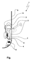
- FIG. 1 shows one schematic representation of a tank flap system according to the invention for a motor vehicle in a rearward Part of a right vehicle corner in plan view
- a vehicle outer wall 9 is connected to a tail light 6 directly after a tank flap system 1 assigned, which includes a fuel filler flap 2, on which a tank flap hinge 3 is attached.
- the tank flap hinge 3 is in the direction of travel with respect to the tank flap system 1 of the motor vehicle arranged forward.
- One Locking mechanism 4 is on the opposite Side of the fuel filler flap hinge 3 is provided.
- a tank filler neck is not for reasons of clarity instead, the tank lid sitting thereon is 8 shown.
- the locking mechanism 4 locks and unlocks the fuel filler flap.
- the locking mechanism 4 is a Bowden cable 7 of an electromotive Actuator 5 actuated.
- the Bowden cable 7 can Steel or a plastic rope include.
- the tank flap system 1 is advantageously as a module with the actuator 5, the Bowden cable 7, the Tank flap hinge 3 and the fuel filler flap 2 preassembled and therefore becomes a complete unit during final assembly used. Connections between the modules tail light 6 and tank flap system 1 do not exist.
- the Modules are each spatially separated according to their function and can also be mounted separately or repaired later become. In dashed line is the fuel filler flap 2 and the tank flap hinge 3 in the unfolded state shown.
- Der Actuator 5 is connected to the central locking of the motor vehicle in a known from the prior art Way coupled.
- the tail light 6 result on one side of the vehicle Simplification and simplification of the body structure, especially during deep drawing of the body panels.
- the sheets can thus be made cheaper become.
- the tank flap system 1 does not move directly to the tail light 6 be because the actuator 5 requires a certain amount of space, or if the actuator still on the housing unit would be mounted, the luggage space would be reduced become what is not wanted.
- the actuator 5 By the relocation of the actuator 5 to the tank flap hinge. 3 If a clearance is created in the area of the rear light 6, which brings benefits for the package and for example can be used as a larger luggage space.
Abstract
Description
Die Erfindung bezieht sich auf ein Tankklappensystem für ein Kraftfahrzeug mit einer Tankklappe, einem an dieser Tankklappe befindlichen Tankklappenscharnier, dem bezüglich der Tankklappe ein Verriegelungsmechanismus gegenüberliegend angeordnet ist, und einem elektromotorischen Stellantrieb zur Betätigung des Verriegelungsmechanismusses.The invention relates to a tank flap system for a motor vehicle with a fuel filler flap, a Tank flap hinge located on this tank flap, with respect to the fuel filler flap a locking mechanism is arranged opposite, and an electromotive Actuator for actuating the locking mechanism.
In der Praxis ist es zunehmend üblich, in ein Tankklappensystem für ein Kraftfahrzeug zumindest einen elektromotorischen Stellantrieb mit einzubeziehen. Der elektromotorische Stellantrieb dient entweder dazu, die Tankklappe zu verschwenken oder die Tankklappe zu verund entriegeln oder beides gleichzeitig. Gewöhnlich ist ein vorhandener Verriegelungsmechanismus der Schwenkachse der Tankklappe hinsichtlich des Einfüllstutzens für den Treibstoff gegenüberliegend angeordnet.In practice, it is increasingly common in one Tank flap system for a motor vehicle at least one include electromotive actuator with. Of the Electromotive actuator is used either to Swing the fuel filler flap or the fuel filler flap to verund unlock or both at the same time. Usually is an existing locking mechanism of the pivot axis the fuel filler flap with respect to the filler neck for the Fuel arranged opposite.
Die EP 0 990 548 A2 offenbart eine Tankklappeneinheit zum Einbau in ein Kraftfahrzeug, die einen Muldenkörper umfasst, an dem eine Tankklappe schwenkbar angebracht ist, auf die ein Stellmotor einwirkt. Der Stellmotor ist senkrecht zur Schwenkachse an deren unteren Ende angeordnet. Nach dem Einbau der Tankklappeneinheit in das Kraftfahrzeug schwenkt der Stellmotor die Tankklappe zum Öffnen und Schließen vom Tankdeckel weg bzw. auf den Tankdeckel zu, und zwar aufgrund einer Betätigung eines Schalters im Fahrzeuginneren. Der Stellmotor bildet einen Teil der vormontierten Tankklappeneinheit.EP 0 990 548 A2 discloses a tank flap unit for installation in a motor vehicle, a dump body comprises, on which a fuel filler flap pivotally mounted is acting on a servomotor. The servomotor is perpendicular to the pivot axis at the lower end arranged. After installing the tank flap unit in the motor vehicle pivots the servomotor the fuel filler flap to open and close the tank lid off or on the Tank lid to, due to an operation of a Switch in the vehicle interior. The servomotor forms one Part of the pre-assembled tank flap unit.
Aus der EP 0 608 527 B1 ist ein Tankverschlusssystem für einen Kraftstoffbehälter eines Kraftfahrzeuges mit einem Einfüllstutzen und einem diesen dichtend verschließenden Tankdeckel bekannt, der mit einer um eine Drehachse schwenkbaren Tankklappe eine Einheit bildet, die mittels eines Antriebsmotors zur Freigabe oder zum Verschließen des Einfüllstutzens zu betätigen ist. In einer Ausführungsform ist die karosseriefeste Drehachse dem Verriegelungsmechanismus, bestehend aus einem Verriegelungsbolzen und einem Fanghaken, bezüglich des Tankdeckels gegenüberliegend angeordnet.From EP 0 608 527 B1 is a tank closure system for a fuel tank of a motor vehicle with a filler neck and a sealing this sealing Tank cap known, with one around a Pivot axis pivotable tank flap forms a unit, by means of a drive motor for release or for Closing the filler neck is to operate. In a Embodiment is the body-fixed axis of rotation Locking mechanism, consisting of a locking bolt and a fishing hook, relative to the fuel cap arranged opposite.
Die DE 101 60 652 A1 zeigt ein Kraftfahrzeug mit einer Tankklappe im Bereich eines hinteren Kotflügels unmittelbar angrenzend zu einer auf dieser Fahrzeugseite befindlichen Rückleuchte. Die Tankklappe wird zum Öffnen in Richtung der Fahrzeugfront geschwenkt. Ein elektrischer Stellmotor ver- und entriegelt über einen Verriegelungsmechanismus die Tankklappe. Der Stellmotor und die auf der Fahrzeugseite der Tankklappe befindliche angrenzende Rückleuchte des Kraftfahrzeuges bilden eine Baueinheit und verkürzen somit den mechanischen Wirkungsweg zwischen Stellmotor und Verriegelungsmechanismus auf ein Minimum. Der Stellmotor und der Verriegelungsmechanismus sind einem Tankklappenscharnier bezüglich der Tankklappe im geschlossenen Zustand gegenüberliegend angeordnet.DE 101 60 652 A1 shows a motor vehicle with a fuel filler flap in the area of a rear mudguard immediately adjacent to one on this side of the vehicle located tail light. The fuel filler flap opens swung in the direction of the vehicle front. An electrical Actuator locks and unlocks via a locking mechanism the fuel filler flap. The servomotor and the adjacent to the vehicle side of the fuel filler flap Rear light of the motor vehicle form a structural unit and thus shorten the mechanical pathway between servomotor and locking mechanism on a Minimum. The servomotor and the locking mechanism are a tank flap hinge with respect to the fuel filler flap arranged opposite each other in the closed state.
Im Weiteren offenbart die DE 101 15 153 A1 eine Vorrichtung zum Ver- und/oder Entriegeln einer Tankklappe, die eine Tankmulde über einen elektromotorischen Stellantrieb verschließt. Der Stellantrieb ist auf einem Montageteil an der Tankmulde in unmittelbarer Nähe zu einem Verriegelungsmechanismus mit Stößel und Anlaufschräge befestigt. Der Stellantrieb befindet sich auf der gegenüberliegenden Seite einer Schwenkachse für die Tankklappe bezüglich der Tankmulde.Furthermore, DE 101 15 153 A1 discloses a Device for locking and / or unlocking a fuel filler flap, the one Tankmulde over a electromotive Actuator closes. The actuator is on one Mounting part at the tank well in close proximity to one Locking mechanism with plunger and run-on slope attached. The actuator is located on the opposite side Side of a pivot axis for the fuel filler flap with regard to the tank recess.
Es ist Aufgabe der Erfindung, ein verbessertes Tankklappensystem der eingangs genannten Art zu schaffen, dass einfacher und kompakter aufgebaut und zudem leicht zu montieren ist.It is an object of the invention to provide an improved Tank flap system of the type mentioned to create that is simpler and more compact and also lightweight to assemble.
Erfindungsgemäß wird die Aufgabe dadurch gelöst, dass der elektromotorische Stellantrieb auf der Seite des Tankklappenscharniers angeordnet ist.According to the invention, this object is achieved that the electromotive actuator on the Side of the fuel filler flap hinge is arranged.
Das Tankklappenscharnier benötigt aufgrund des Scharnierbügels einen entsprechenden Bauraum. Die dadurch entstehenden Hohlräume können zumindest zum Teil für den elektromotorischen Stellantrieb genutzt werden. Somit wird der für den Stellantrieb erforderliche Bauraum zum Tankklappenscharnier verlagert und der verbrauchte Bauraum am Verriegelungsmechanismus entsprechend gesenkt. Der Verriegelungsmechanismus wird über ein mechanisches Verbindungsglied vom Stellantrieb betätigt.The tank flap hinge requires due to the Hinge bracket a corresponding space. The result resulting cavities can be at least partially for the electromotive actuator can be used. Consequently is required for the actuator space for Tank flap hinge shifts and the used space lowered accordingly on the locking mechanism. The locking mechanism is via a mechanical Link operated by the actuator.
Die Vorteile der Erfindung sind, ein geringerer benötigter Bauraum auf der Seite des Verriegelungsmechanismusses und durch die Zusammenlegung, also einer Konzentration, der schwereren mechanischen Elemente, wie Scharnier und Stellantrieb, eine Erleichterung der Montage des Tankklappensystems.The advantages of the invention are a lesser Required space on the side of the locking mechanism and by merging, that is concentration, heavier mechanical elements, such as Hinge and actuator, a facilitation of assembly the tank flap system.
Zweckmäßigerweise ist das Tankklappenscharnier in Bezug auf das Tankklappensystem in Fahrtrichtung des Kraftfahrzeuges nach vorne angeordnet. Eine solche Anordnung senkt das Risiko der Beschädigung der Tankklappe, denn sollte sich das Kraftfahrzeug nach vorne bewegen, bevor die Tankklappe nach einem Öffnen wieder geschlossen wurde, so klappt die Tankklappe bei geringem entgegenstehenden Widerstand ohne Beschädigung wieder zu. Der Widerstand kann beispielsweise bereits der Luftwiderstand bei schneller Autofahrt sein.Conveniently, the tank flap hinge with respect to the tank flap system in the direction of travel of Motor vehicle arranged forward. Such an arrangement reduces the risk of damage to the fuel filler flap, because the motor vehicle should move forward, before the fuel filler flap closes again after opening was, then the fuel filler flap works in low contrasting Resistance without damage again. The resistance for example, the air resistance at be fast car ride.
Da bei Kraftfahrzeugen das Tankklappensystem zunehmend am hinteren Fahrzeugende angeordnet ist, vgl. die oben genannte DE 101 60 652 A1, da sich dadurch Vereinfachungen beim Tiefziehen der Bleche ergeben, sich dort jedoch im Fahrzeuginneren das Rückleuchtegehäuse befindet, ist eine Kombination von Rückleuchtegehäuseplatte und Stellmotor, wie in der letztgenannten Patentanmeldung vorgeschlagen, nicht mehr erforderlich, da erfindungsgemäß, im Gegensatz zum oben genannten Stand der Technik, der elektromotorische Stellantrieb in Fahrzeugfahrtrichtung weiter nach vorne verlegt ist. Die Baugruppen Rückleuchte und Tankklappensystem sind deshalb (wieder) funktional getrennt. Ein weiterer Vorteil ist die unkompliziertere Baugruppenanordnung (Package) am hintersten Kotflügelteil im Grenzbereich zur Rückleuchte. Durch diese Anordnung kann auch der Gepäckraum des Kraftfahrzeuges vergrößert werden.As in motor vehicles, the tank flap system is increasingly located at the rear end of the vehicle, cf. the above-mentioned DE 101 60 652 A1, since this simplifies during deep drawing of the sheets, arise However, there is the rear light housing inside the vehicle, is a combination of rear light housing plate and servomotor, as in the latter patent application proposed, no longer necessary since according to the invention, in contrast to the above-mentioned prior art, the electromotive actuator in vehicle travel direction moved further forward. The assemblies tail light and tank flap system are therefore (again) functional separated. Another advantage is the less complicated Assembly arrangement (package) on the rearmost fender part in the border area to the tail light. Through this Arrangement can also be the luggage compartment of the motor vehicle be enlarged.
Bevorzugt umfasst die Verbindung zwischen dem elektromotorischen Stellantrieb und dem Verriegelungsmechanismus ein mechanisches Verbindungsglied, insbesondere einen Bowdenzug (Seilzug). Dieses ist aufgrund der räumlichen Trennung von elektrischem Stellantrieb und Verriegelungsmechanismus nötig, um die mechanische Ver- und Entriegelungsbewegung vom Stellantrieb zum Verriegelungsmechanismus zu übertragen. Ein Bowdenzug ist preiswert und arbeitet zuverlässig. Außerdem lässt er auch leichte Radien zum Richtungswechsel zu, da im Regelfall die Ansteuerung des Verriegelungsmechanismusses aus einer anderen Richtung erfolgt, als der elektrische Stellantrieb bereitstellt, weil der elektrische Stellantrieb bauraumoptimiert angeordnet ist.Preferably, the connection between the electromotive actuator and the locking mechanism a mechanical link, in particular a Bowden cable (cable). This is due to the spatial Separation of electric actuator and locking mechanism necessary to the mechanical and Unlocking movement from the actuator to the locking mechanism transferred to. A Bowden cable is cheap and works reliably. He also leaves it easy Radii to change direction, as usually the control of the locking mechanism from another Direction takes place as the electric actuator provides, because the electric actuator space-optimized is arranged.
Bei einer alternativen Ausführungsform umfasst die Verbindung zwischen dem elektromotorischen Stellantrieb und dem Verriegelungsmechanismus eine Gliederkette. Dadurch sind Richtungswechsel mit einem größeren Winkel auf kleinerem Raum im Vergleich zu einem Bowdenzug möglich. Denkbar ist auch eine Kombination aus Gliederkette und Seilzug. Damit werden die Vorteile dieser mechanischen Elemente verbunden.In an alternative embodiment the connection between the electromotive actuator and the locking mechanism is a link chain. This changes direction with a larger angle in a smaller space compared to a Bowden cable possible. Also conceivable is a combination of link chain and cable. This will be the advantages of this mechanical Connected elements.
In weiterer Ausgestaltung bildet der elektromotorische Stellantrieb mit dem Tankklappenscharnier ein in sich geschlossenes, vormontierbares Modul. Dadurch erleichtert sich die Montage beim Einbau des Tankklappensystems und der Bauraum wird noch besser optimiert.In a further embodiment of the electromotive forms Actuator with the tank flap hinge on self-contained, pre-assembled module. Thereby Assembly is easier when installing the tank flap system and the space is even better optimized.
Vorteilhaft ist es, wenn das Tankklappensystem als montagegerechtes Modul ausgebildet ist. Dann kann das ganze Tankklappensystem-Modul in einem Montagearbeitsschritt im Kraftfahrzeug montiert werden.It is advantageous if the tank flap system is designed as a module suitable for assembly. Then that can entire tank flap system module in an assembly step be mounted in the vehicle.
Es versteht sich, dass die vorstehend genannten und nachstehend noch zu erläuternden Merkmale nicht nur in der jeweils angegebenen Kombination, sondern auch in anderen Kombinationen verwendbar sind. Der Rahmen der vorliegenden Erfindung ist nur durch die Ansprüche definiert. It is understood that the above and features to be explained below not only in the specified combination, but also in other combinations are usable. The frame of the The present invention is defined only by the claims.
Die Erfindung wird im Folgenden anhand eines Ausführungsbeispieles unter Bezugnahme auf die zugehörige Zeichnung näher erläutert. Die einzige Figur zeigt eine schematische Darstellung eines erfindungsgemäßen Tankklappensystems für ein Kraftfahrzeug in einem rückwärtigen Teil einer rechten Fahrzeugecke in der DraufsichtThe invention will be described below with reference to a Embodiment with reference to the associated Drawing explained in more detail. The only figure shows one schematic representation of a tank flap system according to the invention for a motor vehicle in a rearward Part of a right vehicle corner in plan view
Einer Fahrzeugaußenwand 9 ist an eine Rückleuchte
6 direkt anschließend ein Tankklappensystem 1 zugeordnet,
das eine Tankklappe 2 umfasst, an der ein Tankklappenscharnier
3 befestigt ist. Das Tankklappenscharnier
3 ist in Bezug auf das Tankklappensystem 1 in Fahrtrichtung
des Kraftfahrzeuges nach vorne angeordnet. Ein
Verriegelungsmechanismus 4 ist auf der gegenüberliegenden
Seite des Tankklappenscharniers 3 vorgesehen. Ein Tankeinfüllstutzen
ist aus Übersichtlichkeitsgründen nicht
gezeigt, stattdessen ist der darauf sitzende Tankdeckel 8
dargestellt. Der Verriegelungsmechanismus 4 verriegelt
und entriegelt die Tankklappe. Der Verriegelungsmechanismus
4 wird über einen Bowdenzug 7 von einem elektromotorischen
Stellantrieb 5 betätigt. Der Bowdenzug 7 kann ein
Stahl- oder ein Kunststoffseil umfassen.A vehicle outer wall 9 is connected to a
Das Tankklappensystem 1 ist vorteilhafterweise
als Modul mit dem Stellantrieb 5, dem Bowdenzug 7, dem
Tankklappenscharnier 3 und der Tankklappe 2 vormontiert
und wird demzufolge bei der Endmontage als ganze Einheit
eingesetzt. Verbindungen zwischen den Baugruppen Rückleuchte
6 und Tankklappensystem 1 bestehen nicht. Die
Baugruppen sind jeweils nach ihrer Funktion räumlich getrennt
und können auch getrennt montiert bzw. später repariert
werden. In gestrichelter Linie ist die Tankklappe
2 und das Tankklappenscharnier 3 im ausgeklappten Zustand
gezeigt.The
Wenn die Tankklappe 2 entriegelt ist, besteht
ein Zugang zum schematisch angedeuteten Tankdeckel 8. Der
Stellantrieb 5 ist mit der Zentralverriegelung des Kraftfahrzeuges
in einer aus dem Stand der Technik bekannten
Weise gekoppelt.If the
Aufgrund der Anordnung des Tankklappensystems 1
am hinteren Ende eines hinteren Kotflügels angrenzend zu
der Rückleuchte 6 auf der einen Fahrzeugseite ergeben
sich Vereinfachungen und Erleichterungen beim Karosserieaufbau,
insbesondere beim Tiefziehen der Karosseriebleche.
Die Bleche können somit kostengünstiger gefertigt
werden. Bei einem Aufbau eines Tankklappensystems 1 mit
einem Stellantrieb 5 auf der Gehäuseeinheit der Rückleuchte
6 gemäß dem Stand der Technik kann das Tankklappensystem
1 nicht direkt an die Rückleuchte 6 verlagert
werden, da der Stellantrieb 5 einen gewissen Bauraum erfordert,
oder wenn der Stellantrieb trotzdem auf der Gehäuseeinheit
montiert würde, würde der Gepäckraum verkleinert
werden, was nicht erwünscht ist. Durch die Verlagerung
des Stellantriebs 5 zum Tankklappenscharnier 3
wird ein Freiraum im Bereich der Rückleuchte 6 geschaffen,
der Vorteile für das Package bringt und beispielsweise
als größerer Gepäckraum genutzt werden kann. Due to the arrangement of the
- 1.1.
- TankklappensystemTank flap system
- 2.Second
- Tankklappetank flap
- 3.Third
- TankklappenscharnierFuel filler door hinge
- 4.4th
- Verriegelungsmechanismuslocking mechanism
- 5.5th
- Elektromotorischer StellantriebElectromotive actuator
- 6.6th
- RückleuchteTaillight
- 7.7th
- BowdenzugBowden
- 8.8th.
- Tankdeckelfiller cap
- 9.9th
- FahrzeugaußenhautVehicle shell
Claims (6)
Applications Claiming Priority (2)
| Application Number | Priority Date | Filing Date | Title |
|---|---|---|---|
| DE200410002818 DE102004002818A1 (en) | 2004-01-20 | 2004-01-20 | Tank flap system for a motor vehicle |
| DE102004002818 | 2004-01-20 |
Publications (2)
| Publication Number | Publication Date |
|---|---|
| EP1557313A2 true EP1557313A2 (en) | 2005-07-27 |
| EP1557313A3 EP1557313A3 (en) | 2006-03-15 |
Family
ID=34625720
Family Applications (1)
| Application Number | Title | Priority Date | Filing Date |
|---|---|---|---|
| EP05000770A Withdrawn EP1557313A3 (en) | 2004-01-20 | 2005-01-15 | Fuel door system for a motor vehicle |
Country Status (2)
| Country | Link |
|---|---|
| EP (1) | EP1557313A3 (en) |
| DE (1) | DE102004002818A1 (en) |
Cited By (1)
| Publication number | Priority date | Publication date | Assignee | Title |
|---|---|---|---|---|
| EP1935702A1 (en) * | 2006-12-20 | 2008-06-25 | GM Global Technology Operations, Inc. | Fuel flap module |
Families Citing this family (2)
| Publication number | Priority date | Publication date | Assignee | Title |
|---|---|---|---|---|
| DE102005051140A1 (en) * | 2005-10-26 | 2007-05-03 | GM Global Technology Operations, Inc., Detroit | Tank flap module with integrated locking device |
| DE102006042447A1 (en) * | 2006-05-06 | 2007-11-08 | Bayerische Motoren Werke Ag | Motor vehicle with pivotably mounted tank flap has movable from closed to open position by drive unit, whereby spring element is tensioned by which tank flap can be pivoted from open position back into closed position |
Citations (4)
| Publication number | Priority date | Publication date | Assignee | Title |
|---|---|---|---|---|
| EP0608527A1 (en) | 1992-12-15 | 1994-08-03 | WEBASTO KAROSSERIESYSTEME GmbH | Fuel tank closure for a vehicle |
| EP0990548A2 (en) | 1998-09-30 | 2000-04-05 | Volkswagen Aktiengesellschaft | Tank inlet cover assembly |
| DE10115153A1 (en) | 2001-03-27 | 2002-10-17 | Hella Kg Hueck & Co | Device for locking and / or unlocking a tank flap, which closes a tank recess |
| DE10160652A1 (en) | 2001-12-11 | 2003-07-10 | Opel Adam Ag | Motor vehicle with tank flap and rear light has tank flap locking and unlocking actuator motor and rear light on vehicle side of tank flap formed into a unit |
Family Cites Families (2)
| Publication number | Priority date | Publication date | Assignee | Title |
|---|---|---|---|---|
| US5769481A (en) * | 1996-07-26 | 1998-06-23 | Ford Global Technologies, Inc. | Interlock mechanism for vehicle sliding door and fuel filler door |
| DE50214532D1 (en) * | 2002-05-15 | 2010-08-26 | Ford Global Tech Llc | Fuel filler door unit |
-
2004
- 2004-01-20 DE DE200410002818 patent/DE102004002818A1/en not_active Ceased
-
2005
- 2005-01-15 EP EP05000770A patent/EP1557313A3/en not_active Withdrawn
Patent Citations (4)
| Publication number | Priority date | Publication date | Assignee | Title |
|---|---|---|---|---|
| EP0608527A1 (en) | 1992-12-15 | 1994-08-03 | WEBASTO KAROSSERIESYSTEME GmbH | Fuel tank closure for a vehicle |
| EP0990548A2 (en) | 1998-09-30 | 2000-04-05 | Volkswagen Aktiengesellschaft | Tank inlet cover assembly |
| DE10115153A1 (en) | 2001-03-27 | 2002-10-17 | Hella Kg Hueck & Co | Device for locking and / or unlocking a tank flap, which closes a tank recess |
| DE10160652A1 (en) | 2001-12-11 | 2003-07-10 | Opel Adam Ag | Motor vehicle with tank flap and rear light has tank flap locking and unlocking actuator motor and rear light on vehicle side of tank flap formed into a unit |
Cited By (2)
| Publication number | Priority date | Publication date | Assignee | Title |
|---|---|---|---|---|
| EP1935702A1 (en) * | 2006-12-20 | 2008-06-25 | GM Global Technology Operations, Inc. | Fuel flap module |
| US7914063B2 (en) | 2006-12-20 | 2011-03-29 | GM Global Technology Operations LLC | Fuel tank cover module |
Also Published As
| Publication number | Publication date |
|---|---|
| EP1557313A3 (en) | 2006-03-15 |
| DE102004002818A1 (en) | 2005-08-11 |
Similar Documents
| Publication | Publication Date | Title |
|---|---|---|
| DE10026327B4 (en) | Power actuator for a vehicle door | |
| EP0826539B1 (en) | Movable roof construction for convertible passenger vehicle | |
| DE102004010294B4 (en) | Tank recess for automobiles | |
| DE102019105830B4 (en) | DOUBLE-PULL LOCKING ARRANGEMENTS FOR MOTOR VEHICLE COMPARTMENT LOCKING ARRANGEMENTS | |
| DE102008003994A1 (en) | Pivoting device for a vehicle door | |
| WO2006053547A2 (en) | Hatch for a motor vehicle | |
| EP2129539B1 (en) | Circuit of the electric actuation of the two-part tailgate for motor vehicles | |
| EP1557313A2 (en) | Fuel door system for a motor vehicle | |
| DE102018126515B4 (en) | Locking mechanism for an interior locking assembly of a motor vehicle | |
| DE102006043817A1 (en) | Movement mechanism for storage compartment flap for closing opening in vehicle wall of omnibus, has lifting kinematics, and storage compartment flap is automatically transferred between closing and opening position by drive device | |
| DE102008064374B3 (en) | Opening and closing device of a top compartment lid | |
| DE102005018859A1 (en) | Sliding door and vehicle with sliding door | |
| EP1812671B1 (en) | Combined closing device | |
| DE19848633B4 (en) | Motor vehicle door with self-supporting interior trim | |
| EP1710107A2 (en) | Vehicle side door arrangement | |
| WO2011095432A1 (en) | Device for closing a pivoting flap and flap and motor vehicle having said device | |
| EP1404568B1 (en) | Pivotable cover lid for a convertible | |
| DE102020133915A1 (en) | motor vehicle lock | |
| DE202005018026U1 (en) | Tail unit for motor vehicle has tailgate pivoting drive and at least one further functional component combined with unit support to form module for mounting in vehicle body rear end region | |
| DE102010027751B4 (en) | motor vehicle | |
| DE102006062252A1 (en) | Motor vehicle has hinge device for rotary actuating front hood, which covers front side vehicle opening, and hinge device is arranged to partly cover outside of vehicle opening and adjacent body part | |
| WO2019063040A1 (en) | Motor vehicle lock | |
| DE10031850A1 (en) | Vehicle door assembly | |
| DE102017106606A1 (en) | Actuator for a motor vehicle flap element | |
| DE102012013779A1 (en) | Method for closing or opening a door, tailgate or the like on the bodywork of a motor vehicle |
Legal Events
| Date | Code | Title | Description |
|---|---|---|---|
| PUAI | Public reference made under article 153(3) epc to a published international application that has entered the european phase |
Free format text: ORIGINAL CODE: 0009012 |
|
| AK | Designated contracting states |
Kind code of ref document: A2 Designated state(s): AT BE BG CH CY CZ DE DK EE ES FI FR GB GR HU IE IS IT LI LT LU MC NL PL PT RO SE SI SK TR |
|
| AX | Request for extension of the european patent |
Extension state: AL BA HR LV MK YU |
|
| RAP1 | Party data changed (applicant data changed or rights of an application transferred) |
Owner name: GM GLOBAL TECHNOLOGY OPERATIONS, INC. |
|
| PUAL | Search report despatched |
Free format text: ORIGINAL CODE: 0009013 |
|
| AK | Designated contracting states |
Kind code of ref document: A3 Designated state(s): AT BE BG CH CY CZ DE DK EE ES FI FR GB GR HU IE IS IT LI LT LU MC NL PL PT RO SE SI SK TR |
|
| AX | Request for extension of the european patent |
Extension state: AL BA HR LV MK YU |
|
| AKX | Designation fees paid | ||
| STAA | Information on the status of an ep patent application or granted ep patent |
Free format text: STATUS: THE APPLICATION IS DEEMED TO BE WITHDRAWN |
|
| 18D | Application deemed to be withdrawn |
Effective date: 20060916 |
|
| REG | Reference to a national code |
Ref country code: DE Ref legal event code: 8566 |