EP1557308B1 - Dispositif pour le refroidissement d'air d'un espace de véhicule et un véhicule avec un tel dispositif - Google Patents
Dispositif pour le refroidissement d'air d'un espace de véhicule et un véhicule avec un tel dispositif Download PDFInfo
- Publication number
- EP1557308B1 EP1557308B1 EP05100305A EP05100305A EP1557308B1 EP 1557308 B1 EP1557308 B1 EP 1557308B1 EP 05100305 A EP05100305 A EP 05100305A EP 05100305 A EP05100305 A EP 05100305A EP 1557308 B1 EP1557308 B1 EP 1557308B1
- Authority
- EP
- European Patent Office
- Prior art keywords
- condenser
- air
- housing
- longitudinal axis
- vehicle
- Prior art date
- Legal status (The legal status is an assumption and is not a legal conclusion. Google has not performed a legal analysis and makes no representation as to the accuracy of the status listed.)
- Expired - Lifetime
Links
Images


Classifications
-
- B—PERFORMING OPERATIONS; TRANSPORTING
- B60—VEHICLES IN GENERAL
- B60H—ARRANGEMENTS OF HEATING, COOLING, VENTILATING OR OTHER AIR-TREATING DEVICES SPECIALLY ADAPTED FOR PASSENGER OR GOODS SPACES OF VEHICLES
- B60H1/00—Heating, cooling or ventilating devices
- B60H1/00357—Air-conditioning arrangements specially adapted for particular vehicles
- B60H1/00378—Air-conditioning arrangements specially adapted for particular vehicles for tractor or load vehicle cabins
-
- B—PERFORMING OPERATIONS; TRANSPORTING
- B60—VEHICLES IN GENERAL
- B60H—ARRANGEMENTS OF HEATING, COOLING, VENTILATING OR OTHER AIR-TREATING DEVICES SPECIALLY ADAPTED FOR PASSENGER OR GOODS SPACES OF VEHICLES
- B60H1/00—Heating, cooling or ventilating devices
- B60H1/00321—Heat exchangers for air-conditioning devices
- B60H1/00328—Heat exchangers for air-conditioning devices of the liquid-air type
-
- B—PERFORMING OPERATIONS; TRANSPORTING
- B60—VEHICLES IN GENERAL
- B60H—ARRANGEMENTS OF HEATING, COOLING, VENTILATING OR OTHER AIR-TREATING DEVICES SPECIALLY ADAPTED FOR PASSENGER OR GOODS SPACES OF VEHICLES
- B60H1/00—Heating, cooling or ventilating devices
- B60H1/32—Cooling devices
- B60H1/3204—Cooling devices using compression
- B60H1/3227—Cooling devices using compression characterised by the arrangement or the type of heat exchanger, e.g. condenser, evaporator
Definitions
- the invention relates to a device for cooling air for a vehicle associated with a room, in particular a cabin of an agricultural or industrial utility vehicle.
- the device comprises a compressor and / or an evaporator, a condenser, an air guiding device and connecting lines.
- the condenser can be connected to the compressor or the evaporator by means of the connection lines. With the louver air for cooling the condenser the capacitor can be fed.
- Such devices have long been known from the prior art - for example, as air conditioners - and are used in passenger cars but also in trucks and agricultural vehicles.
- the heat transfer is usually accomplished by means of a refrigerant, which changes its state of aggregation, for example, from liquid to vapor and vice versa, and thereby absorbs or releases heat.
- a refrigerant which changes its state of aggregation, for example, from liquid to vapor and vice versa, and thereby absorbs or releases heat.
- the evaporator which is usually arranged in a vehicle cabin, the refrigerant changes from the liquid to the gaseous state and absorbs heat which it extracts from the immediate environment, that is to say the vehicle cabin.
- the evaporated refrigerant is compressed or compressed, so that it can go back into the liquid state of matter in the condenser - condense - can, whereby heat is generated.
- This heat is usually released by the condenser into the air of the environment.
- the air conditioning system can also be operated with R152a or CO2 as the cooling medium, which in itself is also known from the prior art.
- CO2 is used as the cooling medium
- the condenser is referred to as a gas cooler.
- the condenser is usually arranged in the region of the vehicle radiator, where air is exhausted by means of a fan the environment is drawn on the one hand by the condenser and on the other hand by the vehicle radiator, wherein the heat generated in the condenser can be discharged into the air.
- An apparatus for cooling air for a vehicle associated with a space according to the features of the preamble of claim 1, for example, from EP 1 342 598 A1 known.
- the present invention is therefore an object of the invention to provide a device and a vehicle of the type mentioned and further, by which the aforementioned problems are overcome.
- a device of the type mentioned is characterized in that the capacitor is arranged in spatial proximity to the room.
- the capacitor is, so to speak, no longer under the hood, but instead near the space associated with the vehicle, in other words, for example, near the vehicle cabin.
- the condenser has, at least in sections, an essentially prism-shaped, cuboidal or cylindrical shape, wherein a tubular shape is conceivable.
- the condenser is formed as a hollow cylinder, in which case not only the outer region of the hollow cylinder, but also the inner region of the hollow cylinder can be flowed around or flowed through by air, so that cooling can take place as a result.
- the capacitor is arranged substantially vertically. Especially in this case, an elongated shape of the hollow cylinder could be provided, so that the capacitor is similar to the appearance of an exhaust pipe in a near-cabin assembly.
- the capacitor could also be arranged at an angle to the vertical of less than 45 degrees with respect to its longitudinal axis. It is also conceivable that a plurality of cuboid-shaped capacitors - for example three - are connected to each other and / or are each arranged slightly tilted, i. at an angle to the vertical.
- the capacitor has, at least in sections, essentially a hollow cylindrical shape with a plurality of channels running in the radial direction.
- the channels connect the interior of the hollow cylindrical condenser to the exterior of the hollow cylindrical condenser.
- the air provided for cooling the condenser can be supplied by the air guiding device to the outer or the inner region of the condenser. At least part of the air supplied to the outer and inner regions, respectively through the channels into the inner and the outer region of the hollow cylinder can be conveyed and deducted. To that extent, a configuration comparable to a ring cooler or a ring capacitor configuration can be realized by this configuration of the capacitor, which advantageously has a high efficiency.
- the capacitor has a substantially elongate shape.
- the condenser configured in this way could be surrounded by air in its longitudinal direction, so that heat is exchanged as a result.
- the capacitor could further comprise channels which extend in the direction of the longitudinal axis or a transverse axis of the capacitor and through which air can be conducted. Thus, heat exchange is also due to the air flow through the channels.
- the capacitor could have a curved shape in its longitudinal direction, namely in particular if it is to be adapted to the shape of a component at its place of installation.
- the capacitor could be arranged in an at least partially substantially cylindrical, cuboid or prism-shaped housing.
- the housing preferably forms part of the air guiding device, so that the effectiveness of the air flow or air flow through the condenser can be further increased by the housing or the air guiding device.
- the housing has a housing longitudinal axis.
- a capacitor also has a capacitor longitudinal axis. At least one capacitor is arranged in the housing such that the two longitudinal axes enclose an angle which is less than 90 degrees.
- the capacitor or a plurality of capacitors are arranged with respect to the housing slightly tilted to the vertical. A flow through such Condenser with air could in this case take place in a direction transverse to its longitudinal axis.
- the condenser could be traversed by air substantially in the horizontal direction or transversely to its longitudinal axis.
- at least one fan device could be provided, with which air can be conducted through a part of the condenser.
- Such a fan device could be designed in the form of a blower and be directly upstream or downstream of the condenser, in order to blow or suck air through the condenser.
- a fan device which sucks air and transported by means of the louver to the condenser.
- the fan device could be formed in the simplest case in the form of a fan or a fan.
- the aspirated air is preferably air coming from the surroundings.
- the mounting location of the fan device could be provided upstream and / or at the upper end of the substantially vertical capacitor. Accordingly, the fan device could suck in ambient air and, as a result of the overpressure generated thereby, push the air past the condenser or push it through.
- a fan device "pulling” or “pushing” can be used, and accordingly transport air due to negative pressure or pressure.
- a fan device could also be arranged and operated in such a way that due to a negative pressure generated by the fan device, the air is drawn past the condenser.
- the housing could have for cleaning and / or maintenance purposes, for example, in the form of a flap opening through which on the Components in the housing can be accessed.
- the housing is at least partially formed two or more parts and is designed to be accessible and openable for easy access.
- the housing may be formed such that a housing part is removable, swiveling or hinged to the other housing part fastened.
- a division into two is preferably provided along the housing longitudinal direction.
- At least one fan device could be fastened to one housing part and at least one capacitor to another housing part.
- two ventilation devices could be provided, which are arranged in the direction of air flow before and after the condenser. Now, if the one housing part is opened or opened, on which the ventilation devices are mounted, the ventilation devices fold up together with this housing part and move away from the condenser together with the housing part. The arranged on the other housing part condenser remains stationary on the other housing part, so that both the ventilation devices and the capacitor are separately and easily accessible.
- a capacitor is arranged downstream in a preferred embodiment in the air flow direction of a fan device.
- a plurality of fan devices and a plurality of capacitors are provided, which are arranged alternately one behind the other.
- the condenser together with the possibly provided housing, could be arranged on a front and / or side mounting location viewed in the direction of travel of the vehicle. Preferably, it is in close proximity to an A-post arranged in the form of a cabin space. In such an arrangement of the capacitor, the deterioration of the visibility of the operator located in the cabin can be kept low. This may be the case, in particular, when the condenser is arranged protruding outward from a hood, in particular in the case of an essentially vertical arrangement of the condenser, together with any capacitor housing provided, if appropriate.
- the air drawn in from the environment may be contaminated, for example, by dust or floating in the air small straw or harvested parts. Accordingly, a condenser flowed around by this air would most likely be added after a short period of operation, so that its function is called into question. Therefore, a filter device is provided with which any contaminated ambient air is at least partially cleanable.
- the filter device could, for example, comprise turbulator tubes which operate on the cyclone principle.
- a vehicle is characterized by a device for cooling air for a vehicle-associated space according to one of claims 1 to 12.
- the vehicle is an agricultural or industrial utility vehicle, in particular a tractor.
- the device for cooling air is referenced to avoid repetition of the preceding part of the description.
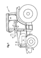
- FIG. 1 schematically shows an executed in the form of a tractor 10 agricultural utility vehicle, which is equipped with the device according to the invention for cooling air.
- the tractor is driven by the internal combustion engine 12, which is cooled by a high-temperature cooling circuit 13, which is shown only schematically, and which has a cooler 14.
- the device for cooling air comprises an evaporator 16 which is arranged in the vehicle cabin 18 of the tractor 10 is.
- the coolant circulating in the device evaporates in the evaporator 16 and draws heat from the vehicle cabin 18 in this case.
- the refrigerant is compressed by the compressor 20 and condenses in the condenser 22. The resulting heat may be released to the ambient air.
- the coolant is passed in its circuit in the schematically illustrated connecting lines 23.
- FIG. 2 shows only schematically a hollow cylindrical capacitor 22, which is arranged in a substantially cylindrically shaped housing 24.
- the in FIG. 2 shown capacitor 22 includes a plurality - not shown - extending in the radial direction channels, which connect the inner region 26 with the outer region 28 of the capacitor 22.
- the housing 24 forms part of the air guiding device, with which air of the environment is supplied to the condenser 22.
- the fan device 30 draws in air from the environment, which is indicated schematically by the arrow 32, and passes the sucked air into the outer region 28 of the condenser 22, that is in the space between the housing 24 and the condenser 22.
- the located in the outer region 28 Air passes through the in FIG. 2 not shown radially extending channels in the inner region 26 of the capacitor 22 and is discharged from this area, which is indicated schematically by the arrows with the reference numeral 34.
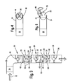
- FIG. 3 shows in a sectional side view in a schematic representation of the FIG. 2 alternative embodiment of a housing 24 in which two capacitors 22 and a three fans 36 having vent means 30 are arranged. In this case, air is sucked in from the environment according to the arrow direction 32 with the aid of the fans 36 and at least roughly cleaned by a filter 38.
- capacitors 22 also have a hollow cylindrical shape and are connected with respect to the flow of coolant in series or in series.
- the mode of operation is as follows: the air pre-cleaned by the filter 38 and sucked in by the first fan arranged in the direction of flow is conducted into the outer region 28 of the first hollow-cylindrical condenser 22.
- This first outer region 28 is bounded downstream by the annular aperture 40, so that the pressurized air is passed through the radially extending channels 50 of the condenser 22 into the inner region 26 of the condenser 22.
- the air, supported by the second fan 36 arranged in the direction of flow is conducted into the outer region 28 of the further condenser 22 arranged in the direction of flow.
- This outer region 28 is also delimited by a second annular diaphragm 40 arranged in the direction of flow, so that the air under pressure there is also conducted through the radial channels 50 of the condenser 22 into the inner region of the condenser 28.
- the interior 26 of the two in FIG. 3 shown capacitors 22 is sealed in each case with a cover plate 42, so that the coming from above, pressurized air does not get directly into the inner region 26 of the capacitors 22, but only via the detour over the outer region 28 and extending in the radial direction channels 50 of the capacitor 22nd
- capacitors 22 and one or two working in the axial direction of capacitors could be provided, which are substantially cylindrical, cuboid or prismatic and through which the air is directed in the direction of the cylinder axis becomes.
- FIG. 4 shows in a plan view in a schematic representation of the housing 24, in which the filter 38, the fan 36 and the capacitors 22 are arranged.
- a hinge 44 is provided on the opposite side of the substantially cylindrically arranged housing portion 24 closing means 46 are provided, with which the housing 24 can be opened or closed.
- FIG. 4 the housing 24 is shown in a closed state.
- FIG. 5 the housing 24 is off FIG. 4 in the same view shown in an open state, wherein the housing part 48 is folded down with respect to the hinge 44, so that both the fans 36 and the capacitors 22 are accessible for maintenance / cleaning purposes in a simple manner.
- FIG. 5 is also shown that the fans 36 are attached to the hinged housing part 48 and the capacitors 22 to the stationary housing part 24.
- FIG. 6 shows an alternative arrangement of the capacitor 22 in the housing 24.
- the capacitor 22 arranged in the housing 24 has a longitudinal axis 54.
- the housing 24 also has an arrow 32 parallel to - not shown - longitudinal axis.
- the capacitor 22 is arranged in the housing 24 such that its longitudinal axis 54 has an angle to the longitudinal axis of the housing 24.
- the introduced from above into the housing 24 air is transverse to the longitudinal axis 54 of the capacitor 22 - indicated by the arrows - passed through the condenser 22, which has corresponding channels 52 for this purpose.
- There is another fan 36 downstream of the condenser 22 which assists a continuous flow of air through the condenser 22.
Landscapes
- Physics & Mathematics (AREA)
- Thermal Sciences (AREA)
- Engineering & Computer Science (AREA)
- Mechanical Engineering (AREA)
- Air-Conditioning For Vehicles (AREA)
- Cooling, Air Intake And Gas Exhaust, And Fuel Tank Arrangements In Propulsion Units (AREA)
Claims (15)
- Dispositif pour le refroidissement de l'air d'un espace associé à un véhicule, notamment d'une cabine d'un véhicule utilitaire agricole ou industriel, comprenant un compresseur (20) et/ou un évaporateur (16), un condenseur (22), un dispositif de guidage d'air (24) et des conduites de connexion (23), le condenseur (22) pouvant être connecté au compresseur (20) ou à l'évaporateur (16) à l'aide des conduites de connexion (23), de l'air pour refroidir le condenseur (22) pouvant être acheminé au condenseur (22) par le biais du dispositif de guidage d'air (24), le condenseur (22) étant disposé à proximité spatiale de l'espace (18), le condenseur (22) présentant au moins en partie une forme essentiellement prismatique, parallélépipédique ou cylindrique, et le condenseur (22) étant disposé essentiellement verticalement ou par rapport à son axe longitudinal suivant un angle inférieur à 45 degrés par rapport à la verticale, caractérisé en ce que le condenseur (22) présente au moins en partie essentiellement une forme cylindrique creuse avec plusieurs canaux (50, 52) s'étendant dans la direction radiale, les canaux (50, 52) reliant une région interne (26) du condenseur cylindrique creux (22) à une région externe (28) du condenseur cylindrique creux (22), l'air prévu pour refroidir le condenseur (22) pouvant être acheminé du dispositif de guidage d'air (24) à la région externe (28) ou à la région interne (26) du condenseur (22), et au moins une partie de l'air acheminé à la région externe (28) ou à la région interne (26) pouvant être transportée par les canaux (50, 52) dans la région interne (26) ou la région externe (28) du cylindre creux et pouvant en être évacuée.
- Dispositif selon la revendication 1, caractérisé en ce que le condenseur (22) présente essentiellement une forme allongée, le condenseur (22) présentant des canaux (50, 52) qui s'étendent dans la direction de l'axe longitudinal ou d'un axe transversal du condenseur (22), de l'air pouvant être guidé à travers les canaux (50, 52).
- Dispositif selon la revendication 2, caractérisé en ce que le condenseur (22) présente une forme courbe dans la direction de son axe longitudinal.
- Dispositif selon l'une quelconque des revendications 1 à 3, caractérisé en ce que le condenseur (22) est disposé dans un boîtier (24) réalisé au moins en partie sous forme essentiellement cylindrique, parallélépipédique ou prismatique, qui forme de préférence une partie du dispositif de guidage d'air (24).
- Dispositif selon la revendication 4, caractérisé en ce que le boîtier (24) présente un axe longitudinal de boîtier, le condenseur (22) étant disposé dans le boîtier (24) de telle sorte que l'axe longitudinal de boîtier et l'axe longitudinale du condenseur (22) forment un angle qui est inférieur à 90 degrés.
- Dispositif selon la revendication 4 ou 5, caractérisé en ce que le condenseur (22) peut être parcouru par l'air essentiellement dans la direction horizontale ou transversalement à son axe longitudinal.
- Dispositif selon l'une quelconque des revendications 1 à 6, caractérisé en ce qu'un dispositif de ventilateur (30, 36) est prévu, lequel aspire de préférence l'air provenant de l'environnement et le transporte au moyen du dispositif de guidage d'air (24) jusqu'au condenseur (22).
- Dispositif selon la revendication 7, caractérisé en ce que le dispositif de ventilateur (30, 36) est disposé en amont et/ou à une extrémité supérieure du condenseur (22) disposé essentiellement verticalement.
- Dispositif selon l'une quelconque des revendications 4 à 8, caractérisé en ce que le boîtier (24) est divisé au moins en partie en deux ou plusieurs parties, pour des besoins de nettoyage et/ou d'entretien, et est réalisé de manière à pouvoir être ouvert et fermé.
- Dispositif selon la revendication 9, caractérisé en ce que la séparation en deux est prévue le long de l'axe longitudinal du boîtier.
- Dispositif selon la revendication 9 ou 10, caractérisé en ce qu'au moins un dispositif de ventilateur (30, 36) est fixé sur une partie du boîtier (48) et au moins un condenseur (22) est fixé sur une autre partie du boîtier.
- Dispositif selon l'une quelconque des revendications 9 à 11, caractérisé en ce que l'au moins un dispositif de ventilateur (36) est monté en aval d'un condenseur (22).
- Dispositif selon l'une quelconque des revendications 9 à 12, caractérisé en ce que plusieurs dispositifs de ventilateur (36) et plusieurs condenseurs (22) sont prévus, lesquels sont disposés en alternance les uns derrière les autres.
- Dispositif selon l'une quelconque des revendications 1 à 13, caractérisé en ce que le dispositif de ventilateur peut être entraîné de manière électrique, et/ou en ce qu'un dispositif de filtre (38) est prévu, avec lequel l'air ambiant non purifié peut être purifié au moins en partie, le dispositif de filtre (38) présentant de préférence des petits tubes générateurs de turbulences.
- Véhicule, en particulier véhicule utilitaire agricole ou industriel, caractérisé par un dispositif pour refroidir de l'air pour un espace (18) associé au véhicule (10) selon l'une quelconque des revendications 1 à 14.
Applications Claiming Priority (2)
| Application Number | Priority Date | Filing Date | Title |
|---|---|---|---|
| DE102004003237A DE102004003237A1 (de) | 2004-01-21 | 2004-01-21 | Vorrichtung zum Kühlen von Luft für einen einem Fahrzeug zugeordneten Raum und Fahrzeug mit einer solchen Vorrichtung |
| DE102004003237 | 2004-01-21 |
Publications (3)
| Publication Number | Publication Date |
|---|---|
| EP1557308A2 EP1557308A2 (fr) | 2005-07-27 |
| EP1557308A3 EP1557308A3 (fr) | 2005-11-16 |
| EP1557308B1 true EP1557308B1 (fr) | 2010-08-04 |
Family
ID=34625749
Family Applications (1)
| Application Number | Title | Priority Date | Filing Date |
|---|---|---|---|
| EP05100305A Expired - Lifetime EP1557308B1 (fr) | 2004-01-21 | 2005-01-19 | Dispositif pour le refroidissement d'air d'un espace de véhicule et un véhicule avec un tel dispositif |
Country Status (4)
| Country | Link |
|---|---|
| US (1) | US7197891B2 (fr) |
| EP (1) | EP1557308B1 (fr) |
| AT (1) | ATE476307T1 (fr) |
| DE (2) | DE102004003237A1 (fr) |
Families Citing this family (7)
| Publication number | Priority date | Publication date | Assignee | Title |
|---|---|---|---|---|
| US20090071179A1 (en) * | 2007-09-18 | 2009-03-19 | Caterpillar Inc. | Compressor manifold for an air conditioning system of a machine |
| US8230957B2 (en) * | 2008-01-30 | 2012-07-31 | Deere & Company | Flow-inducing baffle for engine compartment ventilation |
| DE102009006674B4 (de) * | 2009-01-29 | 2021-12-09 | Rheinmetall Landsysteme Gmbh | Kondensatorvorrichtung für eine Kühlanlage |
| US20130001984A1 (en) * | 2011-06-28 | 2013-01-03 | Caterpillar Inc. | System for controlling temperature in a machine cab |
| US10746141B2 (en) | 2017-03-14 | 2020-08-18 | Kohler Co. | Engine air cleaner |
| US20190255916A1 (en) * | 2018-02-22 | 2019-08-22 | Cnh Industrial America Llc | Hvac condenser assembly for a work vehicle |
| CN112590499A (zh) * | 2020-12-23 | 2021-04-02 | 陈春兰 | 一种新能源汽车的风道冷却装置 |
Family Cites Families (15)
| Publication number | Priority date | Publication date | Assignee | Title |
|---|---|---|---|---|
| US2922293A (en) * | 1955-04-11 | 1960-01-26 | Norman S Blodgett | Window mounted air conditioning apparatus |
| US3670808A (en) * | 1970-02-09 | 1972-06-20 | Caterpillar Tractor Co | Heating and air-conditioning system for construction equipment |
| US4144719A (en) * | 1978-01-25 | 1979-03-20 | Skyline Parts, Inc. | Air conditioning apparatus |
| US4641502A (en) * | 1985-01-09 | 1987-02-10 | The Duo-Therm Corporation | Roof mount air conditioner |
| KR960007043B1 (ko) * | 1987-04-30 | 1996-05-27 | 가부시기가이샤 히다찌 세이사꾸쇼 | 철도차량용 공기조화장치 |
| DE8816826U1 (de) * | 1988-01-27 | 1990-10-04 | FFZ-Service Wartung u. Vertrieb von Flurförderzeugen GmbH, 4154 Tönisvorst | Klimagerät für Arbeits- und Transportfahrzeuge |
| DE4033207A1 (de) * | 1990-10-19 | 1992-04-23 | Hoelter Heinz | Luftansaugstutzen fuer vorzugsweise landmaschinentraktoren |
| US5184474A (en) * | 1991-11-15 | 1993-02-09 | Suetrak Air Conditioning Sales Corp. | Roof-mounted air conditioning system with built-in compressor |
| DE9319874U1 (de) * | 1993-12-24 | 1994-03-31 | Hagenuk Fahrzeugklima GmbH, 04435 Schkeuditz | Heizungs- und Kühlanlage |
| DE29504132U1 (de) * | 1995-03-09 | 1996-07-25 | Liebherr-Werk Bischofshofen Ges.M.B.H., Bischofshofen | Klimaanlage |
| DE19536973C2 (de) * | 1995-07-06 | 2000-10-19 | Valeo Klimatech Gmbh & Co Kg | Klimatisierungsanordnung für Nutzfahrzeuge, insbesondere Omnibusse |
| US6161609A (en) * | 1998-11-25 | 2000-12-19 | Carrier Corporation | Flow control apparatus |
| DE10159589B4 (de) * | 2001-12-05 | 2006-01-05 | Terex Germany Gmbh & Co. Kg | Anordnung einer Klimaanlage |
| FR2836866B1 (fr) * | 2002-03-05 | 2005-02-18 | Nouvelles De Climatisation Soc | Toit conditionneur d'air |
| JP4114589B2 (ja) * | 2003-10-22 | 2008-07-09 | 株式会社デンソー | 車両用空調装置 |
-
2004
- 2004-01-21 DE DE102004003237A patent/DE102004003237A1/de not_active Withdrawn
-
2005
- 2005-01-19 DE DE502005010027T patent/DE502005010027D1/de not_active Expired - Lifetime
- 2005-01-19 EP EP05100305A patent/EP1557308B1/fr not_active Expired - Lifetime
- 2005-01-19 AT AT05100305T patent/ATE476307T1/de not_active IP Right Cessation
- 2005-01-21 US US11/040,160 patent/US7197891B2/en not_active Expired - Lifetime
Also Published As
| Publication number | Publication date |
|---|---|
| US20050178137A1 (en) | 2005-08-18 |
| EP1557308A3 (fr) | 2005-11-16 |
| ATE476307T1 (de) | 2010-08-15 |
| EP1557308A2 (fr) | 2005-07-27 |
| DE502005010027D1 (de) | 2010-09-16 |
| DE102004003237A1 (de) | 2005-08-11 |
| US7197891B2 (en) | 2007-04-03 |
Similar Documents
| Publication | Publication Date | Title |
|---|---|---|
| DE102011051489B4 (de) | Gebläse-Luftansaugungsvorrichtung | |
| EP3313678B1 (fr) | Ensemble d'évaporateurs pour un système de climatisation sur toit d'un véhicule routier | |
| DE102018107942A1 (de) | Passiv verwaltete Motorhaube und ein plenumgespeistes Luftansaugsystem mit parallelen Schadstoffmanagementfunktionen | |
| EP3313677B1 (fr) | Unité à condensateur d'un climatiseur de toit | |
| DE102007013690A1 (de) | Gehäuseteil für eine Heizungs- und/oder Klimaanlage | |
| DE3110447C2 (fr) | ||
| EP2995899A1 (fr) | Fluide caloporteur | |
| WO2018137758A1 (fr) | Véhicule à guidage d'air, soufflet et utilisation d'un soufflet | |
| EP1557308A2 (fr) | Dispositif pour le refroidissement d'air d'un espace de véhicule et un véhicule avec un tel dispositif | |
| EP1712863B1 (fr) | Arrangement d'échangeurs de chaleur dans une véhicule automobile | |
| DE102008045596B4 (de) | Vorrichtung und Verfahren zum Kühlen einer Abgasanlage eines Kraftwagens | |
| DE102008052112A1 (de) | Klimatisierungsanordnung für einen Führerstand | |
| DE102008057420A1 (de) | Wärmeübertrager | |
| EP2256447B1 (fr) | Dispositif de condensateur pour une installation de refroidissement | |
| DE102007062346A1 (de) | Wärmeübertrageranordnung für ein Fahrzeug | |
| DE102011102155A1 (de) | Kühlergrillmodul mit integrierter Luftlenkeinrichtung, Frontstruktur eines Kraftfahrzeugs | |
| DE102015203138A1 (de) | Luftfilterelement und Luftfilter | |
| EP2006508A2 (fr) | Unité d'alimentation dotée d'un agrégat de générateur/moteur en tant que générateur de courant | |
| EP3786458B1 (fr) | Capot de ventilateur pour un système de véhicule | |
| DE102005001959A1 (de) | Kühlluftführung eines in einem Motorraum angeordneten Verbrennungsmotors einer Sattelzugmaschine | |
| DE102021117804A1 (de) | Kühlervorrichtung zur Kühlung eines Kühlmittels für eine Antriebseinrichtung eines Kraftfahrzeugs, Verfahren zum Betreiben einer Kühlervorrichtung sowie Antriebseinrichtung für ein Kraftfahrzeug | |
| DE102021002168A1 (de) | Klimatisierungs-Dachmodul | |
| DE102017200627A1 (de) | Kühleinrichtung für ein Fahrzeug, insbesondere für ein Kraftfahrzeug, sowie Fahrzeug mit einer solchen Kühleinrichtung | |
| DE102016222150A1 (de) | Anordnung und Verfahren zur Zuführung von Belüftungsluft zu einer Belüftungseinrichtung für einen Fahrzeuginnenraum sowie Kraftfahrzeug | |
| EP4466149B1 (fr) | Dispositif de climatisation destiné à être utilisé dans un véhicule destiné au transport de passagers |
Legal Events
| Date | Code | Title | Description |
|---|---|---|---|
| PUAI | Public reference made under article 153(3) epc to a published international application that has entered the european phase |
Free format text: ORIGINAL CODE: 0009012 |
|
| AK | Designated contracting states |
Kind code of ref document: A2 Designated state(s): AT BE BG CH CY CZ DE DK EE ES FI FR GB GR HU IE IS IT LI LT LU MC NL PL PT RO SE SI SK TR |
|
| AX | Request for extension of the european patent |
Extension state: AL BA HR LV MK YU |
|
| PUAL | Search report despatched |
Free format text: ORIGINAL CODE: 0009013 |
|
| AK | Designated contracting states |
Kind code of ref document: A3 Designated state(s): AT BE BG CH CY CZ DE DK EE ES FI FR GB GR HU IE IS IT LI LT LU MC NL PL PT RO SE SI SK TR |
|
| AX | Request for extension of the european patent |
Extension state: AL BA HR LV MK YU |
|
| 17P | Request for examination filed |
Effective date: 20060516 |
|
| AKX | Designation fees paid |
Designated state(s): AT BE BG CH CY CZ DE DK EE ES FI FR GB GR HU IE IS IT LI LT LU MC NL PL PT RO SE SI SK TR |
|
| 17Q | First examination report despatched |
Effective date: 20060828 |
|
| GRAP | Despatch of communication of intention to grant a patent |
Free format text: ORIGINAL CODE: EPIDOSNIGR1 |
|
| GRAS | Grant fee paid |
Free format text: ORIGINAL CODE: EPIDOSNIGR3 |
|
| GRAA | (expected) grant |
Free format text: ORIGINAL CODE: 0009210 |
|
| AK | Designated contracting states |
Kind code of ref document: B1 Designated state(s): AT BE BG CH CY CZ DE DK EE ES FI FR GB GR HU IE IS IT LI LT LU MC NL PL PT RO SE SI SK TR |
|
| REG | Reference to a national code |
Ref country code: GB Ref legal event code: FG4D Free format text: NOT ENGLISH |
|
| REG | Reference to a national code |
Ref country code: CH Ref legal event code: EP |
|
| REG | Reference to a national code |
Ref country code: IE Ref legal event code: FG4D Free format text: LANGUAGE OF EP DOCUMENT: GERMAN |
|
| REF | Corresponds to: |
Ref document number: 502005010027 Country of ref document: DE Date of ref document: 20100916 Kind code of ref document: P |
|
| REG | Reference to a national code |
Ref country code: NL Ref legal event code: VDEP Effective date: 20100804 |
|
| LTIE | Lt: invalidation of european patent or patent extension |
Effective date: 20100804 |
|
| PG25 | Lapsed in a contracting state [announced via postgrant information from national office to epo] |
Ref country code: NL Free format text: LAPSE BECAUSE OF FAILURE TO SUBMIT A TRANSLATION OF THE DESCRIPTION OR TO PAY THE FEE WITHIN THE PRESCRIBED TIME-LIMIT Effective date: 20100804 Ref country code: LT Free format text: LAPSE BECAUSE OF FAILURE TO SUBMIT A TRANSLATION OF THE DESCRIPTION OR TO PAY THE FEE WITHIN THE PRESCRIBED TIME-LIMIT Effective date: 20100804 Ref country code: FI Free format text: LAPSE BECAUSE OF FAILURE TO SUBMIT A TRANSLATION OF THE DESCRIPTION OR TO PAY THE FEE WITHIN THE PRESCRIBED TIME-LIMIT Effective date: 20100804 |
|
| PG25 | Lapsed in a contracting state [announced via postgrant information from national office to epo] |
Ref country code: BG Free format text: LAPSE BECAUSE OF FAILURE TO SUBMIT A TRANSLATION OF THE DESCRIPTION OR TO PAY THE FEE WITHIN THE PRESCRIBED TIME-LIMIT Effective date: 20101104 Ref country code: CY Free format text: LAPSE BECAUSE OF FAILURE TO SUBMIT A TRANSLATION OF THE DESCRIPTION OR TO PAY THE FEE WITHIN THE PRESCRIBED TIME-LIMIT Effective date: 20100804 Ref country code: SI Free format text: LAPSE BECAUSE OF FAILURE TO SUBMIT A TRANSLATION OF THE DESCRIPTION OR TO PAY THE FEE WITHIN THE PRESCRIBED TIME-LIMIT Effective date: 20100804 Ref country code: IS Free format text: LAPSE BECAUSE OF FAILURE TO SUBMIT A TRANSLATION OF THE DESCRIPTION OR TO PAY THE FEE WITHIN THE PRESCRIBED TIME-LIMIT Effective date: 20101204 Ref country code: PL Free format text: LAPSE BECAUSE OF FAILURE TO SUBMIT A TRANSLATION OF THE DESCRIPTION OR TO PAY THE FEE WITHIN THE PRESCRIBED TIME-LIMIT Effective date: 20100804 Ref country code: PT Free format text: LAPSE BECAUSE OF FAILURE TO SUBMIT A TRANSLATION OF THE DESCRIPTION OR TO PAY THE FEE WITHIN THE PRESCRIBED TIME-LIMIT Effective date: 20101206 |
|
| REG | Reference to a national code |
Ref country code: IE Ref legal event code: FD4D |
|
| PG25 | Lapsed in a contracting state [announced via postgrant information from national office to epo] |
Ref country code: GR Free format text: LAPSE BECAUSE OF FAILURE TO SUBMIT A TRANSLATION OF THE DESCRIPTION OR TO PAY THE FEE WITHIN THE PRESCRIBED TIME-LIMIT Effective date: 20101105 Ref country code: SE Free format text: LAPSE BECAUSE OF FAILURE TO SUBMIT A TRANSLATION OF THE DESCRIPTION OR TO PAY THE FEE WITHIN THE PRESCRIBED TIME-LIMIT Effective date: 20100804 |
|
| PG25 | Lapsed in a contracting state [announced via postgrant information from national office to epo] |
Ref country code: DK Free format text: LAPSE BECAUSE OF FAILURE TO SUBMIT A TRANSLATION OF THE DESCRIPTION OR TO PAY THE FEE WITHIN THE PRESCRIBED TIME-LIMIT Effective date: 20100804 Ref country code: IE Free format text: LAPSE BECAUSE OF FAILURE TO SUBMIT A TRANSLATION OF THE DESCRIPTION OR TO PAY THE FEE WITHIN THE PRESCRIBED TIME-LIMIT Effective date: 20100804 |
|
| PG25 | Lapsed in a contracting state [announced via postgrant information from national office to epo] |
Ref country code: IT Free format text: LAPSE BECAUSE OF FAILURE TO SUBMIT A TRANSLATION OF THE DESCRIPTION OR TO PAY THE FEE WITHIN THE PRESCRIBED TIME-LIMIT Effective date: 20100804 Ref country code: SK Free format text: LAPSE BECAUSE OF FAILURE TO SUBMIT A TRANSLATION OF THE DESCRIPTION OR TO PAY THE FEE WITHIN THE PRESCRIBED TIME-LIMIT Effective date: 20100804 Ref country code: CZ Free format text: LAPSE BECAUSE OF FAILURE TO SUBMIT A TRANSLATION OF THE DESCRIPTION OR TO PAY THE FEE WITHIN THE PRESCRIBED TIME-LIMIT Effective date: 20100804 Ref country code: EE Free format text: LAPSE BECAUSE OF FAILURE TO SUBMIT A TRANSLATION OF THE DESCRIPTION OR TO PAY THE FEE WITHIN THE PRESCRIBED TIME-LIMIT Effective date: 20100804 Ref country code: RO Free format text: LAPSE BECAUSE OF FAILURE TO SUBMIT A TRANSLATION OF THE DESCRIPTION OR TO PAY THE FEE WITHIN THE PRESCRIBED TIME-LIMIT Effective date: 20100804 |
|
| PLBE | No opposition filed within time limit |
Free format text: ORIGINAL CODE: 0009261 |
|
| STAA | Information on the status of an ep patent application or granted ep patent |
Free format text: STATUS: NO OPPOSITION FILED WITHIN TIME LIMIT |
|
| PG25 | Lapsed in a contracting state [announced via postgrant information from national office to epo] |
Ref country code: ES Free format text: LAPSE BECAUSE OF FAILURE TO SUBMIT A TRANSLATION OF THE DESCRIPTION OR TO PAY THE FEE WITHIN THE PRESCRIBED TIME-LIMIT Effective date: 20101115 |
|
| 26N | No opposition filed |
Effective date: 20110506 |
|
| BERE | Be: lapsed |
Owner name: DEERE & CY Effective date: 20110131 |
|
| PG25 | Lapsed in a contracting state [announced via postgrant information from national office to epo] |
Ref country code: MC Free format text: LAPSE BECAUSE OF NON-PAYMENT OF DUE FEES Effective date: 20110131 |
|
| REG | Reference to a national code |
Ref country code: CH Ref legal event code: PL |
|
| REG | Reference to a national code |
Ref country code: DE Ref legal event code: R097 Ref document number: 502005010027 Country of ref document: DE Effective date: 20110506 |
|
| GBPC | Gb: european patent ceased through non-payment of renewal fee |
Effective date: 20110119 |
|
| REG | Reference to a national code |
Ref country code: FR Ref legal event code: ST Effective date: 20110930 |
|
| PG25 | Lapsed in a contracting state [announced via postgrant information from national office to epo] |
Ref country code: FR Free format text: LAPSE BECAUSE OF NON-PAYMENT OF DUE FEES Effective date: 20110131 Ref country code: CH Free format text: LAPSE BECAUSE OF NON-PAYMENT OF DUE FEES Effective date: 20110131 Ref country code: LI Free format text: LAPSE BECAUSE OF NON-PAYMENT OF DUE FEES Effective date: 20110131 |
|
| PG25 | Lapsed in a contracting state [announced via postgrant information from national office to epo] |
Ref country code: GB Free format text: LAPSE BECAUSE OF NON-PAYMENT OF DUE FEES Effective date: 20110119 Ref country code: BE Free format text: LAPSE BECAUSE OF NON-PAYMENT OF DUE FEES Effective date: 20110131 |
|
| REG | Reference to a national code |
Ref country code: AT Ref legal event code: MM01 Ref document number: 476307 Country of ref document: AT Kind code of ref document: T Effective date: 20110119 |
|
| PG25 | Lapsed in a contracting state [announced via postgrant information from national office to epo] |
Ref country code: AT Free format text: LAPSE BECAUSE OF NON-PAYMENT OF DUE FEES Effective date: 20110119 |
|
| PG25 | Lapsed in a contracting state [announced via postgrant information from national office to epo] |
Ref country code: LU Free format text: LAPSE BECAUSE OF NON-PAYMENT OF DUE FEES Effective date: 20110119 |
|
| PG25 | Lapsed in a contracting state [announced via postgrant information from national office to epo] |
Ref country code: TR Free format text: LAPSE BECAUSE OF FAILURE TO SUBMIT A TRANSLATION OF THE DESCRIPTION OR TO PAY THE FEE WITHIN THE PRESCRIBED TIME-LIMIT Effective date: 20100804 |
|
| PG25 | Lapsed in a contracting state [announced via postgrant information from national office to epo] |
Ref country code: HU Free format text: LAPSE BECAUSE OF FAILURE TO SUBMIT A TRANSLATION OF THE DESCRIPTION OR TO PAY THE FEE WITHIN THE PRESCRIBED TIME-LIMIT Effective date: 20100804 |
|
| PGFP | Annual fee paid to national office [announced via postgrant information from national office to epo] |
Ref country code: DE Payment date: 20231220 Year of fee payment: 20 |
|
| REG | Reference to a national code |
Ref country code: DE Ref legal event code: R071 Ref document number: 502005010027 Country of ref document: DE |