EP1557300A1 - Trailer hitch - Google Patents
Trailer hitch Download PDFInfo
- Publication number
- EP1557300A1 EP1557300A1 EP05001066A EP05001066A EP1557300A1 EP 1557300 A1 EP1557300 A1 EP 1557300A1 EP 05001066 A EP05001066 A EP 05001066A EP 05001066 A EP05001066 A EP 05001066A EP 1557300 A1 EP1557300 A1 EP 1557300A1
- Authority
- EP
- European Patent Office
- Prior art keywords
- coupling according
- trailer
- trailer coupling
- fixing
- blocking
- Prior art date
- Legal status (The legal status is an assumption and is not a legal conclusion. Google has not performed a legal analysis and makes no representation as to the accuracy of the status listed.)
- Granted
Links
- 230000000903 blocking effect Effects 0.000 claims description 69
- 230000008878 coupling Effects 0.000 claims description 68
- 238000010168 coupling process Methods 0.000 claims description 68
- 238000005859 coupling reaction Methods 0.000 claims description 68
- 238000006073 displacement reaction Methods 0.000 claims description 29
- 230000004913 activation Effects 0.000 claims description 7
- 230000000694 effects Effects 0.000 claims description 7
- 230000003993 interaction Effects 0.000 claims description 4
- 230000000284 resting effect Effects 0.000 abstract 1
- 230000002349 favourable effect Effects 0.000 description 16
- 230000009471 action Effects 0.000 description 3
- 230000008901 benefit Effects 0.000 description 2
- 230000015572 biosynthetic process Effects 0.000 description 2
- 238000007654 immersion Methods 0.000 description 2
- 230000007704 transition Effects 0.000 description 2
- 241001416181 Axis axis Species 0.000 description 1
- 210000000588 acetabulum Anatomy 0.000 description 1
- 230000006978 adaptation Effects 0.000 description 1
- 230000009286 beneficial effect Effects 0.000 description 1
- 230000000295 complement effect Effects 0.000 description 1
- 238000010276 construction Methods 0.000 description 1
- 230000009189 diving Effects 0.000 description 1
- 238000009434 installation Methods 0.000 description 1
- 238000004519 manufacturing process Methods 0.000 description 1
- 230000000717 retained effect Effects 0.000 description 1
Images


Classifications
-
- B—PERFORMING OPERATIONS; TRANSPORTING
- B60—VEHICLES IN GENERAL
- B60D—VEHICLE CONNECTIONS
- B60D1/00—Traction couplings; Hitches; Draw-gear; Towing devices
- B60D1/24—Traction couplings; Hitches; Draw-gear; Towing devices characterised by arrangements for particular functions
- B60D1/26—Traction couplings; Hitches; Draw-gear; Towing devices characterised by arrangements for particular functions for remote control, e.g. for releasing
-
- B—PERFORMING OPERATIONS; TRANSPORTING
- B60—VEHICLES IN GENERAL
- B60D—VEHICLE CONNECTIONS
- B60D1/00—Traction couplings; Hitches; Draw-gear; Towing devices
- B60D1/48—Traction couplings; Hitches; Draw-gear; Towing devices characterised by the mounting
- B60D1/54—Traction couplings; Hitches; Draw-gear; Towing devices characterised by the mounting collapsible or retractable when not in use, e.g. hide-away hitches
Definitions
- the invention relates to a towing hitch for motor vehicles comprising a vehicle-fixed bearing element, a relative to the vehicle-fixed bearing element from a working position to a rest position and vice versa movable Towing element, which is a coupling ball and a coupling ball At a first end bearing ball neck includes, and a Fixing device, with which the movable trailer element at least in the working position on the bearing element is positively fixed.
- the invention is therefore based on the object, a trailer coupling of generic type to improve such that these with respect to the kinematics the trailer element to the spatial conditions of the largest possible Number of motor vehicles is adaptable.
- the advantage of the solution according to the invention is the fact that due the multi-axis pivotability of the trailer relative to the bearing element in the pivot position in conjunction with a shift of Towing element relative to the bearing element in the pivot position for a suitable movement kinematics of the hitch element available standing degrees of freedom are greater and thus an optimal adaptation to different room and installation conditions can be done.
- trailer element in the pivot position at least about a first pivot axis and at least one pivotable transverse to the first pivot axis extending second pivot axis is.
- trailer element in the swivel position pivotable by more than one transverse to the first pivot axis axis is, so that more degrees of freedom for a suitable motion kinematics of the hitch element are available.
- Such a joint system can be used in many different ways be executed.
- a structurally particularly suitable embodiment provides that the joint system comprises at least one joint body and a joint body receptacle.
- the joint body could thereby by individual axes or waves on the Be stored articulated body receptacle. It is particularly useful if the Joint system includes a ball joint.
- the joint body is formed so that he comprises at least one area with a spherical outer surface and that the Articular receiving at least a region having a spherical inner surface comprises.
- the joint body is essentially a spherical body.
- the mobility of the essentially as a spherical body can be constructively realize the executed joint body in a particularly simple manner, when the substantially executed as a spherical body joint body through at least two spherical cap surfaces arranged on opposite sides the Gelenkrajfact is multi-axially articulated.
- the trailer element relative to the joint body to the first Swivel axis is rotatable.
- the displaceability of the trailer element relative to the bearing element can be solve particularly simply by the fact that the trailer relative is displaceable to the joint body.
- the joint body at least over a partial route, to make it movable.
- the displaceability of the trailer element relative to the joint body can be easiest way realize that the trailer with a Bearing portion passes through the joint body in the direction of its longitudinal axis.
- the construction of the joint system according to the invention can be constructive then simplify when the articulation system in the fixation position in is essentially free of forces, because then the joint system can be designed that way be that there is no in the fixation position and thus in the operation of the Tow hitch must absorb forces occurring.
- the trailer element in the fixing position with the bearing element by a first set of fixing elements interacts, of which a first on the hitch and a second is arranged on the bearing element.
- the first set of fixing elements on one side of the joint system and the second set of fixing elements on the other side of the joint system is arranged so that in a simple way lying between them Joint system of acting in the fixing position in trailer operation Forces can be kept free.
- the fixation of the trailer relative to the bearing element in the fixing position can be further improved if the hitch and the Bearing element in the fixing position by a third set of fixing elements interact, of which a first on the hitch and a second is arranged on the bearing element.
- the third set of fixing elements could be the first set of fixing elements be assigned and arranged on the same side of the joint system be like the first set of fixation elements.
- the third set of fixing elements on the same side of the joint system is arranged as the second set of fixing elements.
- a preferred solution for reasons of a favorable spatial arrangement provides that the third set of fuser elements in the same area of Towing element is effective as the second set of fixing elements.
- the fixing by moving the hitch element from the fixing position into the pivoting position can be brought out of interaction.
- the first set of fixing elements as a first positive locking element on the trailer element arranged fixing pins and second Positive locking element arranged on the bearing element pin receptacle having.
- the interaction with the joint body can be particularly favorable then realize when the fixing pin passes through the joint body and is displaceable relative to the joint body in the direction of its longitudinal axis.
- the hitch relative to the bearing element in at least one Defines transverse direction transverse to the direction of displacement.
- the Towing element in at least two transverse to each other and transverse to the direction of displacement current transverse directions, so that the first set of Positive locking elements maximum the possibility of rotation about the Move direction allows, but otherwise the hitch relative to fixed to the bearing element.
- both fixing elements of the second set of Fixing elements at an angle to each other extending positive engagement surfaces exhibit.
- the form-locking surfaces can basically be oriented arbitrarily. When It has proved expedient if the positive-locking surfaces in the direction of displacement with increasing extent in this run towards each other.
- the second set of interlocking elements in a transverse direction transverse to the direction of a gravitational force generated, which creates the possibility of a possible in the fixation position as large To achieve freedom of play.
- the second set of fixing such is arranged that this in the fixing position on a rearward in the direction of travel Side of the bearing element and the trailer element is effective.
- the second set of fixing elements in the region near a second end of the ball neck is effective.
- an advantageous solution provides that arranged on the trailer element Fixing element in the area of a to the second end of the ball neck extending bend of the ball neck is arranged.
- a particularly advantageous embodiment provides that the third Set of fixing a arranged on the hitch form fit body and a bearing element arranged on the form-locking receptacle includes.
- the third set of fixing elements is then arranged if this in the fixing position on a front in the direction of travel Bearing element and the trailer element is arranged.
- the third set of fixing and the second set of fixing then used when this in the fixing position the trailer element transversely to the direction of displacement substantially are formed fixing free of play.
- the blocking device can in principle in a variety of ways be educated.
- a particularly favorable solution provides that the blocking device has a blocking body arranged on one of the elements, which in a locking surface behind the other element engages behind position can be brought.
- a blocking device wherein the blocking body from a release position kraftbeaufschlagt in a direction of movement in the Locking position is movable.
- the Blocking device has a blocking body drive, with which the locking body with this one of the release position in the direction of the blocking position moving force is acted upon.
- the blocking body drive is designed so that it is a Drive element having, with which the locking body of the release position is movable in the locked position.
- This drive element can be driven in various ways be.
- a favorable solution provides that the drive element by a elastic force storage is applied.
- the drive element in a transversely to the direction of movement extending activation direction is arranged in the bearing element.
- a particularly useful embodiment of the drive element provides that this has a drive link with a receptacle in which the locking body immersed in the release position, and with a sliding surface, with which of the blocking body from the release position into the blocking position movable is.
- the blocking device can basically only the fixing position block and thus hold the hitch in this.
- Such loading preferably leads to the fact that the blocking device at least a portion of the sets of fixing in play free Plant stops.
- Such a backlash-free adjusting action can be in particular achieve that the blocking surface extends obliquely to the direction of displacement.
- the blocking device on the blocking body drive acting actuator comprises, with which on the drive element can be acted upon contrary to the force effect of the elastic force accumulator.
- Such an actuating device is preferably provided with an actuating element Mistake.
- the actuating device has a freewheel, which allows it, that the actuating element in its starting position returns, although the blocking body drive is in its inactive position.
- an advantageous embodiment of the invention provides Towbar before that the locking body drive a locking device having the drive element in its inactive position holds, as long as the hitch is outside the fixing position.
- Such a latching device creates the possibility that by the Actuator achievable inactive position of the drive element for to maintain the lock body so long until the hitch again in the fixation position and only then in the fixation position again can be blocked by the blocking device in this.
- the latching device is designed so that the drive element upon reaching the fixing position by the trailer element the Inactive position leaves again and turn the blocking body in the direction the blocking position acted upon, so that the drive element back into the active position passes.
- An embodiment of a trailer coupling according to the invention is on a body 10 of a motor vehicle in one Rear area 12 mountable, and includes a bearing element 20, which between a rear side 14 of a lower rear portion 16 and a Bumper 18 is mountable.
- the bearing element 20 is substantially completely in one Gap 22 between the bumper 18 and the back 14 of the lower rear region 16, preferably above a lower edge 24 of the bumper 18 and above a bottom 26 of the body 10, which adjoins the back 14.
- the bearing element 20 is at least partially in one held parallel to the bumper 18 extending cross member 28.
- a resulting pivot position is the hitch 30 by means of at least biaxially pivotable Joint 40 pivotally mounted relative to the bearing member 20, wherein the biaxially pivotable joint 40 at least one pivoting movement a first pivot axis 42 and a perpendicular to this Swivel axle 44 allowed.
- the first pivot axis 42 is defined by a first pivot joint 46, with which the hitch 30 against a hinge body 50 of the biaxial joint 40 is pivotable and runs at least in the Working position A and the rest position R, even better in all positions of the Towing element 30, transverse to a road surface 48.
- This first pivot joint 46 is formed for example by a in Hinge body 50 provided opening 52 with the first pivot axis 42 cylindrical lateral surfaces 54 and by a bearing pin 56 with a to the first pivot axis 42 cylindrical outer surface 58, so that the bearing pin 56 in the opening 52 freely rotatable relative to the joint body 50 is.
- the second pivot axis 44 is in the illustrated embodiment formed by an articulated mounting of the joint body 50 in one of the hinge member 20 formed hinge housing 60th
- the joint body 50 is a ball formed and has a spherical outer surface 62, which in one of the Joint housing 60 formed acetabulum 64 through the ball inner surface 66 is rotatably mounted.
- the ball inner surface 66 is located on the ball outer surface 62 in an equatorial to the pivot axis 42 area 68 of the ball outer surface 62nd and thus performs the serving as a joint body 50 joint ball the others around the equatorial area 68 intersecting and perpendicular to the first pivot axis 42 extending second pivot axis 44, and in addition also by any number of further, perpendicular to the first pivot axis 42nd extending pivot axes, due to the storage of the joint body 50 as a ball joint in the socket 64 in the form of a whole as 70 designated ball joint.
- the acetabular cup 64 is preferably formed by a shaped body 72 the bearing member 20 which is held on the cross member 28, wherein a Part of the socket 64 on the one hand by a lower portion 74 of a recess 76 is formed in the molded body 72, and on the other hand by a in the recess 76 inserted insert body 80, which with his the Joint ball 50 facing end face 82, the ball inner surface 66 of the completed lower portion 74 of the recess 76.
- the insert body 80 is fixedly arranged in the recess 76, so that the ball joint 50 between the lower portion 74 of the recess 76 and the end face 82 of the insert body 80 is guided.
- the insert body 80 further includes a central aperture 84 which is arranged so that with this the opening 52 of the joint ball 50th can be aligned and thus the bearing pin 56 in the Breakthrough 84 by moving the bearing pin 56 in the direction of his Longitudinal axis 78 and thus in this orientation of the joint ball 50 also along the first pivot axis 42 with a fixing pin 86 forming Upper portion can be inserted, as shown in Fig. 8.
- the breakthrough 84 part of the insert body 80 thus forms a receptacle 90 for the fixing pin 86 over the joint ball 50 projecting Part of the trunnion 56, which in the receptacle 90 transverse to first pivot axis 42 by moving the bearing pin 56 in the direction the first pivot axis 42 in the fixation position shown in Fig. 8 can be fixed is.
- the bearing pin 56 can only around the first pivot axis However, 42 no longer rotate about the second pivot axis 44, since in this regard also the joint ball 50 is fixed by the bearing pin 56.
- the form-fitting body 100 is in the range of a transition from the bearing pin 56 to the ball neck 32, preferably near a second end 38 of the ball neck 32 arranged, in an area of an inner side 108 of a bend 106 of the ball neck 32, which directly adjoins the second End 38 connects, so that on the inside 108, the positive-locking surfaces 102 and 104 merge into an edge forming the inner side 108 which transverse to the longitudinal direction 78 of the bearing pin 56, preferably in an obtuse angle of more than about 90 °.
- the hitch 30 is on its the form fit body 100th facing away and thus arranged on an outer side of the bend 106 Side provided with a second positive locking body 120, which a flat, preferably parallel to the longitudinal axis 78 of the journal 56th has extending positive surface 122.
- This positive engagement surface 122 is, as shown in Fig. 11, at one of Receiving 110 opposite side provided second positive locking receptacle 130 can be applied, which also one of the form-locking surface 122nd corresponding likewise flat positive engagement surface 132, which of the Receiving 110 facing and on a the insert body 80 opposite Side of the joint ball 50 is arranged.
- the second positive locking body 120 and the second positive locking receptacle 130 are due to their parallel alignment to the longitudinal axis 78 and thus also to the first pivot axis 42 by moving the journal 56 in a running in the direction of its longitudinal axis 78 direction of displacement 133rd from the pivot position into the fixing position engageable with each other.
- the form-locking surfaces 112 and 114 with the Molded surface 132 a kind of wedge-shaped recording, in which the positive-locking surfaces 102 and 104 of the first positive-locking body and the positive-locking surface 122 of the second form-locking body 120 also as a kind of wedge einschiebbar and by a movement in the direction of displacement 133 to the Fixing position hinkeiless play with each other.
- the second positive-locking body 120 is preferably designed in this way, that its positive surface 122 is perpendicular to a plane of curvature 134th the ball neck 32 extends and at a distance from the second pivot axis 42, which is equal to or greater than a radius of the outer surface 58 of the Bearing pin 56.
- the molded body 72 on this side with a raised neckline 138 between the second positive locking receptacle 130 and the first Positive locking receptacle 110 is provided, which is a pivoting movement of the first pivot axis 42 about the second pivot axis 44 for example more than 40 °, better still more than 45 ° allowed.
- a blocking device indicated as a whole by 140 which has a blocking body 142 which in a Movement direction 148 between a blocking position shown in Fig. 7 and a release position shown in Fig. 13 is movable back and forth.
- the locking body 142 engages behind an opening provided on the fixing pin 86 locking surface 144, which obliquely to Longitudinal axis 78 extends and in the fixing position on one side of the locking body 142 is arranged, which corresponds to the position of the locking surface 144 in the Opposite pivot position.
- the locking body 142 is in a direction transverse to the opening 52 recess 146 stored and in this between the blocking position and the release position in the direction of the direction of movement 148 movable, which transversely extends to the longitudinal direction 78, so that the locking body 142 in the locked position in the breakthrough 84 engages while in the release position outside the aperture 84 is.
- blocking body drive For moving the locking body 142 between the release position and the Locking position is provided as a whole with 150 designated blocking body drive, which has a drive element 152 in an activation direction 154 from an inactive position to an active position is mounted in the shaped body 72 of the bearing element 20 and with a Drive cam 156 is provided, with which the drive element 152 on the Locking body 142 acts.
- the drive link 156 in this case comprises a receptacle 162, in which the Lock body 142 immersed in its release position, in which he is not in the Breakthrough 84 engages.
- the drive link 156 Following the receptacle 162 is the drive link 156 provided with a sliding surface 164, which when applied the locking body 142 holds this in the locked position.
- a wedge surface 166 is additionally provided on the displacement surface 164, which allows the locking body 142 adjusting in the direction of To move blocking position and so possibly minor movements the locking surface 144 to follow in the direction of displacement 133 to constantly the Locking surface 144 by the locking body 142 acted upon to keep.
- the drive element 152 of the drive device 150 is further characterized by a spring-elastic force accumulator constantly acted upon in the activation direction 154, so that the drive link 156 always has the desire to be so far to move transversely to the direction of movement 148 of the locking body 142, that the locking body 142 can not dip into the receptacle 162, but with acted upon at least by the displacement surface 164 of the drive cam 156 is even better by the wedge surface 166 and thus constantly subjected to force abuts against the locking surface 144 of the fixing pin 86.
- the blocking body 142 is a constant admission of the Fixierzapfens 86 in the direction of displacement 133 and thus the interlocking surfaces 102, 104 of the form-locking body 100 on the form-locking surfaces 112, 114 of the receptacle 110 and the form-locking surface 122 of the second Positive locking body 120 on the form-locking surface 132 of the second positive locking receptacle 130 held in plant and also because of their wedge-shaped Arrangement held relative to each other in a play wedged position.
- the release position of the locking body 142 can only be achieved if the drive element 152 by an actuator 170 in a Actuation direction 172 opposite to the force of the elastic Power accumulator 168 is applied and thus the drive cam 156 opposite to the activation direction 154 from the active position in the inactive position is shifted so far that the locking body 142 in the Immerse receptacle 162 and thus move into its release position.
- actuating device 170 such that with a cable in the direction of actuation 172 on the drive element 152 can be acted upon by the force of the elastic force accumulator 168 counteract.
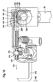
- FIG. 14 and Fig. 15 An advantageous embodiment, shown in Fig. 14 and Fig. 15 sees in that the drive element 152 has a toothed rack section 174, which engages with a drive pinion 176 of the actuator 170 stands.
- the actuator 170 further includes an actuating lever 178, with which via a freewheel 180 by pivoting the operating lever in one direction 182, the drive pinion 176 can be rotated such that this shifts the rack portion 174 in the direction 172 and thus counteracts the force of the elastic force accumulator to the Drive element 152 as far opposite to the activation direction 154 too move that the locking body 142 dips into the receptacle 162.
- the blocking device 140 is additionally with a locking device 190 is provided, which causes the drive element 152 remains in the inactive position.
- the latching device 190 comprises, for example, a latching pawl 192, which is provided with a latching lug 194, which in the inactive position of Drive element 152 engages behind a latching surface 196 thereof and thereby prevents the return of the drive member 152 to the active position.
- the detent pawl 192 is acted upon by means of a spring element 198 in such a way, that the locking lug 194 always in the inactive position of the drive element 152 engages behind the locking surface 196.
- the latch is with a sensing finger 200 provided by the end 136 of the hitch 30 is then acted upon when this is in the fixing position. In this position, the application of the tactile finger 200 causes by the End 136 of the trailer element 30, a displacement of the latch 192 against the action of the spring element 198 and thus in a position in which the latching lug 194 can not engage behind the latching surface 196.
Landscapes
- Engineering & Computer Science (AREA)
- Transportation (AREA)
- Mechanical Engineering (AREA)
- Agricultural Machines (AREA)
- Pivots And Pivotal Connections (AREA)
- Handcart (AREA)
- Motor Power Transmission Devices (AREA)
Abstract
Description
Die Erfindung betrifft eine Anhängekupplung für Kraftfahrzeuge umfassend ein fahrzeugfestes Lagerelement, ein gegenüber dem fahrzeugfesten Lagerelement von einer Arbeitsstellung in eine Ruhestellung und umgekehrt bewegbares Anhängeelement, welches eine Kupplungskugel und einen die Kupplungskugel an einem ersten Ende tragenden Kugelhals umfaßt, und eine Fixiereinrichtung, mit welcher das bewegbare Anhängeelement mindestens in der Arbeitsstellung an dem Lagerelement formschlüssig fixierbar ist.The invention relates to a towing hitch for motor vehicles comprising a vehicle-fixed bearing element, a relative to the vehicle-fixed bearing element from a working position to a rest position and vice versa movable Towing element, which is a coupling ball and a coupling ball At a first end bearing ball neck includes, and a Fixing device, with which the movable trailer element at least in the working position on the bearing element is positively fixed.
Derartige Anhängekupplungen sind aus der DE 100 17 013 bekannt.Such trailer couplings are known from DE 100 17 013.
Bei diesen Lösungen besteht aufgrund der Schwenkbarkeit des Anhängeelements um nur eine Schwenkachse das Problem, daß sich die Ausrichtung der einen Schwenkachse nicht auf alle Fahrzeugarten mit einer günstigen Kinematik anpassen läßt.These solutions exist due to the pivoting of the trailer element around only one pivot axis the problem that the alignment the one pivot axis not on all types of vehicles with a cheap Adapt kinematics.
Der Erfindung liegt daher die Aufgabe zugrunde, eine Anhängekupplung der gattungsgemäßen Art derart zu verbessern, daß diese hinsichtlich der Kinematik des Anhängeelements an die Raumverhältnisse einer möglichst großen Zahl von Kraftfahrzeugen anpaßbar ist. The invention is therefore based on the object, a trailer coupling of generic type to improve such that these with respect to the kinematics the trailer element to the spatial conditions of the largest possible Number of motor vehicles is adaptable.
Diese Aufgabe wird bei einer Anhängekupplung der eingangs beschriebenen Art erfindungsgemäß dadurch gelöst, daß das Anhängeelement relativ zum Lagerelement in einer Verschieberichtung zwischen einer das Anhängeelement gegenüber dem Lagerelement mehrachsig schwenkbar lagernden Schwenkstellung und einer das Anhängeelement gegenüber dem Lagerelement drehfest haltenden Fixierstellung verschiebbar ist.This object is achieved with a trailer coupling of the type described above Art according to the invention solved in that the trailer element relative to Bearing element in a direction of displacement between a trailer element with respect to the bearing element multiaxially pivoting pivotal position and a rotationally fixed to the trailer element relative to the bearing element holding fixation position is displaced.
Der Vorteil der erfindungsgemäßen Lösung ist darin zu sehen, daß aufgrund der mehrachsigen Schwenkbarkeit des Anhängeelements relativ zum Lagerelement in der Schwenkstellung in Verbindung mit einer Verschiebung des Anhängeelements relativ zum Lagerelement in die Schwenkstellung die für eine geeignete Bewegungskinematik des Anhängeelements zur Verfügung stehenden Freiheitsgrade größer sind und somit eine optimale Anpassung an unterschiedliche Raum- und Einbauverhältnisse erfolgen kann.The advantage of the solution according to the invention is the fact that due the multi-axis pivotability of the trailer relative to the bearing element in the pivot position in conjunction with a shift of Towing element relative to the bearing element in the pivot position for a suitable movement kinematics of the hitch element available standing degrees of freedom are greater and thus an optimal adaptation to different room and installation conditions can be done.
Besonders günstig ist es dabei, wenn das Anhängeelement in der Schwenkstellung mindestens um eine erste Schwenkachse und mindestens um eine quer zur ersten Schwenkachse verlaufende zweite Schwenkachse schwenkbar ist.It is particularly advantageous if the trailer element in the pivot position at least about a first pivot axis and at least one pivotable transverse to the first pivot axis extending second pivot axis is.
Durch eine derartige zweiachsige Verschwenkbarkeit ist eine Vielzahl von Bewegungsmöglichkeiten des Anhängeelements realisierbar.By such a biaxial pivotability is a variety of Movement possibilities of the trailer element feasible.
Noch vorteilhafter ist es, wenn das Anhängeelement in der Schwenkstellung um mehr als eine quer zur ersten Schwenkachse verlaufende Achse schwenkbar ist, so daß noch mehr Freiheitsgrade für eine geeignete Bewegungskinematik des Anhängeelements zur Verfügung stehen. It is even more advantageous if the trailer element in the swivel position pivotable by more than one transverse to the first pivot axis axis is, so that more degrees of freedom for a suitable motion kinematics of the hitch element are available.
Besonders einfach läßt sich die mehrachsige Verschwenkbarkeit des Anhängeelements relativ zum Lagerelement dann realisieren, wenn das Anhängeelement in der Schwenkstellung durch ein in dieser wirksames mehrachsiges Gelenksystem an dem Lagerelement gelagert ist.Particularly easy is the multi-axis pivotability of the trailer element relative to the bearing element then realize when the hitch in the pivoting position by an effective in this multi-axis Joint system is mounted on the bearing element.
Ein derartiges Gelenksystem kann in unterschiedlichster Art und Weise ausgeführt sein.Such a joint system can be used in many different ways be executed.
Eine konstruktiv besonders geeignete Ausführung sieht vor, daß das Gelenksystem mindestens einen Gelenkkörper und eine Gelenkkörperaufnahme umfaßt.A structurally particularly suitable embodiment provides that the joint system comprises at least one joint body and a joint body receptacle.
Der Gelenkkörper könnte dabei durch einzelne Achsen oder Wellen an der Gelenkkörperaufnahme gelagert sein. Besonders zweckmäßig ist es, wenn das Gelenksystem ein Kugelgelenk umfaßt.The joint body could thereby by individual axes or waves on the Be stored articulated body receptacle. It is particularly useful if the Joint system includes a ball joint.
Zweckmäßigerweise ist in diesem Fall der Gelenkkörper so ausgebildet, daß er mindestens einen Bereich mit einer Kugelaußenfläche umfaßt und daß die Gelenkaufnahme mindestens einen Bereich mit einer Kugelinnenfläche umfaßt.Appropriately, in this case, the joint body is formed so that he comprises at least one area with a spherical outer surface and that the Articular receiving at least a region having a spherical inner surface comprises.
Im Fall einer Ausbildung des Gelenksystems als Kugelgelenk wäre es grundsätzlich ausreichend, wenn der Gelenkkörper lediglich partiell Kugelaußenflächen trägt.In the case of a training of the joint system as a ball joint, it would be basically sufficient if the joint body only partially spherical outer surfaces wearing.
Aus Gründen einer einfachen Herstellbarkeit ist es jedoch besonders günstig, wenn der Gelenkkörper im wesentlichen ein Kugelkörper ist. For reasons of ease of manufacture, however, it is particularly favorable when the joint body is essentially a spherical body.
Ferner läßt sich die Bewegbarkeit des im wesentlichen als Kugelkörper ausgeführten Gelenkkörpers konstruktiv besonders einfach dann realisieren, wenn der im wesentlichen als Kugelkörper ausgeführte Gelenkkörper durch mindestens zwei auf gegenüberliegenden Seiten angeordnete Kugelkappenflächen der Gelenkkörperaufnahme mehrachsig gelenkig gelagert ist.Furthermore, the mobility of the essentially as a spherical body can be constructively realize the executed joint body in a particularly simple manner, when the substantially executed as a spherical body joint body through at least two spherical cap surfaces arranged on opposite sides the Gelenkkörperaufnahme is multi-axially articulated.
Prinzipiell ist bei einem Kugelgelenk der Gelenkkörper um eine Vielzahl von Schwenkachsen schwenkbar, so daß eine zusätzliche Verschwenkbarkeit des Anhängeelements relativ zum Gelenkkörper grundsätzlich nicht nötig wäre.In principle, in a ball joint of the joint body to a variety of Swiveling pivotally, so that an additional pivotability of the Trailer element relative to the joint body would not be necessary in principle.
Bei einer konstruktiv besonders einfach realisierbaren Lösung ist jedoch vorgesehen, daß das Anhängeelement gegenüber dem Gelenkkörper um die erste Schwenkachse drehbar ist.In a structurally particularly feasible solution is provided, however, that the trailer element relative to the joint body to the first Swivel axis is rotatable.
Ferner läßt sich die Verschiebbarkeit des Anhängeelements relativ zum Lagerelement besonders einfach dadurch lösen, daß das Anhängeelement relativ zum Gelenkkörper verschiebbar ist.Furthermore, the displaceability of the trailer element relative to the bearing element can be solve particularly simply by the fact that the trailer relative is displaceable to the joint body.
Alternativ oder ergänzend zum Vorsehen einer Verschiebbarkeit des Anhängeelements relativ zum Gelenkkörper wäre es auch denkbar, den Gelenkkörper zumindest über einen Teilweg, verschiebbar zu gestalten.Alternatively or in addition to providing a displaceability of the trailer element relative to the joint body, it would also be conceivable, the joint body at least over a partial route, to make it movable.
Aus Gründen einer möglichst einfachen Realisierbarkeit des mehrachsigen Gelenks ist es jedoch besonders günstig, wenn der Gelenkkörper ausschließlich gelenkig und unverschiebbar an dem Lagerelement gelagert ist. For the sake of the simplest possible feasibility of multi-axis Joint, however, it is particularly favorable when the joint body exclusively hinged and immovably mounted on the bearing element.
Die Verschiebbarkeit des Anhängeelements relativ zum Gelenkkörper läßt sich am einfachsten dadurch realisieren, daß das Anhängeelement mit einem Lagerabschnitt den Gelenkkörper in Richtung von dessen Längsachse durchsetzt.The displaceability of the trailer element relative to the joint body can be easiest way realize that the trailer with a Bearing portion passes through the joint body in the direction of its longitudinal axis.
Im Zusammenhang mit dem erfindungsgemäßen Gelenksystem wurde lediglich dessen Wirkung in der Schwenkstellung erläutert. Es wurden keinerlei Angaben zur Wirkung des Gelenksystems in der Fixierstellung gemacht.In connection with the joint system according to the invention was only its effect in the pivot position explained. There were none Information on the effect of the joint system made in the fixation position.
Grundsätzlich wäre es denkbar, das Gelenksystem auch in der Fixierstellung mit Kräften zu beaufschlagen und somit das Gelenksystem auch in der Fixierstellung zum Festlegen des Anhängeelements relativ zum Lagerelement heranzuziehen.In principle, it would be conceivable to use the joint system also in the fixing position to apply forces and thus the joint system in the fixation position to use for fixing the trailer element relative to the bearing element.
Der Aufbau des erfindungsgemäßen Gelenksystems läßt sich jedoch konstruktiv dann vereinfachen, wenn das Gelenksystem in der Fixierstellung im wesentlichen kräftefrei ist, denn dann kann das Gelenksystem so konzipiert werden, daß es keinerlei in der Fixierstellung und somit im Betrieb des Anhängeelements auftretenden Kräfte aufnehmen muß.However, the construction of the joint system according to the invention can be constructive then simplify when the articulation system in the fixation position in is essentially free of forces, because then the joint system can be designed that way be that there is no in the fixation position and thus in the operation of the Tow hitch must absorb forces occurring.
Um die Fixierung des Anhängeelements in der Fixierstellung relativ zum Lagerelement zu erreichen, ist vorzugsweise vorgesehen, daß das Anhängeelement in der Fixierstellung mit dem Lagerelement durch einen ersten Satz von Fixierelementen wechselwirkt, von denen ein erstes am Anhängeelement und ein zweites am Lagerelement angeordnet ist. To fix the attachment element in the fixing position relative to the bearing element to achieve, it is preferably provided that the trailer element in the fixing position with the bearing element by a first set of fixing elements interacts, of which a first on the hitch and a second is arranged on the bearing element.
Noch vorteilhafter ist es, wenn das Anhängeelement und das Lagerelement in der Fixierstellung durch einen zweiten Satz von Fixierelementen wechselwirkt, von denen ein erstes am Anhängeelement und ein zweites am Lagerelement angeordnet ist.It is even more advantageous when the trailer element and the bearing element in the fixing position interacts with a second set of fixing elements, of which a first on the trailer element and a second on the bearing element is arranged.
Um in einfacher Weise zu gewährleisten, daß das Gelenksystem in der Fixierstellung im wesentlichen kräftefrei ist, ist vorzugsweise vorgesehen, daß der erste Satz von Fixierelementen auf einer Seite des Gelenksystems und der zweite Satz von Fixierelementen auf der anderen Seite des Gelenksystems angeordnet ist, so daß in einfacher Weise das zwischen diesen liegende Gelenksystem von in der Fixierstellung beim Anhängerbetrieb wirkenden Kräften freigehalten werden kann.To ensure in a simple manner that the joint system in the fixing position is substantially free of forces, it is preferably provided that the first set of fixing elements on one side of the joint system and the second set of fixing elements on the other side of the joint system is arranged so that in a simple way lying between them Joint system of acting in the fixing position in trailer operation Forces can be kept free.
Die Fixierung des Anhängeelements relativ zum Lagerelement in der Fixierstellung läßt sich noch weiter verbessern, wenn das Anhängeelement und das Lagerelement in der Fixierstellung durch einen dritten Satz von Fixierelementen wechselwirken, von denen ein erstes am Anhängeelement und ein zweites am Lagerelement angeordnet ist.The fixation of the trailer relative to the bearing element in the fixing position can be further improved if the hitch and the Bearing element in the fixing position by a third set of fixing elements interact, of which a first on the hitch and a second is arranged on the bearing element.
Dabei könnte der dritte Satz von Fixierelementen dem ersten Satz von Fixierelementen zugeordnet sein und auf der selben Seite des Gelenksystems angeordnet sein wie der erste Satz von Fixierelementen.The third set of fixing elements could be the first set of fixing elements be assigned and arranged on the same side of the joint system be like the first set of fixation elements.
Besonders günstig ist es, wenn der dritte Satz von Fixierelementen auf der selben Seite des Gelenksystems angeordnet ist wie der zweite Satz von Fixierelementen. It is particularly favorable if the third set of fixing elements on the the same side of the joint system is arranged as the second set of fixing elements.
Bei der Zuordnung des dritten Satzes von Fixierelementen zum zweiten Satz von Fixierelementen sind ebenfalls unterschiedliche Lösungen denkbar.In the assignment of the third set of fixing elements to the second set of fixing elements are also different solutions conceivable.
Besonders vorteilhaft läßt sich die Abstützung des Anhängeelements relativ zum Lagerelement dann realisieren, wenn der zweite Satz von Fixierelementen und der dritte Satz von Fixierelementen auf einander gegenüberliegenden Seiten des Anhängeelements angeordnet sind.Particularly advantageous is the support of the trailer relative to realize the bearing element when the second set of fixing elements and the third set of fixing elements on opposite sides Sides of the hitch element are arranged.
Eine aus Gründen einer günstigen räumlichen Anordnung bevorzugte Lösung sieht vor, daß der dritte Satz von Fixierelementen im selben Bereich des Anhängeelements wirksam ist wie der zweite Satz von Fixierelementen.A preferred solution for reasons of a favorable spatial arrangement provides that the third set of fuser elements in the same area of Towing element is effective as the second set of fixing elements.
Um zusätzliche Maßnahmen zum Außereingriffbringen der Sätze von Fixierelementen zu vermeiden, ist vorzugsweise vorgesehen, daß die Fixierelemente durch Bewegen des Anhängeelements von der Fixierstellung in die Schwenkstellung außer Wechselwirkung bringbar sind.To additional measures to disengage the sets of fixing To avoid, it is preferably provided that the fixing by moving the hitch element from the fixing position into the pivoting position can be brought out of interaction.
Hinsichtlich der Ausbildung des ersten Satzes von Fixierelementen wurden bislang keine näheren Angaben gemacht. So sieht eine vorteilhafte Lösung vor, daß der erste Satz von Fixierelementen einen als erstes Formschlußelement am Anhängeelement angeordneten Fixierzapfen und als zweites Formschlußelement eine am Lagerelement angeordnete Zapfenaufnahme aufweist.With regard to the formation of the first set of fixing elements have been so far no details given. This is an advantageous solution before, that the first set of fixing elements as a first positive locking element on the trailer element arranged fixing pins and second Positive locking element arranged on the bearing element pin receptacle having.
Bei einer derartigen Ausbildung des ersten Satzes von Fixierelementen ist es günstig, wenn diese auf einer dem Kugelhals abgewandten Seite des Gelenksystems angeordnet ist. In such a design of the first set of fixing is favorable, if this on a side facing away from the ball neck of the joint system is arranged.
Besonders günstig läßt sich dabei die Wechselwirkung mit dem Gelenkkörper dann realisieren, wenn der Fixierzapfen den Gelenkkörper durchgreift und relativ zum Gelenkkörper in Richtung seiner Längsachse verschiebbar ist.The interaction with the joint body can be particularly favorable then realize when the fixing pin passes through the joint body and is displaceable relative to the joint body in the direction of its longitudinal axis.
Um eine optimale Fixierung des Anhängeelements in der Fixierstellung zu erreichen, hat es sich als besonders günstig erwiesen, daß das Anhängeelement in der Fixierstellung mit seinem der Kupplungskugel gegenüberliegenden Ende maximal über den Gelenkkörper übersteht und in der Schwenkstellung mit diesem Ende innerhalb einer Außenkontur des Gelenkkörpers liegt. Damit behindert das Ende des Anhängeelements in der Schwenkstellung die Verschwenkbewegung um die dem Gelenksystem zur Verfügung stehenden Achsen nicht und außerdem besteht in der Fixierstellung in einfacher Weise die Möglichkeit, den insbesondere zwischen dem Gelenksystem und diesem Ende liegenden Fixierzapfen ausreichend lang und somit stabil auszubilden und zu lagern.To an optimal fixation of the trailer in the fixing position reach, it has proved to be particularly favorable that the trailer element in the fixing position with its opposite of the coupling ball End maximally over the joint body protrudes and in the Pivoting position with this end within an outer contour of the joint body lies. This hinders the end of the hitch in the Swivel position, the pivoting movement to the joint system for Available axes not and also exists in the fixing position in a simple way, the possibility of particular between the joint system and this end lying Fixierzapfen sufficiently long and thus stable form and store.
Hinsichtlich der Fixierungswirkung des ersten Satzes von Formschlußelementen wurden bislang keine weiterführenden Angaben gemacht.With regard to the fixing effect of the first set of positive locking elements So far, no further information has been provided.
So ist es mindestens erforderlich, daß der erste Satz von Formschlußelementen das Anhängeelement relativ zum Lagerelement in mindestens einer Querrichtung quer zur Verschieberichtung festlegt.So it is at least necessary that the first set of positive locking elements the hitch relative to the bearing element in at least one Defines transverse direction transverse to the direction of displacement.
Noch vorteilhafter ist es, wenn der erste Satz von Formschlußelementen das Anhängeelement in mindestens zwei quer zueinander und quer zur Verschieberichtung laufenden Querrichtungen festlegt, so daß der erste Satz von Formschlußelementen maximal die Möglichkeit einer Drehbewegung um die Verschieberichtung zuläßt, im übrigen jedoch das Anhängeelement relativ zu dem Lagerelement fixiert.It is even more advantageous if the first set of interlocking elements the Towing element in at least two transverse to each other and transverse to the direction of displacement current transverse directions, so that the first set of Positive locking elements maximum the possibility of rotation about the Move direction allows, but otherwise the hitch relative to fixed to the bearing element.
Hinsichtlich des zweiten Satzes von Fixierelementen wurden bislang ebenfalls keine näheren Angaben gemacht. So sieht eine vorteilhafte Ausführungsform des zweiten Satzes von Fixierelementen vor, daß dieser einen Formschlußkörper und eine Formschlußkörperaufnahme aufweist.With regard to the second set of fixing elements have been so far as well no details provided. This is an advantageous embodiment of the second set of fixing before that this is a positive locking body and has a positive locking body receiving.
Prinzipiell ist eine beliebige Zuordnung der beiden relativ zu dem Lagerelement und dem Anhängeelement denkbar.In principle, any assignment of the two is relative to the bearing element and the trailer element conceivable.
Als besonders zweckmäßig hat es sich jedoch erwiesen, wenn der Formschlußkörper am Anhängeelement und die Formschlußkörperaufnahme am Lagerelement angeordnet ist.As particularly useful, it has been found, however, if the positive-locking body on the trailer element and the positive locking body receptacle on the bearing element is arranged.
Hinsichtlich der Ausbildung des Formschlußkörpers und der Formschlußkörperaufnahme wurden bislang keine näheren Angaben gemacht. So hat es sich als vorteilhaft erwiesen, wenn eines der Fixierelemente des zweiten Satzes von Fixierelementen in einem Winkel zueinander verlaufende Formschlußelemente aufweist.With regard to the formation of the positive-locking body and the positive-locking body receptacle So far no details have been given. That's how it turned out proven advantageous when one of the fixing elements of the second set of Fixing elements at an angle to each other positive locking elements having.
Besonders günstig ist es, wenn beide Fixierelemente des zweiten Satzes von Fixierelementen in einem Winkel zueinander verlaufende Formschlußflächen aufweisen. It is particularly favorable if both fixing elements of the second set of Fixing elements at an angle to each other extending positive engagement surfaces exhibit.
Die Formschlußflächen können dabei grundsätzlich beliebig orientiert sein. Als zweckmäßig hat es sich erwiesen, wenn die Formschlußflächen in der Verschieberichtung mit zunehmender Erstreckung in dieser aufeinander zu verlaufen.The form-locking surfaces can basically be oriented arbitrarily. When It has proved expedient if the positive-locking surfaces in the direction of displacement with increasing extent in this run towards each other.
Hinsichtlich der Wirkung der zweiten Formschlußelemente wurden bislang keine näheren Angaben gemacht. Besonders günstig ist es, wenn die zweiten Formschlußelemente das Anhängeelement gegenüber dem Lagerelement drehfest festlegen und somit sich hinsichtlich ihrer Wirkung mit den ersten Formschlußelementen ergänzen.With regard to the effect of the second positive locking elements have been so far no details provided. It is particularly favorable if the second Positive locking elements the trailer element relative to the bearing element rotatably set and thus in terms of their impact with the first Complement positive locking elements.
Besonders zweckmäßig ist es, wenn zur drehfesten Festlegung auch noch eine Festlegung quer zur Verschieberichtung erfolgt.It is particularly useful when the non-rotatable down another Determined transversely to the direction of displacement.
Um das Anhängeelement möglichst spielfrei in dem Lagerelement zu fixieren, ist es besonders günstig, wenn der zweite Satz von Formschlußelementen in einer quer zur Verschieberichtung verlaufenden Querrichtung eine Schwerkraft erzeugt, die die Möglichkeit schafft, eine in der Fixierstellung möglichst große Spielfreiheit zu erreichen.In order to fix the trailer element as free of play as possible in the bearing element, it is particularly advantageous if the second set of interlocking elements in a transverse direction transverse to the direction of a gravitational force generated, which creates the possibility of a possible in the fixation position as large To achieve freedom of play.
Hinsichtlich der Anordnung des zweiten Satzes von Formschlußelementen wurden bislang keine detaillierten Angaben gemacht.With regard to the arrangement of the second set of positive locking elements So far, no detailed information has been provided.
So ist es besonders günstig, wenn der zweite Satz von Fixierelementen derart angeordnet ist, daß dieser in der Fixierstellung auf einer in Fahrtrichtung rückwärtigen Seite des Lagerelementes und des Anhängeelements wirksam ist. So it is particularly advantageous if the second set of fixing such is arranged that this in the fixing position on a rearward in the direction of travel Side of the bearing element and the trailer element is effective.
Ferner ist es günstig, wenn in der Fixierstellung der zweite Satz von Fixierelementen im Bereich nahe eines zweiten Endes des Kugelhalses wirksam ist.Furthermore, it is favorable if, in the fixing position, the second set of fixing elements in the region near a second end of the ball neck is effective.
Ferner sieht eine vorteilhafte Lösung vor, daß das am Anhängeelement angeordnete Fixierelement im Bereich einer zum zweiten Ende des Kugelhalses hin verlaufenden Umbiegung des Kugelhalses angeordnet ist.Furthermore, an advantageous solution provides that arranged on the trailer element Fixing element in the area of a to the second end of the ball neck extending bend of the ball neck is arranged.
Hinsichtlich der Ausbildung des dritten Satzes von Fixierelementen wurden bislang ebenfalls keine näheren Angaben gemacht.With regard to the training of the third set of fixing elements have been so far no further details.
So sieht ein besonders vorteilhaftes Ausführungsbeispiel vor, daß der dritte Satz von Fixierelementen einen am Anhängeelement angeordneten Formschlußkörper und eine am Lagerelement angeordnete Formschlußaufnahme umfaßt.Thus, a particularly advantageous embodiment provides that the third Set of fixing a arranged on the hitch form fit body and a bearing element arranged on the form-locking receptacle includes.
Besonders vorteilhaft ist der dritte Satz von Fixierelementen dann angeordnet, wenn dieser in der Fixierstellung auf einer in Fahrtrichtung vorderen Seite des Lagerelements und des Anhängeelements angeordnet ist.Particularly advantageously, the third set of fixing elements is then arranged if this in the fixing position on a front in the direction of travel Bearing element and the trailer element is arranged.
Besonders zweckmäßig sind der dritte Satz von Fixierelementen und der zweite Satz von Fixierelementen dann einsetzbar, wenn diese in der Fixierstellung das Anhängeelement quer zur Verschieberichtung im wesentlichen spielfrei fixierend ausgebildet sind.Particularly useful are the third set of fixing and the second set of fixing then used when this in the fixing position the trailer element transversely to the direction of displacement substantially are formed fixing free of play.
Dies läßt sich insbesondere dadurch günstig erreichen, daß in der Fixierstellung der zweite Satz von Fixierelementen das Anhängeelement in diesem Bereich mit einer quer zur Verschieberichtung weisenden Kraftkomponente beaufschlagt. This can be achieved in particular by the fact that in the fixing position the second set of fixing elements the hitch in this Area with a direction transverse to the direction of force component applied.
Im Hinblick auf eine Festlegung des Anhängeelements in der Fixierstellung relativ zum Lagerelement wurden bislang keine näheren Angaben gemacht. So sieht eine besonders günstige Lösung vor, daß die Fixiereinrichtung eine Blockiereinrichtung aufweist, die ein Bewegen des Anhängeelements relativ zum Lagerelement in der Verschieberichtung blockiert.With regard to a definition of the trailer element in the fixing position relative to the bearing element so far no details have been made. So provides a particularly favorable solution that the fixing a Blocking device, which is a moving of the trailer relative blocked to the bearing element in the direction of displacement.
Die Blockiereinrichtung kann prinzipiell in unterschiedlichster Art und Weise ausgebildet sein. Eine besonders günstige Lösung sieht vor, daß die Blockiereinrichtung einen an einem der Elemente angeordneten Sperrkörper aufweist, welcher in eine eine Sperrfläche am anderen Element hintergreifende Position bringbar ist.The blocking device can in principle in a variety of ways be educated. A particularly favorable solution provides that the blocking device has a blocking body arranged on one of the elements, which in a locking surface behind the other element engages behind position can be brought.
Besonders vorteilhaft ist eine Blockiereinrichtung, bei welcher der Sperrkörper von einer Freigabestellung kraftbeaufschlagt in einer Bewegungsrichtung in die Sperrstellung bewegbar ist.Particularly advantageous is a blocking device, wherein the blocking body from a release position kraftbeaufschlagt in a direction of movement in the Locking position is movable.
Um den Sperrkörper mit der Kraft zur Bewegung desselben in Richtung der Sperrstellung zu beaufschlagen, ist zweckmäßigerweise vorgesehen, daß die Blockiereinrichtung einen Sperrkörperantrieb aufweist, mit welchem der Sperrkörper mit einer diesen von der Freigabestellung in Richtung der Sperrstellung bewegenden Kraft beaufschlagbar ist.To the lock body with the force to move it in the direction of To apply locking position, it is expediently provided that the Blocking device has a blocking body drive, with which the locking body with this one of the release position in the direction of the blocking position moving force is acted upon.
Vorzugsweise ist der Sperrkörperantrieb dabei so ausgebildet, daß er ein Antriebselement aufweist, mit welchem der Sperrkörper von der Freigabestellung in die Sperrstellung bewegbar ist. Preferably, the blocking body drive is designed so that it is a Drive element having, with which the locking body of the release position is movable in the locked position.
Dieses Antriebselement kann in unterschiedlichster Art und Weise angetrieben sein.This drive element can be driven in various ways be.
Eine günstige Lösung sieht vor, daß das Antriebselement durch einen elastischen Kraftspeicher beaufschlagt ist.A favorable solution provides that the drive element by a elastic force storage is applied.
Besonders günstig ist es im vorliegenden Fall, wenn der Sperrkörper und der Sperrkörperantrieb in dem Lagerelement angeordnet sind, da dieses fahrzeugfest angeordnet ist und sich somit auch der Sperrkörperantrieb fahrzeugfest anordnen läßt.It is particularly favorable in the present case, when the locking body and the Locking body drive are arranged in the bearing element, as this vehicle-fixed is arranged and thus also the locking body drive fixed to the vehicle can arrange.
Vorzugsweise ist vorgesehen, daß in dem Lagerelement der Sperrkörper zwischen der Freigabestellung und der Sperrstellung in der Bewegungsrichtung quer zur Verschieberichtung bewegbar ist.It is preferably provided that in the bearing element of the locking body between the release position and the blocking position in the direction of movement is movable transversely to the direction of displacement.
Zweckmäßigerweise ist in diesem Fall vorgesehen, daß das Antriebselement in einer quer zur Bewegungsrichtung verlaufenden Aktivierungsrichtung verschiebbar im Lagerelement angeordnet ist.Appropriately, it is provided in this case that the drive element in a transversely to the direction of movement extending activation direction is arranged in the bearing element.
Eine besonders zweckmäßige Ausbildung des Antriebselements sieht vor, daß dieses eine Antriebskulisse mit einer Aufnahme aufweist, in welcher der Sperrkörper in der Freigabestellung eintaucht, und mit einer Verschiebefläche, mit welcher der Sperrkörper von der Freigabestellung in die Sperrstellung bewegbar ist.A particularly useful embodiment of the drive element provides that this has a drive link with a receptacle in which the locking body immersed in the release position, and with a sliding surface, with which of the blocking body from the release position into the blocking position movable is.
Die Blockiereinrichtung kann grundsätzlich lediglich die Fixierstellung blockieren und somit das Anhängeelement in dieser halten. The blocking device can basically only the fixing position block and thus hold the hitch in this.
Um das Anhängeelement jedoch spielfrei in dem Lagerelement zu fixieren ist es besonders vorteilhaft, wenn die Blockiereinrichtung in der Sperrstellung des Sperrkörpers aufgrund von dessen Zusammenwirken mit der Sperrfläche das Anhängeelement in Richtung der Fixierstellung kraftbeaufschlagt.However, in order to fix the trailer element free of play in the bearing element it is particularly advantageous if the blocking device in the locked position of Block body due to its interaction with the blocking surface of the Towing element in the direction of the fixing force-loaded.
Eine derartige Beaufschlagung führt vorzugsweise dazu, daß die Blockiereinrichtung zumindest einen Teil der Sätze von Fixierelementen in spielfreier Anlage hält.Such loading preferably leads to the fact that the blocking device at least a portion of the sets of fixing in play free Plant stops.
Da sich jedoch beim Betrieb des Fahrzeugs stets noch nachträglich durch Verschleiß ein Spiel einstellen kann, ist es besonders günstig, wenn die Blockiereinrichtung auf den mindestens einen Teil der Sätze von Fixierelementen spielfrei nachstellend wirkt.However, since the operation of the vehicle always subsequently by wear can adjust a game, it is particularly favorable when the blocking device on the at least part of the sets of fixing elements backlash-free acts.
Ein derartiges spielfreies nachstellendes Einwirken läßt sich insbesondere dadurch erreichen, daß die Sperrfläche schräg zur Verschieberichtung verläuft.Such a backlash-free adjusting action can be in particular achieve that the blocking surface extends obliquely to the direction of displacement.
Ferner ist es zweckmäßig, wenn sich an die Verschiebefläche des Antriebselements eine Keilfläche anschließt, welche den Sperrkörper in Richtung der Sperrstellung nachstellend beaufschlagt, so daß auch bei einer verschleißbedingten Nachstellbewegung des Sperrkörpers auf der Sperrfläche die Kraftbeaufschlagung des Sperrkörpers aufgrund der Keilfläche erhalten bleibt.Furthermore, it is expedient if the displacement of the drive element a wedge surface connects, which the blocking body in the direction of Adjacent blocking position acted upon, so that even with a wear-related Nachstellbewegung the locking body on the blocking surface, the application of force the locking body is retained due to the wedge surface.
Hinsichtlich der Möglichkeit, die Sperrstellung des Sperrkörpers zu lösen, wurden bislang keine näheren Angaben gemacht. So sieht eine vorteilhafte Lösung vor, daß die Blockiereinrichtung eine auf den Sperrkörperantrieb wirkende Betätigungseinrichtung umfaßt, mit welcher auf das Antriebselement entgegen der Kraftwirkung des elastischen Kraftspeichers einwirkbar ist.With regard to the possibility of releasing the blocking position of the blocking body, So far no details have been given. So looks a beneficial Solution before that the blocking device on the blocking body drive acting actuator comprises, with which on the drive element can be acted upon contrary to the force effect of the elastic force accumulator.
Eine derartige Betätigungseinrichtung ist vorzugsweise mit einem Betätigungselement versehen.Such an actuating device is preferably provided with an actuating element Mistake.
Ferner ist es günstig, wenn die Betätigungseinrichtung einen Freilauf aufweist, welcher es zuläßt, daß das Betätigungselement in seine Ausgangsstellung zurückkehrt, obwohl der Sperrkörperantrieb in seiner inaktiven Stellung steht.Furthermore, it is favorable if the actuating device has a freewheel, which allows it, that the actuating element in its starting position returns, although the blocking body drive is in its inactive position.
Darüber hinaus sieht eine vorteilhafte Ausführungsform der erfindungsgemäßen Anhängekupplung vor, daß der Sperrkörperantrieb eine Rasteinrichtung aufweist, welche das Antriebselement in seiner inaktiven Stellung hält, so lange das Anhängeelement außerhalb der Fixierstellung steht.In addition, an advantageous embodiment of the invention provides Towbar before that the locking body drive a locking device having the drive element in its inactive position holds, as long as the hitch is outside the fixing position.
Eine derartige Rasteinrichtung schafft die Möglichkeit, die durch die Betätigungseinrichtung erreichbare inaktive Stellung des Antriebselements für den Sperrkörper so lange aufrecht zu erhalten, bis das Anhängeelement wieder in der Fixierstellung steht und erst dann in der Fixierstellung wiederum durch die Blockiereinrichtung in dieser blockiert werden kann.Such a latching device creates the possibility that by the Actuator achievable inactive position of the drive element for to maintain the lock body so long until the hitch again in the fixation position and only then in the fixation position again can be blocked by the blocking device in this.
Vorzugsweise ist dabei die Rasteinrichtung so ausgebildet, daß das Antriebselement bei Erreichen der Fixierstellung durch das Anhängeelement die inaktive Stellung wieder verläßt und wiederum den Sperrkörper in Richtung der Sperrstellung beaufschlagt, so daß das Antriebselement wieder in die aktive Stellung übergeht. Preferably, the latching device is designed so that the drive element upon reaching the fixing position by the trailer element the Inactive position leaves again and turn the blocking body in the direction the blocking position acted upon, so that the drive element back into the active position passes.
Weitere Merkmale und Vorteile der Erfindung sind Gegenstand der nachfolgenden Beschreibung sowie der zeichnerischen Darstellung einiger Ausführungsbeispiele.Further features and advantages of the invention are the subject of the following Description and the drawings of some embodiments.
In der Zeichnung zeigen:
- Fig. 1
- ein Ausführungsbeispiel einer in einem Heckbereich einer Fahrzeugkarosserie montierten erfindungsgemäßen Anhängekupplung in Seitenansicht;
- Fig. 2
- eine perspektivische Darstellung des Ausführungsbeispiels mit transparent gezeichnetem Stoßfänger;
- Fig. 3
- eine Draufsicht in Richtung des Pfeils H in Fig. 1 mit transparent gezeichnetem Stoßfänger;
- Fig. 4
- eine Ansicht in Richtung des Pfeils S in Fig. 3;
- Fig. 5
- eine Darstellung einer erfindungsgemäßen Anhängekupplung in einer Schwenkstellung des Anhängeelements im Schnitt längs Linie 5-5 in Fig. 3;
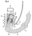
- Fig. 6
- eine Darstellung ähnlich Fig. 5 längs Linie 6-6 in Fig. 3;
- Fig. 7
- eine Darstellung der erfindungsgemäßen Anhängekupplung mit in Fixierstellung stehendem Anhängeelement ähnlich Fig. 6;
- Fig. 8
- eine Seitenansicht ähnlich Fig. 7 des Anhängeelements;
- Fig. 9
- einen Schnitt längs Linie 9-9 in Fig. 8;
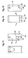
- Fig. 10
- eine Ansicht des erfindungsgemäßen Lagerelements in Richtung des Pfeils V in Fig. 11;
- Fig. 11
- eine Ansicht des erfindungsgemäßen Lagerelements in Richtung des Pfeils R in Fig. 10;
- Fig. 12
- eine Ansicht des erfindungsgemäßen Lagerelements in Richtung des Pfeils L in Fig. 10;
- Fig. 13
- einen Schnitt längs Linie 13-13 in Fig. 7;
- Fig. 14
- einen Schnitt längs Linie 14-14 in Fig. 13 im Bereich des Lagerelements mitsamt einer perspektivischen Darstellung einer erfindungsgemäßen Betätigungseinrichtung und einer Rasteinrichtung und
- Fig. 15
- eine Draufsicht in Richtung des Pfeils O in Fig. 14.
- Fig. 1
- an embodiment of a mounted in a rear region of a vehicle body according to the invention hitch in side view;
- Fig. 2
- a perspective view of the embodiment with transparently drawn bumper;
- Fig. 3
- a plan view in the direction of the arrow H in Figure 1 with transparently drawn bumper.
- Fig. 4
- a view in the direction of the arrow S in Fig. 3;
- Fig. 5
- an illustration of a trailer coupling according to the invention in a pivoting position of the trailer element in section along line 5-5 in Fig. 3;
- Fig. 6
- a representation similar to Figure 5 along line 6-6 in Fig. 3.
- Fig. 7
- a representation of the trailer coupling according to the invention with standing in fixing position trailer element similar to FIG. 6;
- Fig. 8
- a side view similar to Figure 7 of the trailer element.
- Fig. 9
- a section along line 9-9 in Fig. 8;
- Fig. 10
- a view of the bearing element according to the invention in the direction of the arrow V in Fig. 11;
- Fig. 11
- a view of the bearing element according to the invention in the direction of arrow R in Fig. 10;
- Fig. 12
- a view of the bearing element according to the invention in the direction of the arrow L in Fig. 10;
- Fig. 13
- a section along line 13-13 in Fig. 7;
- Fig. 14
- a section along line 14-14 in Figure 13 in the region of the bearing element together with a perspective view of an actuating device according to the invention and a locking device and
- Fig. 15
- a plan view in the direction of arrow O in Fig. 14.
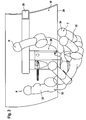
Ein Ausführungsbeispiel einer erfindungsgemäßen Anhängekupplung, dargestellt
in Fig. 1, ist an einer Karosserie 10 eines Kraftfahrzeugs in einem
Heckbereich 12 montierbar, und umfaßt ein Lagerelement 20, welches
zwischen einer Rückseite 14 eines unteren Heckbereichs 16 und einem
Stoßfänger 18 montierbar ist. An embodiment of a trailer coupling according to the invention, shown
in Fig. 1, is on a
Das Lagerelement 20 liegt dabei im wesentlichen vollständig in einem
Zwischenraum 22 zwischen dem Stoßfänger 18 und der Rückseite 14 des
unteren Heckbereichs 16, und zwar vorzugsweise oberhalb einer Unterkante
24 des Stoßfängers 18 und oberhalb einer Unterseite 26 der Karosserie 10,
welche sich an die Rückseite 14 anschließt.The bearing
Vorzugsweise ist dabei das Lagerelement 20 an einem zumindest bereichsweise
parallel zum Stoßfänger 18 verlaufenden Querträger 28 gehalten.Preferably, the bearing
An dem Lagerelement 20 ist ferner ein als Ganzes mit 30 bezeichnetes
Anhängeelement gehalten, welches einen Kugelhals 32 aufweist, der an einem
ersten Ende 36 eine Kupplungskugel 34 trägt und, wie in Fig. 2 bis 4 dargestellt,
von einer Arbeitsstellung A in eine Tauchstellung T bewegbar ist, in
welcher die Kupplungskugel 34 unter der Unterkante 24 des Stoßfängers 18
hindurchbewegbar ist und dann von der Tauchstellung T in eine Ruhestellung R
bewegbar ist, in welcher die Kupplungskugel 34 im wesentlichen mitsamt dem
Kugelhals in dem Zwischenraum 22 zwischen dem Stoßfänger 18 und der
Rückseite 14 des unteren Heckbereichs 16 angeordnet ist.On the bearing
Dabei ist das Anhängeelement 30 gegenüber dem Lagerelement 20 in der
Arbeitsstellung A und der Ruhestellung R in einer Fixierstellung angeordnet,
während das Verschwenken zwischen der Arbeitsstellung A und der Ruhestellung
R in einer Schwenkstellung des Anhängeelements 30 relativ zum
Lagerelement 20 erfolgt. In this case, the
In der Schwenkstellung, dargestellt in Fig. 5 und Fig. 6, und zwar anhand der
sich unmittelbar aus der Arbeitsstellung A ergebenden Schwenkstellung, ist
das Anhängeelement 30 mittels eines zumindest zweiachsig schwenkbaren
Gelenks 40 gegenüber dem Lagerelement 20 schwenkbar gelagert, wobei das
zweiachsig schwenkbare Gelenk 40 zumindest eine Schwenkbewegung um
eine erste Schwenkachse 42 und eine senkrecht zu dieser verlaufende
Schwenkachse 44 erlaubt.In the pivoting position, shown in Fig. 5 and Fig. 6, and with reference to the
is directly from the working position A resulting pivot position is
the
Die erste Schwenkachse 42 ist festgelegt durch ein erstes Schwenkgelenk 46,
mit welchem das Anhängeelement 30 gegenüber einem Gelenkkörper 50 des
zweiachsigen Gelenks 40 schwenkbar ist und verläuft zumindest in der
Arbeitsstellung A und der Ruhestellung R, noch besser in allen Stellungen des
Anhängeelements 30, quer zu einer Fahrbahnoberfläche 48.The
Dieses erste Schwenkgelenk 46 wird beispielsweise gebildet durch einen im
Gelenkkörper 50 vorgesehenen Durchbruch 52 mit zur ersten Schwenkachse
42 zylindrischen Mantelflächen 54 und durch einen Lagerzapfen 56 mit einer
zur ersten Schwenkachse 42 zylindrischen Außenfläche 58, so daß der Lagerzapfen
56 in dem Durchbruch 52 frei gegenüber dem Gelenkkörper 50 drehbar
ist.This first pivot joint 46 is formed for example by a in
Die zweite Schwenkachse 44 wird bei dem dargestellten Ausführungsbeispiel
gebildet durch eine gelenkige Lagerung des Gelenkkörpers 50 in einem von
dem Lagerelement 20 gebildeten Gelenkgehäuse 60. The
Bei dem dargestellten Ausführungsbeispiel ist der Gelenkkörper 50 als Kugel
ausgebildet und weist eine Kugelaußenfläche 62 auf, welche in einer vom
Gelenkgehäuse 60 gebildeten Gelenkpfanne 64 durch deren Kugelinnenfläche
66 drehbar gelagert ist.In the illustrated embodiment, the
Vorzugsweise liegt die Kugelinnenfläche 66 an der Kugelaußenfläche 62 in
einem zur Schwenkachse 42 äquatorialen Bereich 68 der Kugelaußenfläche 62
an und führt somit die als Gelenkkörper 50 dienende Gelenkkugel unter
anderem um die den äquatorialen Bereich 68 schneidende und senkrecht zur
ersten Schwenkachse 42 verlaufende zweite Schwenkachse 44, und zusätzlich
auch um eine beliebige Zahl weiterer, senkrecht zur ersten Schwenkachse 42
verlaufender Schwenkachsen, bedingt durch die Lagerung des Gelenkkörpers
50 als Gelenkkugel in der Gelenkpfanne 64 in Form eines als Ganzes mit 70
bezeichneten Kugelgelenks.Preferably, the ball
Die Gelenkpfanne 64 wird vorzugsweise gebildet durch einen Formkörper 72
des Lagerelements 20, welcher an dem Querträger 28 gehalten ist, wobei ein
Teil der Gelenkpfanne 64 einerseits durch einen unteren Bereich 74 einer Ausnehmung
76 im Formkörper 72 gebildet ist, und andererseits durch einen in
die Ausnehmung 76 eingesetzten Einsatzkörper 80, welcher mit seiner der
Gelenkkugel 50 zugewandten Stirnseite 82 die Kugelinnenfläche 66 des
unteren Bereichs 74 der Ausnehmung 76 vervollständigt.The
Der Einsatzkörper 80 ist dabei in der Ausnehmung 76 fest angeordnet, so daß
die Gelenkkugel 50 zwischen dem unteren Bereich 74 der Ausnehmung 76 und
der Stirnseite 82 des Einsatzkörpers 80 geführt ist. The
Der Einsatzkörper 80 weist ferner einen zentralen Durchbruch 84 auf, welcher
so angeordnet ist, daß mit diesem der Durchbruch 52 der Gelenkkugel 50
fluchtend ausgerichtet werden kann und somit der Lagerzapfen 56 in den
Durchbruch 84 durch Verschieben des Lagerzapfens 56 in Richtung seiner
Längsachse 78 und somit bei dieser Ausrichtung der Gelenkkugel 50 auch
längs der ersten Schwenkachse 42 mit einem einen Fixierzapfen 86 bildenden
oberen Bereich eingeschoben werden kann, wie in Fig. 8 dargestellt.The
Der den Durchbruch 84 umfassenden Teil des Einsatzkörpers 80 bildet somit
eine Aufnahme 90 für den als Fixierzapfen 86 über die Gelenkkugel 50 überstehenden
Teil des Lagerzapfens 56, welcher in der Aufnahme 90 quer zur
ersten Schwenkachse 42 durch Verschieben des Lagerzapfens 56 in Richtung
der ersten Schwenkachse 42 in der in Fig. 8 dargestellten Fixierstellung fixierbar
ist.The
Damit kann sich der Lagerzapfen 56 lediglich noch um die erste Schwenkachse
42 jedoch nicht mehr um die zweite Schwenkachse 44 drehen, da diesbezüglich
auch die Gelenkkugel 50 durch den Lagerzapfen 56 festgelegt ist.Thus, the bearing
Ferner erfolgt eine weitere Fixierung des Anhängeelements 30 in dem Lagerelement
20 durch einen an das Anhängeelement 30 angeformten Formschlußkörper
100, welcher wie in Fig. 9 und 10 dargestellt, zwei keilförmig zueinander
verlaufende Formschlußflächen 102 und 104 umfaßt. Der Formschlußkörper
100 ist dabei im Bereich eines Übergangs von dem Lagerzapfen 56 zu
dem Kugelhals 32, vorzugsweise nahe einem zweiten Ende 38 des Kugelhalses
32 angeordnet, und zwar in einem Bereich einer Innenseite 108 einer Umbiegung
106 des Kugelhalses 32, welche sich unmittelbar an das zweite
Ende 38 anschließt, so daß sich an der Innenseite 108 die Formschlußflächen
102 und 104 zu einer die Innenseite 108 bildenden Kante vereinigen, welche
quer zur Längsrichtung 78 des Lagerzapfens 56 verläuft, vorzugsweise in
einem stumpfen Winkel von mehr als ungefähr 90°.Furthermore, there is a further fixation of the
Ferner ist der Formkörper 72 des Lagerelements 20 mit einer Aufnahme 110
für den Formschlußkörper 100 versehen, welche Formschlußflächen 112 und
114 aufweist, an welchen bei in die Fixierstellung eingeschobenem Lagerzapfen
56 die Formschlußflächen 102 und 104 anliegen, die aufgrund ihres keilförmigen
Verlaufs dazu beitragen, das Anhängeelement 30 drehfest gegenüber
dem Lagerelement 20, und somit insbesondere gegen eine Drehung um die
erste Schwenkachse 42 gesichert, zu fixieren.Furthermore, the shaped
Schließlich ist das Anhängeelement 30 auf seiner dem Formschlußkörper 100
abgewandten und somit auf einer Außenseite der Umbiegung 106 angeordneten
Seite mit einem zweiten Formschlußkörper 120 versehen, welcher
eine flache, vorzugsweise parallel zur Längsachse 78 des Lagerzapfens 56
verlaufende Formschlußfläche 122 aufweist.Finally, the
Diese Formschlußfläche 122 ist, wie in Fig. 11 dargestellt, an einer der
Aufnahme 110 gegenüberliegenden Seite vorgesehenen zweiten Formschlußaufnahme
130 anlegbar, welche ebenfalls eine der Formschlußfläche 122
entsprechende ebenfalls flache Formschlußfläche 132 aufweist, welche der
Aufnahme 110 zugewandt und auf einer dem Einsatzkörper 80 gegenüberliegenden
Seite der Gelenkkugel 50 angeordnet ist. This
Auch der zweite Formschlußkörper 120 und die zweite Formschlußaufnahme
130 sind aufgrund ihrer parallelen Ausrichtung zur Längsachse 78 und somit
auch zur ersten Schwenkachse 42 durch Verschieben des Lagerzapfens 56 in
einer in Richtung seiner Längsachse 78 verlaufenden Verschieberichtung 133
von der Schwenkstellung in die Fixierstellung miteinander in Eingriff bringbar.Also, the second
Vorzugsweise bilden einerseits die Formschlußflächen 112 und 114 mit der
Formschlußfläche 132 eine Art keilförmige Aufnahme, in welche die Formschlußflächen
102 und 104 des ersten Formschlußkörpers sowie die Formschlußfläche
122 des zweiten Formschlußkörpers 120 ebenfalls als eine Art Keil
einschiebbar und durch eine Bewegung in der Verschieberichtung 133 zu der
Fixierstellung hin spielfrei miteinander verkeilbar sind.Preferably, on the one hand form the form-locking
Vorzugsweise ist hierzu der zweite Formschlußkörper 120 derart ausgebildet,
daß dessen Formschlußfläche 122 senkrecht zu einer Krümmungsebene 134
des Kugelhalses 32 verläuft und in einem Abstand von der zweiten Schwenkachse
42, welcher gleich oder größer ist als ein Radius der Außenfläche 58 des
Lagerzapfens 56.For this purpose, the second positive-locking
Beim Übergang von der in Fig. 7 dargestellten Fixierstellung in die in Fig. 5 und
6 dargestellte Schwenkstellung läßt sich nunmehr der Lagerzapfen 56 derart
entgegengesetzt zur Verschieberichtung 133 verschieben, daß der Fixierzapfen
86 den Durchbruch 84 verläßt und in den Durchbruch 52 der Gelenkkugel 50
eintritt, wobei ein Ende 136 des Lagerzapfens 56 innerhalb der Kugelaußenfläche
62 der Gelenkkugel 50 liegt oder diese maximal berührt, so daß die
Gelenkkugel 50 frei in allen Richtungen in der Gelenkpfanne 64 drehbar ist und
zusätzlich noch der Lagerzapfen 56 um die erste Schwenkachse 42 in dem
Durchbruch 52 relativ zur Gelenkkugel 50 drehbar ist. In the transition from the fixing position shown in Fig. 7 in the in Fig. 5 and
6 illustrated pivot position can now be the bearing
Damit läßt sich, wie insbesondere in Fig. 3 erkennbar, der Lagerzapfen 56 um
die zweite Schwenkachse 44 in Richtung einer der Ruhestellung R gegenüberliegenden
Seite mit seinem sich an das zweite Ende 38 des Kugelhalses 32
anschließenden Bereich verschwenken und zusätzlich noch um die erste
Schwenkachse 42 drehen, woraus die in Fig. 3 dargestellte Tauchstellung T
des Anhängeelements 30 resultiert.This can be, as can be seen in particular in Fig. 3, the bearing
Dies wird insbesondere noch dadurch erleichtert, daß, wie in Fig. 11 dargestellt,
der Formkörper 72 auf dieser Seite mit einem hochgezogenen Ausschnitt
138 zwischen der zweiten Formschlußaufnahme 130 und der ersten
Formschlußaufnahme 110 versehen ist, welcher eine Schwenkbewegung der
ersten Schwenkachse 42 um die zweite Schwenkachse 44 um beispielsweise
mehr als 40°, noch besser mehr als 45° erlaubt.This is facilitated in particular by the fact that, as shown in FIG. 11,
the molded
Zum Festlegen des Anhängeelements 30 in der Ruhestellung R ist, wie in
Fig. 12 dargestellt, das Lagerelement 20 auf seiner der Ruhestellung R
zugewandten Seite mit einem Ausschnitt 124 versehen, welcher Anlageflächen
126 und 128 aufweist, an welchen die Formschlußflächen 102 und 104 des
ersten Formschlußkörpers 100 in der Ruhestellung R anlegbar sind, um eine
um die erste Schwenkachse 42 drehfeste Fixierung des Anhängeelements 30
in der Ruhestellung R zu erreichen.To set the
Um ein Lösen des Fixierzapfens 86 aus der Fixierstellung zu verhindern, ist,
wie in Fig. 7 und 13 dargestellt, eine als Ganzes mit 140 bezeichnete Blockiereinrichtung
vorgesehen, welche einen Sperrkörper 142 aufweist, der in einer
Bewegungsrichtung 148 zwischen einer in Fig. 7 dargestellten Sperrstellung
und einer in Fig. 13 dargestellten Freigabestellung hin und her bewegbar ist. In order to prevent a loosening of the fixing
In der in Fig. 7 dargestellten Sperrstellung hintergreift der Sperrkörper 142
eine am Fixierzapfen 86 vorgesehene Sperrfläche 144, welche schräg zur
Längsachse 78 verläuft und in der Fixierstellung auf einer Seite des Sperrkörpers
142 angeordnet ist, welche der Position der Sperrfläche 144 in der
Schwenkstellung gegenüberliegt.In the blocking position shown in Fig. 7, the locking
Der Sperrkörper 142 ist in einer quer zum Durchbruch 52 verlaufenden Ausnehmung
146 gelagert und in dieser zwischen der Sperrstellung und der Freigabestellung
in Richtung der Bewegungsrichtung 148 beweglich, welche quer
zur Längsrichtung 78 verläuft, so daß der Sperrkörper 142 in der Sperrstellung
in den Durchbruch 84 eingreift, während er in der Freigabestellung außerhalb
des Durchbruchs 84 steht.The locking
Zum Bewegen des Sperrkörpers 142 zwischen der Freigabestellung und der
Sperrstellung ist ein als Ganzes mit 150 bezeichneter Sperrkörperantrieb vorgesehen,
welcher ein Antriebselement 152 aufweist, das in einer Aktivierungsrichtung
154 von einer inaktiven Stellung in eine aktive Stellung verschiebbar
in dem Formkörper 72 des Lagerelements 20 gelagert ist und mit einer
Antriebskulisse 156 versehen ist, mit welcher das Antriebselement 152 auf den
Sperrkörper 142 wirkt.For moving the locking
Die Antriebskulisse 156 umfaßt dabei eine Aufnahme 162, in welche der
Sperrkörper 142 in seiner Freigabestellung eintaucht, in welcher er nicht in den
Durchbruch 84 eingreift. Im Anschluß an die Aufnahme 162 ist die Antriebskulisse
156 mit einer Verschiebefläche 164 versehen, welche bei Beaufschlagen
des Sperrkörpers 142 diesen in der Sperrstellung hält. Im Anschluß
an die Verschiebefläche 164 ist zusätzlich noch eine Keilfläche 166 vorgesehen,
die es erlaubt, den Sperrkörper 142 nachstellend in der Richtung der
Sperrstellung zu bewegen und so gegebenenfalls geringfügigen Bewegungen
der Sperrfläche 144 in der Verschieberichtung 133 zu folgen, um ständig die
Sperrfläche 144 durch den Sperrkörper 142 beaufschlagt zu halten.The
Das Antriebselement 152 der Antriebseinrichtung 150 ist ferner durch einen
federelastischen Kraftspeicher ständig in der Aktivierungsrichtung 154 beaufschlagt,
so daß die Antriebskulisse 156 stets das Bestreben hat, sich soweit
quer zur Bewegungsrichtung 148 des Sperrkörpers 142 zu verschieben, daß
der Sperrkörper 142 nicht in die Aufnahme 162 eintauchen kann, sondern mit
zumindest durch die Verschiebefläche 164 der Antriebskulisse 156 beaufschlagt
ist, noch besser durch die Keilfläche 166 und somit ständig kraftbeaufschlagt
an der Sperrfläche 144 des Fixierzapfens 86 anliegt.The
Damit erfolgt seitens des Sperrkörpers 142 eine ständige Beaufschlagung des
Fixierzapfens 86 in der Verschieberichtung 133 und somit werden die Formschlußflächen
102, 104 des Formschlußkörpers 100 an den Formschlußflächen
112, 114 der Aufnahme 110 sowie die Formschlußfläche 122 des zweiten
Formschlußkörpers 120 an der Formschlußfläche 132 der zweiten Formschlußaufnahme
130 in Anlage gehalten und außerdem aufgrund deren keilförmige
Anordnung relativ zueinander in einer spielfrei verkeilten Stellung gehalten.This is done by the blocking
Die Freigabestellung des Sperrkörpers 142 läßt sich nur dann erreichen, wenn
das Antriebselement 152 durch eine Betätigungseinrichtung 170 in einer
Betätigungsrichtung 172 entgegengesetzt der Kraftwirkung des elastischen
Kraftspeichers 168 beaufschlagt wird und somit die Antriebskulisse 156 entgegengesetzt
zur Aktivierungsrichtung 154 von der aktiven Stellung in die
inaktive Stellung soweit verschoben wird, daß der Sperrkörper 142 in die
Aufnahme 162 eintauchen und somit in seine Freigabestellung übergehen.The release position of the locking
Prinzipiell ist es denkbar, die Betätigungseinrichtung 170 so auszubilden, daß
mit einem Seilzug in Betätigungsrichtung 172 auf das Antriebselement 152
eingewirkt werden kann, um der Kraft des elastischen Kraftspeichers 168
entgegenzuwirken.In principle, it is conceivable to design the
Ein vorteilhaftes Ausführungsbeispiel, dargestellt in Fig. 14 und Fig. 15 sieht
vor, daß das Antriebselement 152 einen Zahnstangenabschnitt 174 aufweist,
welcher mit einem Antriebsritzel 176 der Betätigungseinrichtung 170 in Eingriff
steht.An advantageous embodiment, shown in Fig. 14 and Fig. 15 sees
in that the
Die Betätigungseinrichtung 170 umfaßt ferner einen Betätigungshebel 178, mit
welchem über einen Freilauf 180 durch Verschwenken des Betätigungshebels
in einer Richtung 182 das Antriebsritzel 176 derart verdreht werden kann, daß
dieses den Zahnstangenabschnitt 174 in der Richtung 172 verschiebt und
somit der Kraft des elastischen Kraftspeichers entgegenwirkt, um das
Antriebselement 152 soweit entgegengesetzt zur Aktivierungsrichtung 154 zu
verschieben, daß der Sperrkörper 142 in die Aufnahme 162 eintaucht.The
Um diese Stellung des Antriebselements 152 aufrecht zu erhalten, so lange bis
das Anhängeelement 30 mit dem Fixierzapfen 86 wiederum in die Fixierstellung
zurückgekehrt ist, ist die Blockiereinrichtung 140 noch zusätzlich mit
einer Rasteinrichtung 190 versehen, welche dazu führt, daß das Antriebselement
152 in der inaktiven Stellung verbleibt. In order to maintain this position of the
Die Rasteinrichtung 190 umfaßt hierzu beispielsweise eine Rastklinke 192,
welche mit einer Rastnase 194 versehen ist, die in der inaktiven Stellung des
Antriebselements 152 eine Rastfläche 196 desselben hintergreift und dadurch
die Rückkehr des Antriebselements 152 in die aktive Stellung verhindert.For this purpose, the
Hierzu ist die Rastklinke 192 mittels eines Federelements 198 derart beaufschlagt,
daß die Rastnase 194 stets in der inaktiven Stellung des Antriebselements
152 die Rastfläche 196 hintergreift. Ferner ist die Rastklinke mit
einem Tastfinger 200 versehen, welcher durch das Ende 136 des Anhängeelements
30 dann beaufschlagbar ist, wenn dieses in der Fixierstellung steht.
In dieser Stellung bewirkt das Beaufschlagen des Tastfingers 200 durch das
Ende 136 des Anhängeelements 30 ein Verschieben der Rastklinke 192 entgegen
der Wirkung des Federelements 198 und somit in eine Stellung, in
welcher die Rastnase 194 die Rastfläche 196 nicht hintergreifen kann. Erst
dann, wenn das Antriebselement 152 in der inaktiven Stellung steht und
gleichzeitig das Ende 136 des Anhängeelements 30 sich aus der Fixierstellung
in Richtung der Schwenkstellung herausbewegt, entfällt die Beaufschlagung
des Tastfingers 200 der Rastklinke 192, so daß die Rastnase die Rastfläche
196 hintergreifen kann.For this purpose, the
In diesem Fall kann dann die Einwirkung auf den Betätigungshebel 178 in
Richtung 182 entfallen und der Betätigungshebel 178 entgegengesetzt zur
Richtung 182 aufgrund des Freilaufs 180 in die Ausgangsstellung zurückkehren,
während das Antriebselement 152 in der inaktiven Stellung so lange
verbleibt, bis wieder eine Beaufschlagung des Tastfingers 200 der Rastklinke
192 erfolgt und die Rastnase 194 außer Eingriff mit der Rastfläche 196
gebracht wird, so daß das Antriebselement 152 aufgrund der Wirkung des
elastischen Kraftspeichers 168 in der Aktivierungsrichtung 154 bewegt wird
und in seine aktive Stellung übergeht, in welcher eine Beaufschlagung des
Sperrkörpers 142 entweder durch die Verschiebefläche 164 oder die Keilfläche
166 erfolgt und somit das Anhängeelement 30 gegen ein Verlassen der Fixierstellung
blockiert ist.In this case, then the action on the operating
Claims (59)
ein fahrzeugfestes Lagerelement (20),
ein gegenüber dem fahrzeugfesten Lagerelement (20) von einer Arbeitsstellung (A) in eine Ruhestellung (R) und umgekehrt bewegbares Anhängeelement (30), welches eine Kupplungskugel (34) und einen die Kupplungskugel (34) an einem ersten Ende (36) tragenden Kugelhals (32) umfaßt,
und eine Fixiereinrichtung (84, 86, 100, 110, 120, 130), mit welcher das bewegbare Anhängeelement (30) mindestens in der Arbeitsstellung (A) an dem Lagerelement (20) formschlüssig fixierbar ist,
dadurch gekennzeichnet, daß das Anhängeelement (30) relativ zum Lagerelement (20) in einer Verschieberichtung (133) zwischen einer das Anhängeelement (30) gegenüber dem Lagerelement (20) mehrachsig schwenkbar lagernden Schwenkstellung und einer das Anhängeelement (30) gegenüber dem Lagerelement (20) drehfest haltenden Fixierstellung verschiebbar ist.Includes trailer hitch for motor vehicles
a vehicle-fixed bearing element (20),
a relative to the vehicle-fixed bearing element (20) from a working position (A) in a rest position (R) and vice versa movable trailer element (30) which a coupling ball (34) and a coupling ball (34) at a first end (36) bearing ball neck (32),
and a fixing device (84, 86, 100, 110, 120, 130), with which the movable trailer element (30) can be positively fixed to the bearing element (20) at least in the working position (A),
characterized in that the trailer element (30) relative to the bearing element (20) in a displacement direction (133) between the trailer element (30) relative to the bearing element (20) multi-axially pivotally supporting pivot position and the trailer element (30) relative to the bearing element (20 ) rotationally fixed fixing position is displaced.
Applications Claiming Priority (2)
| Application Number | Priority Date | Filing Date | Title |
|---|---|---|---|
| DE102004004504A DE102004004504A1 (en) | 2004-01-22 | 2004-01-22 | Towing |
| DE102004004504 | 2004-01-22 |
Publications (3)
| Publication Number | Publication Date |
|---|---|
| EP1557300A1 true EP1557300A1 (en) | 2005-07-27 |
| EP1557300B1 EP1557300B1 (en) | 2012-04-04 |
| EP1557300B2 EP1557300B2 (en) | 2021-11-10 |
Family
ID=34625811
Family Applications (1)
| Application Number | Title | Priority Date | Filing Date |
|---|---|---|---|
| EP05001066.9A Active EP1557300B2 (en) | 2004-01-22 | 2005-01-20 | Trailer hitch |
Country Status (3)
| Country | Link |
|---|---|
| EP (1) | EP1557300B2 (en) |
| AT (1) | ATE552128T1 (en) |
| DE (1) | DE102004004504A1 (en) |
Cited By (8)
| Publication number | Priority date | Publication date | Assignee | Title |
|---|---|---|---|---|
| WO2006068479A1 (en) * | 2004-12-24 | 2006-06-29 | Thule Towing Systems B.V. | Ratractable tow hitch |
| DE102006001059A1 (en) * | 2006-01-07 | 2007-07-12 | GM Global Technology Operations, Inc., Detroit | Trailer coupling for e.g. passenger car, has spherical bar with ball and socket joint at end, where joint is fastened at passenger car, and joint is designed such that position of joint is changeable relative to sensor system |
| DE102008014135A1 (en) | 2008-03-13 | 2009-09-17 | Schaeffler Kg | Swiveling trailer hitch |
| EP2130701A1 (en) * | 2008-06-06 | 2009-12-09 | FAC Frank Abels Consulting & Technology GmbH | Tow bar for vehicles |
| EP2650149A1 (en) * | 2012-04-12 | 2013-10-16 | Thule Towing Systems B.V. | A ball and socket joint for a towing hook |
| EP2796304A1 (en) * | 2013-04-21 | 2014-10-29 | WESTFALIA - Automotive GmbH | Tow bar |
| EP2796303A1 (en) * | 2013-04-21 | 2014-10-29 | WESTFALIA - Automotive GmbH | Trailer coupling |
| EP2657051B2 (en) † | 2012-04-25 | 2023-08-23 | WESTFALIA - Automotive GmbH | Coupling assembly for a rear carrier |
Families Citing this family (13)
| Publication number | Priority date | Publication date | Assignee | Title |
|---|---|---|---|---|
| DE102006035261A1 (en) † | 2006-07-29 | 2008-01-31 | Scambia Industrial Developments Aktiengesellschaft | Trailer coupling for vehicle, has rotating block device with rotating block body, which is movable in guidance direction with component in radial direction to swiveling axis and drive is actuator |
| DE102006043430B4 (en) * | 2006-09-15 | 2009-12-03 | Jaeger Cartronix Gmbh | Lock for a trailer hitch |
| DE102013007123A1 (en) * | 2013-04-21 | 2014-10-23 | Westfalia-Automotive Gmbh | Towing |
| DE102013007115A1 (en) * | 2013-04-21 | 2014-10-23 | Westfalia-Automotive Gmbh | Towing |
| EP3379222B1 (en) | 2017-03-22 | 2020-12-30 | Methode Electronics Malta Ltd. | Magnetoelastic based sensor assembly |
| US11084342B2 (en) | 2018-02-27 | 2021-08-10 | Methode Electronics, Inc. | Towing systems and methods using magnetic field sensing |
| US11135882B2 (en) | 2018-02-27 | 2021-10-05 | Methode Electronics, Inc. | Towing systems and methods using magnetic field sensing |
| US10670479B2 (en) | 2018-02-27 | 2020-06-02 | Methode Electronics, Inc. | Towing systems and methods using magnetic field sensing |
| US11491832B2 (en) | 2018-02-27 | 2022-11-08 | Methode Electronics, Inc. | Towing systems and methods using magnetic field sensing |
| US11221262B2 (en) | 2018-02-27 | 2022-01-11 | Methode Electronics, Inc. | Towing systems and methods using magnetic field sensing |
| DE102021116183A1 (en) | 2021-06-23 | 2022-12-29 | Mvg-Metallverarbeitungsgesellschaft Mbh | Hitch for attachment to the rear of a vehicle |
| DE102021116185A1 (en) | 2021-06-23 | 2022-12-29 | Mvg-Metallverarbeitungsgesellschaft Mbh | hitch |
| DE102021116182A1 (en) | 2021-06-23 | 2022-12-29 | Mvg-Metallverarbeitungsgesellschaft Mbh | Hitch for attachment to the rear of a vehicle |
Citations (3)
| Publication number | Priority date | Publication date | Assignee | Title |
|---|---|---|---|---|
| FR2450167A1 (en) | 1979-02-27 | 1980-09-26 | Oppermann Rene | Folding tow bar for trailer - is fitted on tractor and folds away, complete with ball attachment, sideways |
| DE20003480U1 (en) * | 2000-02-25 | 2000-05-31 | Sauermann, Hans, 85119 Ernsgaden | Trailer coupling for a vehicle, in particular for a passenger car |
| DE10243045A1 (en) * | 2002-09-12 | 2004-03-25 | Fac Frank Abels Consulting & Technology Gesellschaft Mbh | Towing unit for vehicle to be stored behind rear cover and to be swiveled and pulled into towing position |
Family Cites Families (2)
| Publication number | Priority date | Publication date | Assignee | Title |
|---|---|---|---|---|
| DE10104186B4 (en) † | 2001-01-23 | 2010-07-15 | Westfalia-Automotive Gmbh | trailer hitch |
| DE10354753B4 (en) † | 2003-11-21 | 2014-07-24 | Westfalia-Automotive Gmbh | Towing hitch for motor vehicles |
-
2004
- 2004-01-22 DE DE102004004504A patent/DE102004004504A1/en not_active Ceased
-
2005
- 2005-01-20 AT AT05001066T patent/ATE552128T1/en active
- 2005-01-20 EP EP05001066.9A patent/EP1557300B2/en active Active
Patent Citations (3)
| Publication number | Priority date | Publication date | Assignee | Title |
|---|---|---|---|---|
| FR2450167A1 (en) | 1979-02-27 | 1980-09-26 | Oppermann Rene | Folding tow bar for trailer - is fitted on tractor and folds away, complete with ball attachment, sideways |
| DE20003480U1 (en) * | 2000-02-25 | 2000-05-31 | Sauermann, Hans, 85119 Ernsgaden | Trailer coupling for a vehicle, in particular for a passenger car |
| DE10243045A1 (en) * | 2002-09-12 | 2004-03-25 | Fac Frank Abels Consulting & Technology Gesellschaft Mbh | Towing unit for vehicle to be stored behind rear cover and to be swiveled and pulled into towing position |
Cited By (8)
| Publication number | Priority date | Publication date | Assignee | Title |
|---|---|---|---|---|
| WO2006068479A1 (en) * | 2004-12-24 | 2006-06-29 | Thule Towing Systems B.V. | Ratractable tow hitch |
| DE102006001059A1 (en) * | 2006-01-07 | 2007-07-12 | GM Global Technology Operations, Inc., Detroit | Trailer coupling for e.g. passenger car, has spherical bar with ball and socket joint at end, where joint is fastened at passenger car, and joint is designed such that position of joint is changeable relative to sensor system |
| DE102008014135A1 (en) | 2008-03-13 | 2009-09-17 | Schaeffler Kg | Swiveling trailer hitch |
| EP2130701A1 (en) * | 2008-06-06 | 2009-12-09 | FAC Frank Abels Consulting & Technology GmbH | Tow bar for vehicles |
| EP2650149A1 (en) * | 2012-04-12 | 2013-10-16 | Thule Towing Systems B.V. | A ball and socket joint for a towing hook |
| EP2657051B2 (en) † | 2012-04-25 | 2023-08-23 | WESTFALIA - Automotive GmbH | Coupling assembly for a rear carrier |
| EP2796304A1 (en) * | 2013-04-21 | 2014-10-29 | WESTFALIA - Automotive GmbH | Tow bar |
| EP2796303A1 (en) * | 2013-04-21 | 2014-10-29 | WESTFALIA - Automotive GmbH | Trailer coupling |
Also Published As
| Publication number | Publication date |
|---|---|
| EP1557300B1 (en) | 2012-04-04 |
| DE102004004504A1 (en) | 2005-08-18 |
| ATE552128T1 (en) | 2012-04-15 |
| EP1557300B2 (en) | 2021-11-10 |
Similar Documents
| Publication | Publication Date | Title |
|---|---|---|
| EP1557300B1 (en) | Trailer hitch | |
| EP1557298B2 (en) | Trailer coupling | |
| EP1557299B1 (en) | Trailer coupling | |
| EP1182062B1 (en) | Trailer coupling | |
| EP1435305B1 (en) | Trailer coupling | |
| EP1782973A2 (en) | Actuating device | |
| DE102020114231A1 (en) | Towing hitch | |
| DE102010032991A1 (en) | Trailer coupling for motor vehicle, has bearing, which has vehicle bearing part and coupling arm-bearing part that is mounted at vehicle bearing part between custom position and non-usage position | |
| DE102005047379A1 (en) | Draw bar for motor vehicle, has movable adjusting body provided at coupling carrier for causing relative movement of positive lock structures, where relative movement of positive locking structures takes place transverse to rotational axis | |
| DE10146300A1 (en) | Articulated fitting for a motor vehicle seat with a tiltable backrest | |
| DE102004006371A1 (en) | Towbar for motor vehicles | |
| EP1528991B1 (en) | Holding device for containers, such as beverage containers, particularly for mounting in vehicles | |
| EP0358894B1 (en) | Device for preselection and gear change of a stepped vehicle transmission | |
| EP2412550B1 (en) | Tow bar | |
| DE10104186B4 (en) | trailer hitch | |
| EP0913276B1 (en) | Towing device | |
| DE19604672C1 (en) | Locking fitting for vehicle seats | |
| EP3441243B1 (en) | Motor-driven pivotable trailer coupling | |
| WO2002036370A1 (en) | Trailer coupling | |
| EP2259942A1 (en) | Sectional tailgate comprising tailgate locks | |
| DE102005010859B4 (en) | Device for locking a first vehicle part to a second vehicle part | |
| DE10140020B4 (en) | Towbar for a vehicle | |
| DE20306266U1 (en) | Trailer coupling for a vehicle | |
| DE102006036454A1 (en) | Vehicle e.g. passenger car, body, has support arm fixedly connected with door leaf which is swivelable with support arm against door frame in locked condition, where door leaf is tiltable around axle against arm in unbolted condition | |
| DE2848414A1 (en) | Remote adjustment vehicle wing mirror - has pivot lever rotated to drive rack for orthogonal adjustment |
Legal Events
| Date | Code | Title | Description |
|---|---|---|---|
| PUAI | Public reference made under article 153(3) epc to a published international application that has entered the european phase |
Free format text: ORIGINAL CODE: 0009012 |
|
| AK | Designated contracting states |
Kind code of ref document: A1 Designated state(s): AT BE BG CH CY CZ DE DK EE ES FI FR GB GR HU IE IS IT LI LT LU MC NL PL PT RO SE SI SK TR |
|
| AX | Request for extension of the european patent |
Extension state: AL BA HR LV MK YU |
|
| 17P | Request for examination filed |
Effective date: 20050930 |
|
| AKX | Designation fees paid |
Designated state(s): AT BE BG CH CY CZ DE DK EE ES FI FR GB GR HU IE IS IT LI LT LU MC NL PL PT RO SE SI SK TR |
|
| 17Q | First examination report despatched |
Effective date: 20051108 |
|
| 17Q | First examination report despatched |
Effective date: 20051108 |
|
| 17Q | First examination report despatched |
Effective date: 20051108 |
|
| RAP1 | Party data changed (applicant data changed or rights of an application transferred) |
Owner name: SCAMBIA INDUSTRIAL DEVELOPMENTS AKTIENGESELLSCHAFT |
|
| GRAP | Despatch of communication of intention to grant a patent |
Free format text: ORIGINAL CODE: EPIDOSNIGR1 |
|
| GRAS | Grant fee paid |
Free format text: ORIGINAL CODE: EPIDOSNIGR3 |
|
| GRAA | (expected) grant |
Free format text: ORIGINAL CODE: 0009210 |
|
| STAA | Information on the status of an ep patent application or granted ep patent |
Free format text: STATUS: THE PATENT HAS BEEN GRANTED |
|
| AK | Designated contracting states |
Kind code of ref document: B1 Designated state(s): AT BE BG CH CY CZ DE DK EE ES FI FR GB GR HU IE IS IT LI LT LU MC NL PL PT RO SE SI SK TR |
|
| REG | Reference to a national code |
Ref country code: GB Ref legal event code: FG4D Free format text: NOT ENGLISH |
|
| REG | Reference to a national code |
Ref country code: CH Ref legal event code: EP |
|
| REG | Reference to a national code |
Ref country code: AT Ref legal event code: REF Ref document number: 552128 Country of ref document: AT Kind code of ref document: T Effective date: 20120415 |
|
| REG | Reference to a national code |
Ref country code: IE Ref legal event code: FG4D Free format text: LANGUAGE OF EP DOCUMENT: GERMAN |
|
| REG | Reference to a national code |
Ref country code: DE Ref legal event code: R096 Ref document number: 502005012588 Country of ref document: DE Effective date: 20120531 |
|
| REG | Reference to a national code |
Ref country code: NL Ref legal event code: T3 |
|
| LTIE | Lt: invalidation of european patent or patent extension |
Effective date: 20120404 |
|
| PG25 | Lapsed in a contracting state [announced via postgrant information from national office to epo] |
Ref country code: LT Free format text: LAPSE BECAUSE OF FAILURE TO SUBMIT A TRANSLATION OF THE DESCRIPTION OR TO PAY THE FEE WITHIN THE PRESCRIBED TIME-LIMIT Effective date: 20120404 Ref country code: CY Free format text: LAPSE BECAUSE OF FAILURE TO SUBMIT A TRANSLATION OF THE DESCRIPTION OR TO PAY THE FEE WITHIN THE PRESCRIBED TIME-LIMIT Effective date: 20120404 Ref country code: IS Free format text: LAPSE BECAUSE OF FAILURE TO SUBMIT A TRANSLATION OF THE DESCRIPTION OR TO PAY THE FEE WITHIN THE PRESCRIBED TIME-LIMIT Effective date: 20120804 Ref country code: PL Free format text: LAPSE BECAUSE OF FAILURE TO SUBMIT A TRANSLATION OF THE DESCRIPTION OR TO PAY THE FEE WITHIN THE PRESCRIBED TIME-LIMIT Effective date: 20120404 Ref country code: SI Free format text: LAPSE BECAUSE OF FAILURE TO SUBMIT A TRANSLATION OF THE DESCRIPTION OR TO PAY THE FEE WITHIN THE PRESCRIBED TIME-LIMIT Effective date: 20120404 Ref country code: FI Free format text: LAPSE BECAUSE OF FAILURE TO SUBMIT A TRANSLATION OF THE DESCRIPTION OR TO PAY THE FEE WITHIN THE PRESCRIBED TIME-LIMIT Effective date: 20120404 Ref country code: SE Free format text: LAPSE BECAUSE OF FAILURE TO SUBMIT A TRANSLATION OF THE DESCRIPTION OR TO PAY THE FEE WITHIN THE PRESCRIBED TIME-LIMIT Effective date: 20120404 |
|
| PG25 | Lapsed in a contracting state [announced via postgrant information from national office to epo] |
Ref country code: GR Free format text: LAPSE BECAUSE OF FAILURE TO SUBMIT A TRANSLATION OF THE DESCRIPTION OR TO PAY THE FEE WITHIN THE PRESCRIBED TIME-LIMIT Effective date: 20120705 Ref country code: PT Free format text: LAPSE BECAUSE OF FAILURE TO SUBMIT A TRANSLATION OF THE DESCRIPTION OR TO PAY THE FEE WITHIN THE PRESCRIBED TIME-LIMIT Effective date: 20120806 |
|
| PLBI | Opposition filed |
Free format text: ORIGINAL CODE: 0009260 |
|
| PG25 | Lapsed in a contracting state [announced via postgrant information from national office to epo] |
Ref country code: SK Free format text: LAPSE BECAUSE OF FAILURE TO SUBMIT A TRANSLATION OF THE DESCRIPTION OR TO PAY THE FEE WITHIN THE PRESCRIBED TIME-LIMIT Effective date: 20120404 Ref country code: DK Free format text: LAPSE BECAUSE OF FAILURE TO SUBMIT A TRANSLATION OF THE DESCRIPTION OR TO PAY THE FEE WITHIN THE PRESCRIBED TIME-LIMIT Effective date: 20120404 Ref country code: EE Free format text: LAPSE BECAUSE OF FAILURE TO SUBMIT A TRANSLATION OF THE DESCRIPTION OR TO PAY THE FEE WITHIN THE PRESCRIBED TIME-LIMIT Effective date: 20120404 Ref country code: RO Free format text: LAPSE BECAUSE OF FAILURE TO SUBMIT A TRANSLATION OF THE DESCRIPTION OR TO PAY THE FEE WITHIN THE PRESCRIBED TIME-LIMIT Effective date: 20120404 Ref country code: CZ Free format text: LAPSE BECAUSE OF FAILURE TO SUBMIT A TRANSLATION OF THE DESCRIPTION OR TO PAY THE FEE WITHIN THE PRESCRIBED TIME-LIMIT Effective date: 20120404 |
|
| 26 | Opposition filed |
Opponent name: WESTFALIA - AUTOMOTIVE GMBH Effective date: 20121221 |
|
| PLAX | Notice of opposition and request to file observation + time limit sent |
Free format text: ORIGINAL CODE: EPIDOSNOBS2 |
|
| PG25 | Lapsed in a contracting state [announced via postgrant information from national office to epo] |
Ref country code: IT Free format text: LAPSE BECAUSE OF FAILURE TO SUBMIT A TRANSLATION OF THE DESCRIPTION OR TO PAY THE FEE WITHIN THE PRESCRIBED TIME-LIMIT Effective date: 20120404 |
|
| REG | Reference to a national code |
Ref country code: DE Ref legal event code: R026 Ref document number: 502005012588 Country of ref document: DE Effective date: 20121221 |
|
| PG25 | Lapsed in a contracting state [announced via postgrant information from national office to epo] |
Ref country code: ES Free format text: LAPSE BECAUSE OF FAILURE TO SUBMIT A TRANSLATION OF THE DESCRIPTION OR TO PAY THE FEE WITHIN THE PRESCRIBED TIME-LIMIT Effective date: 20120715 |
|
| PLAF | Information modified related to communication of a notice of opposition and request to file observations + time limit |
Free format text: ORIGINAL CODE: EPIDOSCOBS2 |
|
| PLBB | Reply of patent proprietor to notice(s) of opposition received |
Free format text: ORIGINAL CODE: EPIDOSNOBS3 |
|
| BERE | Be: lapsed |
Owner name: SCAMBIA INDUSTRIAL DEVELOPMENTS AKTIENGESELLSCHAFT Effective date: 20130131 |
|
| PG25 | Lapsed in a contracting state [announced via postgrant information from national office to epo] |
Ref country code: BG Free format text: LAPSE BECAUSE OF FAILURE TO SUBMIT A TRANSLATION OF THE DESCRIPTION OR TO PAY THE FEE WITHIN THE PRESCRIBED TIME-LIMIT Effective date: 20120704 |
|
| PG25 | Lapsed in a contracting state [announced via postgrant information from national office to epo] |
Ref country code: MC Free format text: LAPSE BECAUSE OF NON-PAYMENT OF DUE FEES Effective date: 20130131 |
|
| REG | Reference to a national code |
Ref country code: CH Ref legal event code: PL |
|
| REG | Reference to a national code |
Ref country code: IE Ref legal event code: MM4A |
|
| PG25 | Lapsed in a contracting state [announced via postgrant information from national office to epo] |
Ref country code: LI Free format text: LAPSE BECAUSE OF NON-PAYMENT OF DUE FEES Effective date: 20130131 Ref country code: CH Free format text: LAPSE BECAUSE OF NON-PAYMENT OF DUE FEES Effective date: 20130131 Ref country code: BE Free format text: LAPSE BECAUSE OF NON-PAYMENT OF DUE FEES Effective date: 20130131 |
|
| PG25 | Lapsed in a contracting state [announced via postgrant information from national office to epo] |
Ref country code: IE Free format text: LAPSE BECAUSE OF NON-PAYMENT OF DUE FEES Effective date: 20130120 |
|
| REG | Reference to a national code |
Ref country code: AT Ref legal event code: MM01 Ref document number: 552128 Country of ref document: AT Kind code of ref document: T Effective date: 20130120 |
|
| PG25 | Lapsed in a contracting state [announced via postgrant information from national office to epo] |
Ref country code: AT Free format text: LAPSE BECAUSE OF NON-PAYMENT OF DUE FEES Effective date: 20130120 |
|
| RAP2 | Party data changed (patent owner data changed or rights of a patent transferred) |
Owner name: SCAMBIA HOLDINGS CYPRUS LIMITED |
|
| REG | Reference to a national code |
Ref country code: GB Ref legal event code: 732E Free format text: REGISTERED BETWEEN 20141212 AND 20141217 |
|
| REG | Reference to a national code |
Ref country code: FR Ref legal event code: TP Owner name: SCAMBIA HOLDINGS CYPRUS LIMITED, CY Effective date: 20150105 |
|
| REG | Reference to a national code |
Ref country code: NL Ref legal event code: SD Effective date: 20150312 |
|
| REG | Reference to a national code |
Ref country code: DE Ref legal event code: R082 Ref document number: 502005012588 Country of ref document: DE Representative=s name: HOEGER, STELLRECHT & PARTNER PATENTANWAELTE, DE |
|
| REG | Reference to a national code |
Ref country code: DE Ref legal event code: R081 Ref document number: 502005012588 Country of ref document: DE Owner name: SCAMBIA HOLDINGS CYPRUS LTD., CY Free format text: FORMER OWNER: SCAMBIA INDUSTRIAL DEVELOPMENTS AKTIENGESELLSCHAFT, SCHAAN, LI Effective date: 20150407 Ref country code: DE Ref legal event code: R081 Ref document number: 502005012588 Country of ref document: DE Owner name: SCAMBIA HOLDINGS CYPRUS LTD., CY Free format text: FORMER OWNER: ORIS FAHRZEUGTEILE HANS RIEHLE GMBH, 71696 MOEGLINGEN, DE Effective date: 20120410 Ref country code: DE Ref legal event code: R082 Ref document number: 502005012588 Country of ref document: DE Representative=s name: HOEGER, STELLRECHT & PARTNER PATENTANWAELTE, DE Effective date: 20150407 Ref country code: DE Ref legal event code: R082 Ref document number: 502005012588 Country of ref document: DE Representative=s name: HOEGER, STELLRECHT & PARTNER PATENTANWAELTE MB, DE Effective date: 20150407 Ref country code: DE Ref legal event code: R081 Ref document number: 502005012588 Country of ref document: DE Owner name: BOSAL ACPS HOLDING 2 B.V., NL Free format text: FORMER OWNER: ORIS FAHRZEUGTEILE HANS RIEHLE GMBH, 71696 MOEGLINGEN, DE Effective date: 20120410 Ref country code: DE Ref legal event code: R081 Ref document number: 502005012588 Country of ref document: DE Owner name: BOSAL ACPS HOLDING 2 B.V., NL Free format text: FORMER OWNER: SCAMBIA INDUSTRIAL DEVELOPMENTS AKTIENGESELLSCHAFT, SCHAAN, LI Effective date: 20150407 |
|
| PG25 | Lapsed in a contracting state [announced via postgrant information from national office to epo] |
Ref country code: TR Free format text: LAPSE BECAUSE OF FAILURE TO SUBMIT A TRANSLATION OF THE DESCRIPTION OR TO PAY THE FEE WITHIN THE PRESCRIBED TIME-LIMIT Effective date: 20120404 |
|
| REG | Reference to a national code |
Ref country code: DE Ref legal event code: R082 Ref document number: 502005012588 Country of ref document: DE Representative=s name: HOEGER, STELLRECHT & PARTNER PATENTANWAELTE MB, DE |
|
| PG25 | Lapsed in a contracting state [announced via postgrant information from national office to epo] |
Ref country code: LU Free format text: LAPSE BECAUSE OF NON-PAYMENT OF DUE FEES Effective date: 20130120 Ref country code: HU Free format text: LAPSE BECAUSE OF FAILURE TO SUBMIT A TRANSLATION OF THE DESCRIPTION OR TO PAY THE FEE WITHIN THE PRESCRIBED TIME-LIMIT; INVALID AB INITIO Effective date: 20050120 |
|
| REG | Reference to a national code |
Ref country code: FR Ref legal event code: PLFP Year of fee payment: 12 |
|
| PLAY | Examination report in opposition despatched + time limit |
Free format text: ORIGINAL CODE: EPIDOSNORE2 |
|
| PLBC | Reply to examination report in opposition received |
Free format text: ORIGINAL CODE: EPIDOSNORE3 |
|
| REG | Reference to a national code |
Ref country code: FR Ref legal event code: PLFP Year of fee payment: 13 |
|
| RIC2 | Information provided on ipc code assigned after grant |
Ipc: B60D 1/26 20060101ALI20170124BHEP Ipc: B60D 1/54 20060101AFI20170124BHEP |
|
| APBM | Appeal reference recorded |
Free format text: ORIGINAL CODE: EPIDOSNREFNO |
|
| APBP | Date of receipt of notice of appeal recorded |
Free format text: ORIGINAL CODE: EPIDOSNNOA2O |
|
| APAH | Appeal reference modified |
Free format text: ORIGINAL CODE: EPIDOSCREFNO |
|
| APBM | Appeal reference recorded |
Free format text: ORIGINAL CODE: EPIDOSNREFNO |
|
| APBP | Date of receipt of notice of appeal recorded |
Free format text: ORIGINAL CODE: EPIDOSNNOA2O |
|
| APBQ | Date of receipt of statement of grounds of appeal recorded |
Free format text: ORIGINAL CODE: EPIDOSNNOA3O |
|
| REG | Reference to a national code |
Ref country code: DE Ref legal event code: R081 Ref document number: 502005012588 Country of ref document: DE Owner name: ACPS AUTOMOTIVE GMBH, DE Free format text: FORMER OWNER: SCAMBIA HOLDINGS CYPRUS LTD., LIMASSOL, CY Ref country code: DE Ref legal event code: R082 Ref document number: 502005012588 Country of ref document: DE Representative=s name: HOEGER, STELLRECHT & PARTNER PATENTANWAELTE MB, DE Ref country code: DE Ref legal event code: R081 Ref document number: 502005012588 Country of ref document: DE Owner name: BOSAL ACPS HOLDING 2 B.V., NL Free format text: FORMER OWNER: SCAMBIA HOLDINGS CYPRUS LTD., LIMASSOL, CY |
|
| REG | Reference to a national code |
Ref country code: FR Ref legal event code: PLFP Year of fee payment: 14 |
|
| REG | Reference to a national code |
Ref country code: GB Ref legal event code: 732E Free format text: REGISTERED BETWEEN 20180719 AND 20180725 |
|
| REG | Reference to a national code |
Ref country code: NL Ref legal event code: PD Owner name: BOSAL ACPS HOLDING 2 B.V.; NL Free format text: DETAILS ASSIGNMENT: CHANGE OF OWNER(S), ASSIGNMENT; FORMER OWNER NAME: SCAMBIA HOLDINGS CYPRUS LIMITED Effective date: 20180710 |
|
| REG | Reference to a national code |
Ref country code: DE Ref legal event code: R082 Ref document number: 502005012588 Country of ref document: DE Representative=s name: HOEGER, STELLRECHT & PARTNER PATENTANWAELTE MB, DE Ref country code: DE Ref legal event code: R081 Ref document number: 502005012588 Country of ref document: DE Owner name: ACPS AUTOMOTIVE GMBH, DE Free format text: FORMER OWNER: BOSAL ACPS HOLDING 2 B.V., VIANEN, NL |
|
| REG | Reference to a national code |
Ref country code: DE Ref legal event code: R082 Ref document number: 502005012588 Country of ref document: DE Representative=s name: HOEGER, STELLRECHT & PARTNER PATENTANWAELTE MB, DE |
|
| RAP2 | Party data changed (patent owner data changed or rights of a patent transferred) |
Owner name: BOSAL ACPS HOLDING 2 B.V. |
|
| RAP2 | Party data changed (patent owner data changed or rights of a patent transferred) |
Owner name: ACPS AUTOMOTIVE GMBH |
|
| APBU | Appeal procedure closed |
Free format text: ORIGINAL CODE: EPIDOSNNOA9O |
|
| REG | Reference to a national code |
Ref country code: NL Ref legal event code: PD Owner name: ACPS AUTOMOTIVE GMBH; DE Free format text: DETAILS ASSIGNMENT: CHANGE OF OWNER(S), ASSIGNMENT; FORMER OWNER NAME: SCAMBIA HOLDINGS CYPRUS LIMITED Effective date: 20210907 Ref country code: NL Ref legal event code: HC Owner name: ACPS AUTOMOTIVE HOLDING 2 B.V.; NL Free format text: DETAILS ASSIGNMENT: CHANGE OF OWNER(S), CHANGE OF OWNER(S) NAME; FORMER OWNER NAME: BOSAL ACPS HOLDING 2 B.V. Effective date: 20210907 |
|
| PUAH | Patent maintained in amended form |
Free format text: ORIGINAL CODE: 0009272 |
|
| STAA | Information on the status of an ep patent application or granted ep patent |
Free format text: STATUS: PATENT MAINTAINED AS AMENDED |
|
| 27A | Patent maintained in amended form |
Effective date: 20211110 |
|
| AK | Designated contracting states |
Kind code of ref document: B2 Designated state(s): AT BE BG CH CY CZ DE DK EE ES FI FR GB GR HU IE IS IT LI LT LU MC NL PL PT RO SE SI SK TR |
|
| REG | Reference to a national code |
Ref country code: DE Ref legal event code: R102 Ref document number: 502005012588 Country of ref document: DE |
|
| REG | Reference to a national code |
Ref country code: NL Ref legal event code: FP |
|
| REG | Reference to a national code |
Ref country code: GB Ref legal event code: 732E Free format text: REGISTERED BETWEEN 20220224 AND 20220302 |
|
| PGFP | Annual fee paid to national office [announced via postgrant information from national office to epo] |
Ref country code: NL Payment date: 20220119 Year of fee payment: 18 |
|
| REG | Reference to a national code |
Ref country code: DE Ref legal event code: R081 Ref document number: 502005012588 Country of ref document: DE Owner name: ACPS AUTOMOTIVE GMBH, DE Free format text: FORMER OWNER: ACPS AUTOMOTIVE GMBH, 71706 MARKGROENINGEN, DE |
|
| P01 | Opt-out of the competence of the unified patent court (upc) registered |
Effective date: 20230517 |
|
| REG | Reference to a national code |
Ref country code: NL Ref legal event code: MM Effective date: 20230201 |
|
| PG25 | Lapsed in a contracting state [announced via postgrant information from national office to epo] |
Ref country code: NL Free format text: LAPSE BECAUSE OF NON-PAYMENT OF DUE FEES Effective date: 20230201 |
|
| PGFP | Annual fee paid to national office [announced via postgrant information from national office to epo] |
Ref country code: DE Payment date: 20240119 Year of fee payment: 20 Ref country code: GB Payment date: 20240123 Year of fee payment: 20 |
|
| PGFP | Annual fee paid to national office [announced via postgrant information from national office to epo] |
Ref country code: FR Payment date: 20240124 Year of fee payment: 20 |