EP1557296A1 - Einfüllvorrichtung für schlauchlosen Reifen - Google Patents
Einfüllvorrichtung für schlauchlosen Reifen Download PDFInfo
- Publication number
- EP1557296A1 EP1557296A1 EP05001216A EP05001216A EP1557296A1 EP 1557296 A1 EP1557296 A1 EP 1557296A1 EP 05001216 A EP05001216 A EP 05001216A EP 05001216 A EP05001216 A EP 05001216A EP 1557296 A1 EP1557296 A1 EP 1557296A1
- Authority
- EP
- European Patent Office
- Prior art keywords
- nozzle holder
- holder assembly
- nozzle
- pressurised fluid
- operator
- Prior art date
- Legal status (The legal status is an assumption and is not a legal conclusion. Google has not performed a legal analysis and makes no representation as to the accuracy of the status listed.)
- Withdrawn
Links
- 239000012530 fluid Substances 0.000 claims abstract description 20
- 230000000712 assembly Effects 0.000 claims description 16
- 238000000429 assembly Methods 0.000 claims description 16
- 239000011324 bead Substances 0.000 description 6
- 230000006378 damage Effects 0.000 description 5
- 230000006978 adaptation Effects 0.000 description 1
- 230000002860 competitive effect Effects 0.000 description 1
- 238000006073 displacement reaction Methods 0.000 description 1
- 230000000694 effects Effects 0.000 description 1
- 238000004519 manufacturing process Methods 0.000 description 1
- 238000000034 method Methods 0.000 description 1
- 238000012986 modification Methods 0.000 description 1
- 230000004048 modification Effects 0.000 description 1
- NJPPVKZQTLUDBO-UHFFFAOYSA-N novaluron Chemical compound C1=C(Cl)C(OC(F)(F)C(OC(F)(F)F)F)=CC=C1NC(=O)NC(=O)C1=C(F)C=CC=C1F NJPPVKZQTLUDBO-UHFFFAOYSA-N 0.000 description 1
- 230000036961 partial effect Effects 0.000 description 1
- 230000002093 peripheral effect Effects 0.000 description 1
- 238000003825 pressing Methods 0.000 description 1
- 230000000284 resting effect Effects 0.000 description 1
Images


Classifications
-
- B—PERFORMING OPERATIONS; TRANSPORTING
- B60—VEHICLES IN GENERAL
- B60C—VEHICLE TYRES; TYRE INFLATION; TYRE CHANGING; CONNECTING VALVES TO INFLATABLE ELASTIC BODIES IN GENERAL; DEVICES OR ARRANGEMENTS RELATED TO TYRES
- B60C25/00—Apparatus or tools adapted for mounting, removing or inspecting tyres
- B60C25/14—Apparatus or tools for spreading or locating tyre beads
- B60C25/145—Apparatus or tools for spreading or locating tyre beads for locating provisionally the beads of tubeless tyres against the sealing surfaces of the rims, e.g. air filling bell
Definitions
- the present invention relates to an inflating device, particularly suitable for quickly inflating tubeless tyres.
- a wheel i.e a wheel rim with a tyre mounted thereon
- the handlebar inflation structure can be moved by the operator between a rest position, away from supporting platform, and a working position, in which the blowing-in nozzles are located between rim flange and tyre bead of the wheel to be inflated, ready to blow relatively high pressurised air into the tyre upon operator's control.
- the blowing-in nozzle or nozzles are in communication with a compressed air source, e.g. a tank fed by a suitable compressor.
- the above described handlebar inflation structure is unsatisfactory from many viewpoints.
- it is dangerous from the point of view of the safety against injuries, since it allows compressed fluid at relatively high pressure (sometimes higher than 5 bar) to be supplied through said blowing-in nozzles, even when the handlebar structure is not in its working position, i.e. also when it is in a lifted position.
- This circumstance is liable to cause serious injuries to people or damages to things, in the not rare case in which the operator casually discharges high pressurised air against persons or things.
- the handlebar structure is bound to the tyre assembling-disassembling machine by an articulated arm, the operator's movements are limited and cumbersome as the operator has to follow a predetermined constrained procedure for controlling the handlebar structure.
- the handlebar structure is formed by a pair of handles, each provided with a blowing-in nozzle assembly and articulated to a common support, it is required that the nozzles are kept in symmetrical position with respect to a plane of symmetry, which further limits the freedom of movement and control of the operator, who must pay attention to effect adjustment and positioning movements of the handlebar structure while keeping the nozzles onto the wheel rim in a substantially symmetrical way.
- the main object of the present invention is to provide an inflating device that prevents accidental compressed fluid jets from occuring, when the same is in positions that differ from its working position with respect to a tyre to be inflated, whereby a tyre can be inflated only if the inflating device in located in a correct inflation working position against a tyred wheel to be inflated.
- Another object of the present invention is that said rapid inflating device is structurally very simple, highly reliable in use, and obtainable at competitive production costs.
- a rapid inflating device comprising a supply source of pressurised fluid, at least one nozzle holder assembly, that can be manually moved and positioned by an operator between a rest position and a working position and is provided with at least one blowing-in nozzle, at least one flexible conduit designed to put said supply source of pressurised fluid in communication with the or with a respective nozzle holder assembly, at least one manual control means provided at the or each nozzle holder assembly and designed to activate or deactivate, on operator's control, the pressurised fluid feeding, characterized in that it comprises safety sensor means at the or each nozzle holder assembly designed to detect if the or each nozzle holder assembly is in the working position, and slave valve means suitable for controlling the pressurised fluid feeding from said supply source to said at least one blowing-in nozzle, on control of said safety sensor means and of said at least one manual control means.
- two nozzle holder assemblies one for the right hand and the other for the left hand of the operator. If desired, the two nozzle holder assemblies are bounded each other, but they can be independently spaced apart one from another.
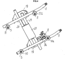
- a rapid inflation device comprises a supply source 2 of pressurised fluid, typically including a compressed air tank fed by a compressor (not shown in the drawings) of any suitable type, and two nozzle holder assemblies 3 and 4, that can be manually moved and controlled by an operator between a rest position and a working position, each nozzle holder assembly comprising one or more blowing-in nozzles 5.
- the inflation device 1 also comprises one or two flexible conduits 6 and 7, designed to put the supply source 2 of pressurised fluid into communication with a respective nozzle holder assembly, 3 and 4 respectively.
- Nozzle holder assemblies 3 and 4 each supports two respective manual controls, e.g.
- shutoff valve 8 and 9 each comprising a respective shutoff valve 8 and 9, that can be operated through a button, 8a and 9a respectively.
- the button is designed to be pressed by an operator's finger, the operator holding nozzle holder assemblies 3 and 4 in his hand.
- a shut-off valve only, e.g. valve 8, as it is sufficient the consent given by one operator's hand.
- each nozzle holder assembly is formed by a rigid collector, such as a pipe part with a blind end.
- the inflation device 1 also comprises safety sensor means, e.g. including four shutoff valves 10, 10a and 11, 11 a, each operated by means of a respective feeler button, designed to rest against the bead of a tyre P to be inflated, which is mounted onto a wheel rim C for detecting whether the respective nozzle holder assembly is in its correct working position.
- safety valve means e.g. comprising an opening-closing valve 13 (normally closed), which is controlled by a check valve 14 connected in series with both shutoff valves 8 and 9 and shutoff valves 10, 10a, 11 and 11a.
- valve 14 will drive valve 13 to open, whereby supplying pressurised fluid from reservoir 2 to blowing-in nozzles 5, only if all shutoff valves 8 and 9 and safety valves 10 and 10a, 11 and 11 a are open.
- tyre P and wheel rim C forming the tyred wheel to be inflated are located over the rotating table 15 of a tyre assembling-disassembling machine 16 provided with a frontal pedestal 17 supporting the rotating table 15, and a rear upright 18, on which nozzle holder assemblies 3 and 4 can be suspended in a rest position.
- reservoir 2 and, preferably, valves 13 and 14 are also supported.
- nozzle holder assemblies 3 and 4 are provided with a suitable handle or grip 19 and slidingly connected to one another, e.g. by way of a respective rod 20 and 21 having a square cross-section, and slidingly mounted in a box-type sleeve 22, so that one nozzle holder assembly can move independently from the other, e.g. to manually adapt itself to different diameters of wheels to be inflated.
- Such an adaptation can preferably occur by drawing in and holding one nozzle holder assembly in position between the edge of the rim C and the bead of the tyre P and extending the other to a position diametrically opposite to the first one, over the tyre P.
- feelers 12 of the safety valves 10, 10a and 11, 11 a can be slidingly arranged along and about (Figs. 1 and 4) the nozzles 5, thereby being activated through the operator's pressing action, only after a respective nozzle being penetrated between rim edge and beam of the tyre P.
- the two nozzle holder assemblies 3 and 4 are connected to one another through two rods 3a and 4a respectively, which rods have one end thereof articulated, respectively at 23 and 24, to the respective nozzle holder assembly 3 and 4, whereas the other end thereof is articulated to a common pin 25.
- Pins 23, 24 and 25 have their axis substantially parallel one to another, whereby the mutual constraint is such to allow one nozzle holder assembly to move near or away from the other.
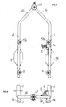
- Figures 7 and 8 show an embodiment in which nozzle holder assemblies 3 and 4 have a respective extension 3b and 4b, that is articulated to the free end thereof about a common pin 26, whereby they can be reciprocally opened wide independently from each other along a common displacement plane.
- the above described rapid inflation device substantially operates as follow.
- the rapid inflation device When not in use, the rapid inflation device can be kept in the rest position hung on a suitable support, such as the rear upright of a tyre assembling-disassembling machine, a wall, or the like. In its rest position, the safety valve is permanently closed and not permit a fluid feeding.
- the opening-closing valve 13 is activated by the non-return valve 14 to generate relatively high pressurised air supply between the beam tyre and the rim for a sudden inflation of the tyre P.
- the above described rapid inflation device therefore prevents the operator from inadvertently or deliberately use the device itself like an air pistol against persons or thinks, which would cause injuries and damages, the same device being capable to supply pressurised air only when resting and being pressed against a wheel to be inflated.
- the operator can proceed to adjust in a simple and quick way the inflating device to different diameters of wheels to be inflated, preferably first placing one tool assembly in the working position and then adjusting the other.
- the inflating device is bounded to the pressurised fluid source 2 by only one or two flexible pipe, the operator has a great working freedom, and can locate the inflating device in a rest position in a comfortable way.
- sensor means 10, 11, 12 can be electrically or electronically operated and electrically connected in series and adapted to send an electric control to an opening/closing valve 13, which in turn comprises a suitable solenoid valve.
- buttons 8a and 9a can be designed to control a respective electric switch connected in series with the sensors 10 and 11.
Landscapes
- Engineering & Computer Science (AREA)
- Mechanical Engineering (AREA)
- Automobile Manufacture Line, Endless Track Vehicle, Trailer (AREA)
- Vehicle Cleaning, Maintenance, Repair, Refitting, And Outriggers (AREA)
Applications Claiming Priority (2)
| Application Number | Priority Date | Filing Date | Title |
|---|---|---|---|
| IT000009A ITVR20040009A1 (it) | 2004-01-23 | 2004-01-23 | Dispositivo di gonfiaggio rapido di un pneumatico senza camera d'aria |
| ITVR20040009 | 2004-01-23 |
Publications (1)
| Publication Number | Publication Date |
|---|---|
| EP1557296A1 true EP1557296A1 (de) | 2005-07-27 |
Family
ID=34631195
Family Applications (1)
| Application Number | Title | Priority Date | Filing Date |
|---|---|---|---|
| EP05001216A Withdrawn EP1557296A1 (de) | 2004-01-23 | 2005-01-21 | Einfüllvorrichtung für schlauchlosen Reifen |
Country Status (5)
| Country | Link |
|---|---|
| US (1) | US7188518B2 (de) |
| EP (1) | EP1557296A1 (de) |
| JP (1) | JP2005206150A (de) |
| CN (1) | CN1651290A (de) |
| IT (1) | ITVR20040009A1 (de) |
Families Citing this family (7)
| Publication number | Priority date | Publication date | Assignee | Title |
|---|---|---|---|---|
| US7311129B1 (en) | 2007-04-10 | 2007-12-25 | William D White | Tire bead seating and inflating apparatus |
| JP4979740B2 (ja) * | 2009-06-17 | 2012-07-18 | 株式会社神戸製鋼所 | タイヤ試験装置の空気圧回路、タイヤ試験装置及びタイヤ試験方法 |
| DE102009046195B3 (de) * | 2009-10-30 | 2011-03-17 | Schenck Rotec Gmbh | Reifenfüllstation und Verfahren zum Füllen von Reifen |
| CN103052515B (zh) * | 2010-04-14 | 2016-09-28 | 盖瑟工具公司 | 无内胎轮胎就座装置 |
| US8448686B2 (en) | 2011-04-07 | 2013-05-28 | Gerald A. Rudebeck | Tire bead setting apparatus and related methods |
| US9834182B2 (en) | 2015-12-08 | 2017-12-05 | Beto Engineering & Marketing Co., Ltd. | Portable tubeless tire inflating device |
| US11807051B1 (en) * | 2023-03-28 | 2023-11-07 | Pro-Tote Systems, Inc. | Tire bead seating device |
Citations (6)
| Publication number | Priority date | Publication date | Assignee | Title |
|---|---|---|---|---|
| US3675705A (en) * | 1970-11-16 | 1972-07-11 | B & J Mfg Co | Tire bead seating and inflation apparatus |
| FR2148197A1 (de) * | 1971-08-02 | 1973-03-11 | Royal Industries | |
| US3736975A (en) * | 1971-09-10 | 1973-06-05 | Coats Co Inc | Tire bead seating and inflating apparatus |
| US3814163A (en) * | 1972-10-18 | 1974-06-04 | B & J Mfg Co | Adjustable bead seater |
| EP1342593A1 (de) * | 2002-03-07 | 2003-09-10 | CORGHI S.p.A. | Vorrichtung zur Wulst-Positionierung und Füllung von Schlauchlosreifen |
| US20030178151A1 (en) * | 2002-01-14 | 2003-09-25 | Ritchie William B. | Cartridge type bead seater apparatus and method of using thereof |
Family Cites Families (1)
| Publication number | Priority date | Publication date | Assignee | Title |
|---|---|---|---|---|
| US6837104B2 (en) * | 2002-10-08 | 2005-01-04 | Itzhak Sapir | Tire safety system |
-
2004
- 2004-01-23 IT IT000009A patent/ITVR20040009A1/it unknown
-
2005
- 2005-01-21 EP EP05001216A patent/EP1557296A1/de not_active Withdrawn
- 2005-01-21 US US11/040,956 patent/US7188518B2/en not_active Expired - Fee Related
- 2005-01-24 CN CNA2005100016091A patent/CN1651290A/zh active Pending
- 2005-01-24 JP JP2005015699A patent/JP2005206150A/ja active Pending
Patent Citations (6)
| Publication number | Priority date | Publication date | Assignee | Title |
|---|---|---|---|---|
| US3675705A (en) * | 1970-11-16 | 1972-07-11 | B & J Mfg Co | Tire bead seating and inflation apparatus |
| FR2148197A1 (de) * | 1971-08-02 | 1973-03-11 | Royal Industries | |
| US3736975A (en) * | 1971-09-10 | 1973-06-05 | Coats Co Inc | Tire bead seating and inflating apparatus |
| US3814163A (en) * | 1972-10-18 | 1974-06-04 | B & J Mfg Co | Adjustable bead seater |
| US20030178151A1 (en) * | 2002-01-14 | 2003-09-25 | Ritchie William B. | Cartridge type bead seater apparatus and method of using thereof |
| EP1342593A1 (de) * | 2002-03-07 | 2003-09-10 | CORGHI S.p.A. | Vorrichtung zur Wulst-Positionierung und Füllung von Schlauchlosreifen |
Also Published As
| Publication number | Publication date |
|---|---|
| US20050229692A1 (en) | 2005-10-20 |
| JP2005206150A (ja) | 2005-08-04 |
| ITVR20040009A1 (it) | 2004-04-23 |
| US7188518B2 (en) | 2007-03-13 |
| CN1651290A (zh) | 2005-08-10 |
Similar Documents
| Publication | Publication Date | Title |
|---|---|---|
| US8910693B2 (en) | Device for demounting a tire from a rim as well as a tire demounting machine equipped with such device | |
| US7343955B2 (en) | Tire changing machine | |
| US9216621B2 (en) | Apparatus for angular positioning of an operating arm of a tire changing machine | |
| EP2231425B1 (de) | Modulare reifenaufblasvorrichtung | |
| CA2591674A1 (en) | A system for transporting and manipulating tires and wheels | |
| US5878801A (en) | Device for sealing a tubeless pneumatic tire to a wheel rim | |
| US7188518B2 (en) | Rapid inflation device for tubeless tire | |
| US4381027A (en) | Tire inflation safety cage | |
| US4263958A (en) | Tire mounting, bead seating and inflation apparatus and method of use | |
| US6761061B2 (en) | Device for tubeless tire bead engagement and inflation | |
| EP3524448B1 (de) | Verfahren zum aufblasen eines reifens | |
| EP3800074B1 (de) | Vorrichtung zur montage eines reifens auf einer felge | |
| US2538962A (en) | Fluid pressure-operated tire bead loosening tool | |
| US6257299B1 (en) | Tyre removal machine with manually or automatically positionable turret | |
| US20240051804A1 (en) | Lifting system | |
| US3736975A (en) | Tire bead seating and inflating apparatus | |
| US3493030A (en) | Tire changing stand with rotatable rim gripping table | |
| US20100166532A1 (en) | Apparatus for manipulating and recovering wheels | |
| US3500892A (en) | Automatic tire-changing machine | |
| US3374819A (en) | Tire removal tool | |
| AU608371B2 (en) | Apparatus for mounting and dismounting of tyres | |
| US3301304A (en) | Device for demounting pneumatic tires from wheel rims therefor | |
| KR200456620Y1 (ko) | 드럼통 리프터 | |
| ITMO20000042A1 (it) | Dispositivo di gonfiaggio per pneumatici senza camera d'aria,cosiddetti tubeless | |
| ITMO20010064A1 (it) | Attrezzo di sostegno per le ruote di motocicli in operazioni di stallonatura dei pneumatici |
Legal Events
| Date | Code | Title | Description |
|---|---|---|---|
| PUAI | Public reference made under article 153(3) epc to a published international application that has entered the european phase |
Free format text: ORIGINAL CODE: 0009012 |
|
| AK | Designated contracting states |
Kind code of ref document: A1 Designated state(s): AT BE BG CH CY CZ DE DK EE ES FI FR GB GR HU IE IS IT LI LT LU MC NL PL PT RO SE SI SK TR |
|
| AX | Request for extension of the european patent |
Extension state: AL BA HR LV MK YU |
|
| AKX | Designation fees paid | ||
| 17P | Request for examination filed |
Effective date: 20060227 |
|
| RBV | Designated contracting states (corrected) |
Designated state(s): AT BE BG CH CY CZ DE DK EE ES FI FR GB GR HU IE IS IT LI LT LU MC NL PL PT RO SE SI SK TR |
|
| REG | Reference to a national code |
Ref country code: DE Ref legal event code: 8566 |
|
| 17Q | First examination report despatched |
Effective date: 20070511 |
|
| GRAP | Despatch of communication of intention to grant a patent |
Free format text: ORIGINAL CODE: EPIDOSNIGR1 |
|
| STAA | Information on the status of an ep patent application or granted ep patent |
Free format text: STATUS: THE APPLICATION IS DEEMED TO BE WITHDRAWN |
|
| 18D | Application deemed to be withdrawn |
Effective date: 20080311 |