EP1556874B1 - Circuit breaker - Google Patents
Circuit breaker Download PDFInfo
- Publication number
- EP1556874B1 EP1556874B1 EP03769653A EP03769653A EP1556874B1 EP 1556874 B1 EP1556874 B1 EP 1556874B1 EP 03769653 A EP03769653 A EP 03769653A EP 03769653 A EP03769653 A EP 03769653A EP 1556874 B1 EP1556874 B1 EP 1556874B1
- Authority
- EP
- European Patent Office
- Prior art keywords
- circuit breaker
- shield
- arc
- electrodes
- circuit
- Prior art date
- Legal status (The legal status is an assumption and is not a legal conclusion. Google has not performed a legal analysis and makes no representation as to the accuracy of the status listed.)
- Expired - Lifetime
Links
- 239000000463 material Substances 0.000 claims abstract description 13
- 230000007246 mechanism Effects 0.000 claims abstract description 7
- 239000007789 gas Substances 0.000 claims description 60
- 238000002679 ablation Methods 0.000 claims description 20
- CURLTUGMZLYLDI-UHFFFAOYSA-N Carbon dioxide Chemical compound O=C=O CURLTUGMZLYLDI-UHFFFAOYSA-N 0.000 claims description 9
- 229920001343 polytetrafluoroethylene Polymers 0.000 claims description 8
- 239000004810 polytetrafluoroethylene Substances 0.000 claims description 8
- 229910002092 carbon dioxide Inorganic materials 0.000 claims description 6
- IJGRMHOSHXDMSA-UHFFFAOYSA-N Atomic nitrogen Chemical compound N#N IJGRMHOSHXDMSA-UHFFFAOYSA-N 0.000 claims description 5
- XKRFYHLGVUSROY-UHFFFAOYSA-N Argon Chemical compound [Ar] XKRFYHLGVUSROY-UHFFFAOYSA-N 0.000 claims description 4
- 238000000034 method Methods 0.000 claims description 4
- 230000008569 process Effects 0.000 claims description 4
- 239000001569 carbon dioxide Substances 0.000 claims description 3
- 239000003570 air Substances 0.000 claims description 2
- 229910052786 argon Inorganic materials 0.000 claims description 2
- 229910052757 nitrogen Inorganic materials 0.000 claims description 2
- 230000009471 action Effects 0.000 abstract description 3
- 238000010891 electric arc Methods 0.000 abstract 1
- SFZCNBIFKDRMGX-UHFFFAOYSA-N sulfur hexafluoride Chemical compound FS(F)(F)(F)(F)F SFZCNBIFKDRMGX-UHFFFAOYSA-N 0.000 description 16
- 230000008033 biological extinction Effects 0.000 description 13
- 230000000694 effects Effects 0.000 description 7
- 238000012360 testing method Methods 0.000 description 5
- 238000002474 experimental method Methods 0.000 description 4
- 238000010304 firing Methods 0.000 description 4
- 229960000909 sulfur hexafluoride Drugs 0.000 description 4
- 239000000872 buffer Substances 0.000 description 3
- 150000002222 fluorine compounds Chemical class 0.000 description 3
- 238000011084 recovery Methods 0.000 description 3
- 230000002829 reductive effect Effects 0.000 description 3
- 239000013626 chemical specie Substances 0.000 description 2
- 230000003628 erosive effect Effects 0.000 description 2
- 239000000835 fiber Substances 0.000 description 2
- 235000019000 fluorine Nutrition 0.000 description 2
- 239000000203 mixture Substances 0.000 description 2
- 230000003389 potentiating effect Effects 0.000 description 2
- 238000011160 research Methods 0.000 description 2
- 230000002441 reversible effect Effects 0.000 description 2
- 230000003068 static effect Effects 0.000 description 2
- 239000000126 substance Substances 0.000 description 2
- TXEYQDLBPFQVAA-UHFFFAOYSA-N tetrafluoromethane Chemical compound FC(F)(F)F TXEYQDLBPFQVAA-UHFFFAOYSA-N 0.000 description 2
- PXGOKWXKJXAPGV-UHFFFAOYSA-N Fluorine Chemical compound FF PXGOKWXKJXAPGV-UHFFFAOYSA-N 0.000 description 1
- 238000013459 approach Methods 0.000 description 1
- 230000008901 benefit Effects 0.000 description 1
- 238000006243 chemical reaction Methods 0.000 description 1
- 230000003247 decreasing effect Effects 0.000 description 1
- 230000001934 delay Effects 0.000 description 1
- 238000013461 design Methods 0.000 description 1
- 238000001514 detection method Methods 0.000 description 1
- 238000010586 diagram Methods 0.000 description 1
- 239000003989 dielectric material Substances 0.000 description 1
- 238000010494 dissociation reaction Methods 0.000 description 1
- 230000005593 dissociations Effects 0.000 description 1
- 239000012777 electrically insulating material Substances 0.000 description 1
- 230000005611 electricity Effects 0.000 description 1
- 230000007613 environmental effect Effects 0.000 description 1
- 238000000605 extraction Methods 0.000 description 1
- 230000002349 favourable effect Effects 0.000 description 1
- 229910052731 fluorine Inorganic materials 0.000 description 1
- 239000011737 fluorine Substances 0.000 description 1
- 125000001153 fluoro group Chemical group F* 0.000 description 1
- 210000004907 gland Anatomy 0.000 description 1
- 239000005431 greenhouse gas Substances 0.000 description 1
- 238000010438 heat treatment Methods 0.000 description 1
- 238000005259 measurement Methods 0.000 description 1
- 239000002184 metal Substances 0.000 description 1
- 239000000178 monomer Substances 0.000 description 1
- 239000005416 organic matter Substances 0.000 description 1
- -1 polytetrafluoroethylene Polymers 0.000 description 1
- 230000006798 recombination Effects 0.000 description 1
- 238000005215 recombination Methods 0.000 description 1
- 230000004044 response Effects 0.000 description 1
- 238000007789 sealing Methods 0.000 description 1
- 239000007787 solid Substances 0.000 description 1
- 238000000859 sublimation Methods 0.000 description 1
- 230000008022 sublimation Effects 0.000 description 1
- 238000005303 weighing Methods 0.000 description 1
- 230000004580 weight loss Effects 0.000 description 1
Images


Classifications
-
- H—ELECTRICITY
- H01—ELECTRIC ELEMENTS
- H01H—ELECTRIC SWITCHES; RELAYS; SELECTORS; EMERGENCY PROTECTIVE DEVICES
- H01H33/00—High-tension or heavy-current switches with arc-extinguishing or arc-preventing means
- H01H33/70—Switches with separate means for directing, obtaining, or increasing flow of arc-extinguishing fluid
- H01H33/76—Switches with separate means for directing, obtaining, or increasing flow of arc-extinguishing fluid wherein arc-extinguishing gas is evolved from stationary parts; Selection of material therefor
- H01H33/78—Switches with separate means for directing, obtaining, or increasing flow of arc-extinguishing fluid wherein arc-extinguishing gas is evolved from stationary parts; Selection of material therefor wherein the break is in gas
-
- H—ELECTRICITY
- H01—ELECTRIC ELEMENTS
- H01H—ELECTRIC SWITCHES; RELAYS; SELECTORS; EMERGENCY PROTECTIVE DEVICES
- H01H33/00—High-tension or heavy-current switches with arc-extinguishing or arc-preventing means
- H01H33/02—Details
- H01H33/53—Cases; Reservoirs, tanks, piping or valves, for arc-extinguishing fluid; Accessories therefor, e.g. safety arrangements, pressure relief devices
- H01H33/56—Gas reservoirs
- H01H2033/566—Avoiding the use of SF6
-
- H—ELECTRICITY
- H01—ELECTRIC ELEMENTS
- H01H—ELECTRIC SWITCHES; RELAYS; SELECTORS; EMERGENCY PROTECTIVE DEVICES
- H01H33/00—High-tension or heavy-current switches with arc-extinguishing or arc-preventing means
- H01H33/70—Switches with separate means for directing, obtaining, or increasing flow of arc-extinguishing fluid
- H01H33/88—Switches with separate means for directing, obtaining, or increasing flow of arc-extinguishing fluid the flow of arc-extinguishing fluid being produced or increased by movement of pistons or other pressure-producing parts
- H01H33/90—Switches with separate means for directing, obtaining, or increasing flow of arc-extinguishing fluid the flow of arc-extinguishing fluid being produced or increased by movement of pistons or other pressure-producing parts this movement being effected by or in conjunction with the contact-operating mechanism
Definitions
- the present invention relates to circuit breakers.
- Circuit breakers typically utilise a pair of electrical contacts, maintained normally in contact with each other, through which an electrical contact is made.
- one contact is moved relative to the other to separate the two contacts.
- an electrical arc is created.
- high voltages are involved it is necessary to arrange for this arc to be extinguished in order to prevent excessive damage to the circuit breaker and other attendant hazards.
- the effect of the gas is further enhanced by arranging, through a "puffer" arrangement of a piston coupled to the circuit breaker's movable electrode, that as the electrodes are separated a flow of gas passes over them.
- US Patent No. 4339641 (General Electric Corporation) discloses such an arrangement.
- the same document illustrates the provision of a shield or nozzle around the electrodes, formed of dielectric material, by means of which the arc is to some degree confined.
- the design of this component is intended among other objects to maximise gas pressure for arc extraction and minimise ablation of the nozzle material.
- Sulphur hexafluoride is recognised as a highly potent greenhouse gas (several orders of magnitude more potent than carbon dioxide) and there are consequently both official recommendations and important commercial incentives to dispense with it.
- One approach which is the subject of currently active research is to seek a substitute dielectric gas. Such research has been based on the use of elevated pressure, as in the known circuit breakers using sulphur hexafluoride.
- An option known in the literature is to use a proportion of sulphur hexafluoride in combination with some other less harmful gas, but clearly the goal of dispensing with SF 6 is not thereby achieved.
- High voltage circuit breakers which do not utilize a dielectric gas for arc extinction but instead have electrodes in an evacuated housing.
- the electrical arc typically generates temperatures sufficient to cause an undesirable degree of ablation of the electrodes themselves, reducing the electrode's working lifetime.
- US Patent 2167665 assigned to the Detroit Edison Company, describes a circuit breaker in which horn fibre or other organic matter is placed adjacent the arc that is decomposed. It also describes an arrangement in which movement of a rod extension, upon opening of the contacts, tends to create decreased pressure which operates to draw the arc through a space between the rod extension and a fibre tube, helping to confine the arc within an arcing space.
- a circuit breaker comprising first and second electrodes which are contactable with each other to complete an electrical circuit, a withdrawal mechanism for moving one electrode away from the other to break the circuit, and a shield arranged in proximity to the electrodes such as to be subject to ablation by the aforementioned arc, the material and arrangement of the shield being such that its ablation by the arc causes it to release arc-extinguishing gas, the device further comprising means for providing, at least in the vicinity of the electrodes and at the instant of striking of an arc between them during breaking of the circuit, a gas pressure below 101325 Pascals, and being characterised by provision of a sealed enclosure containing the electrode and the shield, the enclosure containing a background gas.
- atmospheric pressure in this context is 101325Pa.
- the shield may form a cavity within which the arcing takes place. In this way the desired ablation and also the arc extinguishing effect of the gas can be increased. Pressure within the cavity may be transiently increased by the effects of the arc, further improving arc extinction.
- the shield comprises electrically insulating material.
- Sub-atmospheric pressure in the vicinity of the electrodes may be provided by providing a suitable gas pressure in the enclosure.
- the background gas need not comprise a dielectric gas such as SF 6 .
- SF 6 dielectric gas
- the favoured gas is nitrogen.
- Argon, carbon dioxide and air are potential alternatives.
- the background gas pressure inside the enclosure is 60 kPa or below. 34 kPa (5psi) is believed to be still more favourable. It is currently believed that a pressure above 7 kPa (1psi) is desirable although the effect of pressures below 7 kPa (1 psi) have to date not been thoroughly studied.
- An alternative, or additional, means for providing the required pressure in the vicinity of the electrodes comprises means for withdrawing gas from this vicinity during the .process of breaking the electrical circuit. Pressure is thus transiently reduced in this vicinity.
- a piston/cylinder arrangement may be used to withdraw the gas.
- a circuit breaker embodying the present invention comprises a tubular static electrode 2 coaxially mounted with a cylindrical movable electrode 4.
- the movable electrode 4 is a sliding fit in the fixed electrode 2.
- Fig. 1 shows the movable electrode to be withdrawn from the fixed electrode, in order to break an associated electrical circuit indicated, purely schematically, at 6. However when (as under normal operating conditions) the circuit breaker is closed, the movable electrode contacts the fixed electrode to complete the circuit 6. More specifically, in the present embodiment, an end portion of the movable electrode 4 is received in and contacted by the fixed electrode 2.
- the movable electrode 4 is coupled to a withdrawal mechanism which is schematically indicated at 8.
- Suitable mechanisms are well known in the art, their function being to rapidly withdraw the movable electrode 4 along the direction of the electrode axis, and will not be described in detail herein beyond noting that a standard type of hydraulic actuator may be used, and that pneumatic or solenoid actuated devices are possible alternatives.
- the electrodes are contained in an enclosure 12, formed in the present embodiment as a metal tube.
- the enclosure serves to maintain around the electrodes a background gas, introduced prior to use of the circuit breaker, whose nature and purpose will be considered below.
- the withdrawal mechanism 8 is in this embodiment disposed outside the enclosure 12, the movable electrode 4 emerging from the enclosure through a sealing gland 14 (whereby passage of gas in this region is prevented) to reach the withdrawal mechanism 8.
- an insulating shield 16 is also disposed within the enclosure 12, and in the vicinity of the electrodes 2, 4, disposed within the enclosure 12, and in the vicinity of the electrodes 2, 4, disposed within the enclosure 12, and in the vicinity of the electrodes 2, 4, disposed within the enclosure 12, and in the vicinity of the electrodes 2, 4, disposed within the enclosure 12, and in the vicinity of the electrodes 2, 4, is an insulating shield 16.
- the shield is an annular body into whose interior the movable electrode 4 extends. When the contact breaker is closed, the movable electrode 4 projects out of the shield 16 to contact the static electrode 2.
- the shield lies closely around one of the electrodes, in the present example the movable electrode 2, which it partly surrounds, and is of a type referred to as a "close proximity shield".
- the background gas of the present exemplary embodiment is nitrogen (N 2 ) at a pressure of 25 kPa (3.7 psi). It is found in experiment that the illustrated circuit breaker performs well despite its lack of a background gas (such as SF 6 ) with high dielectric properties, and the fact that the gas is at low pressure. This is contrary to expectation. It is believed by the inventors that this good performance is due to the presence of both the shield and the sub-atmospheric pressure background gas. The inventors have found that in the illustrated circuit breaker ablation promoted arc extinction is enhanced by reducing the background gas pressure below atmospheric pressure.
- a background gas such as SF 6
- the shield comprises a material which ablates to gaseous form in the presence of an electrical arc.
- the PTFE shield is known to be capable of arc induced ablation and to produce in response fluorines and fluorides with excellent arc extinguishing properties. Chemical reactions produce gases including carbon tetrafluoride (CF 4 ) and C 2 F 6 .
- the process involves sublimation of the PTFE monomers and their dissociation, which processes are in themselves endothermic.
- the inventors have calculated, based on the current and duration of the arc and on the mass ablated from the shield, that roughly 30% of the arc's energy can in experimental examples go into ablation of the shield material, assisting extinguishing of the arc.
- the ablated material also provides a "chemical puff" of arc-extinguishing gas. The effect is to provide effective arc extinction without need of SF 6 as a background gas.
- pressure in the region of the electrodes is temporarily increased by the heat and the ablation products generated by the arc and this increased pressure is also believed to assist arc extinction. Products of the ablation may be vented through the open ends of the shield 16.
- Certain of the gases produced by the arc induced shield ablation are in themselves environmentally undesirable but it is believed that at least some of the chemical species produced by arc ablation re-combine to leave materials that are environmentally non-threatening. That is, the chemical species required for arc extinction are, at least in part, only transiently produced. Following arc extinction and with appropriate delays caused by chemical recombination time scales the chemically reactive fluorine/fluorides recombine to form solid fluorides which do not easily disperse to form an environmental threat as do halogenic gases.
- the illustrated embodiment utilises a "reverse puffer" principle. Piston action of the moving contact 4 within the shield 16 is used, upon withdrawal of the contact 4, to reduce the pressure within the cavity in the shield 16. This enables the ablation to be maximised for the thermal recovery (including ablation enhanced pressurisation) whilst subsequently providing sufficient gas pressure for good dielectric withstand.
- Test results are provided in support of the claim regarding the efficacy of sub-atmospheric pressure operation and of gases other than SF 6 .
- Figure 3 shows the shortest gap lengths between contacts required to interrupt an alternating fault current of peak value 20kA for various gas pressure in the range 6kPa to 580 kPa (0.8 to 84 psi), the horizontal scale being logarithmic. Results are provided for five different gases - SF 6 , N 2 , air, CO 2 and Ar. Notable features are:
- Fig. 4 shows the results of experiments to examine the effect of peak alternating current on the critical gap length for current interruption at a pressure of 3.7 psi. These show a trend for the interruption performance at lower currents to be approximately as effective as at 20 KA, as judged by the critical gap length criterion.
- the requirement for sub atmospheric pressure gas in the vicinity of the electrode and shield upon striking of the electrical arc may be met, eg. by virtue of the illustrated "reverse puffer" arrangement, without the ambient pressure of background gas in the enclosure 12 being below atmospheric.
- the background gas pressure may be atmospheric (or conceivably even higher) with the required sub-atmospheric pressure around the electrodes being transiently created when the circuit breaker is activated to break the circuit.
Landscapes
- Circuit Breakers (AREA)
- Valve Device For Special Equipments (AREA)
- Control Of Vending Devices And Auxiliary Devices For Vending Devices (AREA)
- Percussive Tools And Related Accessories (AREA)
- Arc-Extinguishing Devices That Are Switches (AREA)
- Keying Circuit Devices (AREA)
Abstract
Description
- The present invention relates to circuit breakers.
- Circuit breakers typically utilise a pair of electrical contacts, maintained normally in contact with each other, through which an electrical contact is made. In order to break the circuit, eg. upon detection of a fault condition, one contact is moved relative to the other to separate the two contacts. As the contacts are moved apart, due to the potential gradient between them, an electrical arc is created. Where high voltages are involved it is necessary to arrange for this arc to be extinguished in order to prevent excessive damage to the circuit breaker and other attendant hazards.
- It is well known, in order to extinguish the arc, to place the contacts in a sealed vessel filled with a background gas consisting of sulphur hexafluoride (SF6) at high pressure (typically in the region of 600kPa (six atmospheres)). The gas is chosen for its dielectric properties, enhanced by its pressurisation, by virtue of which arcing is reduced. Such circuit breakers are in use in, for example, the substations and switching stations used in commercial electricity supply networks.
- In some examples, the effect of the gas is further enhanced by arranging, through a "puffer" arrangement of a piston coupled to the circuit breaker's movable electrode, that as the electrodes are separated a flow of gas passes over them. US Patent No. 4339641 (General Electric Corporation) discloses such an arrangement.
- The same document illustrates the provision of a shield or nozzle around the electrodes, formed of dielectric material, by means of which the arc is to some degree confined. The design of this component is intended among other objects to maximise gas pressure for arc extraction and minimise ablation of the nozzle material.
- Sulphur hexafluoride is recognised as a highly potent greenhouse gas (several orders of magnitude more potent than carbon dioxide) and there are consequently both official recommendations and important commercial incentives to dispense with it. One approach which is the subject of currently active research is to seek a substitute dielectric gas. Such research has been based on the use of elevated pressure, as in the known circuit breakers using sulphur hexafluoride. An option known in the literature is to use a proportion of sulphur hexafluoride in combination with some other less harmful gas, but clearly the goal of dispensing with SF6 is not thereby achieved.
- High voltage circuit breakers are known which do not utilize a dielectric gas for arc extinction but instead have electrodes in an evacuated housing. However in such devices the electrical arc typically generates temperatures sufficient to cause an undesirable degree of ablation of the electrodes themselves, reducing the electrode's working lifetime.
- An example of a circuit breaker which operates at low pressure is provided by UK patent application 2087651 (Westinghouse Electric Corporation et al). It appears that this is a device having low current density at the contacts and the low gas pressure serves "to minimise contact erosion". Annular shields around the perimeters of the contacts serve to intercept hot, eroded material.
- US Patent 2167665, assigned to the Detroit Edison Company, describes a circuit breaker in which horn fibre or other organic matter is placed adjacent the arc that is decomposed. It also describes an arrangement in which movement of a rod extension, upon opening of the contacts, tends to create decreased pressure which operates to draw the arc through a space between the rod extension and a fibre tube, helping to confine the arc within an arcing space.
- In experiments, the inventors have unexpectedly observed that arc extinction can be enhanced when the pressure of background gas is reduced below atmospheric pressure.
- In accordance with a first aspect of the present invention there is a circuit breaker comprising first and second electrodes which are contactable with each other to complete an electrical circuit, a withdrawal mechanism for moving one electrode away from the other to break the circuit, and a shield arranged in proximity to the electrodes such as to be subject to ablation by the aforementioned arc, the material and arrangement of the shield being such that its ablation by the arc causes it to release arc-extinguishing gas, the device further comprising means for providing, at least in the vicinity of the electrodes and at the instant of striking of an arc between them during breaking of the circuit, a gas pressure below 101325 Pascals, and being characterised by provision of a sealed enclosure containing the electrode and the shield, the enclosure containing a background gas.
- For the avoidance of doubt, atmospheric pressure in this context is 101325Pa.
- It is found by experiment that an effective circuit breaker can be constructed in accordance with the present invention despite, and in fact by virtue of, the low gas pressure utilized. This is contrary to expectation.
- The shield may form a cavity within which the arcing takes place. In this way the desired ablation and also the arc extinguishing effect of the gas can be increased. Pressure within the cavity may be transiently increased by the effects of the arc, further improving arc extinction.
- Preferably the shield comprises electrically insulating material.
- Sub-atmospheric pressure in the vicinity of the electrodes may be provided by providing a suitable gas pressure in the enclosure.
- The background gas need not comprise a dielectric gas such as SF6. Currently the favoured gas is nitrogen. Argon, carbon dioxide and air are potential alternatives.
- It is preferred that the background gas pressure inside the enclosure is 60 kPa or below. 34 kPa (5psi) is believed to be still more favourable. It is currently believed that a pressure above 7 kPa (1psi) is desirable although the effect of pressures below 7 kPa (1 psi) have to date not been thoroughly studied.
- An alternative, or additional, means for providing the required pressure in the vicinity of the electrodes comprises means for withdrawing gas from this vicinity during the .process of breaking the electrical circuit. Pressure is thus transiently reduced in this vicinity. A piston/cylinder arrangement may be used to withdraw the gas.
- A specific embodiment of the present invention will now be described, by way of example only, with reference to the accompanying drawings, in which:-
- Fig. 1 is a somewhat simplified section, in an axial plane, through an embodiment of the present invention;
- Fig. 2 is a simplified section through the same embodiment in a radial plane;
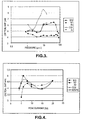
- Fig. 3 is a graph of experimental data, showing the critical electrode gap (vertical axis) against gas pressure (horizontal axis) for several different background gases used in a circuit breaker:
- Fig. 4 is a graph of experimental data, showing critical electrode gap (vertical axis) against peak alternating current (horizontal axis) in a circuit breaker embodying the present invention and using several different background gases; and
- Fig. 5 is a graph of experimental data showing the magnitudes of extinction and re-ignition voltage peaks for different gases, for a gas pressure of 25 kPa (3.7 psi) and peak alternating currents of 20 kA.
- As illustrated in Figs. 1 and 2, a circuit breaker embodying the present invention comprises a tubular
static electrode 2 coaxially mounted with a cylindricalmovable electrode 4. Themovable electrode 4 is a sliding fit in thefixed electrode 2. Fig. 1 shows the movable electrode to be withdrawn from the fixed electrode, in order to break an associated electrical circuit indicated, purely schematically, at 6. However when (as under normal operating conditions) the circuit breaker is closed, the movable electrode contacts the fixed electrode to complete the circuit 6. More specifically, in the present embodiment, an end portion of themovable electrode 4 is received in and contacted by the fixedelectrode 2. - The
movable electrode 4 is coupled to a withdrawal mechanism which is schematically indicated at 8. Suitable mechanisms are well known in the art, their function being to rapidly withdraw themovable electrode 4 along the direction of the electrode axis, and will not be described in detail herein beyond noting that a standard type of hydraulic actuator may be used, and that pneumatic or solenoid actuated devices are possible alternatives. - The electrodes are contained in an
enclosure 12, formed in the present embodiment as a metal tube. The enclosure serves to maintain around the electrodes a background gas, introduced prior to use of the circuit breaker, whose nature and purpose will be considered below. Thewithdrawal mechanism 8 is in this embodiment disposed outside theenclosure 12, themovable electrode 4 emerging from the enclosure through a sealing gland 14 (whereby passage of gas in this region is prevented) to reach thewithdrawal mechanism 8. - Also disposed within the
enclosure 12, and in the vicinity of theelectrodes insulating shield 16. In the present embodiment the shield is an annular body into whose interior themovable electrode 4 extends. When the contact breaker is closed, themovable electrode 4 projects out of theshield 16 to contact thestatic electrode 2. - While other materials may be used, the inventors favour polymeric material for the
insulating shield 16. The currently preferred material is polytetrafluoroethylene (PTFE). The shield lies closely around one of the electrodes, in the present example themovable electrode 2, which it partly surrounds, and is of a type referred to as a "close proximity shield". - The particular arrangement and configuration of the electrodes and shield is presented merely by way of example and may differ in other embodiments.
- The background gas of the present exemplary embodiment is nitrogen (N2) at a pressure of 25 kPa (3.7 psi). It is found in experiment that the illustrated circuit breaker performs well despite its lack of a background gas (such as SF6) with high dielectric properties, and the fact that the gas is at low pressure. This is contrary to expectation. It is believed by the inventors that this good performance is due to the presence of both the shield and the sub-atmospheric pressure background gas. The inventors have found that in the illustrated circuit breaker ablation promoted arc extinction is enhanced by reducing the background gas pressure below atmospheric pressure.
- While the intention is not to limit the present invention by reference to any specific explanation of its performance, it is believed that the effect of the low background gas pressure is to cause the plasma arc produced upon breaking of the circuit to spread more widely, as compared with the arc created in a conventional high pressure device, and thereby to increase ablation of the
shield 16. The shield comprises a material which ablates to gaseous form in the presence of an electrical arc. In the exemplary embodiment the PTFE shield is known to be capable of arc induced ablation and to produce in response fluorines and fluorides with excellent arc extinguishing properties. Chemical reactions produce gases including carbon tetrafluoride (CF4) and C2F6. The process involves sublimation of the PTFE monomers and their dissociation, which processes are in themselves endothermic. The inventors have calculated, based on the current and duration of the arc and on the mass ablated from the shield, that roughly 30% of the arc's energy can in experimental examples go into ablation of the shield material, assisting extinguishing of the arc. The ablated material also provides a "chemical puff" of arc-extinguishing gas. The effect is to provide effective arc extinction without need of SF6 as a background gas. Following striking of the arc, pressure in the region of the electrodes is temporarily increased by the heat and the ablation products generated by the arc and this increased pressure is also believed to assist arc extinction. Products of the ablation may be vented through the open ends of theshield 16. - Certain of the gases produced by the arc induced shield ablation are in themselves environmentally undesirable but it is believed that at least some of the chemical species produced by arc ablation re-combine to leave materials that are environmentally non-threatening. That is, the chemical species required for arc extinction are, at least in part, only transiently produced. Following arc extinction and with appropriate delays caused by chemical recombination time scales the chemically reactive fluorine/fluorides recombine to form solid fluorides which do not easily disperse to form an environmental threat as do halogenic gases.
- In order to enhance dielectric recovery with gas pressure while respecting the need for sub-atmospheric gas pressure for ablation induced arc extinction, the illustrated embodiment utilises a "reverse puffer" principle. Piston action of the moving
contact 4 within theshield 16 is used, upon withdrawal of thecontact 4, to reduce the pressure within the cavity in theshield 16. This enables the ablation to be maximised for the thermal recovery (including ablation enhanced pressurisation) whilst subsequently providing sufficient gas pressure for good dielectric withstand. - Test results are provided in support of the claim regarding the efficacy of sub-atmospheric pressure operation and of gases other than SF6. Figure 3 shows the shortest gap lengths between contacts required to interrupt an alternating fault current of peak value 20kA for various gas pressure in the range 6kPa to 580 kPa (0.8 to 84 psi), the horizontal scale being logarithmic. Results are provided for five different gases - SF6, N2, air, CO2 and Ar. Notable features are:
- (a) Relatively small dependence upon gas pressure with SF6
- (b) The improved interruption with N2 for p<48kPa (7psi)
- (c) The similar performance of N2 to SF6 for p<48kPa (7psi)
- (d) The similar behaviour of CO2, air to N2, SF6 for p<48kPa (7psi)
- (e) The generally poorer performance of Ar but nonetheless showing a similar trend as N2 and CO2.
- The similar performance of the gases tested below 48kPa (7psi) implies the dominance of a common feature believed to be ablation of the shield and pressurisation due to arc heating of the products of ablation.
- Weighing the PTFE shield used in the tests after some 250 test firings indicates on average a PTFE weight loss of 0.14 grams per firing (for cylinder and moving electrode diameter 2.2cm). The erosion of the PTFE wall was significant but not excessive and performance deteriorated only slightly over 250 tests at fault currents of 20KA max.
- Fig. 4 shows the results of experiments to examine the effect of peak alternating current on the critical gap length for current interruption at a pressure of 3.7 psi. These show a trend for the interruption performance at lower currents to be approximately as effective as at 20 KA, as judged by the critical gap length criterion.
- Tests have also been conducted on an 80:20 N2:SF6 mixture, which behaves in a similar manner to pure SF6 and N2. At the present state of knowledge, there therefore appears to be no significant advantage in utilising N2:SF6 mixtures in preference to pure N2 unless the recovery of dielectric strength might be improved.
- The critical gap length results of Figs. 3 and 4 are supported by measurements of the magnitude of the voltage extinction peaks close to the critical gap length for current interruption for the various gases at 20kA peak current and a pressure of 25kPa (3.7 psi), Fig. 5. In this diagram the labels on the Z axis are as follows:-
- XP1 = first half-cycle extinction peak;
- XP2 = second half-cycle extinction peak;
- RP = second half-cycle re-ignition peak;
- (1) denotes 1 x half cycle critical firing and
- (2) denotes 2 x half cycle pre-critical firing.
- It should be noted that the requirement for sub atmospheric pressure gas in the vicinity of the electrode and shield upon striking of the electrical arc may be met, eg. by virtue of the illustrated "reverse puffer" arrangement, without the ambient pressure of background gas in the
enclosure 12 being below atmospheric. Thus the background gas pressure may be atmospheric (or conceivably even higher) with the required sub-atmospheric pressure around the electrodes being transiently created when the circuit breaker is activated to break the circuit. - Furthermore the pressure in this vicinity is, as has been noted above, increased by the action of the electrical arc and so is transiently increased following striking of the arc.
Claims (11)
- A circuit breaker comprising first and second electrodes (2, 4) which are contactable with each other to complete an electrical circuit (6), a withdrawal mechanism (8) for moving one electrode away from the other to break the circuit, and a shield (12) arranged in proximity to the electrodes such as to be subject to ablation by the aforementioned arc, the material and arrangement of the shield being such that its ablation by the arc causes it to release arc-extinguishing gas, the device further comprising means (4, 8, 16) for providing, at least in the vicinity of the electrodes and at the instant of striking of an arc between them during breaking of the circuit, a gas pressure below 101325 Pascals, and being characterised by provision of a sealed enclosure containing the electrode and the shield, the enclosure containing a background gas.
- A circuit breaker as claimed in claim 1 wherein the shield (12) defines a cavity within which arcing takes place.
- A circuit breaker as claimed in claim 1 or claim 2 wherein the shield (12) comprises polymeric material.
- A circuit breaker as claimed in any preceding claim wherein the shield (12) comprises PTFE.
- A circuit breaker as claimed in any preceding claim comprising means (4, 8,16) for withdrawing gas from the vicinity of the first and second electrodes (2, 4) during the process of breaking the electric circuit (6), thereby transiently reducing pressure in this vicinity.
- A circuit breaker as claimed in claim 5, wherein the aforesaid means for withdrawing gas comprises a piston/cylinder arrangement (4, 16).
- A circuit breaker as claimed in claim 6, wherein the piston is formed by one of the first and second electrodes (2, 4).
- A circuit breaker as claimed in claim 6 or claim 7, wherein the cylinder is formed by the shield (16).
- A circuit breaker as claimed in any preceding claim, wherein the background gas pressure is sub-atmospheric.
- A circuit breaker as claimed in any preceding claim, wherein the background gas comprises at least one of nitrogen, argon, carbon dioxide and air.
- A circuit breaker as claimed in any preceding claim, wherein the background gas is at a pressure of 60 kPa or less.
Applications Claiming Priority (3)
| Application Number | Priority Date | Filing Date | Title |
|---|---|---|---|
| GBGB0225088.4A GB0225088D0 (en) | 2002-10-29 | 2002-10-29 | circuit breaker |
| GB0225088 | 2002-10-29 | ||
| PCT/GB2003/004617 WO2004040610A1 (en) | 2002-10-29 | 2003-10-28 | Circuit breaker |
Publications (2)
| Publication Number | Publication Date |
|---|---|
| EP1556874A1 EP1556874A1 (en) | 2005-07-27 |
| EP1556874B1 true EP1556874B1 (en) | 2007-03-28 |
Family
ID=9946740
Family Applications (1)
| Application Number | Title | Priority Date | Filing Date |
|---|---|---|---|
| EP03769653A Expired - Lifetime EP1556874B1 (en) | 2002-10-29 | 2003-10-28 | Circuit breaker |
Country Status (8)
| Country | Link |
|---|---|
| US (1) | US20050247676A1 (en) |
| EP (1) | EP1556874B1 (en) |
| JP (1) | JP2006505108A (en) |
| AT (1) | ATE358327T1 (en) |
| AU (1) | AU2003278343A1 (en) |
| DE (1) | DE60312882T2 (en) |
| GB (1) | GB0225088D0 (en) |
| WO (1) | WO2004040610A1 (en) |
Families Citing this family (2)
| Publication number | Priority date | Publication date | Assignee | Title |
|---|---|---|---|---|
| US20120326323A1 (en) * | 2010-02-09 | 2012-12-27 | Microsemi Corporation | High voltage high package pressure semiconductor package |
| FR2985081B1 (en) * | 2011-12-21 | 2015-03-06 | Alstom Technology Ltd | DEVICE FOR PROTECTION AGAINST PARTICLES GENERATED BY AN ELECTRIC SWITCHING ARC |
Family Cites Families (10)
| Publication number | Priority date | Publication date | Assignee | Title |
|---|---|---|---|---|
| US2167665A (en) * | 1934-11-05 | 1939-08-01 | Detroit Edison Co | Circuit breaker |
| US2156974A (en) * | 1935-06-12 | 1939-05-02 | Gilbert E Doan | Method of and apparatus for nonarcing circuit interruption |
| US3446927A (en) * | 1966-01-10 | 1969-05-27 | Wagner Electric Corp | Disk contacts and flat annular shield arrangement in gas filled switch |
| US3781500A (en) * | 1972-10-02 | 1973-12-25 | Westinghouse Electric Corp | Gas cooled electrical contactor |
| DD108407A1 (en) * | 1973-12-20 | 1974-09-12 | ||
| US4426560A (en) * | 1980-11-13 | 1984-01-17 | Westinghouse Electric Corp. | Reduced pressure electrical switch |
| JPH09231885A (en) * | 1996-02-22 | 1997-09-05 | Hitachi Ltd | Gas circuit breaker |
| US6236010B1 (en) * | 1999-07-14 | 2001-05-22 | Southern States, Inc. | Circuit interrupter including a penetrating electrical contact with grip and release structure |
| FR2809531B1 (en) * | 2000-05-25 | 2002-07-05 | Alstom | INSULATING BLOWER NOZZLE FOR CIRCUIT BREAKER |
| FR2811137B1 (en) * | 2000-07-03 | 2002-08-23 | Alstom | MANEUVERING ROD FOR HIGH VOLTAGE CIRCUIT BREAKER |
-
2002
- 2002-10-29 GB GBGB0225088.4A patent/GB0225088D0/en not_active Ceased
-
2003
- 2003-10-28 AT AT03769653T patent/ATE358327T1/en not_active IP Right Cessation
- 2003-10-28 WO PCT/GB2003/004617 patent/WO2004040610A1/en not_active Ceased
- 2003-10-28 DE DE60312882T patent/DE60312882T2/en not_active Expired - Lifetime
- 2003-10-28 EP EP03769653A patent/EP1556874B1/en not_active Expired - Lifetime
- 2003-10-28 JP JP2004547769A patent/JP2006505108A/en active Pending
- 2003-10-28 AU AU2003278343A patent/AU2003278343A1/en not_active Abandoned
-
2005
- 2005-04-28 US US11/119,051 patent/US20050247676A1/en not_active Abandoned
Also Published As
| Publication number | Publication date |
|---|---|
| AU2003278343A1 (en) | 2004-05-25 |
| GB0225088D0 (en) | 2002-12-04 |
| US20050247676A1 (en) | 2005-11-10 |
| ATE358327T1 (en) | 2007-04-15 |
| DE60312882D1 (en) | 2007-05-10 |
| EP1556874A1 (en) | 2005-07-27 |
| WO2004040610A1 (en) | 2004-05-13 |
| JP2006505108A (en) | 2006-02-09 |
| DE60312882T2 (en) | 2008-01-31 |
Similar Documents
| Publication | Publication Date | Title |
|---|---|---|
| JP5127569B2 (en) | Gas insulated switch | |
| CN101047077B (en) | Gas insulated switch | |
| US11699559B2 (en) | Device for interrupting non-short circuit currents only, in particular disconnector or earthing switch | |
| US20120228264A1 (en) | Use of specific composite materials as electric arc extinction materials in electrical equipment | |
| US6107590A (en) | Circuit-breaker with an explosive charge ignited during opening operation | |
| EP3477675B1 (en) | Gas-insulated medium-voltage switch with shield device | |
| CN104054151A (en) | Gas circuit breaker | |
| US4110580A (en) | Gas-type circuit-interrupters having admixtures of helium with small concentrations of sulfur-hexafluoride (SF6) gas | |
| JP2004164994A (en) | Switch | |
| CN110556265A (en) | A Rotary Contact Structure Suitable for Capacitive Load Switching Vacuum Interrupter | |
| US20050247676A1 (en) | Circuit breaker | |
| RU2094886C1 (en) | Arc-control device of gas-filled autocompression high-voltage circuit breaker | |
| EP4141901B1 (en) | Metal enclosed circuit breaker | |
| JP2563855B2 (en) | High voltage circuit breaker | |
| KR100345691B1 (en) | Hybrid-extinction type gas circuit breaker | |
| JP2012054097A (en) | Gas-blast circuit breaker | |
| EP4117006B1 (en) | Gas-insulated high or medium voltage circuit breaker | |
| JP7539363B2 (en) | Power Switchgear | |
| Kristoffersen et al. | Puffer-type load break switch for medium voltage gas insulated switchgear filled with dry air | |
| EP3826042B1 (en) | Arcing contact tulip with flow optimized slits and integrated stress relief feature | |
| Telfer et al. | A Novel Approach to Power Circuit Breaker Design for Replacement of SF6 | |
| JP2000166034A (en) | Gas insulated switchgear | |
| JP2002298711A (en) | Gas circuit breaker | |
| Armstrong et al. | Vaccum techniques in modern circuit breakers | |
| JP2001286017A (en) | Switchgear |
Legal Events
| Date | Code | Title | Description |
|---|---|---|---|
| PUAI | Public reference made under article 153(3) epc to a published international application that has entered the european phase |
Free format text: ORIGINAL CODE: 0009012 |
|
| 17P | Request for examination filed |
Effective date: 20050426 |
|
| AK | Designated contracting states |
Kind code of ref document: A1 Designated state(s): AT BE BG CH CY CZ DE DK EE ES FI FR GB GR HU IE IT LI LU MC NL PT RO SE SI SK TR |
|
| AX | Request for extension of the european patent |
Extension state: AL LT LV MK |
|
| DAX | Request for extension of the european patent (deleted) | ||
| 17Q | First examination report despatched |
Effective date: 20060307 |
|
| GRAP | Despatch of communication of intention to grant a patent |
Free format text: ORIGINAL CODE: EPIDOSNIGR1 |
|
| GRAS | Grant fee paid |
Free format text: ORIGINAL CODE: EPIDOSNIGR3 |
|
| GRAA | (expected) grant |
Free format text: ORIGINAL CODE: 0009210 |
|
| AK | Designated contracting states |
Kind code of ref document: B1 Designated state(s): AT BE BG CH CY CZ DE DK EE ES FI FR GB GR HU IE IT LI LU MC NL PT RO SE SI SK TR |
|
| PG25 | Lapsed in a contracting state [announced via postgrant information from national office to epo] |
Ref country code: BE Free format text: LAPSE BECAUSE OF FAILURE TO SUBMIT A TRANSLATION OF THE DESCRIPTION OR TO PAY THE FEE WITHIN THE PRESCRIBED TIME-LIMIT Effective date: 20070328 Ref country code: SI Free format text: LAPSE BECAUSE OF FAILURE TO SUBMIT A TRANSLATION OF THE DESCRIPTION OR TO PAY THE FEE WITHIN THE PRESCRIBED TIME-LIMIT Effective date: 20070328 Ref country code: FI Free format text: LAPSE BECAUSE OF FAILURE TO SUBMIT A TRANSLATION OF THE DESCRIPTION OR TO PAY THE FEE WITHIN THE PRESCRIBED TIME-LIMIT Effective date: 20070328 Ref country code: AT Free format text: LAPSE BECAUSE OF FAILURE TO SUBMIT A TRANSLATION OF THE DESCRIPTION OR TO PAY THE FEE WITHIN THE PRESCRIBED TIME-LIMIT Effective date: 20070328 Ref country code: LI Free format text: LAPSE BECAUSE OF FAILURE TO SUBMIT A TRANSLATION OF THE DESCRIPTION OR TO PAY THE FEE WITHIN THE PRESCRIBED TIME-LIMIT Effective date: 20070328 Ref country code: CH Free format text: LAPSE BECAUSE OF FAILURE TO SUBMIT A TRANSLATION OF THE DESCRIPTION OR TO PAY THE FEE WITHIN THE PRESCRIBED TIME-LIMIT Effective date: 20070328 Ref country code: NL Free format text: LAPSE BECAUSE OF FAILURE TO SUBMIT A TRANSLATION OF THE DESCRIPTION OR TO PAY THE FEE WITHIN THE PRESCRIBED TIME-LIMIT Effective date: 20070328 |
|
| REG | Reference to a national code |
Ref country code: GB Ref legal event code: FG4D |
|
| REG | Reference to a national code |
Ref country code: CH Ref legal event code: EP |
|
| REF | Corresponds to: |
Ref document number: 60312882 Country of ref document: DE Date of ref document: 20070510 Kind code of ref document: P |
|
| REG | Reference to a national code |
Ref country code: IE Ref legal event code: FG4D |
|
| PG25 | Lapsed in a contracting state [announced via postgrant information from national office to epo] |
Ref country code: SE Free format text: LAPSE BECAUSE OF FAILURE TO SUBMIT A TRANSLATION OF THE DESCRIPTION OR TO PAY THE FEE WITHIN THE PRESCRIBED TIME-LIMIT Effective date: 20070628 |
|
| PG25 | Lapsed in a contracting state [announced via postgrant information from national office to epo] |
Ref country code: ES Free format text: LAPSE BECAUSE OF FAILURE TO SUBMIT A TRANSLATION OF THE DESCRIPTION OR TO PAY THE FEE WITHIN THE PRESCRIBED TIME-LIMIT Effective date: 20070709 |
|
| PG25 | Lapsed in a contracting state [announced via postgrant information from national office to epo] |
Ref country code: PT Free format text: LAPSE BECAUSE OF FAILURE TO SUBMIT A TRANSLATION OF THE DESCRIPTION OR TO PAY THE FEE WITHIN THE PRESCRIBED TIME-LIMIT Effective date: 20070828 |
|
| REG | Reference to a national code |
Ref country code: CH Ref legal event code: PL |
|
| NLV1 | Nl: lapsed or annulled due to failure to fulfill the requirements of art. 29p and 29m of the patents act | ||
| EN | Fr: translation not filed | ||
| PG25 | Lapsed in a contracting state [announced via postgrant information from national office to epo] |
Ref country code: SK Free format text: LAPSE BECAUSE OF FAILURE TO SUBMIT A TRANSLATION OF THE DESCRIPTION OR TO PAY THE FEE WITHIN THE PRESCRIBED TIME-LIMIT Effective date: 20070328 |
|
| PG25 | Lapsed in a contracting state [announced via postgrant information from national office to epo] |
Ref country code: RO Free format text: LAPSE BECAUSE OF FAILURE TO SUBMIT A TRANSLATION OF THE DESCRIPTION OR TO PAY THE FEE WITHIN THE PRESCRIBED TIME-LIMIT Effective date: 20070328 Ref country code: CZ Free format text: LAPSE BECAUSE OF FAILURE TO SUBMIT A TRANSLATION OF THE DESCRIPTION OR TO PAY THE FEE WITHIN THE PRESCRIBED TIME-LIMIT Effective date: 20070328 |
|
| PG25 | Lapsed in a contracting state [announced via postgrant information from national office to epo] |
Ref country code: DK Free format text: LAPSE BECAUSE OF FAILURE TO SUBMIT A TRANSLATION OF THE DESCRIPTION OR TO PAY THE FEE WITHIN THE PRESCRIBED TIME-LIMIT Effective date: 20070328 |
|
| PLBE | No opposition filed within time limit |
Free format text: ORIGINAL CODE: 0009261 |
|
| STAA | Information on the status of an ep patent application or granted ep patent |
Free format text: STATUS: NO OPPOSITION FILED WITHIN TIME LIMIT |
|
| 26N | No opposition filed |
Effective date: 20080102 |
|
| PG25 | Lapsed in a contracting state [announced via postgrant information from national office to epo] |
Ref country code: FR Free format text: LAPSE BECAUSE OF FAILURE TO SUBMIT A TRANSLATION OF THE DESCRIPTION OR TO PAY THE FEE WITHIN THE PRESCRIBED TIME-LIMIT Effective date: 20071116 Ref country code: IT Free format text: LAPSE BECAUSE OF FAILURE TO SUBMIT A TRANSLATION OF THE DESCRIPTION OR TO PAY THE FEE WITHIN THE PRESCRIBED TIME-LIMIT Effective date: 20070328 Ref country code: GR Free format text: LAPSE BECAUSE OF FAILURE TO SUBMIT A TRANSLATION OF THE DESCRIPTION OR TO PAY THE FEE WITHIN THE PRESCRIBED TIME-LIMIT Effective date: 20070629 |
|
| PG25 | Lapsed in a contracting state [announced via postgrant information from national office to epo] |
Ref country code: MC Free format text: LAPSE BECAUSE OF NON-PAYMENT OF DUE FEES Effective date: 20071031 |
|
| PG25 | Lapsed in a contracting state [announced via postgrant information from national office to epo] |
Ref country code: IE Free format text: LAPSE BECAUSE OF NON-PAYMENT OF DUE FEES Effective date: 20071030 |
|
| PG25 | Lapsed in a contracting state [announced via postgrant information from national office to epo] |
Ref country code: FR Free format text: LAPSE BECAUSE OF FAILURE TO SUBMIT A TRANSLATION OF THE DESCRIPTION OR TO PAY THE FEE WITHIN THE PRESCRIBED TIME-LIMIT Effective date: 20070328 |
|
| PG25 | Lapsed in a contracting state [announced via postgrant information from national office to epo] |
Ref country code: EE Free format text: LAPSE BECAUSE OF FAILURE TO SUBMIT A TRANSLATION OF THE DESCRIPTION OR TO PAY THE FEE WITHIN THE PRESCRIBED TIME-LIMIT Effective date: 20070328 |
|
| PG25 | Lapsed in a contracting state [announced via postgrant information from national office to epo] |
Ref country code: CY Free format text: LAPSE BECAUSE OF FAILURE TO SUBMIT A TRANSLATION OF THE DESCRIPTION OR TO PAY THE FEE WITHIN THE PRESCRIBED TIME-LIMIT Effective date: 20070328 |
|
| PG25 | Lapsed in a contracting state [announced via postgrant information from national office to epo] |
Ref country code: BG Free format text: LAPSE BECAUSE OF FAILURE TO SUBMIT A TRANSLATION OF THE DESCRIPTION OR TO PAY THE FEE WITHIN THE PRESCRIBED TIME-LIMIT Effective date: 20070628 Ref country code: LU Free format text: LAPSE BECAUSE OF NON-PAYMENT OF DUE FEES Effective date: 20071028 |
|
| PG25 | Lapsed in a contracting state [announced via postgrant information from national office to epo] |
Ref country code: HU Free format text: LAPSE BECAUSE OF FAILURE TO SUBMIT A TRANSLATION OF THE DESCRIPTION OR TO PAY THE FEE WITHIN THE PRESCRIBED TIME-LIMIT Effective date: 20070929 Ref country code: TR Free format text: LAPSE BECAUSE OF FAILURE TO SUBMIT A TRANSLATION OF THE DESCRIPTION OR TO PAY THE FEE WITHIN THE PRESCRIBED TIME-LIMIT Effective date: 20070328 |
|
| PGFP | Annual fee paid to national office [announced via postgrant information from national office to epo] |
Ref country code: DE Payment date: 20121025 Year of fee payment: 10 |
|
| PGFP | Annual fee paid to national office [announced via postgrant information from national office to epo] |
Ref country code: GB Payment date: 20121024 Year of fee payment: 10 |
|
| GBPC | Gb: european patent ceased through non-payment of renewal fee |
Effective date: 20131028 |
|
| PG25 | Lapsed in a contracting state [announced via postgrant information from national office to epo] |
Ref country code: GB Free format text: LAPSE BECAUSE OF NON-PAYMENT OF DUE FEES Effective date: 20131028 |
|
| REG | Reference to a national code |
Ref country code: DE Ref legal event code: R119 Ref document number: 60312882 Country of ref document: DE Effective date: 20140501 |
|
| PG25 | Lapsed in a contracting state [announced via postgrant information from national office to epo] |
Ref country code: DE Free format text: LAPSE BECAUSE OF NON-PAYMENT OF DUE FEES Effective date: 20140501 |