EP1555858A2 - Zentrale Spannungsversorgung von Betriebsgeräten für Leuchtmittel, eine zentralePFC-Korrektureinheit aufweisend - Google Patents
Zentrale Spannungsversorgung von Betriebsgeräten für Leuchtmittel, eine zentralePFC-Korrektureinheit aufweisend Download PDFInfo
- Publication number
- EP1555858A2 EP1555858A2 EP04028277A EP04028277A EP1555858A2 EP 1555858 A2 EP1555858 A2 EP 1555858A2 EP 04028277 A EP04028277 A EP 04028277A EP 04028277 A EP04028277 A EP 04028277A EP 1555858 A2 EP1555858 A2 EP 1555858A2
- Authority
- EP
- European Patent Office
- Prior art keywords
- output circuit
- central
- rectifier unit
- voltage
- central rectifier
- Prior art date
- Legal status (The legal status is an assumption and is not a legal conclusion. Google has not performed a legal analysis and makes no representation as to the accuracy of the status listed.)
- Granted
Links
- 238000000034 method Methods 0.000 claims abstract description 20
- 238000012544 monitoring process Methods 0.000 claims description 13
- 238000012937 correction Methods 0.000 claims description 6
- 230000001105 regulatory effect Effects 0.000 abstract description 4
- 238000002565 electrocardiography Methods 0.000 description 7
- 238000012545 processing Methods 0.000 description 7
- 230000005540 biological transmission Effects 0.000 description 3
- 230000006978 adaptation Effects 0.000 description 2
- 238000013461 design Methods 0.000 description 2
- 238000010586 diagram Methods 0.000 description 2
- 230000007175 bidirectional communication Effects 0.000 description 1
- 230000002457 bidirectional effect Effects 0.000 description 1
- 230000015572 biosynthetic process Effects 0.000 description 1
- 239000003990 capacitor Substances 0.000 description 1
- 230000001276 controlling effect Effects 0.000 description 1
- 230000001419 dependent effect Effects 0.000 description 1
- 239000003792 electrolyte Substances 0.000 description 1
- 238000004519 manufacturing process Methods 0.000 description 1
- 230000003071 parasitic effect Effects 0.000 description 1
- 230000008054 signal transmission Effects 0.000 description 1
- 230000001960 triggered effect Effects 0.000 description 1
Images

Classifications
-
- H—ELECTRICITY
- H05—ELECTRIC TECHNIQUES NOT OTHERWISE PROVIDED FOR
- H05B—ELECTRIC HEATING; ELECTRIC LIGHT SOURCES NOT OTHERWISE PROVIDED FOR; CIRCUIT ARRANGEMENTS FOR ELECTRIC LIGHT SOURCES, IN GENERAL
- H05B41/00—Circuit arrangements or apparatus for igniting or operating discharge lamps
- H05B41/14—Circuit arrangements
- H05B41/26—Circuit arrangements in which the lamp is fed by power derived from DC by means of a converter, e.g. by high-voltage DC
- H05B41/28—Circuit arrangements in which the lamp is fed by power derived from DC by means of a converter, e.g. by high-voltage DC using static converters
- H05B41/282—Circuit arrangements in which the lamp is fed by power derived from DC by means of a converter, e.g. by high-voltage DC using static converters with semiconductor devices
- H05B41/285—Arrangements for protecting lamps or circuits against abnormal operating conditions
- H05B41/2851—Arrangements for protecting lamps or circuits against abnormal operating conditions for protecting the circuit against abnormal operating conditions
-
- H—ELECTRICITY
- H05—ELECTRIC TECHNIQUES NOT OTHERWISE PROVIDED FOR
- H05B—ELECTRIC HEATING; ELECTRIC LIGHT SOURCES NOT OTHERWISE PROVIDED FOR; CIRCUIT ARRANGEMENTS FOR ELECTRIC LIGHT SOURCES, IN GENERAL
- H05B41/00—Circuit arrangements or apparatus for igniting or operating discharge lamps
- H05B41/14—Circuit arrangements
- H05B41/24—Circuit arrangements in which the lamp is fed by high frequency AC, or with separate oscillator frequency
- H05B41/245—Circuit arrangements in which the lamp is fed by high frequency AC, or with separate oscillator frequency for a plurality of lamps
-
- H—ELECTRICITY
- H05—ELECTRIC TECHNIQUES NOT OTHERWISE PROVIDED FOR
- H05B—ELECTRIC HEATING; ELECTRIC LIGHT SOURCES NOT OTHERWISE PROVIDED FOR; CIRCUIT ARRANGEMENTS FOR ELECTRIC LIGHT SOURCES, IN GENERAL
- H05B41/00—Circuit arrangements or apparatus for igniting or operating discharge lamps
- H05B41/14—Circuit arrangements
- H05B41/26—Circuit arrangements in which the lamp is fed by power derived from DC by means of a converter, e.g. by high-voltage DC
- H05B41/28—Circuit arrangements in which the lamp is fed by power derived from DC by means of a converter, e.g. by high-voltage DC using static converters
- H05B41/295—Circuit arrangements in which the lamp is fed by power derived from DC by means of a converter, e.g. by high-voltage DC using static converters with semiconductor devices and specially adapted for lamps with preheating electrodes, e.g. for fluorescent lamps
- H05B41/298—Arrangements for protecting lamps or circuits against abnormal operating conditions
- H05B41/2981—Arrangements for protecting lamps or circuits against abnormal operating conditions for protecting the circuit against abnormal operating conditions
Definitions
- the present invention relates to the control of Lamp operating devices starting from a central Unit.
- the invention proceeds from a in Fig. 2 schematically shown system.
- this is Illuminant a gas discharge lamp 5, by a Electric ballast (ECG) 1 as operating device is controlled.
- ECG Electric ballast
- this electronic ballast 1 has a Rectifier with power factor correction circuit (PFC, Power Factor Correction) 2, an electrolyte storage capacitor 4 and an RF inverter 3, the again by means of its output circuit 6 the Gas discharge lamp 5 drives.
- the DC voltage Bus voltage
- an emergency lighting controller 7 may be provided be.
- the rectifier 2 in the ECG 1 is usually with AC voltage 9, for example, mains voltage supplied.
- ECG 1 via a digital or To control analog bus control 8, thus the lamp 5 to start, dim or turn off.
- ECG 1 lamp operating device
- PFC circuit Such a PFC circuit is known to reduce disturbing harmonics in the input current.
- ECG 1 inverter with PFC 2 represents a significant cost factor, which is the trend towards Extremely cost-effectively manufactured electronic ballasts strongly limited.
- the central point of the invention is that the unit Rectifier / PFC no longer local in each control gear, but is provided centrally for several operating devices.
- a System for the central power supply of operating devices (Resources) provided for lighting The system points while a central rectifier unit with a input side connection for AC voltage and at least a DC output circuit. Furthermore, several Operating equipment for illuminants provided, each over the DC output circuit are supplied with voltage. It points the central rectifier unit a circuit for regulation voltage, current and / or power Output circuit on.
- the central rectifier unit for example a circuit for limiting the current of the DC output circuit exhibit.
- the central rectifier unit can be designed to switch off the DC output circuit as soon as the (monitored) Voltage of the DC output circuit a predetermined value below.
- the central rectifier unit a Monitoring unit for the state of the DC output circuit exhibit.
- the monitoring unit can predefined changes of the State of the DC output circuit as faults of connected control gear for lamps and / or as Evaluate defined feedback signals of a control gear.
- the central rectifier unit can be a signal interface have information about her in advance future load changes, in particular load jumps in the DC output circuit can be fed.
- the central rectifier unit for example, in the form be built parallel modules, depending on the information regarding future load changes modules be switched on or off.
- the central rectifier unit can control the DC output circuit in a standby state in which the bus voltage is reduced.
- the reduced bus voltage advantageously be chosen such that they are used to power logic components, such as Asics, in a control gear for Illuminant is sufficient.
- the central rectifier unit can continue have a power factor correction unit.
- According to another aspect of the present invention is a Method for the central power supply of operating devices intended for bulbs. It regulates a central Rectifier unit the voltage, the current and / or the Power in a DC output circuit.
- a method for central power supply of Operating devices for lighting provided, with a central rectifier unit in advance information about future load changes, in particular load jumps in the DC output circuit be fed so that the central Rectifier unit in advance on such expected Can adjust load changes.
- a central processing unit is included for example, a rectifier 2 and possibly also a Power factor correction circuit (PFC) 10, common to several light-emitting devices 1, 1 ', 1 "provided Central unit 2 is supplied with (mains) AC voltage 9.
- the central unit 2, 10 can also spatially from the Be separate from control gear and, for example, centrally for a room, a floor or even a building in a control cabinet etc. to be ordered.
- the bulbs themselves can be operated with DC or AC voltage, where in last case in the associated operating device Inverter is provided.
- a DC output circuit 11 of Central unit also other (eg passive) lighting or building services, such as a Light sensor 5 "or a motion detector (not shown) be connected.
- other lighting or building services such as a Light sensor 5 "or a motion detector (not shown) be connected.
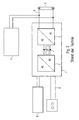
- a DC output circuit 11, 12th As shown schematically in Fig. 1 can be a Output circuit 11 be configured bus-like, so that starting from this central common bus 11 the various Operating devices 1, 1 ', 1 "via stubs 13, 13', 13" be supplied.
- Operating devices individual output circuits 12 may be provided.
- This DC output circuit has the advantage of being compared less vulnerable to corresponding AC circuits parasitic effects.
- the Central unit provided for several operating devices together is, wherein the central unit with the operating devices means connected to at least one DC output circuit.
- At least one PFC 10 can be an example.
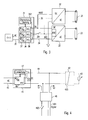
- FIG. 3 is a central control unit 31 shown having a plurality of rectifier / PFC modules 36, which are arranged parallel to each other. Furthermore, in the central rectifier unit 31 a monitoring / control unit 393 provided.
- Comparable to the embodiment of Fig. 1 is the central rectifier unit 31 an AC voltage 35, in particular fed to a mains voltage.
- the rectifier unit 31 has in the embodiment of Fig. 3, a plurality of DC output circuits on, namely a high-voltage output circuit 39, a low-voltage output circuit 392 and a non-voltage-carrying Terminal 34, which is connected to ground.
- About the mentioned DC output circuits 39, 392 and 34 are connected operating devices 32 for lamps 33 supplied.
- FIG. 3 are schematic electronic ballasts (ECGs) with inverters DC / AC provided with which gas discharge lamps 33 in in itself can be controlled known manner.
- ECGs electronic ballasts
- the low-voltage output circuit 302 also for signal transmission (for example in the form of a digital bus) from the central unit 31 to the connected operating devices 32 and possibly vice versa (bidirectional bus).
- the central rectifier unit 31 at least with respect to the DC output circuit 39, so a pure power-supplying DC output circuit without control function, the Voltage U, the current I and / or the power P by means of Monitoring / control circuit 393 monitored.
- the monitoring / control circuit 31 can perform the function have a current limit of the DC output circuit 39. It should be noted that, in certain cases, the Low-voltage output circuit 392 for power supply can serve. This is for example advantageously in the Control of LEDs the case. In this case, the Monitoring / control function of voltage, current and / or the power also on these output circuits application Find.
- the monitoring / control unit 393 may have a function have that the DC output circuit is turned off, if the voltage of the corresponding DC output circuit one predetermined value falls below.
- the Central unit 31 for example, a DC output circuit (for example, 39) in a standby state in which the bus voltage is lowered significantly.
- a DC output circuit for example, 39
- the lowered bus voltage can be chosen such that they still supply power to logic components (For example, Asics) in a connected operating device suffice.
- a connected operating device 32 in be put in a standby state in which the control logic is still actively supplied with power, the current bus voltage but not for controlling, for example, a connected Gas discharge lamp 33 would suffice.
- the lowering of the bus voltage on the other hand has the advantage that in the event that starting from a high bus voltage of For example, 400 volts in the DC output circuit 39 a Low-voltage supply voltage of, for example, 12 volts for Logic components is obtained in the generation of the Low-voltage power supply occurring (ohmic) losses be significantly reduced.
- FIG. 4 a particular be explained advantageous procedure as he with the present invention is achievable.
- the Central processing unit 41 with only one rectifier / power factor correction module 46 it should be understood that also here the parallel modular structure as known from Fig. 3, Can be used.
- the current, the voltage and / or the power of DC output circuit 44 for connected equipment 42 for connected bulbs 43 monitored and regulated.
- the invention will be sudden load changes, in particular load jumps in the DC output circuit 44, i. the corresponding state change of the resources 42 with connected bulbs 43, only executed if in advance an information (S1 in FIG. 4) to the central processing unit 41 was transmitted.
- parameters of the central processing unit 41 be set so that this on the expected future load in the DC output circuit 44 sets.
- These Setting may be in the transmission of the embodiment of Fig. 3 on the sequence of FIG. 4 are that connected in parallel in the central unit 41 be switched off.
- the values can also for the regulated parameter power, current or voltage in advance in expectation of a power leap in the DC output circuit be set.
- Fig. 4 are drive signals for changing the state of a luminous means 43, for example from a digital or analog bus 491 or from a Pushbutton or switch command 492 of a powerline modulation unit 48 transmitted.
- This modulation unit 48 thus modulates control signals to the DC output circuit 44.
- the connected equipment 42 is a powerline demodulator 493 on to 44 transmitted commands over the bus to be able to read.
- a power change for a lighting means 43 means the switch or button 492 and / or via the digital or
- the powerline modulator 48 generates from this a Vorabnachricht to the central unit 41, so these by reading the powerline message from the DC output circuit 44 detected. Then the parameter adaptation takes place in the Central processing unit 41. Finally, the central processing unit 41 confirms opposite the powerline modulator 48 that the adaptation was executed. Only then does the powerline modulator transmit 48 the actual control command in a step S3 on the DC bus 44 or a separate control line to be controlled Operating resources 42.
Landscapes
- Circuit Arrangement For Electric Light Sources In General (AREA)
- Dc-Dc Converters (AREA)
- Rectifiers (AREA)
- Circuit Arrangements For Discharge Lamps (AREA)
Abstract
Description
- Fig. 1
- zeigt eine schematische Ansicht eines erfindungsgemäßen Steuersystems für Leuchtmittel-Betriebsgeräte mit zentraler Gleichrichter/PFC-Einheit und DC-Ausgangskreis,
- Fig. 2
- zeigt eine aus dem Stand der Technik bekannte Betriebsmittel-Ausgestaltung für Gasentladungslampen,
- Fig. 3
- zeigt einen ersten schematischen Schaltplan eines Ausführungsbeispiels der vorliegenden Erfindung, und
- Fig. 4
- zeigt einen schematischen Schaltplan zur Erläuterung des Ablaufs bei einer Vorab-Informationen einer zentralen Gleichrichter-Einheit bezüglich zukünftiger zu erwartender Lastsprünge im DC-Ausgangskreis.
Claims (28)
- System zur zentralen Spannungsversorgung von Betriebsgeräten für Leuchtmittel, aufweisend:wobei die zentrale Gleichrichter-Einheit (31) eine Schaltung (393, 36) zur Regelung der Spannung, des Stroms und/oder der Leistung des Ausgangskreises aufweist.eine zentrale Gleichrichter-Einheit (31) mit einem eingangsseitigen Anschluss für Wechselspannung (35) und wenigstens einem DC-Ausgangskreis (39, 392), undmehreren Betriebsgeräten (32) für Leuchtmittel (33), die über den DC-Ausgangskreis (39, 392) mit Spannung versorgt sind,
- System nach Anspruch 1,
dadurch gekennzeichnet, dass die zentrale Gleichrichter-Einheit (31) eine Schaltung (393, 36) zur Strombegrenzung des DC-Ausgangskreises aufweist. - System nach Anspruch 1 oder 2,
dadurch gekennzeichnet, dass die zentrale Gleichrichter-Einheit (31) dazu ausgelegt ist, den DC-Ausgangskreis (39, 392) abzuschalten, falls die Spannung des DC-Ausgangskreis einen vorbestimmten Wert unterschreitet. - System nach einem der vorhergehenden Ansprüche,
dadurch gekennzeichnet, dass die zentrale Gleichrichter-Einheit (31) eine Überwachungseinheit (393) aufweist, die den Zustand des DC-Ausgangskreis auswertet. - System nach Anspruch 4,
dadurch gekennzeichnet, dass die Überwachungseinheit (393) vorab definierte Änderungen des Zustands des DC-Ausgangskreises (39, 392) als Störungen der angeschlossenen Betriebsgeräte (32) für Leuchtmittel (33) wertet und ein Störsignal erzeugt. - System nach Anspruch 4,
dadurch gekennzeichnet, dass die Überwachungseinheit (393) vorab definierte Änderungen des Zustands des DC-Ausgangskreises als definierte Rückmeldung eines Betriebsgeräts (32) für Leuchtmittel (33) über den DC-Ausgangskreis auswertet. - System nach einem der vorhergehenden Ansprüche,
dadurch gekennzeichnet, dass die zentrale Gleichrichtereinheit (31) eine Signal-Schnittstelle aufweist, über die ihr vorab Informationen über zukünftige Laständerungen, insbesondere.Lastsprünge im DC-Ausgangskreis (39, 393) zuführbar sind. - System nach Anspruch 7,
dadurch gekennzeichnet, dass abhängig von den Informationen bzgl. zukünftiger Laständerungen Parameter der zentralen Gleichrichtereinheit (31) einstellbar sind. - System nach Anspruch 8,
dadurch gekennzeichnet, dass die zentrale Gleichrichtereinheit (31) in Form parallel geschalteter Module (36) aufgebaut ist, wobei abhängig von den Informationen bzgl. zukünftiger Laständerungen Module zu- bzw. abgeschaltbar sind. - System nach einem der vorhergehenden Anprüche,
dadurch gekennzeichnet, dass die zentrale Gleichrichtereinheit (31) den DC-Ausgangskreis in einen Standby-Zustand mit verringerter Busspannung überführen kann. - System nach Anspruch 10,
dadurch gekennzeichnet, dass die verringerte Busspanung derart gewählt ist, dass sie zur Versorgung von Logikbauteilen in einem Betriebsgerät (32) für Leuchtmittel (33) ausreicht. - System nach einem der vorhergehenden Ansprüche,
dadurch gekennzeichnet, dass die zentrale Gleichrichtereinheit weiterhin eine Leistungsfaktor-Korrektureinheit aufweist. - System nach einem der vorhergehenden Ansprüche,
dadurch gekennzeichnet, dass die zentrale Steuereinheit (31) mehrere parallel geschaltete Gleichrichter/PFC-Module (36) aufweist. - Verfahren zur zentralen Spannungsversorgung von Betriebsgeräten für Leuchtmittel, wobei:einer zentrale Gleichrichter-Einheit (31) an einem eingangsseitigen Anschluss Wechselspannung zugeführt wird, die gleichgerichtet und an wenigstens einem DC-Ausgangskreis (39, 392) bereitgestellt wird, undmehrere Betriebsgeräte (32) für Leuchtmittel (33) über den DC-Ausgangskreis mit Spannung versorgt werden, unddie zentrale Gleichrichter-Einheit (31) die Spannung, den Strom und/oder die Leistung des Ausgangskreises regelt.
- Verfahren nach Anspruch 14,
dadurch gekennzeichnet, dass die zentrale Gleichrichter-Einheit (31) den Strom des DC-Ausgangskreises begrenzt. - Verfahren nach Anspruch 14 oder 15,
dadurch gekennzeichnet, dass die zentrale Gleichrichter-Einheit (31) den DC-Ausgangskreis (39, 392) abschaltet, falls die Spannung des DC-Ausgangskreis einen vorbestimmten Wert unterschreitet. - Verfahren nach einem der Ansprüche 14 bis 16,
dadurch gekennzeichnet, dass die zentrale Gleichrichter-Einheit (31) den Zustand des DC-Ausgangskreis überwacht und auswertet. - Verfahren nach Anspruch 17,
dadurch gekennzeichnet, dass die Überwachungseinheit (393) vorab definierte Änderungen des Zustands des DC-Ausgangskreises als Störungen der angeschlossenen Betriebsgeräte 32 für Leuchtmittel (33) wertet und ein Störsignal erzeugt. - Verfahren nach Anspruch 18,
dadurch gekennzeichnet, dass die Überwachungseinheit (393) vorab definierte Änderungen des Zustands des DC-Ausgangskreises als definierte Rückmeldung eines Betriebsgeräts (32) für Leuchtmittel (33) über den DC-Ausgangskreis auswertet. - Verfahren nach einem der Ansprüche 14 bis 19,
dadurch gekennzeichnet, dass der zentralen Gleichrichtereinheit (31) vorab Informationen über zukünftige Laständerungen, insbesondere Lastsprünge im DC-Ausgangskreis zugeführt werden. - Verfahren nach Anspruch 20,
dadurch gekennzeichnet, dass abhängig von den Informationen bzgl. zukünftiger Laständerungen Parameter der zentralen Gleichrichtereinheit (31) eingestellt werden. - Verfahren nach Anspruch 21,
dadurch gekennzeichnet, dass die Laständerungen erst nach erfolgter Einstellung der Parameter der zentralen Gleichrichtereinheit ausgeführt werden. - Verfahren nach Anspruch 22,
dadurch gekennzeichnet, dass eine Steuereinheit (48) zuerst die Einstellung der Parameter der zentralen Gleichrichtereinheit (31) veranlasst, bevor laständernde Stellwert-Signale an ein Betriebgerät für Leuchtmittel übersandt werden. - Verfahren nach einem der Ansprüche 21 bis 23,
dadurch gekennzeichnet, dass die zentrale Gleichrichtereinheit (31) in Form parallel geschalteter Module (36) aufgebaut ist, wobei abhängig von den Informationen bzgl. zukünftiger Laständerungen Module zu- bzw. abgeschaltet werden. - Verfahren nach einem der Anprüche 14 bis 24,
dadurch gekennzeichnet, dass in einem Standby-Zustand die Spannung des DC-Ausgangskreises abgesenkt wird. - Verfahren nach Anspruch 25,
dadurch gekennzeichnet, dass die verringerte Busspanung derart gewählt ist, dass sie zur Versorgung von Logikbauteilen in einem Betriebsgerät für Leichtmittel ausreicht. - Verfahren zur zentralen Spannungsversorgung von Betriebsgeräten für Leuchtmittel, wobei:eine zentrale Gleichrichtereinheit (31) an einem eingangsseitigen Anschluss Wechselspannung (45) zugeführt wird, die gleichgerichtet (46) und an wenigstens einem DC-Ausgangskreis (44) bereitgestellt wird, undmehrere Betriebsgeräte (42) für Leuchtmittel (43) über den DC-Ausgangskreis (44) mit Spannung versorgt werden, undder zentralen Gleichrichtereinheit (41) vorab Informationen über zukünftige Laständerungen (S1), insbesondere Lastsprünge im DC-Ausgangskreis (44) zugeführt werden.
- Computersoftware-Produkt,
dadurch gekennzeichnet, dass es ein Verfahren nach einem der Ansprüche 14 bis 27 unterstützt, wenn es in einer Recheneinrichtung läuft, die Teil eines Beleuchtungs-Steuersystems ist.
Priority Applications (2)
| Application Number | Priority Date | Filing Date | Title |
|---|---|---|---|
| EP11162425.0A EP2365737B1 (de) | 2004-01-14 | 2004-11-29 | Zentraler PFC mit DC-Ausgangskreisregelung |
| PL04028277T PL1555858T3 (pl) | 2004-01-14 | 2004-11-29 | Centralne zasilanie dla urządzeń obsługujących źródła światła, zawierające centralną jednostkę PFC |
Applications Claiming Priority (2)
| Application Number | Priority Date | Filing Date | Title |
|---|---|---|---|
| DE102004002027.2A DE102004002027B4 (de) | 2004-01-14 | 2004-01-14 | Zentraler PFC mit DC-Ausgangskreisregelung |
| DE102004002027 | 2004-01-14 |
Related Child Applications (2)
| Application Number | Title | Priority Date | Filing Date |
|---|---|---|---|
| EP11162425.0A Division EP2365737B1 (de) | 2004-01-14 | 2004-11-29 | Zentraler PFC mit DC-Ausgangskreisregelung |
| EP11162425.0 Division-Into | 2011-04-14 |
Publications (3)
| Publication Number | Publication Date |
|---|---|
| EP1555858A2 true EP1555858A2 (de) | 2005-07-20 |
| EP1555858A3 EP1555858A3 (de) | 2005-08-31 |
| EP1555858B1 EP1555858B1 (de) | 2011-08-17 |
Family
ID=34609553
Family Applications (2)
| Application Number | Title | Priority Date | Filing Date |
|---|---|---|---|
| EP04028277A Expired - Lifetime EP1555858B1 (de) | 2004-01-14 | 2004-11-29 | Zentrale Spannungsversorgung von Betriebsgeräten für Leuchtmittel, eine zentralePFC-Korrektureinheit aufweisend |
| EP11162425.0A Expired - Lifetime EP2365737B1 (de) | 2004-01-14 | 2004-11-29 | Zentraler PFC mit DC-Ausgangskreisregelung |
Family Applications After (1)
| Application Number | Title | Priority Date | Filing Date |
|---|---|---|---|
| EP11162425.0A Expired - Lifetime EP2365737B1 (de) | 2004-01-14 | 2004-11-29 | Zentraler PFC mit DC-Ausgangskreisregelung |
Country Status (4)
| Country | Link |
|---|---|
| EP (2) | EP1555858B1 (de) |
| AT (1) | ATE521214T1 (de) |
| DE (1) | DE102004002027B4 (de) |
| PL (1) | PL1555858T3 (de) |
Cited By (3)
| Publication number | Priority date | Publication date | Assignee | Title |
|---|---|---|---|---|
| WO2014176612A1 (de) * | 2013-04-30 | 2014-11-06 | Tridonic Gmbh & Co. Kg | Effektbeleuchtung |
| AT14100U1 (de) * | 2013-10-16 | 2015-04-15 | Tridonic Gmbh & Co Kg | Verfahren und Vorrichtungen zur Kommunikation in einem Beleuchtungssystem |
| CN104955219A (zh) * | 2014-03-25 | 2015-09-30 | 赤多尼科两合股份有限公司 | 照明系统和使用用于信息发送的功耗操控照明系统的方法 |
Families Citing this family (3)
| Publication number | Priority date | Publication date | Assignee | Title |
|---|---|---|---|---|
| EP3058794B1 (de) | 2013-10-15 | 2018-08-29 | Philips Lighting Holding B.V. | Ansteuerungsschaltung und verfahren zur steuerung eines beleuchtungselements |
| DE102015005240A1 (de) * | 2015-04-26 | 2016-10-27 | Tilman Röder | Verfahren zur Installation eines Stromverteilungssystems im Bereich von Kleinspannung unter 25 Volt AC oder 60 Volt DC, bei dem mindestens ein Netzteil für die Versorgung von zwei oder mehr möglichen Stromverbrauchern verwendetwird und ein entsprechendes Stromverteilungssystem sowie zugehörige Vorrichtung |
| DE102015117206A1 (de) * | 2015-10-08 | 2017-04-13 | I.S.T. Innovative Sewer Technologies Gmbh | Aushärtevorrichtung mit einer UV-Licht erzeugenden Lampe |
Citations (6)
| Publication number | Priority date | Publication date | Assignee | Title |
|---|---|---|---|---|
| EP0411618A2 (de) | 1989-08-04 | 1991-02-06 | Zumtobel Aktiengesellschaft | Elektronisches Vorschaltgerät für Gasentladungslampen |
| WO1994027419A1 (en) | 1993-05-13 | 1994-11-24 | Etta Industries, Inc. | System and method for distributing power to gas discharge lamps |
| WO2000072435A1 (en) | 1999-05-24 | 2000-11-30 | Semiconductor Components Industries, L.L.C. | Protecting switching power supply from fault condition |
| EP1231821A1 (de) | 2001-02-09 | 2002-08-14 | Patent-Treuhand-Gesellschaft für elektrische Glühlampen mbH | Vorschaltgerät zum Betrieb von elektrischen Lampen |
| EP1244337A1 (de) | 2001-03-20 | 2002-09-25 | MAGNETEK S.p.A. | Beleuchtungsanordnung mit Stromleiterschiene und mehreren Beleuchtungskörpern |
| US6534933B2 (en) | 2001-05-15 | 2003-03-18 | Koninklijke Philips Electronics N.V. | High power factor electronic ballast with load dependent bus voltage regulation |
Family Cites Families (6)
| Publication number | Priority date | Publication date | Assignee | Title |
|---|---|---|---|---|
| US5367229A (en) * | 1991-03-28 | 1994-11-22 | Yang Thien S | Lamp ballasts |
| DE19502772C2 (de) * | 1995-01-30 | 2002-02-28 | Walter Holzer | Elektronisches Vorschaltgerät für Leuchtstofflampen |
| EP0903966B1 (de) * | 1997-09-18 | 2003-04-16 | CEAG Sicherheitstechnik GmbH | Beleuchtungssystem |
| EP1771048A3 (de) * | 2000-09-15 | 2007-04-11 | TridonicAtco GmbH & Co. KG | Elektronisches Vorschaltgerät mit digitaler Steuereinheit |
| IT1316561B1 (it) * | 2000-12-28 | 2003-04-22 | Setech S R L | Dispositivo di alimentazione di lampade a sarica a catodo freddo. |
| US6621238B2 (en) * | 2002-01-25 | 2003-09-16 | General Electric Company | Power factor correction circuit with faster bus charging rate during startup |
-
2004
- 2004-01-14 DE DE102004002027.2A patent/DE102004002027B4/de not_active Expired - Fee Related
- 2004-11-29 AT AT04028277T patent/ATE521214T1/de active
- 2004-11-29 PL PL04028277T patent/PL1555858T3/pl unknown
- 2004-11-29 EP EP04028277A patent/EP1555858B1/de not_active Expired - Lifetime
- 2004-11-29 EP EP11162425.0A patent/EP2365737B1/de not_active Expired - Lifetime
Patent Citations (6)
| Publication number | Priority date | Publication date | Assignee | Title |
|---|---|---|---|---|
| EP0411618A2 (de) | 1989-08-04 | 1991-02-06 | Zumtobel Aktiengesellschaft | Elektronisches Vorschaltgerät für Gasentladungslampen |
| WO1994027419A1 (en) | 1993-05-13 | 1994-11-24 | Etta Industries, Inc. | System and method for distributing power to gas discharge lamps |
| WO2000072435A1 (en) | 1999-05-24 | 2000-11-30 | Semiconductor Components Industries, L.L.C. | Protecting switching power supply from fault condition |
| EP1231821A1 (de) | 2001-02-09 | 2002-08-14 | Patent-Treuhand-Gesellschaft für elektrische Glühlampen mbH | Vorschaltgerät zum Betrieb von elektrischen Lampen |
| EP1244337A1 (de) | 2001-03-20 | 2002-09-25 | MAGNETEK S.p.A. | Beleuchtungsanordnung mit Stromleiterschiene und mehreren Beleuchtungskörpern |
| US6534933B2 (en) | 2001-05-15 | 2003-03-18 | Koninklijke Philips Electronics N.V. | High power factor electronic ballast with load dependent bus voltage regulation |
Cited By (6)
| Publication number | Priority date | Publication date | Assignee | Title |
|---|---|---|---|---|
| WO2014176612A1 (de) * | 2013-04-30 | 2014-11-06 | Tridonic Gmbh & Co. Kg | Effektbeleuchtung |
| AT14100U1 (de) * | 2013-10-16 | 2015-04-15 | Tridonic Gmbh & Co Kg | Verfahren und Vorrichtungen zur Kommunikation in einem Beleuchtungssystem |
| CN104955219A (zh) * | 2014-03-25 | 2015-09-30 | 赤多尼科两合股份有限公司 | 照明系统和使用用于信息发送的功耗操控照明系统的方法 |
| EP2925094A1 (de) * | 2014-03-25 | 2015-09-30 | Tridonic GmbH & Co KG | Beleuchtungssystem und Verfahren zum Betreiben eines Beleuchtungssystems mit Verwendung des Stromverbrauchs zur Informationsübertragung |
| US9468077B2 (en) | 2014-03-25 | 2016-10-11 | Tridonic Gmbh & Co Kg | Lighting system and method for operating a lighting system using power consumption for information transmission |
| CN104955219B (zh) * | 2014-03-25 | 2019-03-08 | 赤多尼科两合股份有限公司 | 照明系统和用于操控照明系统的方法 |
Also Published As
| Publication number | Publication date |
|---|---|
| ATE521214T1 (de) | 2011-09-15 |
| EP2365737A3 (de) | 2013-12-11 |
| EP1555858A3 (de) | 2005-08-31 |
| EP2365737A2 (de) | 2011-09-14 |
| DE102004002027B4 (de) | 2020-03-26 |
| PL1555858T3 (pl) | 2012-01-31 |
| EP2365737B1 (de) | 2019-01-30 |
| EP1555858B1 (de) | 2011-08-17 |
| DE102004002027A1 (de) | 2005-08-04 |
Similar Documents
| Publication | Publication Date | Title |
|---|---|---|
| EP1555859B1 (de) | Ansteuerung von Leuchtmittel-Betriebsgeräten über einen modulierten DC-Bus | |
| EP2353345B1 (de) | Adaptiver pfc für leuchtmittel-lastkreis, insbesondere lastkreis mit led | |
| EP2604097B1 (de) | Modulation eines pfc bei dc-betrieb | |
| EP1947913B1 (de) | DC-versorgte Betriebsmittel-Module für Leuchtmittel | |
| DE102005018775A1 (de) | Parametrisierbarer digitaler PFC | |
| EP1555861B1 (de) | Steuerung von Betriebsgeräten für Leuchtmittel mittels Schaltmodulation eines DC-Busses | |
| EP2365737B1 (de) | Zentraler PFC mit DC-Ausgangskreisregelung | |
| EP2278861B1 (de) | Zentrale Versorgung über mehrere DC-Ausgangskreise | |
| EP1271745B1 (de) | Verfahren zum Betrieb elektrischer Endverbraucher sowie eine Einrichtung zur Durchführung des Verfahrens | |
| EP1583402B1 (de) | Ansteuerung von Leuchtmittel-Betriebsgeräten mit einem zentralen kaskadierten AC/DC-Konverter | |
| DE112011102274B4 (de) | Steuerung von Betriebsparametern von Betriebsgeräten für LED | |
| WO2011041817A2 (de) | Verfahren zur ansteuerung von leuchtmittelbetriebsgeräten | |
| WO2014172734A1 (de) | Betriebsschaltung für leds | |
| WO2011106814A2 (de) | Betriebsgerät für leuchtmittel | |
| DE102004012216B4 (de) | Ansteuerung von Leuchtmittel-Betriebsgeräten über einen schaltbaren DC-Bus | |
| DE102006001256A1 (de) | Verfahren zum Betreiben einer Lichtquelle mit Hilfe eines Lampenbetriebsgeräts sowie Lampenbetriebsgerät hierfür | |
| DE102008035219A1 (de) | Steuerschaltung zur Steuerung einer Lampenbetriebsschaltung für Leuchtmittel | |
| WO2006114176A1 (de) | Einstellbare digitale leuchtmittelleistungsregelung |
Legal Events
| Date | Code | Title | Description |
|---|---|---|---|
| PUAI | Public reference made under article 153(3) epc to a published international application that has entered the european phase |
Free format text: ORIGINAL CODE: 0009012 |
|
| PUAL | Search report despatched |
Free format text: ORIGINAL CODE: 0009013 |
|
| AK | Designated contracting states |
Kind code of ref document: A2 Designated state(s): AT BE BG CH CY CZ DE DK EE ES FI FR GB GR HU IE IS IT LI LU MC NL PL PT RO SE SI SK TR |
|
| AX | Request for extension of the european patent |
Extension state: AL HR LT LV MK YU |
|
| AK | Designated contracting states |
Kind code of ref document: A3 Designated state(s): AT BE BG CH CY CZ DE DK EE ES FI FR GB GR HU IE IS IT LI LU MC NL PL PT RO SE SI SK TR |
|
| AX | Request for extension of the european patent |
Extension state: AL HR LT LV MK YU |
|
| 17P | Request for examination filed |
Effective date: 20051010 |
|
| AKX | Designation fees paid |
Designated state(s): AT BE BG CH CY CZ DE DK EE ES FI FR GB GR HU IE IS IT LI LU MC NL PL PT RO SE SI SK TR |
|
| 17Q | First examination report despatched |
Effective date: 20090415 |
|
| RAP1 | Party data changed (applicant data changed or rights of an application transferred) |
Owner name: TRIDONIC GMBH & CO KG |
|
| GRAP | Despatch of communication of intention to grant a patent |
Free format text: ORIGINAL CODE: EPIDOSNIGR1 |
|
| GRAS | Grant fee paid |
Free format text: ORIGINAL CODE: EPIDOSNIGR3 |
|
| GRAA | (expected) grant |
Free format text: ORIGINAL CODE: 0009210 |
|
| AK | Designated contracting states |
Kind code of ref document: B1 Designated state(s): AT BE BG CH CY CZ DE DK EE ES FI FR GB GR HU IE IS IT LI LU MC NL PL PT RO SE SI SK TR |
|
| REG | Reference to a national code |
Ref country code: GB Ref legal event code: FG4D Free format text: NOT ENGLISH |
|
| REG | Reference to a national code |
Ref country code: CH Ref legal event code: EP |
|
| REG | Reference to a national code |
Ref country code: IE Ref legal event code: FG4D Free format text: LANGUAGE OF EP DOCUMENT: GERMAN |
|
| REG | Reference to a national code |
Ref country code: DE Ref legal event code: R096 Ref document number: 502004012795 Country of ref document: DE Effective date: 20111013 |
|
| REG | Reference to a national code |
Ref country code: NL Ref legal event code: VDEP Effective date: 20110817 |
|
| PG25 | Lapsed in a contracting state [announced via postgrant information from national office to epo] |
Ref country code: SE Free format text: LAPSE BECAUSE OF FAILURE TO SUBMIT A TRANSLATION OF THE DESCRIPTION OR TO PAY THE FEE WITHIN THE PRESCRIBED TIME-LIMIT Effective date: 20110817 Ref country code: NL Free format text: LAPSE BECAUSE OF FAILURE TO SUBMIT A TRANSLATION OF THE DESCRIPTION OR TO PAY THE FEE WITHIN THE PRESCRIBED TIME-LIMIT Effective date: 20110817 Ref country code: PT Free format text: LAPSE BECAUSE OF FAILURE TO SUBMIT A TRANSLATION OF THE DESCRIPTION OR TO PAY THE FEE WITHIN THE PRESCRIBED TIME-LIMIT Effective date: 20111219 Ref country code: FI Free format text: LAPSE BECAUSE OF FAILURE TO SUBMIT A TRANSLATION OF THE DESCRIPTION OR TO PAY THE FEE WITHIN THE PRESCRIBED TIME-LIMIT Effective date: 20110817 Ref country code: IS Free format text: LAPSE BECAUSE OF FAILURE TO SUBMIT A TRANSLATION OF THE DESCRIPTION OR TO PAY THE FEE WITHIN THE PRESCRIBED TIME-LIMIT Effective date: 20111217 |
|
| REG | Reference to a national code |
Ref country code: PL Ref legal event code: T3 |
|
| PG25 | Lapsed in a contracting state [announced via postgrant information from national office to epo] |
Ref country code: CY Free format text: LAPSE BECAUSE OF FAILURE TO SUBMIT A TRANSLATION OF THE DESCRIPTION OR TO PAY THE FEE WITHIN THE PRESCRIBED TIME-LIMIT Effective date: 20110817 Ref country code: GR Free format text: LAPSE BECAUSE OF FAILURE TO SUBMIT A TRANSLATION OF THE DESCRIPTION OR TO PAY THE FEE WITHIN THE PRESCRIBED TIME-LIMIT Effective date: 20111118 Ref country code: SI Free format text: LAPSE BECAUSE OF FAILURE TO SUBMIT A TRANSLATION OF THE DESCRIPTION OR TO PAY THE FEE WITHIN THE PRESCRIBED TIME-LIMIT Effective date: 20110817 |
|
| REG | Reference to a national code |
Ref country code: IE Ref legal event code: FD4D |
|
| REG | Reference to a national code |
Ref country code: HU Ref legal event code: AG4A Ref document number: E012405 Country of ref document: HU |
|
| PG25 | Lapsed in a contracting state [announced via postgrant information from national office to epo] |
Ref country code: SK Free format text: LAPSE BECAUSE OF FAILURE TO SUBMIT A TRANSLATION OF THE DESCRIPTION OR TO PAY THE FEE WITHIN THE PRESCRIBED TIME-LIMIT Effective date: 20110817 Ref country code: IE Free format text: LAPSE BECAUSE OF FAILURE TO SUBMIT A TRANSLATION OF THE DESCRIPTION OR TO PAY THE FEE WITHIN THE PRESCRIBED TIME-LIMIT Effective date: 20110817 Ref country code: CZ Free format text: LAPSE BECAUSE OF FAILURE TO SUBMIT A TRANSLATION OF THE DESCRIPTION OR TO PAY THE FEE WITHIN THE PRESCRIBED TIME-LIMIT Effective date: 20110817 |
|
| BERE | Be: lapsed |
Owner name: TRIDONIC GMBH & CO KG Effective date: 20111130 |
|
| PG25 | Lapsed in a contracting state [announced via postgrant information from national office to epo] |
Ref country code: RO Free format text: LAPSE BECAUSE OF FAILURE TO SUBMIT A TRANSLATION OF THE DESCRIPTION OR TO PAY THE FEE WITHIN THE PRESCRIBED TIME-LIMIT Effective date: 20110817 Ref country code: EE Free format text: LAPSE BECAUSE OF FAILURE TO SUBMIT A TRANSLATION OF THE DESCRIPTION OR TO PAY THE FEE WITHIN THE PRESCRIBED TIME-LIMIT Effective date: 20110817 |
|
| PLBE | No opposition filed within time limit |
Free format text: ORIGINAL CODE: 0009261 |
|
| STAA | Information on the status of an ep patent application or granted ep patent |
Free format text: STATUS: NO OPPOSITION FILED WITHIN TIME LIMIT |
|
| PG25 | Lapsed in a contracting state [announced via postgrant information from national office to epo] |
Ref country code: MC Free format text: LAPSE BECAUSE OF NON-PAYMENT OF DUE FEES Effective date: 20111130 Ref country code: DK Free format text: LAPSE BECAUSE OF FAILURE TO SUBMIT A TRANSLATION OF THE DESCRIPTION OR TO PAY THE FEE WITHIN THE PRESCRIBED TIME-LIMIT Effective date: 20110817 |
|
| REG | Reference to a national code |
Ref country code: CH Ref legal event code: PL |
|
| 26N | No opposition filed |
Effective date: 20120521 |
|
| PG25 | Lapsed in a contracting state [announced via postgrant information from national office to epo] |
Ref country code: CH Free format text: LAPSE BECAUSE OF NON-PAYMENT OF DUE FEES Effective date: 20111130 Ref country code: LI Free format text: LAPSE BECAUSE OF NON-PAYMENT OF DUE FEES Effective date: 20111130 |
|
| PG25 | Lapsed in a contracting state [announced via postgrant information from national office to epo] |
Ref country code: BE Free format text: LAPSE BECAUSE OF NON-PAYMENT OF DUE FEES Effective date: 20111130 |
|
| REG | Reference to a national code |
Ref country code: DE Ref legal event code: R097 Ref document number: 502004012795 Country of ref document: DE Effective date: 20120521 |
|
| PG25 | Lapsed in a contracting state [announced via postgrant information from national office to epo] |
Ref country code: ES Free format text: LAPSE BECAUSE OF FAILURE TO SUBMIT A TRANSLATION OF THE DESCRIPTION OR TO PAY THE FEE WITHIN THE PRESCRIBED TIME-LIMIT Effective date: 20111128 |
|
| PG25 | Lapsed in a contracting state [announced via postgrant information from national office to epo] |
Ref country code: LU Free format text: LAPSE BECAUSE OF NON-PAYMENT OF DUE FEES Effective date: 20111129 |
|
| PG25 | Lapsed in a contracting state [announced via postgrant information from national office to epo] |
Ref country code: BG Free format text: LAPSE BECAUSE OF FAILURE TO SUBMIT A TRANSLATION OF THE DESCRIPTION OR TO PAY THE FEE WITHIN THE PRESCRIBED TIME-LIMIT Effective date: 20111117 |
|
| PG25 | Lapsed in a contracting state [announced via postgrant information from national office to epo] |
Ref country code: TR Free format text: LAPSE BECAUSE OF FAILURE TO SUBMIT A TRANSLATION OF THE DESCRIPTION OR TO PAY THE FEE WITHIN THE PRESCRIBED TIME-LIMIT Effective date: 20110817 |
|
| REG | Reference to a national code |
Ref country code: FR Ref legal event code: PLFP Year of fee payment: 12 |
|
| REG | Reference to a national code |
Ref country code: FR Ref legal event code: PLFP Year of fee payment: 13 |
|
| PGFP | Annual fee paid to national office [announced via postgrant information from national office to epo] |
Ref country code: HU Payment date: 20161202 Year of fee payment: 13 |
|
| PGFP | Annual fee paid to national office [announced via postgrant information from national office to epo] |
Ref country code: AT Payment date: 20161125 Year of fee payment: 13 |
|
| REG | Reference to a national code |
Ref country code: FR Ref legal event code: PLFP Year of fee payment: 14 |
|
| PGFP | Annual fee paid to national office [announced via postgrant information from national office to epo] |
Ref country code: IT Payment date: 20171122 Year of fee payment: 14 Ref country code: PL Payment date: 20171117 Year of fee payment: 14 |
|
| REG | Reference to a national code |
Ref country code: AT Ref legal event code: MM01 Ref document number: 521214 Country of ref document: AT Kind code of ref document: T Effective date: 20171129 |
|
| PG25 | Lapsed in a contracting state [announced via postgrant information from national office to epo] |
Ref country code: AT Free format text: LAPSE BECAUSE OF NON-PAYMENT OF DUE FEES Effective date: 20171129 Ref country code: HU Free format text: LAPSE BECAUSE OF NON-PAYMENT OF DUE FEES Effective date: 20171130 |
|
| REG | Reference to a national code |
Ref country code: DE Ref legal event code: R084 Ref document number: 502004012795 Country of ref document: DE |
|
| PG25 | Lapsed in a contracting state [announced via postgrant information from national office to epo] |
Ref country code: IT Free format text: LAPSE BECAUSE OF NON-PAYMENT OF DUE FEES Effective date: 20181129 |
|
| PG25 | Lapsed in a contracting state [announced via postgrant information from national office to epo] |
Ref country code: PL Free format text: LAPSE BECAUSE OF NON-PAYMENT OF DUE FEES Effective date: 20181129 |
|
| PGFP | Annual fee paid to national office [announced via postgrant information from national office to epo] |
Ref country code: FR Payment date: 20191126 Year of fee payment: 16 |
|
| PG25 | Lapsed in a contracting state [announced via postgrant information from national office to epo] |
Ref country code: FR Free format text: LAPSE BECAUSE OF NON-PAYMENT OF DUE FEES Effective date: 20201130 |
|
| PGFP | Annual fee paid to national office [announced via postgrant information from national office to epo] |
Ref country code: GB Payment date: 20211123 Year of fee payment: 18 |
|
| PGFP | Annual fee paid to national office [announced via postgrant information from national office to epo] |
Ref country code: DE Payment date: 20220527 Year of fee payment: 19 |
|
| P01 | Opt-out of the competence of the unified patent court (upc) registered |
Effective date: 20230530 |
|
| GBPC | Gb: european patent ceased through non-payment of renewal fee |
Effective date: 20221129 |
|
| PG25 | Lapsed in a contracting state [announced via postgrant information from national office to epo] |
Ref country code: GB Free format text: LAPSE BECAUSE OF NON-PAYMENT OF DUE FEES Effective date: 20221129 |
|
| REG | Reference to a national code |
Ref country code: DE Ref legal event code: R119 Ref document number: 502004012795 Country of ref document: DE |
|
| PG25 | Lapsed in a contracting state [announced via postgrant information from national office to epo] |
Ref country code: DE Free format text: LAPSE BECAUSE OF NON-PAYMENT OF DUE FEES Effective date: 20240601 |
|
| PG25 | Lapsed in a contracting state [announced via postgrant information from national office to epo] |
Ref country code: DE Free format text: LAPSE BECAUSE OF NON-PAYMENT OF DUE FEES Effective date: 20240601 |