EP1555736A1 - Vehicle generator having circuit protective cover - Google Patents
Vehicle generator having circuit protective cover Download PDFInfo
- Publication number
- EP1555736A1 EP1555736A1 EP04029478A EP04029478A EP1555736A1 EP 1555736 A1 EP1555736 A1 EP 1555736A1 EP 04029478 A EP04029478 A EP 04029478A EP 04029478 A EP04029478 A EP 04029478A EP 1555736 A1 EP1555736 A1 EP 1555736A1
- Authority
- EP
- European Patent Office
- Prior art keywords
- protective cover
- circuit device
- electric circuit
- housing
- generator
- Prior art date
- Legal status (The legal status is an assumption and is not a legal conclusion. Google has not performed a legal analysis and makes no representation as to the accuracy of the status listed.)
- Granted
Links
Images


Classifications
-
- H—ELECTRICITY
- H02—GENERATION; CONVERSION OR DISTRIBUTION OF ELECTRIC POWER
- H02K—DYNAMO-ELECTRIC MACHINES
- H02K5/00—Casings; Enclosures; Supports
- H02K5/04—Casings or enclosures characterised by the shape, form or construction thereof
- H02K5/10—Casings or enclosures characterised by the shape, form or construction thereof with arrangements for protection from ingress, e.g. water or fingers
-
- H—ELECTRICITY
- H02—GENERATION; CONVERSION OR DISTRIBUTION OF ELECTRIC POWER
- H02K—DYNAMO-ELECTRIC MACHINES
- H02K11/00—Structural association of dynamo-electric machines with electric components or with devices for shielding, monitoring or protection
- H02K11/04—Structural association of dynamo-electric machines with electric components or with devices for shielding, monitoring or protection for rectification
- H02K11/049—Rectifiers associated with stationary parts, e.g. stator cores
- H02K11/05—Rectifiers associated with casings, enclosures or brackets
-
- H—ELECTRICITY
- H02—GENERATION; CONVERSION OR DISTRIBUTION OF ELECTRIC POWER
- H02K—DYNAMO-ELECTRIC MACHINES
- H02K19/00—Synchronous motors or generators
- H02K19/16—Synchronous generators
- H02K19/22—Synchronous generators having windings each turn of which co-operates alternately with poles of opposite polarity, e.g. heteropolar generators
-
- H—ELECTRICITY
- H02—GENERATION; CONVERSION OR DISTRIBUTION OF ELECTRIC POWER
- H02K—DYNAMO-ELECTRIC MACHINES
- H02K5/00—Casings; Enclosures; Supports
- H02K5/02—Casings or enclosures characterised by the material thereof
Definitions
- the present invention relates to a vehicle generator having a circuit protective cover located on vehicles such as cars and trucks, and especially relates to a small vehicle generator whose electric circuit device is mounted outside of a housing and which is effective against a secondary impact thereon.
- a small AC generator located on and driven by an automobile engine comprises an alternator having a stator on which an armature coil is wound, and a rotor located inside of and facing the stator in a housing.
- a front end frame and a rear end frame fixed to each other constitute the housing.
- the generator further comprises an electric circuit device located behind the rear end frame and rectifying AC induced in the armature coil to DC.
- the electric circuit device is connected via a charging circuit to a battery located on the automobile.
- the electric circuit device is composed of a rectifier, a brush holder holding a brush, an IC regulator, and so on.
- a protective cover (rear end cover) fastened to the rear end frame covers the electric circuit device.
- the protective cover is made of plastics, which insulates electricity, are light in weight, and has high corrosion resistance and low manufacturing cost.
- plastic protective covers are made of nylon-6,6 (PA66:polyamide66) or FRP (fiber reinforced plastic) including fiberglass therein whose strength is high.
- the AC generator receives a secondary impact by the collision with the structural member of the vehicle and/or with other appliances located on the automobile. If the secondary impact fractures and/or detaches the plastic protective cover, a positive potential portion of the electric circuit device will be exposed. The exposed positive potential portion may shorted out coming in contact with the ground portion of a vehicle chassis as it will cause sparks by an electricity charged in the battery.
- the AC generator having a protective cover made of FRP has a high structural strength and sufficient quality against a normal level of impact.
- the FRP protective cover has low flexibility, and may fracture or become chipped by a quite large impact at a vehicular collision, etc.
- the object of the present invention is to provide an AC generator for a vehicle capable of securing the safety by preventing the positive potential portion of the electric circuit device from being exposed by a fracture or a detachment of the plastic protective cover thereof, when a quite large impact such as a secondary impact acts on the AC generator colliding with the structural member of the vehicle chassis or other appliances when the vehicle collided with any obstacle.
- the present invention is made based on a finding that it is effective for improving the safety to make a protective cover soft by such methods as mixing elastomer therein, opposite to conventional methods of reinforcing the plastic of the protective cover by mixing fiberglass therein.
- a vehicle generator having a circuit protective cover of present invention comprises a housing, an electric circuit device and a protective cover.
- the housing encloses a stator on which an armature coil is wound and a rotor located inside the stator to face each other.
- the electric circuit device is located outside the housing for rectifying AC induced in the armature coil to DC.
- the protective cover covers the electric circuit device.
- the protective cover is made of a composite material including a polyamide and an elastomer.
- the protective cover has a mechanical properties including: a maximum elongation of 10% or higher; and a Charpy impact strength with notch of 78 kJ/m 2 or higher.
- Figs. 1 and 2 depict a three-phase AC generator (alternator) 1 for an automobile according to the first embodiment of the present invention.
- An engine of the automobile drives the AC generator 1 via a belt.
- the AC generator 1 charges a storage battery and feeds electric power to respective electronic devices located on the automobile.
- the AC generator 1 incorporates an alternator 2 and an electric circuit device 3 rectifying three-phase AC to DC.
- the alternator 2 has a housing 4 including a drive-side aluminum front end frame 41 and a rear end frame 42, which are fixedly connected to each other.
- a pair of bearings 43, 44 holds at the center of the housing 4 a rotational shaft 21 of the alternator 2 to extend out of the housing 4.
- the rotational shaft 21 secures a pulley 22 driven via the belt by the engine at the front end thereof (left end in the figure) and also secures slip rings 23, 23 at the rear end thereof.
- the rotational shaft 2 secures a rotor 24 at a middle portion thereof (to be enclosed in the housing 4).
- the internal surface of the housing 4 secures a stator (armature, stator core) 25 to coaxially surround the outer periphery of the rotor 24.
- the rotor 24 has a plurality of pole cores at a periphery portion thereof, and a field coil 26 at the central portion thereof.
- One end of the field coil 26 is connected to an output terminal 14 of the AC generator 1, which is connected to the storage battery, and the other end of the field coil 26 is grounded via a regulator.
- the stator 25 has slots axially arranged at the internal circumference thereof, which installs an armature coil 27 of the alternator 2, having a three-phase winding at a sixteen-polar full-pitch winding pitch.
- the three-phase terminals of the armature 27 are connected via the electric circuit device 3 to a positive terminal of the storage battery located outside the alternator system.
- the electric circuit device 3 is located behind the rear end frame 42, and rectifies the three-phase AC induced in the armature coil 27 to DC.
- the electric circuit device 3 is composed with a rectifier 31, a brush 32, a holder holding the brush 32, an IC regulator 34 and so on, and fixed onto the rear side of the rear end frame 42 with screws.
- a protective resin cover (that is: rear end cover) 5, which has a generally round pan shape and fixed coaxially to the rear end frame 42, covers the electric circuit device 3.
- the protective resin cover 5 consists of an outer periphery portion 51 rounding frontward and a flat portion 53 having multiple arc-shaped air vents 52.
- the outer periphery portion has a connector cylinder 54 and a plurality of projections 55.
- the flat portion 53 has a brush holding housing 56 and secures three metallic plates 57, which are located coaxially at a predetermined interval and each of which has a screw hole for fixing the protective resin cover 5 to the housing 4.
- the protective resin cover 5 of this requires the mechanical properties shown in Fig. 4A, that is: the maximum elongation of 10% or higher; and the Charpy impact strength (with notch) of 78kJ/m 2 . It is desirable that the maximum elongation is 100% or higher. It is practical that Izod impact strength (23°C, with notch, 1/8 inch) is set between 500J/m and 2000J/m.
- These mechanical properties securely prevents the protective resin cover 5 from fracturing and being detached from the housing 4, by flexible deformation of the protective resin cover 5 when the engine mounted on the vehicle chassis with rubber moves causing a secondary collision thereof with vehicle chassis, etc., in a case of a vehicular collision.
- the protective resin cover 5 keeps the positive potential portion of the electric circuit device 3 from contact with a ground portion of the vehicle not to cause sparks by a discharge of the electricity in the battery.
- the left column in Fig. 4B and Fig. 4C shows a mechanical properties and a stress-strain curve of a conventional protective FRP cover made by mixing fiberglass with nylon-6,6 (PA66).
- the right column in Fig. 4B and Fig. 4D shows a mechanical properties and a stress-strain curve of the protective resin cover 5 made by mixing elastomer with nylon-6,6 (PA66).
- the protective resin cover 5 of this embodiment endures a significantly large strain against the tensile stress, as shown in the stress-strain curve of Fig. 4D.
- the flexibility and the impact strength makes the protective resin cover 5 deform in an instant at the secondary collision, securely preventing the protective resin cover 5 from fracturing and being detached from the housing 4.
- the flexibility and the impact strength reduce short-circuiting.
- Figs. 5A and 5B depict a protective cover 6 of an AC generator according to the second embodiment.
- the protective cover 6 has extendable portions 61, which are arc-shaped lines projecting on an outer face and concaving on an inner face thereof, along the periphery of the protective cover 6.
- the protective cover 6 may have a plurality of the arc-shaped lines aligning side by side in a radial direction of the protective cover 6.
- This AC generator 1 keeps the positive potential portion of the electric circuit device 3 from contact with the ground portion such as the vehicle chassis, by the extendable portion 61 deforming at the secondary impact to the vehicle chassis, etc., so as to prevent the protective cover 6 from fracturing.
- Figs. 6A and 6B depict a protective cover 7 of an AC generator according to the third embodiment.
- the protective cover 7 has thin-walled portions 71, arc-shaped grooves inside the outer periphery portion thereof.
- a plurality of the thin-walled portions 71 may be provided to align side by side in a radial direction of the protective cover 7.
- This AC generator 1 prevents the protective cover 7 from fracturing at portions close to the positive potential portion, because the protective cover 7 fractures selectively at the thin-walled portions 71 at the secondary impact to the vehicle chassis.
- the protective cover 7 effectively prevents itself from fracturing at portions covering the positive potential portion of the electric circuit device 3, which is required for electric insulation.
- the AC generator according to the present invention serves to improve the safety by preventing uncovering the electric circuit device 3, by preventing the protective cover (rear end cover) covering the positive potential portion of the electric circuit device 3 from fracturing, even when the AC generator 1 suffers a secondary collision by a vehicular collision.
Landscapes
- Engineering & Computer Science (AREA)
- Power Engineering (AREA)
- Motor Or Generator Frames (AREA)
- Synchronous Machinery (AREA)
Abstract
Description
- The present invention relates to a vehicle generator having a circuit protective cover located on vehicles such as cars and trucks, and especially relates to a small vehicle generator whose electric circuit device is mounted outside of a housing and which is effective against a secondary impact thereon.
- A small AC generator located on and driven by an automobile engine comprises an alternator having a stator on which an armature coil is wound, and a rotor located inside of and facing the stator in a housing. A front end frame and a rear end frame fixed to each other constitute the housing. The generator further comprises an electric circuit device located behind the rear end frame and rectifying AC induced in the armature coil to DC. The electric circuit device is connected via a charging circuit to a battery located on the automobile.
- The electric circuit device is composed of a rectifier, a brush holder holding a brush, an IC regulator, and so on. A protective cover (rear end cover) fastened to the rear end frame covers the electric circuit device. The protective cover is made of plastics, which insulates electricity, are light in weight, and has high corrosion resistance and low manufacturing cost. Conventionally, plastic protective covers are made of nylon-6,6 (PA66:polyamide66) or FRP (fiber reinforced plastic) including fiberglass therein whose strength is high.
- When the automobile collides with any obstacle, an impact sways the engine fiercely and/or deforms the engine compartment. In some cases the AC generator receives a secondary impact by the collision with the structural member of the vehicle and/or with other appliances located on the automobile. If the secondary impact fractures and/or detaches the plastic protective cover, a positive potential portion of the electric circuit device will be exposed. The exposed positive potential portion may shorted out coming in contact with the ground portion of a vehicle chassis as it will cause sparks by an electricity charged in the battery.
- The AC generator having a protective cover made of FRP has a high structural strength and sufficient quality against a normal level of impact. However, the FRP protective cover has low flexibility, and may fracture or become chipped by a quite large impact at a vehicular collision, etc.
- In view of the above issues, the object of the present invention is to provide an AC generator for a vehicle capable of securing the safety by preventing the positive potential portion of the electric circuit device from being exposed by a fracture or a detachment of the plastic protective cover thereof, when a quite large impact such as a secondary impact acts on the AC generator colliding with the structural member of the vehicle chassis or other appliances when the vehicle collided with any obstacle.
- The present invention is made based on a finding that it is effective for improving the safety to make a protective cover soft by such methods as mixing elastomer therein, opposite to conventional methods of reinforcing the plastic of the protective cover by mixing fiberglass therein.
- To achieve the above object, a vehicle generator having a circuit protective cover of present invention comprises a housing, an electric circuit device and a protective cover.
- The housing encloses a stator on which an armature coil is wound and a rotor located inside the stator to face each other. The electric circuit device is located outside the housing for rectifying AC induced in the armature coil to DC. The protective cover covers the electric circuit device. The protective cover is made of a composite material including a polyamide and an elastomer.
- It is desirable that the protective cover has a mechanical properties including: a maximum elongation of 10% or higher; and a Charpy impact strength with notch of 78 kJ/m2 or higher.
- Other features and advantages of the present invention will be appreciated, as well as methods of operation and the function of the related parts, from a study of the following detailed description, the appended claims, and the drawings, all of which form a part of this application. In the drawings:
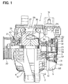
- Fig. 1 is a sectional view of a vehicle generator having a circuit protective cover according to a first embodiment of the present invention (taken on line I-I in Fig. 2);
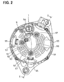
- Fig. 2 is a side view of the vehicle generator according to the first embodiment;
- Fig. 3A is a plan view of a protective cover according to the first embodiment;
- Fig. 3B is a partial sectional view of the protective cover taken on line IIIB-IIIB in Fig. 3A;
- Fig. 4A is a table showing data of mechanical properties required for the protective cover according to the first embodiment;
- Fig. 4B is a table showing data of mechanical properties of a conventional protective cover and of the protective cover according to the first embodiment;
- Fig. 4C is a graph of mechanical properties of the conventional protective cover;
- Fig. 4D is a graph of mechanical properties of the protective cover according to the first embodiment;
- Fig. 5A is a plan view of a protective cover according to a second embodiment of the present invention;
- Fig. 5B is a partial sectional view of the protective cover taken on line VB-VB in Fig. 5A;
- Fig. 6A is a plan view of a protective cover according to a third embodiment of the present invention; and
- Fig. 6B is a partial sectional view of the protective cover taken on line VIB-VIB in Fig. 6A.
-
- Figs. 1 and 2 depict a three-phase AC generator (alternator) 1 for an automobile according to the first embodiment of the present invention. An engine of the automobile drives the
AC generator 1 via a belt. TheAC generator 1 charges a storage battery and feeds electric power to respective electronic devices located on the automobile. TheAC generator 1 incorporates analternator 2 and anelectric circuit device 3 rectifying three-phase AC to DC. - The
alternator 2 has ahousing 4 including a drive-side aluminumfront end frame 41 and arear end frame 42, which are fixedly connected to each other. A pair ofbearings rotational shaft 21 of thealternator 2 to extend out of thehousing 4. Therotational shaft 21 secures apulley 22 driven via the belt by the engine at the front end thereof (left end in the figure) and also securesslip rings rotational shaft 2 secures arotor 24 at a middle portion thereof (to be enclosed in the housing 4). The internal surface of thehousing 4 secures a stator (armature, stator core) 25 to coaxially surround the outer periphery of therotor 24. - The
rotor 24 has a plurality of pole cores at a periphery portion thereof, and afield coil 26 at the central portion thereof. One end of thefield coil 26 is connected to an output terminal 14 of theAC generator 1, which is connected to the storage battery, and the other end of thefield coil 26 is grounded via a regulator. Thestator 25 has slots axially arranged at the internal circumference thereof, which installs anarmature coil 27 of thealternator 2, having a three-phase winding at a sixteen-polar full-pitch winding pitch. The three-phase terminals of thearmature 27 are connected via theelectric circuit device 3 to a positive terminal of the storage battery located outside the alternator system. - The
electric circuit device 3 is located behind therear end frame 42, and rectifies the three-phase AC induced in thearmature coil 27 to DC. Theelectric circuit device 3 is composed with arectifier 31, abrush 32, a holder holding thebrush 32, anIC regulator 34 and so on, and fixed onto the rear side of therear end frame 42 with screws. - As shown in Fig. 3A, a protective resin cover (that is: rear end cover) 5, which has a generally round pan shape and fixed coaxially to the
rear end frame 42, covers theelectric circuit device 3. Theprotective resin cover 5 consists of anouter periphery portion 51 rounding frontward and aflat portion 53 having multiple arc-shaped air vents 52. The outer periphery portion has aconnector cylinder 54 and a plurality ofprojections 55. Theflat portion 53 has abrush holding housing 56 and secures threemetallic plates 57, which are located coaxially at a predetermined interval and each of which has a screw hole for fixing theprotective resin cover 5 to thehousing 4. - The
protective resin cover 5 of this requires the mechanical properties shown in Fig. 4A, that is: the maximum elongation of 10% or higher; and the Charpy impact strength (with notch) of 78kJ/m2. It is desirable that the maximum elongation is 100% or higher. It is practical that Izod impact strength (23°C, with notch, 1/8 inch) is set between 500J/m and 2000J/m. These mechanical properties securely prevents theprotective resin cover 5 from fracturing and being detached from thehousing 4, by flexible deformation of theprotective resin cover 5 when the engine mounted on the vehicle chassis with rubber moves causing a secondary collision thereof with vehicle chassis, etc., in a case of a vehicular collision. Thus, theprotective resin cover 5 keeps the positive potential portion of theelectric circuit device 3 from contact with a ground portion of the vehicle not to cause sparks by a discharge of the electricity in the battery. - The left column in Fig. 4B and Fig. 4C shows a mechanical properties and a stress-strain curve of a conventional protective FRP cover made by mixing fiberglass with nylon-6,6 (PA66). The right column in Fig. 4B and Fig. 4D shows a mechanical properties and a stress-strain curve of the
protective resin cover 5 made by mixing elastomer with nylon-6,6 (PA66). - The
protective resin cover 5 of this embodiment endures a significantly large strain against the tensile stress, as shown in the stress-strain curve of Fig. 4D. The flexibility and the impact strength makes theprotective resin cover 5 deform in an instant at the secondary collision, securely preventing theprotective resin cover 5 from fracturing and being detached from thehousing 4. Thus, the flexibility and the impact strength reduce short-circuiting. - Figs. 5A and 5B depict a
protective cover 6 of an AC generator according to the second embodiment. Theprotective cover 6 hasextendable portions 61, which are arc-shaped lines projecting on an outer face and concaving on an inner face thereof, along the periphery of theprotective cover 6. Theprotective cover 6 may have a plurality of the arc-shaped lines aligning side by side in a radial direction of theprotective cover 6. ThisAC generator 1 keeps the positive potential portion of theelectric circuit device 3 from contact with the ground portion such as the vehicle chassis, by theextendable portion 61 deforming at the secondary impact to the vehicle chassis, etc., so as to prevent theprotective cover 6 from fracturing. - Figs. 6A and 6B depict a
protective cover 7 of an AC generator according to the third embodiment. Theprotective cover 7 has thin-walled portions 71, arc-shaped grooves inside the outer periphery portion thereof. A plurality of the thin-walled portions 71 may be provided to align side by side in a radial direction of theprotective cover 7. ThisAC generator 1 prevents theprotective cover 7 from fracturing at portions close to the positive potential portion, because theprotective cover 7 fractures selectively at the thin-walled portions 71 at the secondary impact to the vehicle chassis. Thus, theprotective cover 7 effectively prevents itself from fracturing at portions covering the positive potential portion of theelectric circuit device 3, which is required for electric insulation. - The AC generator according to the present invention serves to improve the safety by preventing uncovering the
electric circuit device 3, by preventing the protective cover (rear end cover) covering the positive potential portion of theelectric circuit device 3 from fracturing, even when theAC generator 1 suffers a secondary collision by a vehicular collision.
Claims (6)
- A generator (1) for a vehicle comprising:characterized in that the protective cover (5-7) is made of a composite material including a polyamide and an elastomer.a housing (4) enclosing a stator (25) on which an armature coil (27) is wound and a rotor (24) located inside the stator (25) to face each other;an electric circuit device (3) located outside the housing (4) for rectifying an AC induced in the armature coil (27) to a DC; anda protective cover (5-7) covering the electric circuit device (3),
- The generator (1) according to claim 1,
wherein the protective cover (5-7) has a mechanical properties including:a maximum elongation of 10% or higher; anda Charpy impact strength with notch of 78 kJ/m2 or higher. - A generator (1) for a vehicle comprising:characterized in that the protective cover (6) has at least one extendable portion (61), which is more flexible than other portions of the protective cover (6).a housing (4) enclosing a stator (25) on which an armature coil (27) is wound and a rotor (24) located inside of the stator (25) to face each other;an electric circuit device (3) located behind the housing (4) for rectifying an AC induced in the armature coil (27) to a DC; anda protective cover (6) covering the electric circuit device (3),
- A generator (1) for a vehicle comprising:characterized in that the protective cover (7) has at least one thin-walled portion (71), which fractures preceding the other portions of the protective cover (7).a housing (4) enclosing a stator (25) on which an armature coil (27) is wound and a rotor (24) located inside of the stator (25) to face each other;an electric circuit device (3) located behind the housing (4) for rectifying an AC induced in the armature coil (27) to DC; anda protective cover (7) covering the electric circuit device (3);
- The generator (1) according to claim 3,
wherein the extendable portion (6) has an arc-shape extending on a peripheral portion of the protective cover (6). - The generator (1) according to claim 4,
wherein the thin-walled portion (7) has an arc-shape extending on a peripheral portion of the protective cover (7).
Applications Claiming Priority (2)
| Application Number | Priority Date | Filing Date | Title |
|---|---|---|---|
| JP2004006960A JP2005204385A (en) | 2004-01-14 | 2004-01-14 | AC generator for vehicles |
| JP2004006960 | 2004-01-14 |
Publications (2)
| Publication Number | Publication Date |
|---|---|
| EP1555736A1 true EP1555736A1 (en) | 2005-07-20 |
| EP1555736B1 EP1555736B1 (en) | 2007-08-01 |
Family
ID=34616864
Family Applications (1)
| Application Number | Title | Priority Date | Filing Date |
|---|---|---|---|
| EP04029478A Expired - Lifetime EP1555736B1 (en) | 2004-01-14 | 2004-12-13 | Vehicle generator having circuit protective cover |
Country Status (5)
| Country | Link |
|---|---|
| US (1) | US6979921B2 (en) |
| EP (1) | EP1555736B1 (en) |
| JP (1) | JP2005204385A (en) |
| CN (1) | CN1324788C (en) |
| DE (1) | DE602004007871T2 (en) |
Cited By (1)
| Publication number | Priority date | Publication date | Assignee | Title |
|---|---|---|---|---|
| CN102280963A (en) * | 2011-08-31 | 2011-12-14 | 重庆长安汽车股份有限公司 | Driving motor of pure electric automobile |
Families Citing this family (8)
| Publication number | Priority date | Publication date | Assignee | Title |
|---|---|---|---|---|
| DE102005039884A1 (en) * | 2005-08-23 | 2007-03-08 | BSH Bosch und Siemens Hausgeräte GmbH | Rotor cover and electric motor |
| JP4609333B2 (en) * | 2006-02-01 | 2011-01-12 | トヨタ自動車株式会社 | Vehicle shock absorption structure |
| JP4775654B2 (en) * | 2006-10-03 | 2011-09-21 | 株式会社デンソー | AC generator for vehicles |
| JP4859788B2 (en) * | 2007-08-16 | 2012-01-25 | 日立オートモティブシステムズ株式会社 | AC generator for vehicles |
| JP5395192B2 (en) * | 2009-11-24 | 2014-01-22 | 三菱電機株式会社 | AC generator for vehicles |
| JP5345164B2 (en) * | 2011-02-16 | 2013-11-20 | 三菱電機株式会社 | Rotating electric machine for vehicles |
| JP5795086B2 (en) * | 2012-01-10 | 2015-10-14 | 三菱電機株式会社 | AC generator for vehicles |
| JP5894030B2 (en) * | 2012-07-20 | 2016-03-23 | アスモ株式会社 | motor |
Citations (6)
| Publication number | Priority date | Publication date | Assignee | Title |
|---|---|---|---|---|
| GB2107130A (en) * | 1981-09-08 | 1983-04-20 | Bosch Gmbh Robert | Improvements in or relating to alternating current generators having air-cooled rectifiers |
| US4546280A (en) * | 1983-01-08 | 1985-10-08 | Robert Bosch Gmbh | Alternator with unitary brush-holder and bearing hub |
| JPS62250053A (en) * | 1986-04-22 | 1987-10-30 | Mitsubishi Petrochem Co Ltd | Polyamide resin composition |
| JPH04198354A (en) * | 1990-11-28 | 1992-07-17 | Toray Ind Inc | Production of thermoplastic resin composition |
| DE19752672C1 (en) * | 1997-11-28 | 1999-03-04 | Buhler Motor Gmbh | Setting drive housing |
| FR2800928A1 (en) * | 1999-11-04 | 2001-05-11 | Valeo Equip Electr Moteur | Vehicle alternator has end cap with ventilating slits arranged in arcs of circle around shaft, each slit being provided with curved plates which deflect air radially towards the periphery of the cap |
Family Cites Families (9)
| Publication number | Priority date | Publication date | Assignee | Title |
|---|---|---|---|---|
| US4076989A (en) * | 1976-07-02 | 1978-02-28 | General Motors Corporation | Housing and stator assembly for a dynamoelectric machine |
| DE2847501A1 (en) * | 1978-11-02 | 1980-05-14 | Bosch Gmbh Robert | ELECTRIC GENERATOR |
| DE2848410A1 (en) * | 1978-11-08 | 1980-05-29 | Bosch Gmbh Robert | COVER FOR ELECTRICAL MACHINES |
| JPS62221839A (en) * | 1986-03-20 | 1987-09-29 | Hitachi Ltd | Ac generator for motor car |
| DE3717180A1 (en) * | 1987-05-22 | 1988-12-08 | Licentia Gmbh | ELECTRIC MOTOR WITH ATTACHED TACHOGENERATOR |
| US5296772A (en) * | 1993-04-05 | 1994-03-22 | General Motors Corporation | Ventilated brush holder |
| JP3820712B2 (en) * | 1997-11-27 | 2006-09-13 | 株式会社デンソー | AC generator for vehicles |
| JP4427896B2 (en) * | 2000-03-17 | 2010-03-10 | 株式会社デンソー | Vehicle alternator |
| CA2441622C (en) * | 2001-03-16 | 2010-06-08 | Altech Generating Systems Llc | Alternator and method of manufacture |
-
2004
- 2004-01-14 JP JP2004006960A patent/JP2005204385A/en active Pending
- 2004-12-03 US US11/002,492 patent/US6979921B2/en not_active Expired - Lifetime
- 2004-12-13 DE DE602004007871T patent/DE602004007871T2/en not_active Expired - Lifetime
- 2004-12-13 EP EP04029478A patent/EP1555736B1/en not_active Expired - Lifetime
-
2005
- 2005-01-14 CN CNB2005100043332A patent/CN1324788C/en not_active Expired - Lifetime
Patent Citations (6)
| Publication number | Priority date | Publication date | Assignee | Title |
|---|---|---|---|---|
| GB2107130A (en) * | 1981-09-08 | 1983-04-20 | Bosch Gmbh Robert | Improvements in or relating to alternating current generators having air-cooled rectifiers |
| US4546280A (en) * | 1983-01-08 | 1985-10-08 | Robert Bosch Gmbh | Alternator with unitary brush-holder and bearing hub |
| JPS62250053A (en) * | 1986-04-22 | 1987-10-30 | Mitsubishi Petrochem Co Ltd | Polyamide resin composition |
| JPH04198354A (en) * | 1990-11-28 | 1992-07-17 | Toray Ind Inc | Production of thermoplastic resin composition |
| DE19752672C1 (en) * | 1997-11-28 | 1999-03-04 | Buhler Motor Gmbh | Setting drive housing |
| FR2800928A1 (en) * | 1999-11-04 | 2001-05-11 | Valeo Equip Electr Moteur | Vehicle alternator has end cap with ventilating slits arranged in arcs of circle around shaft, each slit being provided with curved plates which deflect air radially towards the periphery of the cap |
Non-Patent Citations (2)
| Title |
|---|
| DATABASE WPI Section Ch Week 198749, Derwent World Patents Index; Class A17, AN 1987-345608, XP002322841 * |
| DATABASE WPI Section Ch Week 199235, Derwent World Patents Index; Class A23, AN 1992-289082, XP002322840 * |
Cited By (2)
| Publication number | Priority date | Publication date | Assignee | Title |
|---|---|---|---|---|
| CN102280963A (en) * | 2011-08-31 | 2011-12-14 | 重庆长安汽车股份有限公司 | Driving motor of pure electric automobile |
| CN102280963B (en) * | 2011-08-31 | 2013-04-03 | 重庆长安汽车股份有限公司 | Driving motor of pure electric automobile |
Also Published As
| Publication number | Publication date |
|---|---|
| CN1641973A (en) | 2005-07-20 |
| US6979921B2 (en) | 2005-12-27 |
| JP2005204385A (en) | 2005-07-28 |
| DE602004007871T2 (en) | 2008-04-17 |
| DE602004007871D1 (en) | 2007-09-13 |
| US20050151435A1 (en) | 2005-07-14 |
| EP1555736B1 (en) | 2007-08-01 |
| CN1324788C (en) | 2007-07-04 |
Similar Documents
| Publication | Publication Date | Title |
|---|---|---|
| US6700243B2 (en) | Automotive alternator | |
| US6979921B2 (en) | Vehicle generator having circuit protective cover | |
| US6747384B2 (en) | Alternator hybrid magnet rotor design | |
| JP3944357B2 (en) | AC generator for vehicles | |
| US20120126638A1 (en) | Automotive alternator rectifying apparatus | |
| US7141900B2 (en) | Connector case for vehicle ac generator | |
| US6744165B2 (en) | High power permanent magnet hybrid alternator rotor | |
| US7038340B2 (en) | Bearing device and AC generator for vehicles using the same | |
| US6674203B2 (en) | Vehicle rotary electric machine | |
| US6867517B2 (en) | Rectifier for alternator having rectifier element covered with rectifier terminal | |
| US6958557B2 (en) | Vehicle ac generator | |
| EP1783881B1 (en) | Voltage controller of ac generator | |
| CN104040843B (en) | Vehicle-mounted dlternator | |
| EP1496599B1 (en) | Ac generator for vehicle | |
| US6969935B2 (en) | Vehicle alternator | |
| JP2008054428A (en) | AC generator for vehicles | |
| US7498669B2 (en) | Semiconductor device | |
| JP4483842B2 (en) | Vehicle alternator | |
| KR20090129663A (en) | Car alternator | |
| JP4400010B2 (en) | Rotating electric machine | |
| JP2003189535A (en) | Electric rotating machine for vehicles | |
| KR200272503Y1 (en) | Combination structure of rectifier and voltage regulator of AC generator |
Legal Events
| Date | Code | Title | Description |
|---|---|---|---|
| PUAI | Public reference made under article 153(3) epc to a published international application that has entered the european phase |
Free format text: ORIGINAL CODE: 0009012 |
|
| AK | Designated contracting states |
Kind code of ref document: A1 Designated state(s): AT BE BG CH CY CZ DE DK EE ES FI FR GB GR HU IE IS IT LI LT LU MC NL PL PT RO SE SI SK TR |
|
| AX | Request for extension of the european patent |
Extension state: AL BA HR LV MK YU |
|
| 17P | Request for examination filed |
Effective date: 20050527 |
|
| AKX | Designation fees paid |
Designated state(s): DE FR GB |
|
| 17Q | First examination report despatched |
Effective date: 20050928 |
|
| GRAP | Despatch of communication of intention to grant a patent |
Free format text: ORIGINAL CODE: EPIDOSNIGR1 |
|
| GRAS | Grant fee paid |
Free format text: ORIGINAL CODE: EPIDOSNIGR3 |
|
| GRAA | (expected) grant |
Free format text: ORIGINAL CODE: 0009210 |
|
| AK | Designated contracting states |
Kind code of ref document: B1 Designated state(s): DE FR GB |
|
| REG | Reference to a national code |
Ref country code: GB Ref legal event code: FG4D |
|
| REF | Corresponds to: |
Ref document number: 602004007871 Country of ref document: DE Date of ref document: 20070913 Kind code of ref document: P |
|
| ET | Fr: translation filed | ||
| REG | Reference to a national code |
Ref country code: GB Ref legal event code: 746 Effective date: 20080425 |
|
| PLBE | No opposition filed within time limit |
Free format text: ORIGINAL CODE: 0009261 |
|
| STAA | Information on the status of an ep patent application or granted ep patent |
Free format text: STATUS: NO OPPOSITION FILED WITHIN TIME LIMIT |
|
| 26N | No opposition filed |
Effective date: 20080506 |
|
| REG | Reference to a national code |
Ref country code: FR Ref legal event code: PLFP Year of fee payment: 12 |
|
| REG | Reference to a national code |
Ref country code: FR Ref legal event code: PLFP Year of fee payment: 13 |
|
| REG | Reference to a national code |
Ref country code: FR Ref legal event code: PLFP Year of fee payment: 14 |
|
| PGFP | Annual fee paid to national office [announced via postgrant information from national office to epo] |
Ref country code: GB Payment date: 20231220 Year of fee payment: 20 |
|
| PGFP | Annual fee paid to national office [announced via postgrant information from national office to epo] |
Ref country code: FR Payment date: 20231221 Year of fee payment: 20 Ref country code: DE Payment date: 20231214 Year of fee payment: 20 |
|
| REG | Reference to a national code |
Ref country code: DE Ref legal event code: R071 Ref document number: 602004007871 Country of ref document: DE |
|
| REG | Reference to a national code |
Ref country code: GB Ref legal event code: PE20 Expiry date: 20241212 |
|
| PG25 | Lapsed in a contracting state [announced via postgrant information from national office to epo] |
Ref country code: GB Free format text: LAPSE BECAUSE OF EXPIRATION OF PROTECTION Effective date: 20241212 |
|
| PG25 | Lapsed in a contracting state [announced via postgrant information from national office to epo] |
Ref country code: GB Free format text: LAPSE BECAUSE OF EXPIRATION OF PROTECTION Effective date: 20241212 |