EP1555629B1 - Akustischer Berührungsbildschirm mit einer Gruppe von Reflektoren die derart geformt sind, dass sie die Energie der akustischen Welle fokussieren - Google Patents
Akustischer Berührungsbildschirm mit einer Gruppe von Reflektoren die derart geformt sind, dass sie die Energie der akustischen Welle fokussieren Download PDFInfo
- Publication number
- EP1555629B1 EP1555629B1 EP05100046A EP05100046A EP1555629B1 EP 1555629 B1 EP1555629 B1 EP 1555629B1 EP 05100046 A EP05100046 A EP 05100046A EP 05100046 A EP05100046 A EP 05100046A EP 1555629 B1 EP1555629 B1 EP 1555629B1
- Authority
- EP
- European Patent Office
- Prior art keywords
- array
- reflective
- elements
- touchscreen
- substrate
- Prior art date
- Legal status (The legal status is an assumption and is not a legal conclusion. Google has not performed a legal analysis and makes no representation as to the accuracy of the status listed.)
- Expired - Lifetime
Links
Images


Classifications
-
- G—PHYSICS
- G06—COMPUTING OR CALCULATING; COUNTING
- G06F—ELECTRIC DIGITAL DATA PROCESSING
- G06F3/00—Input arrangements for transferring data to be processed into a form capable of being handled by the computer; Output arrangements for transferring data from processing unit to output unit, e.g. interface arrangements
- G06F3/01—Input arrangements or combined input and output arrangements for interaction between user and computer
- G06F3/03—Arrangements for converting the position or the displacement of a member into a coded form
- G06F3/041—Digitisers, e.g. for touch screens or touch pads, characterised by the transducing means
- G06F3/043—Digitisers, e.g. for touch screens or touch pads, characterised by the transducing means using propagating acoustic waves
- G06F3/0436—Digitisers, e.g. for touch screens or touch pads, characterised by the transducing means using propagating acoustic waves in which generating transducers and detecting transducers are attached to a single acoustic waves transmission substrate
Definitions
- the present invention relates to acoustic touchscreens and, in particular, to acoustic touchscreens employing focusing-shaped reflective arrays to transmit and receive acoustic signals into and out of a touch-sensitive area.
- FIG. 1 illustrates the operation of a conventional acoustic touchscreen 1 having an active or "touch-sensitive" area 2.
- a first transmitting transducer 3a is positioned outside of the touch-sensitive area 2 and acoustically coupled to the surface of touchscreen 1.
- the transducer 3a sends an acoustic signal in the form of an acoustic wave (or beam) 11a traveling parallel to the top edge, and generally in the plane of, touchscreen 1.
- a first linear array 13 of acoustically reflective elements 4 Aligned in the transmission path of acoustic wave 11a is a first linear array 13 of acoustically reflective elements 4, each of which partially reflects (by approximately 90 degrees) and partially transmits (i.e., passes through) the acoustic wave 11a, creating a plurality of acoustic waves (exemplary ones shown as 5a, 5b, and 5c) traveling vertically (parallel to the Y-axis) across touch-sensitive area 2.
- an "acoustically reflective" element includes any element which at least partially reflects acoustic wave energy, even if such element may actually pass through nearly all of the wave energy.
- an individual reflective array element reflects as little as 1% or less of an acoustic wave into the touch-sensitive area, while passing through the remaining wave energy to the next successive array element.
- the spacing of the reflective array elements 4 is variable to compensate for the attenuation of the acoustic waves with increasing distance from first transmitter 3a. Alternately, such compensation may be provided by densely spaced reflective array elements with variable reflective strengths.
- the acoustic waves 5a, 5b, and 5c are again reflected by approximately 90 degrees (shown by arrow 11b) by a second linear array 13 of acoustically reflective elements 4 towards a first receiving transducer 6a, where they are detected and converted to electrical signals for data processing.
- a first receiving transducer 6a along the left and right edges of touchscreen 1 are located a similar arrangement.
- a second transmitting transducer 3b generates an acoustic wave 12a along the left edge, and a third linear array 13 of acoustically reflective elements 4 creates therefrom a plurality of acoustic waves (exemplary 7a, 7b, and 7c) traveling horizontally (parallel to the X-axis) across touch-sensitive area 2. Acoustic waves 7a, 7b, and 7c are redirected (arrow 12b) by a fourth linear array 13 of acoustically reflective elements 4 towards receiving transducer 6b, where they are detected and converted to electrical signals.
- a touchscreen without one set of transducers, will still function as a touchscreen, detecting the occurrence of a touch and providing limited location information (i.e., one of the coordinates).
- a touchscreen can be designed with only two transducers by using a common transmit/receive transducer scheme as shown in Fig. 11 of U.S. Patent No. 4,880,665 .
- a bezel overlays the touchscreen 1, concealing the transmitting and receiving transducers, the reflective elements, and other components, and defining the touch-sensitive area 2.
- This arrangement protects the concealed components from contamination and/or damage, presents a more aesthetically pleasing appearance, and defines the touch-sensitive area for the user.
- the touch-sensitive area 2 is surrounded by border regions 15 (only two labeled), where the reflective elements 4 and the transmitting and receiving transducers 3a, 3b, 6a, and 6b are located. Reducing the width of border regions 15 increases the percentage of the frontal area of the device that may be allocated to touch-sensitive area 2, as well as conveying a less cumbersome, sleeker design.
- U.S. Patent 6,636,201 discloses acoustic touchscreens having relatively narrower border regions 15. The key to reducing their width lies with reducing the width of arrays 13 and the transducers (3a, 3b, 6a, 6b).
- FIG. 2 illustrates a transducer 16 and a reflective array 13 of an acoustic touchscreen that allows for a narrower border region than in conventional touchscreens.
- the path of the acoustic wave 11a is confined by an acoustic waveguide core 18.
- the reflective array 13 includes a plurality of acoustically reflective elements 14 cooperating with the waveguide core 18.
- the reflective elements 14 are overlaid on top of the waveguide core 18 at predetermined intervals, which effectively allows the reflective elements 14 to partially deflect energy from the incoming acoustic wave 11a across the touch-sensitive area as the acoustic waves 5a and 5b.
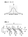
- a significant portion of the acoustic energy is confined to the array 14 of width w as a result of the inclusion of the waveguide core 18 of width y. Because the width of the acoustic wave energy can be controlled by the width of the waveguide core 18, the reflectors 14 may be made correspondingly narrower than conventional ones, but yet deflect a sufficient amount of acoustic energy across the touch-sensitive area for touch-sensing purposes
- a touchscreen comprising: a substrate capable of propagating acoustic waves, the substrate having a touch-sensitive area; and an array of acoustically reflective elements lying in or on the substrate, the array having an axis, the reflective array elements positioned at an angle relative to the array axis to reflect acoustic signals into the touch-sensitive area or reflect acoustic signals received from the touch-sensitive area, characterised by the reflective array elements having a focusing shape that serves to focus acoustic wave energy passing through the elements to an area proximate a senter line axis of the array.
- a "focusing-shaped" reflective array element is one that tends to focus the portion (typically most all) of the acoustic wave energy being passed through the respective element to an area proximate a center line axis of the array.
- the focusing-shaped elements are located on or in the touchscreen substrate in the path of the acoustic wave energy, and have a velocity-slowing effect, or equivalently a phase-delaying effect, relative to the surrounding touchscreen substrate.
- Each element's velocity-slowing effect strengthens proximate its center by varying one or both of its width and height along its transverse dimension, (i.e., along its dimension transverse to the propagating wave energy), with a maximum width and/or height proximate its center, tapering to a minimum width and/or height at its transverse ends.
- the natural divergence of the wave energy is countered by the tendency of the elements to pull the wave energy towards the center line of the array axis, where the maximum propagation delay through the respective elements is encountered.
- the focusing-shaped elements provide waveguide functionality without requiring a separate waveguide core structure.
- a touchscreen in an exemplary embodiment, includes a substrate capable of propagating acoustic waves and having a touch-sensitive area.
- a linear array of focusing-shaped acoustically reflective elements is provided lying in or on the substrate and positioned to transmit or receive acoustic signals into or out of the touch-sensitive area.
- the reflective elements may have a varying width dimension, with a maximum width proximate their center.
- the reflective elements may have a varying height dimension, with a maximum height proximate their center.
- the reflective elements are grooves located in a surface of the substrate and positioned at an angle relative to an array axis, each element having a having a varying depth from the substrate surface, with a maximum depth proximate its center.
- the groves may be at least partially filled with a medium having a different (i.e., slower) acoustic wave propagation speed than the substrate medium.
- the reflective array elements may be located on a surface of, or partially or fully embedded in, the substrate.
- the touchscreen further includes a waveguide core substantially aligned with the reflective array axis.
- FIG. 1 is a schematic plan view of a conventional acoustic touchscreen.
- FIG. 2 is a waveguide-reflective array combination for use in an acoustic touchscreen.
- FIG. 3 is a schematic graph of acoustic energy along the width of the waveguide-reflective array of FIG. 2 .
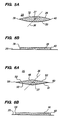
- FIG. 4 is a plan view of an exemplary embodiment of a focusing-shaped reflective array in accordance with the present invention.
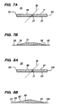
- FIGS. 5A and 5B are plan and side views, respectively, of a focusing-shaped reflective element of the array of FIG. 4 .
- FIGS. 6A and 6B are plan and side views of an alternate embodiment of a focusing-shaped reflective element for use in the array of FIG. 4 .
- FIGS. 7A and 7B are plan and side views of another embodiment of a focusing-shaped reflective element for use in the array of FIG. 4 .
- FIGS. 8A and 8B are plan and side views of yet another embodiment of a focusing-shaped reflective element for use in the array of FIG. 4 .
- FIGS. 9A and 9B are sectional side views of still further embodiments of focusing-shaped reflective array elements for use in the array of FIG. 4 .
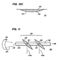
- FIGS. 10A, 10B and 10C are sectional side views of yet further embodiments of focusing reflective array elements for use in the array of FIG. 4 .
- FIG. 11 is a plan view of a further exemplary embodiment of a focusing-shaped reflective array cooperating with a waveguide core in accordance with a further aspect of the present invention.
- FIG. 4 illustrates a transducer 22 and a linear reflective array 24 for use in transmitting an acoustic beam 34 emitted from the transducer 22 across a touch-sensitive area (not shown) of an acoustic-touchscreen (e.g., glass) substrate 25.
- the reflective array 24 includes a plurality of acoustically reflective focusing-shaped elements 26.
- the reflective elements 26 are lens-shaped, i.e., having a parabolic profile, and are positioned at an angle (approximately 45 degrees) relative to an axis 28 of the reflective array 24.
- Each reflective element 26 has a proximal facing convex surface 30 and a distal facing convex surface 32, the respective surfaces 30 and 32 tapering to respective transverse ends 39 and 40 of the element 26.
- FIGS. 5A and 5B are plan and side views of the array elements 26 shown in FIG. 4 , which are formed on a surface of the substrate 25.
- the array axis 28 is aligned with the transmission path of the acoustic beam 34, such that each element 26 partially reflects (by approximately 90 degrees) and partially transmits (i.e., passes through) the acoustic beam 34, creating a plurality of acoustic waves (exemplary ones shown as 34a, 34b, and 34c) traveling into the touch-sensitive area (not shown). Because of the focusing-shape of the reflective elements 26, that portion (typically nearly all) of the energy of the acoustic beam 34 passing through the respective elements 26 is focused to a relatively narrow area proximate a center line 36 passing through a center point 37 of each of the respective elements 26 and parallel to the array axis 28.
- each element imposes a velocity-slowing effect on the acoustic beam 34, which strengthens proximate its respective center point 37.
- This may be accomplished by varying one or both of a width or height of the element 26 along its transverse dimension, i.e., along that dimension transverse to the propagating wave energy, with a maximum width and/or height proximate its center 37, tapering to a minimum width and/or height at its transverse ends 39, 40.
- the natural divergence of the wave energy is countered by the tendency of the elements to pull the wave energy of the beam 34 towards the center line 36 of the array axis 28, where the maximum propagation delay through the respective elements 26 is encountered.
- the reflective array elements 26 do not so much focus the acoustic beam 34, but instead effectively cancel the de-focusing effect of the natural diffractive spreading of the beam 34, so that the transverse width of the beam 34 (i.e., relative to the array axis 28) remains substantially the same when it reaches each successive reflective element 26 in the array 24.
- the elements 26 may be made correspondingly narrower than in conventional reflective arrays used in acoustic touchscreens, but still deflect a sufficient amount of acoustic energy across the touch-sensitive area of the substrate 25 for touch-sensing purposes.
- the wave energy of the acoustic beam 34 propagates in the substrate 25, with a significant power density at the surface.
- the propagation of the acoustic beam 34 is described herein as being two-dimensional in the surface of the substrate 25.
- the reflective array elements 26 located on or near the surface sufficiently interact with the wave energy to affect wave propagation velocities as described above, thereby "focusing" the energy of the beam 34 proximate the center line 36 of the array axis 28.
- the transmitting transducer 22 can be a focusing transducer, in which the beam 34 of acoustic waves comes to a focus at a focal location 38 proximate the center of the proximal surface 30 of the most proximal element 26. Because the wave energy in beam 34 is not precise, the focal location 38 is not a mathematical spot, but rather a "neck" in the width of the beam 34. If the respective reflective array elements 26 were not in the path of the acoustic beam 34, it would diverge after the focal neck 38.
- a receiving transducer may also be a focusing type, with similar advantages.
- a focusing transducer will be applicable to further embodiments of the invention, both illustrated and not illustrated herein. For purposes of brevity, however, it will not be specifically discussed in each instance.
- FIGS. 6A and 6B illustrate an alternate focusing-shaped element 46 that may be formed on the touchscreen substrate 25 for use in the reflective array 24 of FIG. 4 , the element 46 having a diamond shape in plan view.
- the element 46 has a pair of proximal facing flat surfaces 50 and 51, which are angled proximally from respective ends 59 and 60 away from center 37.
- a pair of distal facing flat surfaces 52 and 53 is angled distally from the respective ends 59 and 60, away from the center 37.
- the resultant phase delay profile of the portion of the acoustic beam 34 passing through element 46 will be "focused" to an area proximate center line 36.
- FIGS. 7A-B and 8A-B illustrate further alternate focusing-shaped elements 66 and 86, respectively, that may be formed on the touchscreen substrate 25 for use in the reflective array 24 of FIG. 4 .
- reflective elements 66 and 86 each have a varying height dimension, as opposed to the varying width dimension of reflective elements 26 and 46, with element 66 having a parabolic height profile and element 86 having a triangular height profile.
- element 66 has flat proximal and distal facing surfaces 70 and 71, with a parabolic top surface 72.
- the top surface 72 has a maximum height proximate a center 37 of the element 66, tapering to the surface of the substrate 25 at respective ends 79 and 80.
- element 86 has flat proximal and distal facing surfaces 90 and 91, with a pair of flat top surfaces 82 and 83 extending from the surface of the substrate 25 at ends 99 and 100 to meet at a maximum height proximate a center 37 of the element 86.
- elements 66 and 86 may optionally also have a varying width dimension.
- focusing-shaped reflective elements in a single array may include elements with one or both of a varying width dimension and a varying height dimension, with one or both of a maximum width and a maximum height proximate a center of the respective element.
- acoustic touchscreens may employ waves other than Rayleigh waves, such as shear and Lamb waves, or combinations of different types of acoustic waves (including combinations involving Rayleigh waves).
- Shear waves e.g., ZOHPS and HOHPS
- Lamb waves have significant acoustic power density at both the top and bottom surfaces of the substrate in which they travel.
- the particular focusing-shaped reflective elements in a particular array and/or touchscreen may be formed differently, e.g., with some located on a surface, and others partially or fully embedded in the touchscreen substrate.
- FIGS. 9A and 9B illustrate further focusing-shaped elements 106 and 126, respectively, which are formed partially embedded in the touchscreen substrate 25, and which may be used in reflective array 24 of FIG. 4 .
- the reflective elements 106 and 126 each have a varying height dimension along a transverse length, but with element 106 having a full parabolic side profile and element 126 having a diamond-shaped side profile.
- element 106 has top and bottom parabolic surfaces 108 and 110, respectively.
- the top surface 108 has a maximum height, and the bottom surface 110 a maximum depth, respectively, relative to the surface of the substrate 25 proximate a center of the element 106.
- element 126 has a pair of flat top surfaces 122 and 124, which extend from the substrate 25 to meet at a maximum height proximate a center of the element 126, and a pair of flat bottom surfaces 118 and 120, which extend from the substrate 25 to meet at a maximum depth proximate the center.
- Elements 106 and/or 126 may optionally also have a varying width dimension. As with the previously described focusing-shaped reflective array elements, the resultant phase delay profile of the portion of an acoustic wave passing through elements 106 and 126 will be focused within an area proximate the center line 36 of the array axis 28.
- FIGS. 10A, 10B and 10C illustrate still further focusing-shaped elements 146, 156 and 166, respectively, which may be used in reflective array 24 of FIG. 4 .
- elements 146, 156 and 166 are grooves formed in a surface of the substrate 25, each having a varying depth dimension relative to the surface of the substrate 25.
- Elements 146 and 166 each have a half-parabolic side profile, and element 156 has a triangular side profile. More particularly, with reference to FIG. 10A , element 146 has a parabolic bottom surface 142, with a maximum depth relative to the surface of the substrate 25 proximate its center. With reference to FIG.
- element 156 has a pair of flat bottom surfaces 152 and 154, which extend from the substrate 25 to meet at a maximum depth proximate the center of the element 156.
- element 166 has a parabolic bottom surface 164, with a maximum depth relative to the surface of the substrate 25 proximate its center.
- Element 166 is similar to element 146, except that element 146 is empty, whereas element 166 is substantially filled with a medium 168 different (i.e., and having a slower wave propagation speed) than the substrate medium. Examples of such mediums include glass and/or silver-loaded glass frit, as well as polymer inks, such as those disclosed in U.S. Patents Nos.
- elements 146, 156 and/or 166 may optionally also have a varying width dimension. As with the previously described focusing-shaped reflective array elements, the resultant phase delay profile of the portion of an acoustic wave passing through elements 146, 156 and 166 will be focused within an area proximate the center line 36 of the array axis 28.
- focusing-shaped reflective array provides waveguide functionality, it may be desirable in certain embodiments to further employ a waveguide core, along with a focusing-shaped reflective array, in the acoustic transmission path.
- FIG. 11 which includes a focusing transducer 182 and a focusing-shaped reflective array 184 in cooperation with a waveguide core 200 for transmitting an acoustic beam 194 emitted from the transducer 182 across a touch-sensitive area (not shown) of an acoustic touchscreen substrate 185.
- the reflective array 184 includes a plurality of acoustically reflective, lens-shaped elements 186, similar to elements 26 in the embodiment of FIG. 4 , which are positioned at an angle (approximately 45 degrees) relative to an axis 188 of the reflective array 184.
- the waveguide core 200 and array axis 188 are aligned with the transmission path of the acoustic beam 194, such that each element 186 partially reflects (by approximately 90 degrees) and partially transmits (i.e., passes through) the acoustic beam 194, creating a plurality of acoustic waves (exemplary ones shown 194a and 194b) traveling into the touch-sensitive area (not shown).
- Both the waveguide core 200 and the focusing-shape of the array elements 186 cause that portion of the energy of the acoustic beam 194 which passes through the centers 187 of the respective elements 186 to be focused within a transmission area proximate a center line 196.
- the focusing transducer 182 generates the beam 194 of acoustic waves that come to a focus at a focal point 198 proximate center line 196 at the entrance of the waveguide core 200.
- the waveguide core 200 and reflective array elements 186 may be coupled to and/or partially or fully embedded in the same or different surfaces of the touchscreen substrate 185.
- the reflective array elements 186 may be positioned underlying or overlaying the waveguide core 200. Exemplary constructions of a waveguide core and reflective elements are provided in the above-incorporated U.S. Patent 6,636,201 .
- the reflective array elements are focusing-shaped; but so long as at least some of the elements are focusing-shaped, those elements of such array comprise a focusing-shaped reflective array, as described and claimed herein.
- the mere inclusion of one or more non-focusing reflective elements does not preclude the array, or portions thereof, from functioning as a focusing-shaped reflective-element array.
Landscapes
- Engineering & Computer Science (AREA)
- Physics & Mathematics (AREA)
- General Engineering & Computer Science (AREA)
- Theoretical Computer Science (AREA)
- Acoustics & Sound (AREA)
- Human Computer Interaction (AREA)
- General Physics & Mathematics (AREA)
- Position Input By Displaying (AREA)
Claims (12)
- Berührungsbildschirm, der aufweist:ein Substrat (25), das akustische Wellen ausbreiten kann, wobei das Substrat (25) einen berührungsempfindlichen Bereich (2) aufweist; undeine Anordnung (24, 184) von akustisch reflektierenden Elementen (26, 186), die im oder auf dem Substrat (25) liegen, wobei die Anordnung (24, 184) eine Achse (28, 188) aufweist, wobei die reflektierenden Elemente (26, 186) der Anordnung unter einem Winkel relativ zur Anordnungsachse (28, 188) positioniert sind, um akustische Signale in den berührungsempfindlichen Bereich zu reflektieren, oder um akustische Signale zu reflektieren, die vom berührungsempfindlichen Bereich empfangen werden,gekennzeichnet dadurch, dass die reflektierenden Elemente (26, 186) der Anordnung eine fokussierende Form aufweisen, die dazu dient, die Energie der akustischen Wellen, die durch die Elemente hindurchgehen, zu einem Bereich in unmittelbarer Nähe einer Mittellinienachse (28, 188) der Anordnung zu fokussieren.
- Berührungsbildschirm nach Anspruch 1, dadurch gekennzeichnet, dass mindestens ein reflektierendes Element (26, 186) der Anordnung auf einer Oberfläche des Substrates (25) angeordnet oder mindestens teilweise im Substrat (25) eingebettet ist.
- Berührungsbildschirm nach Anspruch 1 oder 2, dadurch gekennzeichnet, dass mindestens ein reflektierendes Element (26, 186) der Anordnung eine der folgenden aufweist:(a) eine sich verändernde Breitenabmessung mit einer maximalen Breite in unmittelbarer Nähe seiner Mitte (37);(b) eine sich verändernde Höhenabmessung mit einer maximalen Höhe in unmittelbarer Nähe seiner Mitte (37);(c) sowohl eine sich verändernde Breitenabmessung als auch eine sich verändernde Höhenabmessung mit einer maximalen Breite und einer maximalen Höhe in unmittelbarer Nähe seiner Mitte (37); und(d) ein kegelförmiges Profil.
- Berührungsbildschirm nach Anspruch 1 oder 2, dadurch gekennzeichnet, dass mindestens ein reflektierendes Element (146, 156, 166) der Anordnung eine Nut (142, 152, 154, 164) mit einer sich verändernden Tiefe in einer Oberfläche des Substrates (25) mit einer maximalen Tiefe in unmittelbarer Nähe seiner Mitte aufweist, wobei das Substrat (25) vorzugsweise ein erstes Medium aufweist und die Nut mindestens teilweise mit einem zweiten Medium (168) gefüllt ist.
- Berührungsbildschirm nach Anspruch 1 oder 2, dadurch gekennzeichnet, dass mindestens ein reflektierendes Element (26, 186) der Anordnung ein parabolisches Profil aufweist, wobei vorzugsweise ein jedes des mindestens einen reflektierenden Elementes (26, 186) der Anordnung eine jeweilige proximal liegende und distal liegende konvexe Oberfläche (30, 32) aufweist.
- Berührungsbildschirm nach einem der vorhergehenden Ansprüche, dadurch gekennzeichnet, dass er außerdem einen Wellenleiterkern (200) aufweist, der im Wesentlichen mit der Anordnungsachse (28, 188) ausgerichtet ist.
- Berührungsbildschirm nach Anspruch 6, dadurch gekennzeichnet, dass die reflektierenden Elemente (26, 186) der Anordnung über dem Wellenleiterkern (200) oder unter dem Wellenleiterkern (200) liegen.
- Berührungsbildschirm nach Anspruch 1, wobei die Anordnung der akustisch reflektierenden Elemente (26, 186) aufweist:eine erste Anordnung (13, 24, 184) von akustisch reflektierenden Elementen (26, 186), die im oder auf dem Substrat (25) liegen und positioniert sind, um akustische Signale in den berührungsempfindlichen Bereich (2) zu reflektieren; undeine zweite Anordnung (13, 24, 184) von akustisch reflektierenden Elementen (26, 186), die im oder auf dem Substrat (25) liegen und positioniert sind, um akustische Signale zu reflektieren, die mittels der ersten Anordnung (13, 24, 184) reflektiert wurden, nachdem sich die akustischen Signale über den berührungsempfindlichen Bereich bewegt haben,wobei mindestens eines der Elemente (26, 186) der ersten und zweiten reflektierenden Anordnung eine fokussierende Form aufweist, die dazu dient, die Energie der akustischen Wellen, die durch die Elemente hindurchgehen, zu einem Bereich in unmittelbarer Nähe einer Mittellinienachse (28, 188) der Anordnung zu fokussieren.
- Berührungsbildschirm nach Anspruch 8, dadurch gekennzeichnet, dass die erste reflektierende Anordnung (24, 186) eine erste Anordnungsachse (28, 188) aufweist, dass die zweite reflektierende Anordnung (24, 186) eine zweite Anordnungsachse (28, 188) aufweist, der Berührungsbildschirm außerdem einen ersten Wandler (3a, 22, 182), der akustisch mit dem Substrat (25) verbunden und positioniert ist, um ein akustisches Signal entlang der ersten Anordnungsachse (28, 188) zu übertragen, und einen zweiten Wandler (3b, 22, 182) aufweist, der akustisch mit dem Substrat (25) verbunden und positioniert ist, um ein akustisches Signal zu empfangen, das sich längs der zweiten Anordnungsachse (28, 188) bewegt, wobei vorzugsweise einer oder beide von erstem und zweitem Wandler einen fokussierenden Wandler (22, 182) aufweisen.
- Berührungsbildschirm nach Anspruch 8, dadurch gekennzeichnet, dass der Berührungsbildschirm mindestens eine aufweist von:(a) der ersten reflektierenden Anordnung (13, 14, 184) mit einer ersten Anordnungsachse (28, 188), die außerdem einen Wellenleiterkern (200) aufweist, der im Wesentlichen mit der ersten Anordnungsachse ausgerichtet ist;(b) der zweiten reflektierenden Anordnung (13, 14, 184) mit einer zweiten Anordnungsachse (28, 188), die außerdem einen Wellenleiterkern (200) aufweist, der im Wesentlichen mit der zweiten Anordnungsachse ausgerichtet ist;(c) wobei ein jedes der Elemente (26, 186) der ersten und zweiten reflektierenden Anordnung eine fokussierende Form aufweist; und(d) wobei ein jedes der Elemente (26, 186) der ersten und zweiten reflektierenden Anordnung eine oder beide von einer sich verändernden Breitenabmessung und einer sich verändernden Höhenabmessung mit einer oder beiden von einer maximalen Breite und einer maximalen Höhe in unmittelbarer Nähe seiner Mitte (37) aufweist.
- Berührungsbildschirm nach Anspruch 8, dadurch gekennzeichnet, dass das Substrat (25) außerdem einen Grenzbereich (15) benachbart dem berührungsempfindlichen Bereich (2) aufweist,
wobei die erste Anordnung (13, 24, 184) der akustisch reflektierenden Elemente (26, 186) in einem ersten Abschnitt des Grenzbereiches (15) positioniert ist, wobei die erste Anordnung eine erste Anordnungsachse (28, 188) aufweist; und
wobei die zweite Anordnung (13, 24, 184) der akustisch reflektierenden Elemente (26, 186) in einem zweiten Abschnitt des Grenzbereiches (15) positioniert ist, wobei die zweite Anordnung eine zweite Anordnungsachse (28, 188) aufweist,
wobei die Elemente (26, 186) der ersten und zweiten reflektierenden Anordnung eine fokussierende Form aufweisen. - Berührungsbildschirm nach Anspruch 11, dadurch gekennzeichnet, dass er außerdem aufweist: einen ersten Wandler (3a, 22, 182), der akustisch mit dem Substrat (25) im ersten Abschnitt des Grenzbereiches (15) verbunden und positioniert ist, um ein akustisches Signal längs der ersten Anordnungsachse (28, 188) zu übertragen; und einen zweiten Wandler (3b, 22, 182), der akustisch mit dem Substrat (25) im zweiten Abschnitt des Grenzbereiches (15) verbunden und positioniert ist, um ein akustisches Signal zu empfangen, das sich längs der zweiten Anordnungsachse (28, 188) bewegt.
Applications Claiming Priority (2)
| Application Number | Priority Date | Filing Date | Title |
|---|---|---|---|
| US10/752,935 US7274358B2 (en) | 2004-01-06 | 2004-01-06 | Focusing-shaped reflector arrays for acoustic touchscreens |
| US752935 | 2004-01-06 |
Publications (3)
| Publication Number | Publication Date |
|---|---|
| EP1555629A2 EP1555629A2 (de) | 2005-07-20 |
| EP1555629A3 EP1555629A3 (de) | 2006-11-15 |
| EP1555629B1 true EP1555629B1 (de) | 2012-03-07 |
Family
ID=34620653
Family Applications (1)
| Application Number | Title | Priority Date | Filing Date |
|---|---|---|---|
| EP05100046A Expired - Lifetime EP1555629B1 (de) | 2004-01-06 | 2005-01-05 | Akustischer Berührungsbildschirm mit einer Gruppe von Reflektoren die derart geformt sind, dass sie die Energie der akustischen Welle fokussieren |
Country Status (5)
| Country | Link |
|---|---|
| US (1) | US7274358B2 (de) |
| EP (1) | EP1555629B1 (de) |
| JP (1) | JP4604224B2 (de) |
| CN (1) | CN100565656C (de) |
| TW (1) | TWI352918B (de) |
Families Citing this family (29)
| Publication number | Priority date | Publication date | Assignee | Title |
|---|---|---|---|---|
| CN101373415B (zh) * | 2007-08-21 | 2010-06-02 | 禾瑞亚科技股份有限公司 | 表面声波式触控面板的感测装置 |
| US11327599B2 (en) | 2011-04-26 | 2022-05-10 | Sentons Inc. | Identifying a contact type |
| US10198097B2 (en) | 2011-04-26 | 2019-02-05 | Sentons Inc. | Detecting touch input force |
| US9477350B2 (en) | 2011-04-26 | 2016-10-25 | Sentons Inc. | Method and apparatus for active ultrasonic touch devices |
| US9639213B2 (en) | 2011-04-26 | 2017-05-02 | Sentons Inc. | Using multiple signals to detect touch input |
| US9189109B2 (en) | 2012-07-18 | 2015-11-17 | Sentons Inc. | Detection of type of object used to provide a touch contact input |
| US8681128B2 (en) | 2011-10-14 | 2014-03-25 | Elo Touch Solutions, Inc. | Acoustic touch apparatus |
| US8823685B2 (en) * | 2011-10-14 | 2014-09-02 | Elo Touch Solutions, Inc. | Acoustic touch apparatus |
| US9348467B2 (en) | 2011-11-15 | 2016-05-24 | Elo Touch Solutions, Inc. | Radial layout for acoustic wave touch sensor |
| US9304629B2 (en) | 2011-11-15 | 2016-04-05 | Elo Touch Solutions, Inc. | Radial transducer for acoustic wave touch sensor |
| KR101652744B1 (ko) | 2011-11-18 | 2016-09-09 | 센톤스 아이엔씨. | 국소형 햅틱 피드백 |
| WO2013075137A1 (en) | 2011-11-18 | 2013-05-23 | Sentons Inc. | Detecting touch input force |
| US10235004B1 (en) | 2011-11-18 | 2019-03-19 | Sentons Inc. | Touch input detector with an integrated antenna |
| US9524063B2 (en) | 2012-07-18 | 2016-12-20 | Sentons Inc. | Detection of a number of touch contacts of a multi-touch input |
| US9348468B2 (en) | 2013-06-07 | 2016-05-24 | Sentons Inc. | Detecting multi-touch inputs |
| US9513727B2 (en) | 2012-07-18 | 2016-12-06 | Sentons Inc. | Touch input surface microphone |
| US9128567B2 (en) | 2012-11-20 | 2015-09-08 | Elo Touch Solutions, Inc. | Segmented waveguide core touch sensor systems and methods |
| US9170686B2 (en) * | 2013-01-10 | 2015-10-27 | Elo Touch Solutions, Inc. | Multi-transducer waveguide arrays |
| US9588552B2 (en) | 2013-09-11 | 2017-03-07 | Sentons Inc. | Attaching electrical components using non-conductive adhesive |
| US9459715B1 (en) | 2013-09-20 | 2016-10-04 | Sentons Inc. | Using spectral control in detecting touch input |
| US9880671B2 (en) | 2013-10-08 | 2018-01-30 | Sentons Inc. | Damping vibrational wave reflections |
| KR102264748B1 (ko) * | 2015-03-03 | 2021-06-14 | 삼성디스플레이 주식회사 | 터치 장치 및 이를 포함하는 표시 장치 |
| US10048811B2 (en) | 2015-09-18 | 2018-08-14 | Sentons Inc. | Detecting touch input provided by signal transmitting stylus |
| US10908741B2 (en) | 2016-11-10 | 2021-02-02 | Sentons Inc. | Touch input detection along device sidewall |
| US10296144B2 (en) | 2016-12-12 | 2019-05-21 | Sentons Inc. | Touch input detection with shared receivers |
| US10126877B1 (en) | 2017-02-01 | 2018-11-13 | Sentons Inc. | Update of reference data for touch input detection |
| US10585522B2 (en) | 2017-02-27 | 2020-03-10 | Sentons Inc. | Detection of non-touch inputs using a signature |
| US11580829B2 (en) | 2017-08-14 | 2023-02-14 | Sentons Inc. | Dynamic feedback for haptics |
| US11009411B2 (en) | 2017-08-14 | 2021-05-18 | Sentons Inc. | Increasing sensitivity of a sensor using an encoded signal |
Family Cites Families (14)
| Publication number | Priority date | Publication date | Assignee | Title |
|---|---|---|---|---|
| US3483563A (en) * | 1965-10-13 | 1969-12-09 | Collins Radio Co | Combination vertically-horizontally polarized paracylinder antennas |
| US4825212A (en) * | 1986-11-14 | 1989-04-25 | Zenith Electronics Corporation | Arrangement for use with a touch control system having a spherically curved touch surface |
| US4880665A (en) * | 1987-01-20 | 1989-11-14 | Zenith Electronics Corporation | Touch control arrangement for graphics display apparatus having saw reflectors of frit composition |
| US5648643A (en) * | 1995-06-16 | 1997-07-15 | Knowles; Terence J. | Acoustic wave touch panel with inlayed, etched arrays and method of making the panel |
| DE69729317T2 (de) * | 1996-12-25 | 2005-06-02 | Elo Touchsystems Inc., Fremont | Gitterwandler für akustischen berührungsbildschirm |
| US5883457A (en) * | 1997-04-24 | 1999-03-16 | Raychem Corporation | Organic matrix for acoustic reflector array |
| GB9722550D0 (en) * | 1997-10-24 | 1997-12-24 | Univ Southampton | Fabrication of optical waveguide gratings |
| US6078315A (en) * | 1997-11-03 | 2000-06-20 | Microtouch System Inc. | Touch panel using acoustic wave reflection |
| TW565733B (en) * | 1998-03-18 | 2003-12-11 | Hitachi Ltd | Liquid crystal display device |
| US6636201B1 (en) * | 2000-05-26 | 2003-10-21 | Elo Touchsystems, Inc. | Acoustic touchscreen having waveguided reflector arrays |
| US6692137B2 (en) * | 2001-05-11 | 2004-02-17 | L-3 Communications | Display system using a hybrid backlight reflector |
| JP4615178B2 (ja) * | 2002-05-13 | 2011-01-19 | 株式会社リコー | 情報入出力システム、プログラムおよび記憶媒体 |
| TW591502B (en) * | 2003-03-11 | 2004-06-11 | Onetouch Technologies Co Ltd | Design method of the reflective streaks on ultrasonic touch screen |
| US7049960B2 (en) * | 2003-12-29 | 2006-05-23 | Lenovo (Singapore) Pte. Ltd | Method and system for locating objects |
-
2004
- 2004-01-06 US US10/752,935 patent/US7274358B2/en not_active Expired - Lifetime
-
2005
- 2005-01-04 JP JP2005000073A patent/JP4604224B2/ja not_active Expired - Fee Related
- 2005-01-05 EP EP05100046A patent/EP1555629B1/de not_active Expired - Lifetime
- 2005-01-05 TW TW094100277A patent/TWI352918B/zh not_active IP Right Cessation
- 2005-01-06 CN CNB2005100037115A patent/CN100565656C/zh not_active Expired - Fee Related
Also Published As
| Publication number | Publication date |
|---|---|
| CN1637777A (zh) | 2005-07-13 |
| TWI352918B (en) | 2011-11-21 |
| JP4604224B2 (ja) | 2011-01-05 |
| US7274358B2 (en) | 2007-09-25 |
| CN100565656C (zh) | 2009-12-02 |
| EP1555629A3 (de) | 2006-11-15 |
| TW200539030A (en) | 2005-12-01 |
| EP1555629A2 (de) | 2005-07-20 |
| JP2005222529A (ja) | 2005-08-18 |
| US20050146514A1 (en) | 2005-07-07 |
Similar Documents
| Publication | Publication Date | Title |
|---|---|---|
| EP1555629B1 (de) | Akustischer Berührungsbildschirm mit einer Gruppe von Reflektoren die derart geformt sind, dass sie die Energie der akustischen Welle fokussieren | |
| EP1327224B1 (de) | Akustischer berührungsbildschirm mit wellenleiternreflektoranordnung | |
| US8890852B2 (en) | Acoustic touch signal dispersion response and minimization | |
| AU2001247936A1 (en) | Acoustic touchscreen having waveguided reflector arrays | |
| KR101441224B1 (ko) | 베젤리스 음향 터치 장치 | |
| US8681128B2 (en) | Acoustic touch apparatus | |
| DE69729317T2 (de) | Gitterwandler für akustischen berührungsbildschirm | |
| US5739479A (en) | Gentle-bevel flat acoustic wave touch sensor | |
| CN101669088B (zh) | 用于检测多个触摸的触摸屏 | |
| US20130120323A1 (en) | Radial Layout for Acoustic Wave Touch Sensor | |
| US10802651B2 (en) | Ultrasonic touch detection through display | |
| US9304629B2 (en) | Radial transducer for acoustic wave touch sensor | |
| CN202133983U (zh) | 换能器隐藏式表面声波触摸屏 | |
| US20130147767A1 (en) | Dispersion-Based Acoustic Touch Signal Detection and Reflector-Based Dispersion Mitigation | |
| WO2013074471A1 (en) | Radial transducer & radial layout for acoustic wave touch sensor | |
| JP3749608B2 (ja) | タッチ式座標入力装置 | |
| CN112433643A (zh) | 声表面波曲线反射条纹及应用该曲线反射条纹的触摸屏 |
Legal Events
| Date | Code | Title | Description |
|---|---|---|---|
| PUAI | Public reference made under article 153(3) epc to a published international application that has entered the european phase |
Free format text: ORIGINAL CODE: 0009012 |
|
| AK | Designated contracting states |
Kind code of ref document: A2 Designated state(s): AT BE BG CH CY CZ DE DK EE ES FI FR GB GR HU IE IS IT LI LT LU MC NL PL PT RO SE SI SK TR |
|
| AX | Request for extension of the european patent |
Extension state: AL BA HR LV MK YU |
|
| PUAL | Search report despatched |
Free format text: ORIGINAL CODE: 0009013 |
|
| AK | Designated contracting states |
Kind code of ref document: A3 Designated state(s): AT BE BG CH CY CZ DE DK EE ES FI FR GB GR HU IE IS IT LI LT LU MC NL PL PT RO SE SI SK TR |
|
| AX | Request for extension of the european patent |
Extension state: AL BA HR LV MK YU |
|
| 17P | Request for examination filed |
Effective date: 20070511 |
|
| AKX | Designation fees paid |
Designated state(s): DE FR GB IT |
|
| 17Q | First examination report despatched |
Effective date: 20090626 |
|
| REG | Reference to a national code |
Ref country code: DE Ref legal event code: R079 Ref document number: 602005032998 Country of ref document: DE Free format text: PREVIOUS MAIN CLASS: G06K0011140000 Ipc: G06F0003043000 |
|
| GRAP | Despatch of communication of intention to grant a patent |
Free format text: ORIGINAL CODE: EPIDOSNIGR1 |
|
| RIC1 | Information provided on ipc code assigned before grant |
Ipc: G06F 3/033 20060101ALI20110905BHEP Ipc: G06F 3/043 20060101AFI20110905BHEP |
|
| GRAS | Grant fee paid |
Free format text: ORIGINAL CODE: EPIDOSNIGR3 |
|
| RAP1 | Party data changed (applicant data changed or rights of an application transferred) |
Owner name: TYCO ELECTRONICS CORPORATION |
|
| GRAA | (expected) grant |
Free format text: ORIGINAL CODE: 0009210 |
|
| AK | Designated contracting states |
Kind code of ref document: B1 Designated state(s): DE FR GB IT |
|
| REG | Reference to a national code |
Ref country code: GB Ref legal event code: FG4D |
|
| REG | Reference to a national code |
Ref country code: DE Ref legal event code: R096 Ref document number: 602005032998 Country of ref document: DE Effective date: 20120503 |
|
| REG | Reference to a national code |
Ref country code: GB Ref legal event code: 732E Free format text: REGISTERED BETWEEN 20120906 AND 20120912 |
|
| REG | Reference to a national code |
Ref country code: DE Ref legal event code: R082 Ref document number: 602005032998 Country of ref document: DE Representative=s name: MARKS & CLERK (LUXEMBOURG) LLP, LU |
|
| REG | Reference to a national code |
Ref country code: DE Ref legal event code: R081 Ref document number: 602005032998 Country of ref document: DE Owner name: ELO TOUCH SOLUTIONS, INC., US Free format text: FORMER OWNER: TYCO ELECTRONICS CORPORATION, BERWYN, US Effective date: 20121024 Ref country code: DE Ref legal event code: R081 Ref document number: 602005032998 Country of ref document: DE Owner name: ELO TOUCH SOLUTIONS, INC., US Free format text: FORMER OWNER: ELO TOUCHSYSTEMS, INC., MENLO PARK, US Effective date: 20120312 Ref country code: DE Ref legal event code: R082 Ref document number: 602005032998 Country of ref document: DE Representative=s name: MARKS & CLERK (LUXEMBOURG) LLP, LU Effective date: 20121024 Ref country code: DE Ref legal event code: R081 Ref document number: 602005032998 Country of ref document: DE Owner name: ELO TOUCH SOLUTIONS, INC., MENLO PARK, US Free format text: FORMER OWNER: ELO TOUCHSYSTEMS, INC., MENLO PARK, CALIF., US Effective date: 20120312 Ref country code: DE Ref legal event code: R081 Ref document number: 602005032998 Country of ref document: DE Owner name: ELO TOUCH SOLUTIONS, INC., MENLO PARK, US Free format text: FORMER OWNER: TYCO ELECTRONICS CORPORATION, BERWYN, PA., US Effective date: 20121024 |
|
| PLBE | No opposition filed within time limit |
Free format text: ORIGINAL CODE: 0009261 |
|
| STAA | Information on the status of an ep patent application or granted ep patent |
Free format text: STATUS: NO OPPOSITION FILED WITHIN TIME LIMIT |
|
| 26N | No opposition filed |
Effective date: 20121210 |
|
| REG | Reference to a national code |
Ref country code: DE Ref legal event code: R097 Ref document number: 602005032998 Country of ref document: DE Effective date: 20121210 |
|
| REG | Reference to a national code |
Ref country code: FR Ref legal event code: TP Owner name: ELO TOUCH SOLUTIONS, INC., US Effective date: 20130321 |
|
| PGFP | Annual fee paid to national office [announced via postgrant information from national office to epo] |
Ref country code: GB Payment date: 20130102 Year of fee payment: 9 |
|
| REG | Reference to a national code |
Ref country code: FR Ref legal event code: ST Effective date: 20130930 |
|
| PG25 | Lapsed in a contracting state [announced via postgrant information from national office to epo] |
Ref country code: FR Free format text: LAPSE BECAUSE OF NON-PAYMENT OF DUE FEES Effective date: 20130131 |
|
| PG25 | Lapsed in a contracting state [announced via postgrant information from national office to epo] |
Ref country code: IT Free format text: LAPSE BECAUSE OF NON-PAYMENT OF DUE FEES Effective date: 20130105 |
|
| GBPC | Gb: european patent ceased through non-payment of renewal fee |
Effective date: 20140105 |
|
| PG25 | Lapsed in a contracting state [announced via postgrant information from national office to epo] |
Ref country code: GB Free format text: LAPSE BECAUSE OF NON-PAYMENT OF DUE FEES Effective date: 20140105 |
|
| PGFP | Annual fee paid to national office [announced via postgrant information from national office to epo] |
Ref country code: DE Payment date: 20210105 Year of fee payment: 17 |
|
| REG | Reference to a national code |
Ref country code: DE Ref legal event code: R119 Ref document number: 602005032998 Country of ref document: DE |
|
| PG25 | Lapsed in a contracting state [announced via postgrant information from national office to epo] |
Ref country code: DE Free format text: LAPSE BECAUSE OF NON-PAYMENT OF DUE FEES Effective date: 20220802 |
|
| P01 | Opt-out of the competence of the unified patent court (upc) registered |
Effective date: 20230520 |