EP1555479A1 - Power supply wire, wire grip, electric appliance suspending device, and electric appliance suspending method - Google Patents
Power supply wire, wire grip, electric appliance suspending device, and electric appliance suspending method Download PDFInfo
- Publication number
- EP1555479A1 EP1555479A1 EP03754196A EP03754196A EP1555479A1 EP 1555479 A1 EP1555479 A1 EP 1555479A1 EP 03754196 A EP03754196 A EP 03754196A EP 03754196 A EP03754196 A EP 03754196A EP 1555479 A1 EP1555479 A1 EP 1555479A1
- Authority
- EP
- European Patent Office
- Prior art keywords
- wire
- ball
- power supply
- inner sleeve
- grip
- Prior art date
- Legal status (The legal status is an assumption and is not a legal conclusion. Google has not performed a legal analysis and makes no representation as to the accuracy of the status listed.)
- Withdrawn
Links
- 238000000034 method Methods 0.000 title claims description 14
- 239000000725 suspension Substances 0.000 claims abstract description 74
- 238000003780 insertion Methods 0.000 claims description 101
- 229910000881 Cu alloy Inorganic materials 0.000 claims description 26
- 239000002184 metal Substances 0.000 claims description 17
- 229910052751 metal Inorganic materials 0.000 claims description 17
- 239000011810 insulating material Substances 0.000 claims description 6
- 239000004020 conductor Substances 0.000 abstract description 53
- 230000006698 induction Effects 0.000 description 13
- 239000010935 stainless steel Substances 0.000 description 7
- 229910001220 stainless steel Inorganic materials 0.000 description 7
- RYGMFSIKBFXOCR-UHFFFAOYSA-N Copper Chemical compound [Cu] RYGMFSIKBFXOCR-UHFFFAOYSA-N 0.000 description 6
- PXHVJJICTQNCMI-UHFFFAOYSA-N Nickel Chemical compound [Ni] PXHVJJICTQNCMI-UHFFFAOYSA-N 0.000 description 6
- 239000004677 Nylon Substances 0.000 description 5
- 230000007423 decrease Effects 0.000 description 5
- 230000037431 insertion Effects 0.000 description 5
- 238000009434 installation Methods 0.000 description 5
- 239000004973 liquid crystal related substance Substances 0.000 description 5
- 229920001778 nylon Polymers 0.000 description 5
- 230000003014 reinforcing effect Effects 0.000 description 5
- 230000020169 heat generation Effects 0.000 description 4
- 239000004033 plastic Substances 0.000 description 4
- 229920003023 plastic Polymers 0.000 description 4
- 229910001316 Ag alloy Inorganic materials 0.000 description 3
- 229910001369 Brass Inorganic materials 0.000 description 3
- BQCADISMDOOEFD-UHFFFAOYSA-N Silver Chemical compound [Ag] BQCADISMDOOEFD-UHFFFAOYSA-N 0.000 description 3
- 239000010951 brass Substances 0.000 description 3
- 229910052802 copper Inorganic materials 0.000 description 3
- 239000010949 copper Substances 0.000 description 3
- 238000009413 insulation Methods 0.000 description 3
- 229910052759 nickel Inorganic materials 0.000 description 3
- 239000004332 silver Substances 0.000 description 3
- 229910017770 Cu—Ag Inorganic materials 0.000 description 2
- 229920004943 Delrin® Polymers 0.000 description 2
- 229910045601 alloy Inorganic materials 0.000 description 2
- 239000000956 alloy Substances 0.000 description 2
- PNEYBMLMFCGWSK-UHFFFAOYSA-N aluminium oxide Inorganic materials [O-2].[O-2].[O-2].[Al+3].[Al+3] PNEYBMLMFCGWSK-UHFFFAOYSA-N 0.000 description 2
- 239000000919 ceramic Substances 0.000 description 2
- 230000005611 electricity Effects 0.000 description 2
- 239000004744 fabric Substances 0.000 description 2
- 239000000463 material Substances 0.000 description 2
- 239000011347 resin Substances 0.000 description 2
- 229920005989 resin Polymers 0.000 description 2
- 235000006085 Vigna mungo var mungo Nutrition 0.000 description 1
- 240000005616 Vigna mungo var. mungo Species 0.000 description 1
- 230000003247 decreasing effect Effects 0.000 description 1
- 230000000694 effects Effects 0.000 description 1
- 229920006351 engineering plastic Polymers 0.000 description 1
- 230000002708 enhancing effect Effects 0.000 description 1
- 230000005496 eutectics Effects 0.000 description 1
- 238000010438 heat treatment Methods 0.000 description 1
- 238000000050 ionisation spectroscopy Methods 0.000 description 1
- 239000000615 nonconductor Substances 0.000 description 1
- 230000000717 retained effect Effects 0.000 description 1
- 239000007779 soft material Substances 0.000 description 1
- 229910052721 tungsten Inorganic materials 0.000 description 1
- 238000005491 wire drawing Methods 0.000 description 1
Images














Classifications
-
- F—MECHANICAL ENGINEERING; LIGHTING; HEATING; WEAPONS; BLASTING
- F16—ENGINEERING ELEMENTS AND UNITS; GENERAL MEASURES FOR PRODUCING AND MAINTAINING EFFECTIVE FUNCTIONING OF MACHINES OR INSTALLATIONS; THERMAL INSULATION IN GENERAL
- F16M—FRAMES, CASINGS OR BEDS OF ENGINES, MACHINES OR APPARATUS, NOT SPECIFIC TO ENGINES, MACHINES OR APPARATUS PROVIDED FOR ELSEWHERE; STANDS; SUPPORTS
- F16M11/00—Stands or trestles as supports for apparatus or articles placed thereon ; Stands for scientific apparatus such as gravitational force meters
- F16M11/02—Heads
- F16M11/04—Means for attachment of apparatus; Means allowing adjustment of the apparatus relatively to the stand
- F16M11/043—Allowing translations
- F16M11/046—Allowing translations adapted to upward-downward translation movement
-
- F—MECHANICAL ENGINEERING; LIGHTING; HEATING; WEAPONS; BLASTING
- F16—ENGINEERING ELEMENTS AND UNITS; GENERAL MEASURES FOR PRODUCING AND MAINTAINING EFFECTIVE FUNCTIONING OF MACHINES OR INSTALLATIONS; THERMAL INSULATION IN GENERAL
- F16G—BELTS, CABLES, OR ROPES, PREDOMINANTLY USED FOR DRIVING PURPOSES; CHAINS; FITTINGS PREDOMINANTLY USED THEREFOR
- F16G11/00—Means for fastening cables or ropes to one another or to other objects; Caps or sleeves for fixing on cables or ropes
- F16G11/10—Quick-acting fastenings; Clamps holding in one direction only
- F16G11/105—Clamps holding in one direction only
- F16G11/108—Clamps holding in one direction only using a ball or a cylinder
-
- F—MECHANICAL ENGINEERING; LIGHTING; HEATING; WEAPONS; BLASTING
- F16—ENGINEERING ELEMENTS AND UNITS; GENERAL MEASURES FOR PRODUCING AND MAINTAINING EFFECTIVE FUNCTIONING OF MACHINES OR INSTALLATIONS; THERMAL INSULATION IN GENERAL
- F16M—FRAMES, CASINGS OR BEDS OF ENGINES, MACHINES OR APPARATUS, NOT SPECIFIC TO ENGINES, MACHINES OR APPARATUS PROVIDED FOR ELSEWHERE; STANDS; SUPPORTS
- F16M13/00—Other supports for positioning apparatus or articles; Means for steadying hand-held apparatus or articles
- F16M13/02—Other supports for positioning apparatus or articles; Means for steadying hand-held apparatus or articles for supporting on, or attaching to, an object, e.g. tree, gate, window-frame, cycle
- F16M13/027—Ceiling supports
-
- F—MECHANICAL ENGINEERING; LIGHTING; HEATING; WEAPONS; BLASTING
- F21—LIGHTING
- F21S—NON-PORTABLE LIGHTING DEVICES; SYSTEMS THEREOF; VEHICLE LIGHTING DEVICES SPECIALLY ADAPTED FOR VEHICLE EXTERIORS
- F21S8/00—Lighting devices intended for fixed installation
- F21S8/04—Lighting devices intended for fixed installation intended only for mounting on a ceiling or the like overhead structures
- F21S8/06—Lighting devices intended for fixed installation intended only for mounting on a ceiling or the like overhead structures by suspension
-
- F—MECHANICAL ENGINEERING; LIGHTING; HEATING; WEAPONS; BLASTING
- F21—LIGHTING
- F21S—NON-PORTABLE LIGHTING DEVICES; SYSTEMS THEREOF; VEHICLE LIGHTING DEVICES SPECIALLY ADAPTED FOR VEHICLE EXTERIORS
- F21S8/00—Lighting devices intended for fixed installation
- F21S8/04—Lighting devices intended for fixed installation intended only for mounting on a ceiling or the like overhead structures
- F21S8/06—Lighting devices intended for fixed installation intended only for mounting on a ceiling or the like overhead structures by suspension
- F21S8/068—Lighting devices intended for fixed installation intended only for mounting on a ceiling or the like overhead structures by suspension from a stretched wire
-
- F—MECHANICAL ENGINEERING; LIGHTING; HEATING; WEAPONS; BLASTING
- F21—LIGHTING
- F21V—FUNCTIONAL FEATURES OR DETAILS OF LIGHTING DEVICES OR SYSTEMS THEREOF; STRUCTURAL COMBINATIONS OF LIGHTING DEVICES WITH OTHER ARTICLES, NOT OTHERWISE PROVIDED FOR
- F21V21/00—Supporting, suspending, or attaching arrangements for lighting devices; Hand grips
- F21V21/10—Pendants, arms, or standards; Fixing lighting devices to pendants, arms, or standards
- F21V21/104—Pendants
-
- F—MECHANICAL ENGINEERING; LIGHTING; HEATING; WEAPONS; BLASTING
- F21—LIGHTING
- F21V—FUNCTIONAL FEATURES OR DETAILS OF LIGHTING DEVICES OR SYSTEMS THEREOF; STRUCTURAL COMBINATIONS OF LIGHTING DEVICES WITH OTHER ARTICLES, NOT OTHERWISE PROVIDED FOR
- F21V21/00—Supporting, suspending, or attaching arrangements for lighting devices; Hand grips
- F21V21/10—Pendants, arms, or standards; Fixing lighting devices to pendants, arms, or standards
- F21V21/112—Fixing lighting devices to pendants
-
- F—MECHANICAL ENGINEERING; LIGHTING; HEATING; WEAPONS; BLASTING
- F21—LIGHTING
- F21V—FUNCTIONAL FEATURES OR DETAILS OF LIGHTING DEVICES OR SYSTEMS THEREOF; STRUCTURAL COMBINATIONS OF LIGHTING DEVICES WITH OTHER ARTICLES, NOT OTHERWISE PROVIDED FOR
- F21V21/00—Supporting, suspending, or attaching arrangements for lighting devices; Hand grips
- F21V21/14—Adjustable mountings
- F21V21/16—Adjustable mountings using wires or cords
-
- H—ELECTRICITY
- H02—GENERATION; CONVERSION OR DISTRIBUTION OF ELECTRIC POWER
- H02G—INSTALLATION OF ELECTRIC CABLES OR LINES, OR OF COMBINED OPTICAL AND ELECTRIC CABLES OR LINES
- H02G3/00—Installations of electric cables or lines or protective tubing therefor in or on buildings, equivalent structures or vehicles
- H02G3/02—Details
- H02G3/08—Distribution boxes; Connection or junction boxes
- H02G3/18—Distribution boxes; Connection or junction boxes providing line outlets
- H02G3/20—Ceiling roses or other lighting sets
Definitions
- the present invention relates to a power supply wire capable of serving as suspending an electrical apparatus as well as power-supplying thereto. Furthermore, the present invention relates to an electrical apparatus suspension unit comprising the power supply wire, a wire grip for connecting the wire and the like.
- a single suspension cord unitizing a suspension string (a reinforced member) and a power supply cable is employed.
- the suspension cord serves as power supplying to the lighting apparatus as well as supporting the weight thereof, it is easily installed. And, such the suspension cord has a simple good appearance.
- An exemplary suspending cord for an electrical apparatus is disclosed in Japanese Patent Publication No.H08-129905, in which a power supply cord comprising a grounded conductor cable and a voltage-applied conductor cable extending in parallel is covered with an insulating layer such as resin and fabric at the outer surface thereof.
- the conductor cables are made by using a stranded wire of a high conductive material such as copper.
- a conductor cable has small tensile strength and therefore cannot support a load of several kilograms or more, it enables suspending only a lightweight apparatus such as a household lighting.
- the cord has a large diameter of about 5mm or more, it is undesirable for suspending an elaborately designed lighting apparatus.
- the power supply wire serves as suspending an article, such as a picture and the like, as well as detecting a theft of the article.
- the wire is composed of a conductive core wire, an insulating layer being covered the outer surface of the conductive core wire and a conductive outer layer being covered the outer surface of the insulating layer.
- the conductive core wire and the conductive outer layer are made of a stranded wire having high tension.
- the conductive core wire and the conductive outer layer are electrically conducted at the distal ends thereof and connected to each of signal input terminals at the proximal ends so that the conductive core wire and the conductive outer layer can form a closed electrical circuit, which is live with weak electricity.
- the article such as a picture is securely held on the intermediate portion of the wire by using an additional grip.
- the wire is able to suspend a comparatively heavy article such as a picture.
- a current which flows through the circuit is too weak to operate an electrical apparatus such as a lighting apparatus.
- a wire grip is employed. At this time, the wire grip is gripped at the intermediate portion of the wire and the lighting apparatus is securely held to the wire grip. Then, a terminal of the wire is connected to a terminal contact of the lighting apparatus in a manner such that a conductive core wire and the conductive outer layer are conducted to the terminal contacts of the lighting apparatus.
- a conductive outer layer may be made of a braided metal wire.
- the braided wire is made such that one of bundle of metal thin lines and another one of bundle of metal thin lines are braided alternatively.
- Such the braided wire has flexibility and contractility in the length direction. However, when the braided wire is cut off, it will loosen into the metal thin lines from the cut ends.
- the outer layer is slid (is ridden up) in the length direction of the wire so as to expose an insulating layer. Then, after the slid outer layer is fixed to the insulating layer by an insulating tape and the like, the insulating layer is stripped by using a nipper so as to expose a conductive core wire.
- Japanese Utility Model Patent No.S64-47256 discloses a wire grip used for securely holding a shelf at the intermediate portion of a suspended wire.
- the wire grip has a slotted groove in the length direction thereof, in which the wire is inserted from the side surface of the wire grip and is securely gripped by the wire grip at the intermediate portion of the wire.
- Such type of the gripper is applicable to a power supply wire in which an outer layer is made of a flexible braided wire, however, it is necessary to insert the wire into the slotted groove while giving a tension to the wire. At this time, in a case of the outer layer made of a metal braided wire, even if the wire would be tensioned, the outer layer is slid with respect to the wire, whereby insertion of the wire is difficult.
- an object of the present invention is to provide a power supply wire capable of serving as power supplying as well as suspending an electrical apparatus with high tensile strength.
- another object of the present invention is to provide a suspension unit and suspension method capable of suspending a heavy electrical apparatus such as a lighting apparatus, a liquid crystal display, a speaker and a microphone.
- a power supply wire comprises a core wire comprising stranded wires made of copper alloy having high strength and high conductivity; an insulating layer covering said core wire; and an outer layer, comprising stranded wires made of nonmagnetic metal, covering said insulating layer.
- a core wire having high strength and high conductivity as a conductor allows a single wire to serve as suspending a comparatively heavy electrical apparatus as well as power-supplying thereto.
- using two wires allows simultaneous suspending the electrical apparatus and also supplying power thereto in a manner such that the core wire of one of the two wires serves as a voltage-applied conductor cable and the core wire of another serves as a grounded conductor cable.
- Using such a core wire having high conductivity makes it possible to pass a sufficient current to operate a high output electrical apparatus such as a lighting apparatus and a liquid crystal display.
- the wire having the aforesaid structure has a diameter narrower than a conventional wire in which a grounded conductor cable is arranged in parallel with a voltage-applied conductor cable, thereby to be easily installed and have a simple exterior.
- the outer layer is made of nonmagnetic metal (for example, nonmagnetic stainless steel), the outer layer would work as if a magnetic shield. Thus, an induction field is not generated, and therefore a conduit is hardly heated, whereby the wire may be safely used.
- a power supply wire comprises a core wire comprising stranded wires made of copper alloy having high strength and high conductivity; an insulating layer covering said core wire; an outer layer, comprising stranded wires made of copper alloy having high strength and high conductivity, covering said insulating layer; and an outermost insulating layer covering said outer layer.
- an outer layer of a power supply wire is also made of a material having high strength and high conductivity.
- using a single power supply wire allows suspending an electrical apparatus and also supplying power thereto in a manner such that the core wire of the wire serves as a voltage-applied conductor cable and the outer layer thereof serves as a grounded conductor cable. At this time, an induction current generated on conducting to the core wire is canceled by an induction current generated on conducting the outer layer.
- a wire grip according to the present invention comprises an inner sleeve having a wire-insertion bore for inserting a wire, a plurality of ball-set bores opened at both of said wire-insertion bore and an outer surface of said inner sleeve and a tapered outer surface which is formed at a portion where said ball-set bores are formed; a plurality of balls received in said ball-set bores and protruding partially into said wire-insertion bore so as to be pressed to said wire; an outer sleeve having a tapered inner surface which is contacted with said tapered outer surface of said inner sleeve so as to press said balls inwardly; and a spring for biasing said inner sleeve with respect to said outer sleeve in a direction in which the tapered outer surface is tapered down, wherein said ball-set bores are arranged at spaced-apart plural positions in an axis direction of said wire-insertion bore, and, said balls (a large-diameter ball and a small-d
- the spring biases the inner sleeve in the direction in which the balls are pressed to the wire so that the wire will be held to the wire grip by the balls pressed thereto.
- plural balls are arranged at the spaced plural positions. Assuming each of the balls being pressed to the wire with an equal force, plural balls will allow a total force by all of the balls to increase, while an individual force by one of the balls to decrease. Accordingly, even if the insulating layer is made of a soft material (for example, insulating plastic), the depth of the balls dug into the insulating layer is small. Therefore, the thickness of the insulating layer can be kept almost constant, thus, the insulating performance of the insulating layer can be well maintained.
- each of said ball-set bores has a retainer portion for preventing excessive protrusion of said ball at the end thereof opened to said wire-insertion bore.
- the present invention provides measure to prevent the balls from protruding excessively into the wire-insertion bore. Accordingly, the insulating performance of the core wire can be well maintained.
- three large-diameter ball-set bores and three small-diameter ball-set bores are alternatively arranged at a same central angle around the axis of said inner sleeve.
- a space required for forming plural ball-set bores can be smaller, resulting in downsizing the wire grip.
- the large-diameter balls and the small-diameter balls are alternately pressed around the wire while pressed at spaced plural positions in the length direction of the wire, thus, preventing the load by the balls from concentrating on one portion of the wire.
- An electrical apparatus suspension unit comprises a plurality of power supply wires comprising a core wire comprising stranded wires made of copper alloy having high strength and high conductivity, an insulating layer covering said core wire and an outer layer comprising stranded wires made of nonmagnetic metal, covering said insulating layer; a lower holder for gripping a lower end portion of each of said power supply wires and being coupled to each of hung members of an electrical apparatus; and an upper holder for gripping an upper end portion of each of said power supply wires.
- using two wires will perform suspending an electrical apparatus and also supplying power thereto in a manner such that the core wire of one wire serves as a voltage-applied conductor cable and the core wire of another wire serves as a grounded conductor cable. And, since the wire has high strength, it is possible to suspend a heavy electrical apparatus in safety.
- At least two of a plurality of said power supply wires are connected such that upper ends and lower ends of said core wires thereof are connected to a terminal of said electrical apparatus and a power line, respectively.
- the both ends of the wire may be terminated neatly.
- An electrical apparatus suspension unit comprises a power supply wires comprising a core wire comprising stranded wires made of copper alloy having high strength and high conductivity, an insulating layer covering said core wire, an outer layer comprising stranded wires made of copper alloy having high strength and high conductivity, covering said insulating layer and an outermost insulating layer covering said outer layer, a lower holders for gripping a lower end portion of said power supply wire and being coupled to a hung member of an electrical apparatus; and an upper holder for gripping an upper end portion of said power supply wire.
- a single wire in a case of an electrical apparatus operated at low voltage, a single wire will perform suspending and also power-supplying. Additionally providing an outermost layer which covers the outer layer will be able to suspend and power-supply to even an electrical apparatus operated at relatively high voltage by using s single wire.
- said power supply wires are connected such that upper ends and lower ends of said core wire and said outer layer thereof are connected to a terminal of said electrical apparatus and a power line, respectively.
- a wire grip comprises an inner sleeve having a wire-insertion bore for inserting a wire, a plurality of ball-set bores opened at both of said wire-insertion bore and an outer surface of said inner sleeve, and a tapered outer surface which is formed at a portion where said ball-set bores are formed; a plurality of balls received in said ball-set bores and protruding partially into said wire-insertion bore so as to be pressed to said wire; an outer sleeve having a tapered inner surface which is contacted with said tapered outer surface of said inner sleeve so as to press said balls inwardly; and a spring for biasing said inner sleeve with respect to said outer sleeve in the direction in which the tapered outer surface is tapered down, wherein each of said inner sleeve and said outer sleeve has a slotted groove communicated with said wire-insertion bore, and said wire grip further comprising a jig by which
- the intermediate portion of the wire shall be fitted into the wire-insertion bore from the side of the wire grip so as to be gripped to the wire grip. Accordingly, the wire is cut off at a desirable length during installation work for suspending electrical apparatuses and the wire can be easily held to the wire grip.
- said jig comprises a sleeve pressing portion for pressing said inner sleeve in an opposed direction to a biasing direction of said spring, and a strip portion extending from said sleeve pressing portion and for pushing said wire into said slotted grooves.
- the first operation and the second operation will be carried out simultaneously or continuously carry out, the first operation, in which the inner sleeve is pressed with respect to the outer sleeve in the opposed direction to the biasing direction of the spring so as to allow the balls to be moved outwardly from the wire-insertion bore, and the second operation, in which the wire is pushed into the wire-insertion bore through the slotted grooves, whereby the wire will be easily fitted into the wire-insertion bore of the wire grip.
- An electrical apparatus suspension method for suspending an electrical apparatus is a method using a power supply wire comprising a core wire comprising stranded wires made of copper alloy having high strength and high conductivity, an insulating layer covering the core wire and outer layer comprising braided wires made of nonmagnetic metal and covering the insulating layer, in which the electrical apparatus is securely held to said wire by using a wire grip.
- the wire grip comprises an inner sleeve having a wire-insertion bore for inserting said wire, a plurality of ball-set bores opened at both of said wire-insertion bore and an outer surface of said inner sleeve and a tapered outer surface which is formed at a portion where said ball-set bores are formed; a plurality of balls received in said ball-set bores and protruding partially into said wire-insertion bore so as to be pressed to said wire; an outer sleeve having a tapered inner surface which is contacted with said tapered outer surface of said inner sleeve so as to press said balls inwardly; and a spring for biasing said inner sleeve with respect to said outer sleeve in a direction in which said tapered outer surface is tapered down, said wire grip further comprising a jig for pushing said wire into slotted grooves, which are formed at said inner sleeve and said outer sleeve and communicated with said wire-insertion bore, wherein said wire is
- said method comprising cutting said wire at a desirable length; sliding said outer layer from the cut end in the length direction so as to expose said insulating layer; stripping said insulating layer so as to expose said core wire; and connecting said core wire to a terminal of the electrical apparatus and pushing said slid outer layer into said slotted grooves.
- the wire is cut off at a desirable length and each of the cut ends is terminated with a cap, because the braided wire are easily contracted along the wire like a knob or loosened into thin wires, causing difficulty in inserting the wire from the cut end of the wire through the wire-insertion bore.
- the wire grip is formed with the slotted grooves and the jig is previously prepared. This will enable inserting the intermediate portion of the wire into the wire-insertion bore from the slotted grooves even when the wire has outer layer formed of braided wires.
- the wire having the outer layer formed of braided wires has an advantage in which the balls are caught between the lines, resulting in enhancing gripping force.
- a wire grip according to another embodiment of the present invention comprises an inner sleeve having a wire-insertion bore for inserting a wire, a plurality of ball-set bores opened at both of said wire-insertion bore and an outer surface of said inner sleeve and a tapered outer surface which is formed at a portion where said ball-set bores are formed; a plurality of balls received in said ball-set bores and protruding partially into said wire-insertion bore so as to be pressed to said wire; an outer sleeve having a tapered inner surface which is contacted with said tapered outer surface of said inner sleeve so as to press said balls inwardly; and a spring for biasing said inner sleeve with respect to said outer surface in a direction in which said tapered outer surface is tapered down, wherein said balls are made of electrical insulating material.
- the balls When the balls are pressed to the outer surface of the wire so that the wire grip will be connected to the wire, the balls bite into the insulating layer being coated around the core wire. At this time, the thickness of the insulating layer becomes thinner, and therefore dielectric strength of the wire is likely to decrease.
- the balls are made of electrical insulating material, since the balls themselves have insulating performance, dielectric strength can be prevented from decreasing.
- the insulating material include hard plastic (engineering plastics such as nylon and delrin) and ceramics (such as alumina).
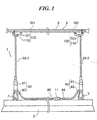
- Fig.1 is a drawing schematically showing an electrical apparatus suspension unit according to the one embodiment of the present invention.
- the electrical apparatus suspension unit 1 in this embodiment serves as power supplying to a lighting apparatus (a fluorescent lighting) 3 as well as suspending the lighting apparatus 3 from a ceiling 5.
- the suspension unit 1 is provided with two power supply wires 20-1 and 20-2, a lower holder 40 for securely connecting the lower end of the power supply wire 20 to a hung member 7 formed on the lighting apparatus 3 and a upper holder 100 for securely connecting the upper end of the power supply wire 20 to a rail 9 laid on the ceiling 5.
- the lighting apparatus 3 operates at a low voltage of AC600V or less.
- the structure of the power supply wire 20 will be explained.
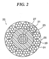
- Fig.2 is a cross-sectional drawing showing the structure of the power supply wire according to the present invention.
- the power supply wire 20 is composed of a core wire 21, an insulating layer 23 covering the core wire 21 and an outer layer 25 covering the insulating layer 23.
- the core wire 21 is made such that plural (for example, 19) strands (unit line) 27 made by copper alloy having high strength and high conductivity are stranded.
- the strand 27 has tensile strength of 500MPa or higher, preferably 700MPa or higher, more preferably 900MPa or higher and conductivity of 40%IACS or higher, preferably 50%ICAS or higher, more preferably 60%IACS or higher.
- a high strength and high conductive strand made of copper alloy having aforesaid property for example, a strand made of alloy of copper and silver, produced by Showa Electric Wire & Cable Co., Ltd., may be employed (refer to "Development of Cu-Ag alloy Ultra Fine wire with high strength and high conductivity" National Conference of Institute of Electrical Engineers of Japan, 1997).
- the strand is made such that an alloy having a structure in which a Cu-Ag eutectic phase exists around a copper group in a network state is subjected to a wire drawing in which a set of intermediate heat treatment and cold work treatment are repeated several times.
- the maximum conductivity it is possible to have the maximum tensile strength of 1000MPa and the maximum conductivity of 80%IACS.
- a soft copper wire for electricity has tensile strength of 250MPa and conductivity of 98%IACS.
- the strand has a diameter of 0.2mm, for example.
- the core wire 21 made by stranding nineteen of the strand 27 as described above has breaking strength of 54.8Kg and is allowed to pass current of 0.6SQ at a rated current of 6A (100V 600W).
- the core wire 21 has a diameter of 0.95mm.
- the insulating layer 23 covers outer circumference of the core wire 21 with a uniform thickness.
- the insulating layer 23 is made of nylon and has a thickness of 0.68mm, in this example.
- the outer layer 25 is made such that plural (for example, 12) stranded wires 31 are braided around the insulating layer 23.
- the stranded wire 31 is made such that plural (for example 7) strands 29 made of stainless steel are stranded.
- the strand 29 made of stainless steel has a diameter of 0.22mm.
- the power supply wire 20 having the outer layer 25 has a diameter of 3.6mm.
- the outer layer 25 made of stainless steel improves tensile strength, and therefore the power supply wire 20 allows breaking strength of 640kg.
- the suspension unit 1 employs the two power supply wires 20-1 and 20-2, as shown in Fig.1, in a manner such that the core wire 21 of the power supply wire 20-1 operates as a grounded conductor cable and the core wire 21 of another power supply wire 20-2 operates as a voltage-applied conductor cable.
- an induction current flows in the conduits of the conductor cables.
- the induction currents are canceled by the nonmagnetic and conductive outer layer 25, whereby heat generation of the insulating layer 23 being coated the wire core does not occur. Accordingly, the outer layer 25 works to enhance tensile strength of the wire as well as to cancel the induction current.
- Fig.3 is a drawing showing a structure of the lower holder.
- the lower holder (a wire grip with a hook) 40 is provided with a wire grip 41 capable of securely connecting the power supply wire 20 at a desirable position and a hook 43 which is engaged with the hung member 7 formed on the lighting apparatus 3.
- the hook 43 is connected to the bottom of the wire grip 41 at the upper portion thereof.
- Fig.4 is a drawing showing a structure of the wire grip
- Fig.4(A) is a side cross-sectional drawing
- Fig.4(B) is a plane cross-sectional drawing.
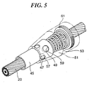
- Fig.5 is a partial perspective drawing showing a structure of the wire grip.
- the wire grip 41 securely connects the lighting apparatus 3, which is suspended by the hook 43 of the wire grip 41, to the power supply wire 20 at a desirable position (in other words, it is capable of adjusting a height of the lighting apparatus 3). Accordingly, the wire grip 41 requires sufficient strength to support a load of the lighting apparatus 3 while maintaining insulation of the core wire 21 of the power supply wire 20.
- the wire grip 41 is composed of an inner sleeve 45, plural balls 47 and 49, an outer sleeve 51 and a spring 53.
- the inner sleeve 45 has a wire-insertion bore 55 for inserting the power supply wire 20 therethrough.
- the wire-insertion bore 55 has a uniform inner diameter in the length direction (the longitudinal direction in Fig.4), which added ⁇ (for example, 1mm) to a diameter of the power supply wire 20.
- the inner sleeve 45 includes a cylindrical upper portion 45a and a conical lower portion 45b with a tapered outer surface 45c of which an outer diameter is widened toward the bottom of the inner sleeve 45.
- the conical lower portion 45b has two pairs of three ball-set bores 57 and 59 opened at both of the tapered outer surface 45c and the wire-insertion bore 55.
- each of the two pairs of the ball-set bores 57 and 59 extending in a perpendicular direction of the wire-insertion bore 55 (in a diametric direction) are arranged in two stages in the axis direction of the wire-insertion bore 55.
- the upper ball-set bores 57 have a diameter smaller than that of the lower ball-set bores 59.
- the upper and lower ball-set bores 57 and 59 are alternately arranged around an axis of the wire-insertion bore 55.
- the three upper ball-set bores 57 are arranged spaced by 120° around the axis
- the three lower ball-set bores 59 are arranged spaced by 120° around the axis while being sifted relative to the upper ball-set bores 57 by 60°. Accordingly, as shown in Fig.4(B), all of the ball-set bores are arranged spaced by 60° around the axis of the wire-insertion bore 55.
- each of the upper ball-set bores 57 a small-diameter ball 47 is received.
- a large-diameter ball 49 is received in each of the lower ball-set bores 59.
- Each of the upper ball-set bore 57 has a diameter added ⁇ (for example, 0.1mm) to the diameter of the ball 47 and a length slightly shorter than the diameter of the ball 47.
- Each of the lower ball-set bore 59 has a diameter added ⁇ (for example, 0.1mm) to the diameter of the ball 49 and a length slightly shorter than the diameter of the ball 49.
- each of the lengths means a length at the central portion of each ball-set bore 57, 59 in the width direction of the bores.
- the upper ball-set bores 57 have a diameter (a diameter of the small-diameter ball 47) of 2.4mm
- the lower ball-set bores 57 have a diameter (a diameter of the large-diameter ball 49) of 2.8mm.
- each of the bolls 47 and 49 are protruded partially into the wire-insertion bore 55 at the inside surface thereof.
- the conical lower portion 45b has a lower cylindrical portion 45d to which the spring 53 is fitted at the upper portion thereof.
- the outer sleeve 51 has a frustum-shaped upper portion 51a with a tapered inner surface 51c which is contacted with the tapered outer surface 45c of the inner sleeve 45, and a cylindrical lower portion 51b.
- the lower portion 51b is formed with a ring-shaped spring retainer 61 at the bottom of the inside thereof.
- the spring 53 is arranged in the outer sleeve 51 between the bottom surface of the conical lower portion 45b of the inner sleeve 45 and the spring retainer 61 of the outer sleeve 51.
- the spring 53 is fitted onto the lower cylindrical portion 45d of the inner sleeve 45 at the upper portion thereof.
- the spring 53 biases the inner sleeve 45 upwardly with respect to the outer sleeve 51 so that the tapered outer surface 45c of the inner sleeve 45 will contact with the tapered inner surface 51c of the outer sleeve 51.
- each of the balls 47 and 49 received in the ball-set bores 57 and 59 is pressed by the tapered inner surface 51c of the outer sleeve 51 at the outside surface thereof and protrudes into the wire-insertion bore 55 at the inside surface thereof.
- the wire 20 inserted through the wire-insertion bore 55 is pressed by the protruded balls 47 and 49 so as to be securely connected to the wire grip 40.
- the six balls will allow the total force for holding the wire applied by all of the balls to increase, while the force applied by each ball to decrease. This decreases the depth in which the balls are dug into the outer layer of the wire. As a result, since the depth of the balls dug into the insulating layer decreases, the insulation of the insulating layer is well maintained, whereby the core wire can be protected.
- the ball-set bores are arranged at the upper and lower stages in the axis direction of the wire-insertion bore, and the upper and lower ball-set bores are alternately arranged around an axis of the wire-insertion bore. This enables to have smaller space for arrangement of plural ball-set bores. And, since the force is applied to the wire by using plural balls from the equally separated positions around the wire, a load is not concentrated on one portion of the wire.
- Fig.6 is a drawing showing the releasing operation of the wire grip.
- a clearance D is produced between the outside surfaces of the ball-set bores 57 and 59 and the tapered inner surface 51c of the outer sleeve 51. Since the balls 47 and 49 are pressed inwardly by the tapered inner surface 51c of the outer sleeve 51, the clearance D permits the balls to move outwardly toward the clearance.
- the sliding action is permitted as long as the inner sleeve 45 being pressed with respect to the outer sleeve 51.
- the force by which the inner sleeve 45 is pressed is released.
- This causes the inner sleeve 45 to be biased by the spring 53, whereby the tapered outer surface 45c of the inner sleeve 45 is contacted with the tapered inner surface 51c of the outer sleeve 51.
- the balls 47 and 49 are pressed by the tapered inner surface 51c so as to hold the wire 20.
- the outer sleeve 21 is pulled downwardly by its own weight. This causes the tapered inner surface 51c of the outer sleeve 51 to be moved in the direction in which the inner diameter of the tapered outer surface 45c of the inner sleeve 45 becomes wide, as a result, the depth in which the balls 47 and 49 are dug into the wire 20 becomes deep, increasing a wire gripping force.
- Fig.7 is a cross-sectional drawing showing a shape of the ball-set bore.
- each of the ball-set bores 57 and 59 is not a straight through bore. As shown in the figure, each of the ball-set bores has a curved inner surface A at the inside end (the side of the wire-insertion bore 55). Each of the curved inner surfaces (a retainer portion) A has the same curvature as each of the bolls 47 and 49 received in each ball-set bore. Such inner surface A is machined by using a drill with a spherical distal end.
- the ball-set bores 57 and 59 having the aforesaid shape causes the balls 47 and 49 received therein to be retained by the curved inner surface A, whereby the balls do not protrude into the wire-insertion bore 55 excessively.
- the curved surface A has a suitable length which allows a gripping force of such degree that excessive load does not apply to the outer layer and the insulating layer.
- the thickness of the insulating layer can be kept constant, ensuring dielectric strength.
- the outer sleeve 51 is formed at the inner bottom thereof with a female thread 63 which is engaged with the upper portion of the hook 43. And, the spring retainer 61 is engaged deeply with the recess of the female thread 63.
- Fig.8 is a perspective drawing showing the hook.
- the hook 43 is composed of a wire holder 67 and suspension member 69.
- the wire holder 67 is formed at the upper portion thereof with a male thread to be engaged with the female thread 63 of the outer sleeve 51 of the wire grip 41, whereby the hook 43 is fixed to the wire grip 41.
- the wire holder 67 has a substantially cuboid-shape, and is formed with a slit 71 from the center of the upper end surface to approximately the center of the side surface (the right side surface in Fig.6).
- the slit 71 has the back surface which is sloped from the center of the upper end surface to the center of the side surface of the holder 67.
- the holder 67 has a thread bore 73 to be engaged with a screw 75, at the upper portion of the slit 71.
- two legs 77 are formed extending both sides of the slit 71.
- the legs 77 has thread bores 79 at the distal ends, into which a screw 81 is engaged.
- the suspension member 69 is mounted to the bridged screw 81 between the legs 77.
- the suspension member 69 has a loop-shape comprising a circular upper portion and a tear-drop shaped lower portion.
- the upper portion is hooked on the bridged screw 81 between the legs 77 of the wire holder 67.
- the lower portion is detachably attached to the hung member 7 (as shown in Fig.1) formed on the lighting apparatus 3.
- the suspension member 69 is composed of a C-shaped part 69a and a snap part 69b, and both are combined to form the loop-shape.
- the snap part 69b is pivotably connected to the upper end of the C-shaped part 69a, and is biased by a leaf spring (nor shown) so as to close the loop.
- a leaf spring not shown
- the snap part 69a is pivoted inwardly, the snap part 69a is separated from the C-shaped part 69b, resulting in opening a gap between the snap part 69a and the C-shaped part 69b, through which the hung member 7 of the lighting apparatus 4 is passed.
- the snap part 69b and the C-shaped part 69a are engaged such that the snap part 69b does not open outwardly and does not depart from the C-shaped part 69a.
- the wire 20 passing through the wire-insertion bore 55 and a spring retainer 61 of the wire grip 41 is inserted into the slit 71 from the upper end surface of the wire holder 67 and guided along the sloped back surface and then led out from the slit 71 at the side surface thereof. Accordingly, the wire 20 is straightly inserted in the wire grip 41 and laterally led out from the wire holder 67. Accordingly, it becomes possible that the wire 20 straightly hung from the ceiling is laterally turned through the lower holder 40 so as to be connected to a terminal 11 (as shown in Fig.1) of the lighting apparatus 3.
- a desirable length of the wire 20 is led out from the lower holder 40, and then the wire 20 is griped by the wire grip 41. Then, a screw 75 is engaged with the thread bores 73 of the wire holder 67 while catching the wire 20 between the distal end of the screw 75 and the back surface of the slit 71, and as the result, the wire 20 is securely held to the hook 43.
- the lighting apparatus 3 is securely held to the wire 20 by the lower holder (a grip with a hook) 40.
- the wire 20 led out from the lower holder 40 is connected to an AC socket of the terminal 11 mounted on the lighting apparatus 3, as shown in Fig.1.
- the wire 20 of which the outer layer is stripped is inserted to the socket, and the core wire 21 exposed by stripping the insulating layer is connected to a terminal contact.
- the distal end of the wire 20 is terminated with a terminal cap 85 (as shown in Fig.1).
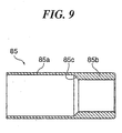
- Fig.9 is a cross-sectional drawing showing the terminal cap.
- the terminal cap 85 is a cylindrical member made of nickel plated brass, and has a large-diameter portion 85a and a small-diameter portion 85b.
- the large-diameter portion 85a has a diameter almost equal to the diameter of the wire 20
- the small-diameter portion 85b has a diameter almost equal to the diameter of the wire 20 of which the outer layer is stripped. Between the both portions, a tapered step 85c is formed.
- the wire 20 of which the outer layer is stripped is inserted into the large-diameter portion 85 of the terminal cap 85 until the stripped outer layer is enclosed by the large-diameter portion 85 and the end of the stripped outer layer is abutted on the tapered step 85c with the insulating layer being enclosed by the small-diameter portion 85b. Then, the cap 85 is fixed to the wire 20 by adhesion. Thus, the stripped outer layer is enclosed by the large-diameter portion 85a, thereby treating the distal end of the wire without loosing into the metal thin lines.
- the upper holder 100 is composed of a slide plug 101 attachable to the rail 9 and an electrode support 110 to which the upper end of the power supply wire 20 is connected.
- the rail 9 is a structure laid on the ceiling 5.
- the slide plug 101 is slidably mounted to the rail 9.
- the electrode support 110 is mounted on the under surface of the slide plug 101.
- Fig.10(A) is a drawing showing the electrode support and Fig.10(B) is a sectional drawing showing a body of the electrode support.
- the electrode support 110 which is made of nickel plated brass, connects the core wire 21 of the wire 20 to a conductor cable W inside the rail 9 and also grounds the outer layer 25 of the wire 20.
- the electrode support 110 is provided with a body 111, a large nut 113 and two small nuts 115.
- the body 111 has a wire-insertion bore 117 in the length direction.
- the body 111 as shown in Fig.10(B), has a large-thread portion 111a, a small-thread portion 111c and a flange portion 111b projected outwardly from between the large and small-thread portions 111a and 111c.
- the small-thread portion 111c has two slits 119 extending in the length direction (a longitudinal direction in Fig.10(B)) at the diametrical positions for each other.
- the large nut 113 is engaged with the large-thread portion 111a and each of the small nuts 115 is engaged with the small-thread portion 111c.
- the large-thread portion 111a thereof is inserted into a mounting opening 103 formed on the plug 101 from the upper side of the plug 101 until the flange portion 111b is locked on the plug 101.
- the large nut 113 is threadably engaged and tightened with the large-thread portion 111a from the lower side of the plug 101. This causes the plug 101 to be caught between the large nut 113 and the flange 111b, as the result, the body 111 of the electrode support 110 is securely mounted to the plug 101.
- the upper end of the wire 20 is inserted into the large-thread portion 111a of the wire-insertion bore 117 of the electrode support 110 and led out from the small-thread portion 111c thereof. Then, the outer layer of the led wire 20 is stripped and then divided into two bundles of thin lines. Each of the bundles is bended and caught in the slit 119 of the small-thread portion 111c, and then pressed toward the lower end of the slit 119 by using a driver. Then, the first small nut 115 is engaged and tightened with the small-thread portion 111c so as to catch and fix the bundles between the first small nut 115 and the flange portion 111b. This permits the outer layer 25 to conduct to the electrode support 110. In addition, the bundles of the outer layer 25 is cut off so as not to short with the plug 101.
- a pressure terminal 121 attached to the end of an earth cable 120 is inserted onto the small-thread portion 111c and then the second small nut 115 is engaged and tightened therewith so as to catch the pressure terminal 121 between the two small nuts 115. This permits the outer layer 25 to be grounded to the earth cable 120 via the electrode support 110.
- the wire 20 in which the insulating layer 23 is exposed by stripping the outer layer 25 is led to a terminal 105 inside the plug 101. Then, the exposed core wire 21 by stripping the insulating layer 23 conducts to the terminal 105. As shown in Fig.1, the core wire of one power supply wire 20-1 conducts to a grounded conductor cable W1 of a power line laid inside the rail 9 via the plug 101, and the core wire of another power supply wire 20-2 conducts to a voltage applied conductor cable W2 of the power line via the plug 101.
- the upper ends of the power supply wires 20 are connected to the plug 101 by using the electrode support 110. Then, the plug 101 is slid along the rail 9 to a desirable position. Next, the lower holder 40 is securely held to the wire by the wire grip 41 so as to suspend the lighting apparatus 3 at a predetermined height. At the same time, the wire holder 43 is hooked to the hung member 7 formed on the lighting apparatus 3. If the length of the wire 20 between the upper holder 40 and the terminal 11 is too long, the wire 20 therebetween is bundled on the lighting apparatus 3.
- the electrical apparatus suspension unit 1 serves as power supplying the lighting apparatus 3 as well as suspending it from the rail 9 or a wiring duct laid on the ceiling 5.
- the current flows through the core wire 21 of each power supply wire 20. Since the core wire 21 has a current power of 0.6SQ, sufficient electrical power enough for operating the lighting apparatus 3 can be supplied. Since the induction current generated on conducting the core wire 21 is canceled by the outer layer 25, heat generation is prevented, whereby it can be used in safety.
- the wire 20 has breaking strength of 640kg and the wires 20 are securely and safely connected to the lighting apparatus 3, it is possible to support the load of the lighting apparatus 3. According to the loading test (a withstand voltage test) using the power supply wire 20 and the lower holder 40, withstand voltage of 70kg/3000V is obtained. In addition, it is possible to adjust the height of the lighting apparatus by using the wire grip 41.
- Fig.11 is a drawing showing an electrical apparatus suspension unit according the second embodiment of the present invention.
- the electrical apparatus suspension unit 201 of the embodiment also suspends a lighting apparatus from the ceiling 5 by using the two power supply wires 20-1 and 20-2.
- a grounded conductor cable W1 and a voltage-applied conductor cable W2 are led out from an F-cable C and are connected to each of wiring terminals 13 mounted on the ceiling 5.
- the electrical apparatus suspension unit 201 has substantially the same structure as the device 1 as shown in Fig.1 except that an upper holder 210 has a structure for the structure of the wiring terminal 13.
- the upper holder 210 is composed of a plug 211 for the wiring terminal 13 and the electrode support 110 (as shown in Fig.10) having the same structure as that of the device 1 shown in Fig.1.
- the electrode support 110 is mounted to the plug 211.
- the plug 211 is mounted to the wiring terminal 13.
- the core wire of one power supply wire 20-1 conducts to the grounded conductor cable W1 at one wiring terminal 13 via the upper holder 210 and the core wire of another power supply wire 20-2 conducts to the voltage-applied conductor cable W2 at another wiring terminal 13 via the upper holder 210.
- Fig.12 is a drawing showing an electrical apparatus suspension unit according to the third embodiment of the present invention.
- the electrical apparatus suspension unit 301 of the embodiment suspends the lighting apparatus 3 from the ceiling 5 by using the two power supply wires 20-1 and 20-2.
- the rail 5 is not laid on the ceiling 5, and the lighting apparatus 3 has a terminal (a pressure joint terminal) 17 inside thereof.
- a grounded conductor cable W1 and a voltage-applied conductor cable W2 led from a F-cable C are connected to the wiring terminal 15 above the ceiling.
- the wires 20 are maintained to the ceiling 5 by the upper holder 310 at the upper portions thereof.
- Fig.13 is a drawing showing a structure of the upper holder.
- the upper holder (a wire grip with a holding part) 310 is composed of a wire grip 41 capable of being connected to the power supply wire at a desirable position and a mounting part 311 for mounting the wire grip 41 to the ceiling (a structure).
- the wire grip 41 has the same structure as that of the wire grip 41 of the device 1 shown in Fig.1, and is composed of an inner sleeve, balls, an outer sleeve and a spring, so, the description of each part of the wire grip 41 is omitted. In this example, the wire grip 41 is used upside down.
- the mounting part 311 has a sleeve portion 313 and a flange portion 315 projected outwardly from the lower end of the sleeve portion 313. And, the mounting part 311 has a wire-insertion bore 317 on the axis of the wire-insertion bore 55 of the wire grip 41 with the same diameter as the diameter of the wire-insertion bore 55.
- the sleeve portion 313 is formed at the lower end thereof with a male thread, which is engaged with the female thread 63 (as shown in Fig.4(A)) of the outer sleeve 51 of the wire grip 41 so as to couple the mounting part 311 to the wire grip 41.
- the sleeve portion 313 thereof is inserted in a mounting opening of the ceiling 5 until the sleeve portion 313 thereof is protruded over the ceiling and the flange portion 313 is abutted on the ceiling 5.
- the flange portion 315 is fixed to the ceiling 5 by screws 319 and nuts 321.
- the wire 20 is inserted upwardly through the wire-insertion bores 55 and 317.
- the wire 20 led out from the upper holder 310 is connected to the wiring terminal 15 above the ceiling.
- the wire core of one power supply wire 20-1 conducts to the grounded conductor cable W1 and the core wire of another power supply wire 20-2 conducts to the voltage-applied conductor cable W2.
- an earth attachment 350 is mounted to the power supply wire 20-2 conducted to the voltage-applied conductor cable W2 so as to ground the outer layer of the power supply wire 20-2.
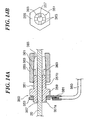
- Fig.14 is a drawing showing a structure of the earth terminal
- Fig.14(A) is a side cross-sectional drawing
- Fig.14(B) is a front drawing.
- the earth attachment 350 made of nickel plated brass is composed of a body 351, a nut 353 for holding an earth terminal, and a nut 355 for fastening the wire 20 thereto.
- the body 351 has a wire-insertion bore 357 in the length direction. And, the body 351 is formed with a flange 359 projecting outwardly at the one end side (the left side in the figure). The flange 359 is positioned between an earth terminal mounting portion 351a (the left side of Fig.14(A)) and a wire fastening portion 351b (the right side of Fig.14(A)).
- the earth terminal mounting portion 351a is formed with a thread at the outer surface for engagement with the nut 353.
- a pressure terminal 381 attached to the distal end of the earth cable 380 is fitted onto the earth terminal mounting portion 351a and then the nut 353 is engaged and tightened with the earth terminal mounting portion 351a so that the pressure terminal 381 can be positioned between the nut 353 and the flange 359, resulting in that the attachment 350 is grounded via the pressure terminal 381.
- the wire fastening portion 351b has a thread outer surface which is about half the length of the body 351 on the flange side and a tapered outer surface 361 which is tapered toward the end of the body. Between the thread and the tapered outer surface 361, four radial slotted grooves 363 are formed.
- the nut 355 is cylindrical-shaped and has an inner surface with a thread which is about half the length thereof and a tapered surface 365. The thread of the nut 355 is engaged with the thread of the fastening portion 351b.
- the nut 355 After inserting the wire 20 through the wire-insertion bore 357 of the body, the nut 355 is engaged and tightened with the thread of fastening portion 351b. As the result, the tapered inner surface 365 of the nut 355 presses the tapered outer surface 361 of the body inwardly, whereby a part from the slotted groove 363 to the end of the body (the right side part of the figure) is pressed inwardly so as to fasten the wire 20 inserted through the wire-insertion bore 357, and therefore the earth attachment 350 is conducted and securely maintained to the wire 20.
- the power supply wire 20 can be grounded in the intermediate portion of the outer surface thereof via the earth attachment 350 and the earth cable 380.
- the lower holder will be explained.
- the lighting apparatus 3 since the lighting apparatus 3 has the terminal 17 (a pressure joint terminal) placed inside thereof, it is necessary to lead out the lower ends of the wires 20 to the inside of the lighting apparatus 3. Accordingly, by using the electrode support 110 (as shown in Fig.10) of the electrical apparatus suspension unit as shown in Fig.1, the lower portion of the wire 20 is securely held to the lighting apparatus 3 while conducting the core wires of the wire 20 to the pressure joint terminal 17. In this embodiment, the electrode support 110 is used upside down.
- the large-thread portion 111a thereof is inserted through a mounting opening of the lighting apparatus 3 from the under side of the lighting apparatus 3 (as shown in Fig.10) until the electrode support 110 is locked to the lighting apparatus 3 at the flange 111b thereof. Then, the large nut 113 is engaged with the large-thread portion 111a from the upper side of the lighting apparatus 3 so as to securely hold a casing of the lighting apparatus 3 between the large nut 113 and the flange 111b.
- the outer layer of the wire 20 is grounded to the earth cable 120 by the electrode support 110 inside of the lighting apparatus 3. Then, the wire 20 in which the insulating layer is exposed by stripping the outer layer is led to the pressure joint terminal 17 inside of the lighting apparatus 3, and after stripping the insulating layer, the exposed core wires conduct to the pressure joint terminal 17.
- Fig.15 is a drawing showing a structure of an electrical apparatus suspension unit according to the forth embodiment of the present invention.
- the electrical apparatus suspension unit 401 serves as suspending the lighting apparatus 3 from the ceiling 5 as well as power supplying thereto.
- the lighting apparatus 3 is suspended by one power supply wire 420.
- the lighting apparatus 3 has an electrical power of AC100V (100V, 200W).
- the electrical apparatus suspension unit 401 is provided with one power supply wire 420 and an upper holder 440 for connecting the upper end of the wire 420 to a wiring terminal 13.
- the wire 420 has a predetermined length.
- the structure of the power supply wire 420 will be explained.
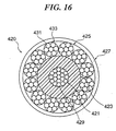
- Fig.16 is a cross-sectional drawing showing the power supply wire.
- the power supply wire 420 comprises a core wire 421, an insulating layer 423 covering the core wire 421, an outer layer 425 covering the insulating layer 423 and an outermost insulating layer 427 covering the outer layer 425.
- the core wire 421 is made such that plural strands 429 made of copper alloy having high strength and high conductivity are stranded.
- a strand made of alloy of copper and silver produced by Showa Electric Wire & Cable Co., Ltd. may be used, as same for the electrical apparatus suspension unit of the Fig.1.
- the core wire 421 is made such that plural (for example, 19) strands 429 are stranded.
- the core wire 421 has cutting resistant strength of 54.8kg and current of 0.6SQ at a rated current of 6A (100V600W).
- the insulating layer 423 made of nylon covers the core wire 421 with a constant thickness.
- the outer layer 425 is made such that plural (for example, 12) stranded wires 433 are braided around the insulating layer 423.
- the stranded wire 433 is made such that plural (for example, 7) copper wires 431 are stranded.
- the copper wire 431 may be made of copper alloy having high strength and high conductivity same as the core wire 421.
- the outermost insulating layer 427 covers the outer layer 425 with a constant thickness.
- an insulating tube made of tefron (trade mark) having a thickness of 0.4mm may be used as the outermost insulating layer 427.
- the power supply wire 420 In such type of the power supply wire 420, a current flows through both of the core wire 421 and the outer layer 425. And, one of the core wire 421 and the outer layer 425 serves as a voltage-applied conductor cable and another thereof serves as a grounded conductor cable. Since an induction current generated in conducting the core wire 421 is canceled by an induction current generated in conducting the outer layer 425, heat generation both in the insulating layer 423 and the outermost insulating layer 427 is prevented, whereby it can be used in safety.
- the power supply wire 420 has cutting resistant strength of 300Kg. In this embodiment, although the outer layer 425, made of copper apply having high strength and high conductivity, has cutting resistant strength smaller than that made of stainless steel, there is no problem in the practical use.
- the power supply wire 420 is divided into a wire core terminal and an outer layer terminal at the lower end. Each of the terminals is connected to the terminal 11 of the lighting apparatus 3. And, the power supply wire 420 is divided into a wire core terminal and an outer layer terminal at the upper end. Each of the terminals is connected to a plug 440, which is mounted the wiring terminal 13 fixed on the ceiling.
- a single power supply wire allows suspending the lighting apparatus and also supplying power thereto. Accordingly, such the wire can be used for various applications such as a pendant light as shown in the figure.
- Fig.17 is a drawing showing a structure of an electrical apparatus suspension unit according to the fifth embodiment of the present invention.
- the electrical apparatus suspension unit 501 suspends a lighting apparatus 3 from the ceiling by one power supply wire, similar to the unit of the Fig.15.
- the lighting apparatus 3 operates at low-volt (36V or lower, AC or DC) and has a working power of 12V60W or lower than the apparatus of Fig.15.
- a wiring terminal is not mounted on the ceiling, it is necessary to connect the upper end of the wire to a wiring terminal above the ceiling.
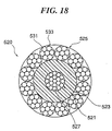
- Fig.18 is a cross-sectional drawing showing the power supply wire of the lighting apparatus suspension unit.
- the power supply wire 520 comprises a core wire 521, an insulating layer 523 covering the core wire 521 and an outer layer 525 covering the insulating layer 523.
- the power supply wire 520 has a structure in which the outermost insulating layer 427 is removed from the power supply wire 420 (as shown in Fig.16) of the device of Fig.15.
- the core wire 521 is made such that plural strands 527 made of copper alloy having high strength and high conductivity are stranded.
- a strand made of alloy of copper and silver produced by Showa Electric Wire & Cable Co., Ltd. may be used, as same for the electrical apparatus suspension unit of the Fig.1.
- the core wire 521 is made such that plural (for example, 19) the strands 527 are stranded.
- the core wire 521 has cutting resistant strength of 54.8kg and current of 0.6SQ at a rated current of 6A (100V600W).
- the insulating layer 523 made of nylon insulant covers the core wire 521 with a constant thickness.
- the outer layer 525 is made such that plural (for example, 12) stranded wires 533 are braided around the insulating layer 523.
- the stranded wire 533 is made such that plural (for example, 7) thin lines 531 made of stainless steel are stranded.
- the thin line 531 is made of the copper alloy having high strength and high conductivity same as the core wire 521.
- a current flows through the core wire 521 and the outer later 525. That is, one of the core wire 521 and the outer layer 525 serves as a voltage-applied conductor cable and another thereof serves as a grounded conductor cable. In the embodiment, a current flows through the outer layer 525 which is an outermost surface of the wire 520. However, since the lighting apparatus 3 of the embodiment operates at low voltage and therefore intensity of the current flowed through the outer layer 525 is small, there is very low possibility of the electric shock even if someone directly touches the wire 20.
- the wire grip 310 (as shown in Fig.13) is used.
- the wire 520 is mounted to the ceiling by using the upper holder.
- either one of the core wire 521 or the outer layer 525 serves as a grounded conductor cable and another thereof serves as a voltage-applied conductor cable.
- the earth attachment 350 (as shown in Fig.14) can be used in order to conduct the outer layer 525 directly to the wiring terminal.
- the earth attachment 350 allows the outer layer 525 to conduct not to an earth cable but to a conductor cable 380. And then, the conductor cable 380 may be connected to the wiring terminal.
- Fig.19 is a drawing showing a structure of an electrical apparatus suspension unit according to the sixth embodiment of the present invention.
- the electrical apparatus suspension unit 501 is available for suspension of a comparatively heavy lighting apparatus 3 such as a chandelier operated at an electrical power of 300W.
- the electrical apparatus suspension unit 601 employs a reinforcing wire 610 in addition to two power supply wires 20-1 and 20-2.
- the two power supply wires 20 have the same structure of the power supply wire 20 (as shown in Fig.2) of the unit of Fig.1.
- Each of the lower ends of the wires 20 is held to the lighting apparatus 3 by using the electrode support 110 (as shown in Fig.10).
- each of the upper ends thereof is held to the ceiling 5 by the wire grip 310 (as shown in Fig.13).
- the reinforcing wire 610 having the same appearance as the wire 20 is made of stainless steel. Both ends of the reinforcing wire 610 are held to the lighting apparatus 3 and the ceiling 5 by using the electrode support 110 and the wire grip 310.
- an additional reinforcing wire allows obtaining enough withstand load.
- more reinforcing wires may be used.
- Fig.20 is a drawing showing a structure of an electrical apparatus suspension unit according to the seventh embodiment of the present invention.
- the electrical apparatus suspension unit 701 of this example connects plural lamps 3 serially between side walls S1 and S2.
- the unit 701 has plural power supply wires 720.
- the power supply wire 720 the power supply wire (as shown in Fig.16 and Fig.18) in which the core wire and outer layer serves as a conductor cable can be used.
- the power supply wire 520 (as shown in Fig.18) which does not have the outermost layer can be used.
- the power supply wire 420 (as shown in Fig.16) which has the outermost layer can be used.
- the wire 720 is held to the lamp 3 using the electrode support 110 (as shown in Fig.10).
- the wire 720 is led out from the electrode support 110 to inside of the lamp 3, and the core wire and the outer layer of the wire 720 are connected to the terminal 11 respectively inside the lamp 3.
- the wire 720 is held to the side walls S1 and S2 by using the wire grip 310 (as shown in Fig.13) and the electrode support 110 (as shown in Fig.10).
- the wire 720 is held to the side wall S1 by using the electrode support 110, both of the core wire and the outer layer which are divided through the electrode support 110 are connected to the terminal 15 connected to a F-cable C.
- the outer layer is connected to the earth cable 120 by using the electrode support 110 shown in Fig.10, in this embodiment, the outer layer may be connected to a conductor cable which is connected to the terminal 15.
- the lamp 3 may conduct through the wire grip 310 mounted on the side wall S2.
- Fig.21 is a drawing showing an electrical apparatus suspension unit according to the eighth embodiment of the present invention.
- the electrical apparatus suspension unit 701' has the same structure as the electrical apparatus suspension unit 701 of Fig.19 except that plural lamps 3 are connected serially between the ceiling S1 and a floor S2.
- Fig.22 is a drawing showing an electrical apparatus suspension unit according to the ninth embodiment of the present invention.
- This type of the electrical apparatus suspension unit 901 is available for a suspension of an electrical apparatus 910 such as a thin type liquid crystal television and a sign display.
- the electrical suspension unit 901 allows to suspend a heavy and flat electrical apparatus by using two power supply wires 20.
- the power supply wire 20 (as shown in Fig.2) of the electrical apparatus suspension unit of Fig.1 can be used.
- the lower ends of the wires 20 are held to the electrical apparatus 910 by using the wire grips 40 (as shown in Fig.3 and Fig.4).
- a rail 18 with an attachment 19 slidable along the rail 18 is laid on a ceiling, it is possible to adjust a wire suspension position in the lateral direction.
- the rail 18 is installed between both side walls under the ceiling.
- the attachment 19 is attached so as to slide along the rail 18.
- the upper ends of the wires 20 are securely held to the attachments 19 by using the wire grips 310 (as shown in Fig.13). And, the wires 20 are led out from the attachment 19 upwardly, after through mounting openings of the ceiling 5, and connected to the terminal 15 connected to the F-cable C.
- a power supply wire three kinds of wire (as shown in Fig.2, Fig.16 and Fig.18) can be used, and as a wire holder, the wire grip 40 (as shown in Fig.3), the electrode support 110 (as shown in Fig.10) and the wire grip 310 (as shown in Fig.13) can be used. And, in order to conduct the power supply wire, the earth attachment 350 (as shown in Fig.14) and the electrode support 110 can be used. By selecting an appropriate power supply wire, wire holder and the like among these, it is possible to suspend an electrical apparatus such as a lighting apparatus in various forms.
- This embodiment shows a method for connecting the lower end of a power supply wire to an electrical apparatus (a lighting apparatus) and conducting a conductor cable of the power supply wire to a terminal of the electrical apparatus by using a lower holder (a wire grip with a hook).
- the power supply wire has substantially the same structure of the power supply wire 20 of Fig.2 and comprises a core wire composed of stranded wire made of copper alloy having high strength and high conductivity, and an insulating layer covering the core wire and an outer layer covering the insulating layer.
- the outer layer is composed of a braided wire such that a bundle of longitudinal strands and a bundle of transverse strands, which are made of nonmagnetic metal, are braided. Since such braided wire has contractility, it is slidable in the length direction of the wire.
- the power supply wire itself is flexible.
- the lower holder is composed of a wire grip capable of being connected to the power supply wire at a desirable position and a hook (represented by 43 in Fig.3) which is hooked to the hook formed on the lighting apparatus.
- the description of the hook is omitted.
- Fig.23 is a drawing showing a whole shape of the wire grip
- Fig.23(A) is a front drawing
- Fig.23(B) is a left side drawing
- Fig.23(C) is a plane drawing.
- the wire grip 1001 is provided with a jig 1101 for inserting and connecting the power supply wire to the wire grip.
- the jig 1001 has an outer surface correspondent with the outer surface of the wire grip 1001.
- the wire grip 1001 will be explained.
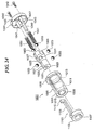
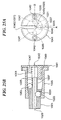
- Fig.24 is a drawing showing a structure of the wire grip.
- Fig.25 is a drawing showing a part of the wire grip
- Fig.25(A) is a side drawing
- Fig.25(B) is a cross-sectional drawing crossed by A-B.
- the wire grip 1001 is provide with an outer sleeve 1005, an inner sleeve 1021, plural balls 1033, a spring 1051 and a spring retainer 1041 and has almost the same function of the wire grip 41 of the Fig.5.
- the outer sleeve 1005 has a cylindrical portion 1007 and a flange portion 1008, and has an inner sleeve insertion bore 1009 on the central axis thereof.
- the inner sleeve insertion bore 1009 has a tapered inner surface 1011 which is tapered toward the end thereof and a cylindrical inner surface 1013.
- the outer sleeve 1005 is formed with a slotted groove 1015 communicated the outer surface of the outer sleeve 1005 with the inner sleeve insertion bore 1009.
- the slotted groove 1015 extends in the full length of the outer sleeve 1005.
- the inner sleeve 1021 is inserted in the inner sleeve insertion bore 1009 of the outer sleeve 1005, and has a small-diameter cylindrical portion 1023, a large-diameter cylindrical portion 1027 and a tapered portion 1025 which is tapered from the outer-diameter portion 1029 to the small-diameter portion 1023.
- the inner sleeve 1021 has a wire-insertion bore 1029 for inserting the wire therethrough on the central axis thereof.
- the inner sleeve 1021 is formed with a slotted groove 1031 communicated the outer surface thereof with the wire-insertion bore 1029.
- the slotted groove 1021 extends in the full length of the inner sleeve 1021.
- the tapered portion 1021 is formed with three ball-set bores 1031 extending in a perpendicular direction of the wire-insertion bore 1029 (in a diametric direction) between the tapered outer surface and the wire-insertion bore 1029.
- the ball-set bores 1031 are arranged at spaced positions (120°) around the axis of the wire-insertion bore 1029. In each of the ball-set bores 1031, a ball 1031 is received.
- the balls 1031 are made of electrical insulating material (for example, hard plastic (engineer plastic such as nylon and delrin) and ceramics (for example, alumina)).
- Each of the ball-set bore 1031 has a diameter added ⁇ (for example, 0.1mm) to the diameter of the ball 1033 and a length slightly shorter than the diameter of the ball 1033. Accordingly, when each of the balls 1033 is received in each of the ball-set bores 1031, each of the bolls 1033 is protruded to the wire-insertion bore 1029.
- ⁇ for example, 0.1mm
- the large-diameter cylindrical portion 1027 is formed with two spring receiving grooves 1035 and a guide groove 1037 (as shown in Fig.25). As described later, in each of the spring receiving grooves 1035, the spring which biases the inner sleeve 1021 in the axis direction of the wire-insertion bore 1029 is received. And, in the guide groove 1037, a straight shank for guiding the inner sleeve 1021 straightforward is received. Each of the spring receiving grooves 1035 and the guide groove 1037 extend from the end surface of the large-diameter portion 1027 in the length direction of the inner sleeve 1021.
- each of the spring receiving grooves 1035 are arranged on both side of the slotted groove 1031 at a central angle of 90° around the axis of the inner sleeve.
- the guide groove 1037 is arranged on the opposite side of the slotted groove 1031 at a central angle of 180° around the axis of the inner sleeve.
- the spring receiving grooves 1035 have a length slightly shorter than that of the guide groove 1037.
- each of the grooves has a semispherical bottom surface.
- the spring receiving groove 1035 has a semispherical upper end surface.
- the spring retainer 1041 has a wire-insertion bore 1043 at the central thereof.
- the spring retainer 1041 is formed with a slotted groove 1045 from the outer surface thereof to the wire-insertion bore 1043.
- the spring retainer 1041 is formed on the inner surface (the surface on the side of the outer sleeve) with two spring supporting pins 1047 and a straight shank 1049 extending in the length direction.
- a spring 1051 is inserted onto each of the spring receiving pins 1047, and a ball 1053 is received on the upper end of each spring 1051.
- the spring receiving pins 1047 have a length slightly shorter than that of the straight shank 1049.
- the spring receiving pins 1047 are arranged on both side of the slotted groove 1045 at a central angle of 90° around the axis of the spring retainer 1041.
- the straight shank 1049 is arranged on the opposite side of the slotted groove 1045 at a central angle of 180° around the axis of the spring retainer 1041.
- each of the spring receiving pins 1047 is positioned in the spring receiving groove 1035, and the straight shank 1049 is positioned in the guide groove 1037.
- the spring retainer (a cap) 1041 is fixed to the flange portion 1008 of the outer sleeve 1005 by screws 1042 so that the slotted groove 1045 of the spring retainer 1041 is aligned with the slotted groove 1015 of the outer sleeve 1005 around the axis thereof.
- the slotted grooves 1045 of the spring retainer 1041 is communicated with both of the slotted grooves 1031 and 1015 of the inner sleeve 1021 and the outer sleeve 1005, respectively, each other.
- the communicated slotted grooves are formed between the outer surface of the wire grip 1001 and the wire-insertion bore 1029.
- the inner sleeve 1021 is forced straightforward along the straight shank 1049, resulting in that the tapered surface 1025 of the inner sleeve 1021 is contacted with the tapered inner surface 1011 of the outer sleeve 1005.
- the balls 1033 received in the ball-set bores 1031 of the inner sleeve 1021 are pressed by the tapered inner surface 1011 of the outer sleeve 1005 at the outside surface thereof, whereby the inside surfaces of the balls 1033 are protruded in the wire-insertion bore 1029.
- This causes the outer layer of the power supply wire inserted through the wire-insertion bore 1029 to be pressed by the balls 1033, enabling the wire to be held by the wire grip 1001.
- the balls 1033 are caught on meshes of the braided wire of the outer layer of the wire and also tension applied the mashes causes the meshes to be contracted radially, resulting in increasing the gripping force.
- the inner sleeve 1021 In order to release the wire from the wire grip 1001, the inner sleeve 1021 is pressed toward the spring retainer 1041 against the biasing force of the spring 1051. This causes the tapered outer surface 1025 of the inner sleeve 45 to be moved backwardly from the state in which the tapered outer surface 1025 is contacted to the tapered inner surface 1011 of the outer sleeve 1005. As a result, a clearance is left between the tapered inner surface 1011 of the outer sleeve 1005 and the tapered outer surface 1025 of the inner sleeve 1021, in other word, outside of the tapered outer surface 1025 of the inner sleeve 1021. This enables the balls 1033 received in the ball-set bores 1031 to move outwardly, resulting in that the force by which the wire 20 is gripped disappears or becomes weak. Then, the wire 20 can freely slide upwardly and downwardly.
- the balls 1033 of the wire grip 1001 are made of electrical insulating material, even if the balls 1033 will be bite into the insulating layer between the meshes of the outer layer, insulation performance of the core wire of the wire can be maintained.
- the wire When the power supply wire would have a certain degree of rigidly, the wire can be inserted through the wire-insertion bore 1029 of the wire grip 1001 with the end in the lead.
- the power supply wire made of a braided wire would be inserted through the wire-insertion bore 1029 with the end in the lead, it is necessary to use a wire which has a predetermined length and is terminated with a cap. Accordingly, when the power supply wire with the outer layer made of a braided wire is held to the wire grip, the terminating treatment after cutting off the wire at the predetermined length is required. Therefore, if changing the length of the wire during installation work is necessary, in a case in which the height of the installation location goes wrong, inconveniences happen.
- the wire grip 1001 the wire is pushed into the wire-insertion bores 1029 and 1043 through the slotted grooves 1015, 1031 and 1045 at the intermediate portion of the wire by using a jig 1101.
- Fig. 26 is a drawing showing a structure of the jig
- Fig.26(A) is a front drawing
- Fig.26(B) is a bottom plane drawing
- Fig.26(C) is a side drawing.
- the jig 1101 works such that the inner sleeve 1021 is pressed toward the outer sleeve 1005 so as to communicate the wire-insertion bore 1029 with the outer surface of the wire grip and also the wire is pushed into the wire-insertion bore 1029.
- the jig 1101 has a ring-shaped portion (a ring portion) 1103 for pressing the inner sleeve 1021 in an opposed direction to the biasing direction of the spring 1051 and a strip portion 1105 extending the ring portion for pushing the wire into the wire-insertion bore through the slotted grooves.
- the ring portion 1103 has an inner surface and an outer surface.
- the ring portion 1103 has an outer diameter equal to the outer diameter of the cylindrical portion 1007 of the outer sleeve 1005 and an inner diameter equal to the outer diameter of the small-diameter portion 1023 of the inner sleeve 1021.
- the ring portion 1103 is formed with a wire-insertion slit 1107 between the outer and inner surfaces.
- the wire-insertion slit 1107 has a width wider than the diameter of the wire.
- the strip portion 1105 has a proximal section 1109 projecting inwardly from the inner surface of the ring portion 1103 and a body section 1111 extending from the end surfaces of the ring portion 1103 and the proximal section 1109 perpendicular to the ring portion 1103. That is, as shown in Fig.26(C), in side view, the proximal section 1109 and the body section 1111 project in the radial direction of the ring portion 1103.
- the body section 1111 has a length equal to the length of the slotted groove 1015 of the outer sleeve 1005.
- the strip portion 1105 has a width equal to the width of the slotted groove 1015.
- the proximal portion 1109 has cross section of rectangle.
- the body section 1111 has an outside portion 1111a of a square cross-sectional shape and an inside portion 1111b of a tapered cross-sectional shape.
- the ring portion 1103 is formed with a hook 1113 to which a string for tethering the jig 1101 to the wire grip is connected, as described later.
- the strip portion 1105 is formed with a projection 1115 at the tip thereof.
- Fig.27 and Fig.28 are front cross-sectional drawings showing the handling method of the jig.
- the intermediate portion of the wire W is fitted into the slotted grooves 1015, 1031 and 1045 of the wire grip 1001 until the wire W is contacted to the balls 1033 protruded into the wire-insertion bore 1029.
- the jig 1101 is positioned such that the ring portion 1103 is placed on the side of the inner sleeve 1021, and the wire W is passed into the ring portion 1103 through the wire-insertion slit 1107.
- the strip portion 1105 is positioned on the slotted grooves 1015 and 1031.
- the wire W is contacted to the balls 1033, the strip portion 1105 is contacted to the wire W and therefore is not completely fitted into the slotted grooves. So, as shown in the figure, the jig 1101 is slanted with respect to the wire grip 1001.
- the ring portion 1103 is fitted onto the lower portion of the inner sleeve 1021, and the strip portion 1105 extends obliquely from the ring portion such that the body section 1111 is partially fitted into the slotted groove 1015 of the inner sleeve 1021 and contacted to the wire W in the slotted groove 1015.
- the ring portion 1103 of the jig 1101 is pressed toward the wire grip 1001.
- This causes the inner sleeve 1021 to be pressed with respect to the outer sleeve 1005, causing the balls 1033 to be moved outwardly in the inner sleeve.
- Further pressing the ring portion 1103 toward the wire grip 1001 causes the wire W to be pushed by the strip portion 1105 and fitted into the wire-insertion bore 1029 through the slotted groove 1015.
- Fig.28(A) when the jig 1101 is pressed until the ring portion 1103 is contacted on the outer sleeve 1005, the jig 1101 turns clockwise in the figure.
- the ring portion 1103 is perfectly fitted onto the small-diameter portion 1023 of the inner sleeve 1021 and the strip portion 1105 pushes the wire W into the wire-insertion bore 1029.
- the wire W can be perfectly inserted into the wire-insertion bore 1029 by pressing the strip portion 1105 because the strip portion 1105 has the tapered inside portion 1111b capable of fitting into between the balls 1033.
- the inner sleeve 1021 is biased by the spring 1051, and as the result, the balls 1033 are protruded into the wire-insertion bore 1029, gripping the meshes of the outer layer of the wire W. This enables the wire W to be securely held to the wire grip 1001.
- the jig 1101 since the jig 1101 has the same outer shape as the wire grip 1001, it is possible to maintain the jig 1101 fitted into the slotted grooves of the wire grip 1001. In this case, as described later, the jig 1101 is tethered to the wire grip 1101 or a surrounding member by using a string connected to the hook 1113 of the jig 1101.
- Fig.29 is a drawing showing a structure of the jig according to another embodiment.
- the jig 1201 in the embodiment has the same structure as the jig of Fig.26 and has a ring portion 1203 and a strip portion 1205 except that the strip portion 1205 does not have a projection (represented by 1115 in Fig.26).
- the strip portion 1205 has a rounded inner end 1205a. This allows smooth sliding of the strip portion 1205 with respect to the wire.
- Fig.30 is a drawing showing a state in which the wire grip is attached to the electrical apparatus.
- the wire W is held to the base B of the lighting apparatus by using the wire grip 1001.
- the outer sleeve and the spring retainer have a flattened side surface in the length direction, as shown in Fig.30(A).
- the lighting apparatus has the base B with a mounting opening through which a pipe 1301 is inserted.
- a L-shaped bracket 1305 is fixed to the pipe 1301 protruded over the base B via a washer 1303.
- the wire grip 1001 is mounted to the L-shaped bracket 1305 by screws 1307 such that the flattened side surface is abutted on the bracket 1305 with keeping the spring retainer 1041 down.
- the jig 1101 is tethered to the bracket 1305 by a string 1150.
- the jig 1101 keeps being connected to the wire grip 1001 even after the wire W is held to the grip 1001.
- the jig 1101 may be also used when a suspension length of the wire is changed, in addition to when the wire is held to the grip. Accordingly, it is preferable that the jig is always prepared beside the grip. So, the jig 1101 is tethered to the bracket 1305 by using the string 1150, whereby the jig 1101 would not be lost, and it would not be necessary to prepare the jig again when the wire would be detached from the wire grip or the suspension length of the wire would be changed.
- the wire grip 1001 is held to the wire W suspended from the ceiling at a desired position (a desired height of the lighting apparatus) in a such manner as described above. Then, the wire grip 1001 is fixed to the bracket mounted to the base of the lighting apparatus. And, the wire W inserted into the wire-insertion bore of the wire grip 1001 is led therefrom, and after inserting through the pipe 1301, it is led to the terminal inside the lighting apparatus and cut off. Then, the wire W is treated such that the outer layer thereof is slid in the length direction so as to expose the insulating layer. And, the insulating layer is stripped by using a nipper so as to expose the core wire to which the terminal of the conductor cable is connected.
- Fig.31 is a drawing showing a state in which wire grip according to another embodiment is attached.
- the wire grip 1501 in the embodiment has the same structure and function as the aforesaid wire grip 1001 except for the shape of the outer sleeve.
- the outer sleeve 1503, as shown in the figure, has a columned shape with a central axis thereof perpendicular to the axis of the wire-insertion groove 1505.
- Such shape of the outer sleeve enables to attach another member to the circular side surfaces of the outer sleeve easily. Accordingly, for example, when a shelf will be held at the intermediate portion of the power supply wire, after connecting the wire grip 1501 to the intermediate portion of the wire, an attachment for the shelf is mounted to the circular side surface of the outer sleeve by using a mounting member.
- the lighting apparatus has a base B with a mounting opening O through which a pipe 1531 is inserted.
- a bracket 1535 is fixed to the pipe 1531 protruded over the base B via a washer 1533.
- the bracket 1535 has a horseshoe shape comprising a bottom wall and side walls perpendicular to the bottom wall.
- the bracket 1535 is fixed to the pipe 1531 at the bottom wall.
- the wire grip 1501 is placed between the side walls of the bracket 1535 and fixed thereto at the side surface thereof.
- the wire W may be led laterally from the wire-insertion bore 1505 over the base B without inserting through the pipe 1531.
- the jig 1511 is tethered to the bracket 1501 by a string 1521.
- the present invention can provide a power supply wire capable of serving as power-supplying and also suspending an electrical apparatus with having high tensile strength.
- the power supply wire and a grip for connecting an electrical apparatus to the wire enables to provide an electrical apparatus suspension unit capable of suspending a heavy electrical apparatus such as a lighting apparatus, a liquid crystal display, a speaker and a microphone.
Landscapes
- Engineering & Computer Science (AREA)
- General Engineering & Computer Science (AREA)
- Mechanical Engineering (AREA)
- Architecture (AREA)
- Civil Engineering (AREA)
- Structural Engineering (AREA)
- Installation Of Indoor Wiring (AREA)
- Cable Accessories (AREA)
- Insulated Conductors (AREA)
- Processing Of Terminals (AREA)
Abstract
The electrical apparatus suspension unit 1 is
provided with two power supply wires 20-1 and 20-2 by
which the electrical apparatus 3 is conducted and
suspended from the ceiling 5. Each of the wires 20 is
connected to the hung member of the electrical apparatus
3 at the lower end by the a lower holder 40, and
connected to the rail 9 laid on the ceiling 5 at the
upper end by an upper holder 100. The power supply wire
20 comprises a core wire 21, an insulating layer 23
covering the core wire 21 and an outer layer 25 covering
the insulating layer 23. The core wire 21 of the power
supply wire 20-1 conducts to a grounded conductor cable
W1 and the core wire 21 of another power supply wire 20-2
conducts to a voltage applied conductor cable W2. The
power supply wires 20 having high tensile strength
enables to suspend the electrical apparatus and also
supply power thereto.
Description
The present invention relates to a power supply
wire capable of serving as suspending an electrical
apparatus as well as power-supplying thereto.
Furthermore, the present invention relates to an
electrical apparatus suspension unit comprising the
power supply wire, a wire grip for connecting the wire
and the like.
In order to suspend a lighting apparatus from a
ceiling, a single suspension cord unitizing a suspension
string (a reinforced member) and a power supply cable is
employed. In such a case, since the suspension cord
serves as power supplying to the lighting apparatus as
well as supporting the weight thereof, it is easily
installed. And, such the suspension cord has a simple
good appearance.
An exemplary suspending cord for an electrical
apparatus is disclosed in Japanese Patent Publication
No.H08-129905, in which a power supply cord comprising a
grounded conductor cable and a voltage-applied conductor
cable extending in parallel is covered with an
insulating layer such as resin and fabric at the outer
surface thereof. In order to supply electrical power
enough for operating the lighting apparatus, such the
conductor cables are made by using a stranded wire of a
high conductive material such as copper. However, since
such a conductor cable has small tensile strength and
therefore cannot support a load of several kilograms or
more, it enables suspending only a lightweight apparatus
such as a household lighting. In addition, since the
cord has a large diameter of about 5mm or more, it is
undesirable for suspending an elaborately designed
lighting apparatus.
Another suspension wire capable of serving as a
power supply wire as well as a signal wire is disclosed
in Japanese Patent Publication No.H11-113702. The power
supply wire serves as suspending an article, such as a
picture and the like, as well as detecting a theft of
the article. The wire is composed of a conductive core
wire, an insulating layer being covered the outer
surface of the conductive core wire and a conductive
outer layer being covered the outer surface of the
insulating layer. The conductive core wire and the
conductive outer layer are made of a stranded wire
having high tension. The conductive core wire and the
conductive outer layer are electrically conducted at the
distal ends thereof and connected to each of signal
input terminals at the proximal ends so that the
conductive core wire and the conductive outer layer can
form a closed electrical circuit, which is live with
weak electricity. The article such as a picture is
securely held on the intermediate portion of the wire by
using an additional grip.
When the wire is cut off at somewhere thereof so as
to detach the picture therefrom, a conduction between
the conductive core wire and the conductive outer layer
will be shut off, resulting in opening the circuit
having an alarm unit. When the circuit is opened, the
alarm unit announces by sound or display that the wire
is cut off.
The wire is able to suspend a comparatively heavy
article such as a picture. However, a current which
flows through the circuit is too weak to operate an
electrical apparatus such as a lighting apparatus.
In general, when a current flows through a
conductor cable, a dielectric current will be generated
at a conduit of the conductor cable, resulting in heat
generation. However, in a case of a power supply wire in
which a bundle of a grounded conductor cable and a
voltage-applied conductor cable extending in parallel is
covered with an insulating layer such as resin and
fabric at the outer surface thereof, currents of each
conductor cable flows in opposite directions and
induction fields are canceled each other, whereby the
conduit does not generate heat. And, in a case of a
power supply wire having a double ring structure
comprising a conductive core wire and a conductive outer
layer, which works as a grounded conductor cable and a
voltage-applied conductor cable, an induction current
generated by powering the grounded conductor cancels an
induction current generated by powering the voltage-applied
conductor cable. In addition, when the conduit
is a nonconductor, an induction current is hardly
generated.
In order to hold a lighting apparatus to such the
power supply wire, a wire grip is employed. At this
time, the wire grip is gripped at the intermediate
portion of the wire and the lighting apparatus is
securely held to the wire grip. Then, a terminal of the
wire is connected to a terminal contact of the lighting
apparatus in a manner such that a conductive core wire
and the conductive outer layer are conducted to the
terminal contacts of the lighting apparatus.
By the way, in such the power supply wire, a
conductive outer layer may be made of a braided metal
wire. The braided wire is made such that one of bundle
of metal thin lines and another one of bundle of metal
thin lines are braided alternatively. Such the braided
wire has flexibility and contractility in the length
direction. However, when the braided wire is cut off, it
will loosen into the metal thin lines from the cut ends.
In order to treat the cut end, first, the outer layer is
slid (is ridden up) in the length direction of the wire
so as to expose an insulating layer. Then, after the
slid outer layer is fixed to the insulating layer by an
insulating tape and the like, the insulating layer is
stripped by using a nipper so as to expose a conductive
core wire.
However, when the wire would be inserted through a
wire-insertion bore of a wire grip with the treated end
thereof in the lead, the wire would be twisted or the
outer layer would become knobbed due to flexibility of
the wire, resulting in that it is impossible to insert
the wire through the wire-insertion bore with the end
thereof in the lead. Accordingly, it is necessary to put
a cap on the end. Putting the cap on the wire end
requires a special tool, causing a lot of trouble.
Accordingly, the braided wire with the both ends being
treated in the aforesaid manner, having various
predetermined lengths, must be employed. Accordingly, it
is difficult to change the length of the wire when it is
installed.
Japanese Utility Model Patent No.S64-47256
discloses a wire grip used for securely holding a shelf
at the intermediate portion of a suspended wire. The
wire grip has a slotted groove in the length direction
thereof, in which the wire is inserted from the side
surface of the wire grip and is securely gripped by the
wire grip at the intermediate portion of the wire. Such
type of the gripper is applicable to a power supply wire
in which an outer layer is made of a flexible braided
wire, however, it is necessary to insert the wire into
the slotted groove while giving a tension to the wire.
At this time, in a case of the outer layer made of a
metal braided wire, even if the wire would be tensioned,
the outer layer is slid with respect to the wire,
whereby insertion of the wire is difficult.
In recent years, in response to popularization of a
thin type liquid crystal television and utilization of a
lighting apparatus for an elaborately designed structure
or a display room of a shop, a suspension unit capable
of suspending an electrical apparatus is on demand. To
such suspension unit, sufficient strength and electrical
safety are required.
Thus, an object of the present invention is to
provide a power supply wire capable of serving as power
supplying as well as suspending an electrical apparatus
with high tensile strength. In addition, another object
of the present invention is to provide a suspension unit
and suspension method capable of suspending a heavy
electrical apparatus such as a lighting apparatus, a
liquid crystal display, a speaker and a microphone.
A power supply wire according to one embodiment of
the present invention comprises a core wire comprising
stranded wires made of copper alloy having high strength
and high conductivity; an insulating layer covering said
core wire; and an outer layer, comprising stranded wires
made of nonmagnetic metal, covering said insulating
layer.
In the present invention, employing a core wire
having high strength and high conductivity as a
conductor allows a single wire to serve as suspending a
comparatively heavy electrical apparatus as well as
power-supplying thereto. In such a case, using two wires
allows simultaneous suspending the electrical apparatus
and also supplying power thereto in a manner such that
the core wire of one of the two wires serves as a
voltage-applied conductor cable and the core wire of
another serves as a grounded conductor cable. Using such
a core wire having high conductivity makes it possible
to pass a sufficient current to operate a high output
electrical apparatus such as a lighting apparatus and a
liquid crystal display. And, in addition to the high
strength of the core wire, by selecting a material
having high tensile strength as the outer layer made of
nonmagnetic metal, sufficient suspension strength can be
obtained. And, the wire having the aforesaid structure
has a diameter narrower than a conventional wire in
which a grounded conductor cable is arranged in parallel
with a voltage-applied conductor cable, thereby to be
easily installed and have a simple exterior.
In addition, since the outer layer is made of
nonmagnetic metal (for example, nonmagnetic stainless
steel), the outer layer would work as if a magnetic
shield. Thus, an induction field is not generated, and
therefore a conduit is hardly heated, whereby the wire
may be safely used.
A power supply wire according to another embodiment
of the present invention comprises a core wire
comprising stranded wires made of copper alloy having
high strength and high conductivity; an insulating layer
covering said core wire; an outer layer, comprising
stranded wires made of copper alloy having high strength
and high conductivity, covering said insulating layer;
and an outermost insulating layer covering said outer
layer.
In the present invention, an outer layer of a power
supply wire is also made of a material having high
strength and high conductivity. In such a case, using a
single power supply wire allows suspending an electrical
apparatus and also supplying power thereto in a manner
such that the core wire of the wire serves as a voltage-applied
conductor cable and the outer layer thereof
serves as a grounded conductor cable. At this time, an
induction current generated on conducting to the core
wire is canceled by an induction current generated on
conducting the outer layer.
A wire grip according to the present invention
comprises an inner sleeve having a wire-insertion bore
for inserting a wire, a plurality of ball-set bores
opened at both of said wire-insertion bore and an outer
surface of said inner sleeve and a tapered outer surface
which is formed at a portion where said ball-set bores
are formed; a plurality of balls received in said ball-set
bores and protruding partially into said wire-insertion
bore so as to be pressed to said wire; an
outer sleeve having a tapered inner surface which is
contacted with said tapered outer surface of said inner
sleeve so as to press said balls inwardly; and a spring
for biasing said inner sleeve with respect to said outer
sleeve in a direction in which the tapered outer surface
is tapered down, wherein said ball-set bores are
arranged at spaced-apart plural positions in an axis
direction of said wire-insertion bore, and, said balls
(a large-diameter ball and a small-diameter ball)
received in said plural positions of ball-set bores have
a diameter which varies according to positions of said
ball-set bores.
In the present invention, the spring biases the
inner sleeve in the direction in which the balls are
pressed to the wire so that the wire will be held to the
wire grip by the balls pressed thereto. In addition, in
order to obtain a sufficient gripping force to suspend a
heavy electrical apparatus, plural balls are arranged at
the spaced plural positions. Assuming each of the balls
being pressed to the wire with an equal force, plural
balls will allow a total force by all of the balls to
increase, while an individual force by one of the balls
to decrease. Accordingly, even if the insulating layer
is made of a soft material (for example, insulating
plastic), the depth of the balls dug into the insulating
layer is small. Therefore, the thickness of the
insulating layer can be kept almost constant, thus, the
insulating performance of the insulating layer can be
well maintained.
In the present invention, it is preferable that
each of said ball-set bores has a retainer portion for
preventing excessive protrusion of said ball at the end
thereof opened to said wire-insertion bore.
The present invention provides measure to prevent
the balls from protruding excessively into the wire-insertion
bore. Accordingly, the insulating performance
of the core wire can be well maintained.
And, in the present invention, it is preferable
that three large-diameter ball-set bores and three
small-diameter ball-set bores are alternatively arranged
at a same central angle around the axis of said inner
sleeve.
In the present invention, a space required for
forming plural ball-set bores can be smaller, resulting
in downsizing the wire grip. And, the large-diameter
balls and the small-diameter balls are alternately
pressed around the wire while pressed at spaced plural
positions in the length direction of the wire, thus,
preventing the load by the balls from concentrating on
one portion of the wire.
An electrical apparatus suspension unit according
to the present invention comprises a plurality of power
supply wires comprising a core wire comprising stranded
wires made of copper alloy having high strength and high
conductivity, an insulating layer covering said core
wire and an outer layer comprising stranded wires made
of nonmagnetic metal, covering said insulating layer; a
lower holder for gripping a lower end portion of each of
said power supply wires and being coupled to each of
hung members of an electrical apparatus; and an upper
holder for gripping an upper end portion of each of said
power supply wires.
In the present invention, using two wires will
perform suspending an electrical apparatus and also
supplying power thereto in a manner such that the core
wire of one wire serves as a voltage-applied conductor
cable and the core wire of another wire serves as a
grounded conductor cable. And, since the wire has high
strength, it is possible to suspend a heavy electrical
apparatus in safety.
In the present invention, it is preferable that at
least two of a plurality of said power supply wires are
connected such that upper ends and lower ends of said
core wires thereof are connected to a terminal of said
electrical apparatus and a power line, respectively.
In the present invention, the both ends of the wire
may be terminated neatly.
An electrical apparatus suspension unit according
to the present invention comprises a power supply wires
comprising a core wire comprising stranded wires made of
copper alloy having high strength and high conductivity,
an insulating layer covering said core wire, an outer
layer comprising stranded wires made of copper alloy
having high strength and high conductivity, covering
said insulating layer and an outermost insulating layer
covering said outer layer, a lower holders for gripping
a lower end portion of said power supply wire and being
coupled to a hung member of an electrical apparatus; and
an upper holder for gripping an upper end portion of
said power supply wire.
In the present invention, in a case of an
electrical apparatus operated at low voltage, a single
wire will perform suspending and also power-supplying.
Additionally providing an outermost layer which covers
the outer layer will be able to suspend and power-supply
to even an electrical apparatus operated at relatively
high voltage by using s single wire.
In the present invention, it is preferable that
said power supply wires are connected such that upper
ends and lower ends of said core wire and said outer
layer thereof are connected to a terminal of said
electrical apparatus and a power line, respectively.
A wire grip according to another embodiment of the
present invention comprises an inner sleeve having a
wire-insertion bore for inserting a wire, a plurality of
ball-set bores opened at both of said wire-insertion
bore and an outer surface of said inner sleeve, and a
tapered outer surface which is formed at a portion where
said ball-set bores are formed; a plurality of balls
received in said ball-set bores and protruding partially
into said wire-insertion bore so as to be pressed to
said wire; an outer sleeve having a tapered inner
surface which is contacted with said tapered outer
surface of said inner sleeve so as to press said balls
inwardly; and a spring for biasing said inner sleeve
with respect to said outer sleeve in the direction in
which the tapered outer surface is tapered down, wherein
each of said inner sleeve and said outer sleeve has a
slotted groove communicated with said wire-insertion
bore, and said wire grip further comprising a jig by
which said wire is pushed into said slotted grooves.
When it is hard to insert the wire from the tip end
through the wire-insertion bore, for example, in such a
case that the tip end of the wire is not terminated
(without a cap for terminating the end, the line
constituting the wire is easily flayed or raveled), or
in a case of a flexible wire having high flexibility,
the intermediate portion of the wire shall be fitted
into the wire-insertion bore from the side of the wire
grip so as to be gripped to the wire grip. Accordingly,
the wire is cut off at a desirable length during
installation work for suspending electrical apparatuses
and the wire can be easily held to the wire grip.
In the present invention, it is preferable that
said jig comprises a sleeve pressing portion for
pressing said inner sleeve in an opposed direction to a
biasing direction of said spring, and a strip portion
extending from said sleeve pressing portion and for
pushing said wire into said slotted grooves.
Using the jig, the first operation and the second
operation will be carried out simultaneously or
continuously carry out, the first operation, in which
the inner sleeve is pressed with respect to the outer
sleeve in the opposed direction to the biasing direction
of the spring so as to allow the balls to be moved
outwardly from the wire-insertion bore, and the second
operation, in which the wire is pushed into the wire-insertion
bore through the slotted grooves, whereby the
wire will be easily fitted into the wire-insertion bore
of the wire grip.
An electrical apparatus suspension method for
suspending an electrical apparatus according to the
present invention is a method using a power supply wire
comprising a core wire comprising stranded wires made of
copper alloy having high strength and high conductivity,
an insulating layer covering the core wire and outer
layer comprising braided wires made of nonmagnetic metal
and covering the insulating layer, in which the
electrical apparatus is securely held to said wire by
using a wire grip. And, the wire grip comprises an inner
sleeve having a wire-insertion bore for inserting said
wire, a plurality of ball-set bores opened at both of
said wire-insertion bore and an outer surface of said
inner sleeve and a tapered outer surface which is formed
at a portion where said ball-set bores are formed; a
plurality of balls received in said ball-set bores and
protruding partially into said wire-insertion bore so as
to be pressed to said wire; an outer sleeve having a
tapered inner surface which is contacted with said
tapered outer surface of said inner sleeve so as to
press said balls inwardly; and a spring for biasing said
inner sleeve with respect to said outer sleeve in a
direction in which said tapered outer surface is tapered
down, said wire grip further comprising a jig for
pushing said wire into slotted grooves, which are formed
at said inner sleeve and said outer sleeve and
communicated with said wire-insertion bore, wherein said
wire is fitted into said slotted grooves from the side
surface of said wire grip and pushed into said slotted
grooves by using said jig so that said wire can be held
by said wire grip.
In the present invention, it is preferable that
said method comprising cutting said wire at a desirable
length; sliding said outer layer from the cut end in the
length direction so as to expose said insulating layer;
stripping said insulating layer so as to expose said
core wire; and connecting said core wire to a terminal
of the electrical apparatus and pushing said slid outer
layer into said slotted grooves.
When the outer layer is formed of braided metal
wires, it is preferable for easy handling that the wire
is cut off at a desirable length and each of the cut
ends is terminated with a cap, because the braided wire
are easily contracted along the wire like a knob or
loosened into thin wires, causing difficulty in
inserting the wire from the cut end of the wire through
the wire-insertion bore. Consequentially, the wire grip
is formed with the slotted grooves and the jig is
previously prepared. This will enable inserting the
intermediate portion of the wire into the wire-insertion
bore from the slotted grooves even when the wire has
outer layer formed of braided wires. As a result, it is
not necessary that the wire is previously cut off at a
predetermined length and each cut end of the wire is
terminated with a cap. Accordingly, it becomes possible
that the wire is cut off at a desirable length
corresponding to the actual suspension length and
position of the electrical apparatus during installation
work at the site where the electrical apparatuses are
installed.
The wire having the outer layer formed of braided
wires has an advantage in which the balls are caught
between the lines, resulting in enhancing gripping
force.
A wire grip according to another embodiment of the
present invention comprises an inner sleeve having a
wire-insertion bore for inserting a wire, a plurality of
ball-set bores opened at both of said wire-insertion
bore and an outer surface of said inner sleeve and a
tapered outer surface which is formed at a portion where
said ball-set bores are formed; a plurality of balls
received in said ball-set bores and protruding partially
into said wire-insertion bore so as to be pressed to
said wire; an outer sleeve having a tapered inner
surface which is contacted with said tapered outer
surface of said inner sleeve so as to press said balls
inwardly; and a spring for biasing said inner sleeve
with respect to said outer surface in a direction in
which said tapered outer surface is tapered down,
wherein said balls are made of electrical insulating
material.
When the balls are pressed to the outer surface of
the wire so that the wire grip will be connected to the
wire, the balls bite into the insulating layer being
coated around the core wire. At this time, the thickness
of the insulating layer becomes thinner, and therefore
dielectric strength of the wire is likely to decrease.
When the balls are made of electrical insulating
material, since the balls themselves have insulating
performance, dielectric strength can be prevented from
decreasing. Examples of the insulating material include
hard plastic (engineering plastics such as nylon and
delrin) and ceramics (such as alumina).
The preferred embodiments of the present invention
will be described in detail with reference to the
accompanying drawings.
Fig.1 is a drawing schematically showing an
electrical apparatus suspension unit according to the
one embodiment of the present invention.
The electrical apparatus suspension unit 1 in this
embodiment serves as power supplying to a lighting
apparatus (a fluorescent lighting) 3 as well as
suspending the lighting apparatus 3 from a ceiling 5.
The suspension unit 1 is provided with two power supply
wires 20-1 and 20-2, a lower holder 40 for securely
connecting the lower end of the power supply wire 20 to
a hung member 7 formed on the lighting apparatus 3 and a
upper holder 100 for securely connecting the upper end
of the power supply wire 20 to a rail 9 laid on the
ceiling 5. The lighting apparatus 3 operates at a low
voltage of AC600V or less.
The structure of the power supply wire 20 will be
explained.
Fig.2 is a cross-sectional drawing showing the
structure of the power supply wire according to the
present invention.
The power supply wire 20 is composed of a core wire
21, an insulating layer 23 covering the core wire 21 and
an outer layer 25 covering the insulating layer 23. The
core wire 21 is made such that plural (for example, 19)
strands (unit line) 27 made by copper alloy having high
strength and high conductivity are stranded. The strand
27 has tensile strength of 500MPa or higher, preferably
700MPa or higher, more preferably 900MPa or higher and
conductivity of 40%IACS or higher, preferably 50%ICAS or
higher, more preferably 60%IACS or higher.
For such a high strength and high conductive strand
made of copper alloy having aforesaid property, for
example, a strand made of alloy of copper and silver,
produced by Showa Electric Wire & Cable Co., Ltd., may
be employed (refer to "Development of Cu-Ag alloy Ultra
Fine wire with high strength and high conductivity"
National Conference of Institute of Electrical Engineers
of Japan, 1997). The strand is made such that an alloy
having a structure in which a Cu-Ag eutectic phase
exists around a copper group in a network state is
subjected to a wire drawing in which a set of
intermediate heat treatment and cold work treatment are
repeated several times. In the maximum conductivity, it
is possible to have the maximum tensile strength of
1000MPa and the maximum conductivity of 80%IACS. For
reference, a soft copper wire for electricity has
tensile strength of 250MPa and conductivity of 98%IACS.
The strand has a diameter of 0.2mm, for example.
The core wire 21 made by stranding nineteen of the
strand 27 as described above has breaking strength of
54.8Kg and is allowed to pass current of 0.6SQ at a
rated current of 6A (100V 600W). For example, the core
wire 21 has a diameter of 0.95mm.
The insulating layer 23 covers outer circumference
of the core wire 21 with a uniform thickness. The
insulating layer 23 is made of nylon and has a thickness
of 0.68mm, in this example.
The outer layer 25 is made such that plural (for
example, 12) stranded wires 31 are braided around the
insulating layer 23. The stranded wire 31 is made such
that plural (for example 7) strands 29 made of stainless
steel are stranded. For example, the strand 29 made of
stainless steel has a diameter of 0.22mm. Thus, the
power supply wire 20 having the outer layer 25 has a
diameter of 3.6mm. The outer layer 25 made of stainless
steel improves tensile strength, and therefore the power
supply wire 20 allows breaking strength of 640kg.
In the power supply wire 20, a current flows
through the core wire 21. The suspension unit 1 employs
the two power supply wires 20-1 and 20-2, as shown in
Fig.1, in a manner such that the core wire 21 of the
power supply wire 20-1 operates as a grounded conductor
cable and the core wire 21 of another power supply wire
20-2 operates as a voltage-applied conductor cable. When
current flows through the conductor cables, an induction
current flows in the conduits of the conductor cables.
The induction currents, however, are canceled by the
nonmagnetic and conductive outer layer 25, whereby heat
generation of the insulating layer 23 being coated the
wire core does not occur. Accordingly, the outer layer
25 works to enhance tensile strength of the wire as well
as to cancel the induction current.
Next, the lower holder 40 for securely connecting
the lower end of the power supply wire 20 to the hung
member formed on the lighting apparatus 7 will be
explained.
Fig.3 is a drawing showing a structure of the lower
holder.
The lower holder (a wire grip with a hook) 40 is
provided with a wire grip 41 capable of securely
connecting the power supply wire 20 at a desirable
position and a hook 43 which is engaged with the hung
member 7 formed on the lighting apparatus 3. The hook 43
is connected to the bottom of the wire grip 41 at the
upper portion thereof.
The structure of the wire grip 41 will be
explained.
Fig.4 is a drawing showing a structure of the wire
grip, Fig.4(A) is a side cross-sectional drawing, and
Fig.4(B) is a plane cross-sectional drawing.
Fig.5 is a partial perspective drawing showing a
structure of the wire grip.
The wire grip 41, as shown in Fig.1, securely
connects the lighting apparatus 3, which is suspended by
the hook 43 of the wire grip 41, to the power supply
wire 20 at a desirable position (in other words, it is
capable of adjusting a height of the lighting apparatus
3). Accordingly, the wire grip 41 requires sufficient
strength to support a load of the lighting apparatus 3
while maintaining insulation of the core wire 21 of the
power supply wire 20. The wire grip 41 is composed of an
inner sleeve 45, plural balls 47 and 49, an outer sleeve
51 and a spring 53.
The inner sleeve 45 has a wire-insertion bore 55
for inserting the power supply wire 20 therethrough. The
wire-insertion bore 55 has a uniform inner diameter in
the length direction (the longitudinal direction in
Fig.4), which added α (for example, 1mm) to a diameter
of the power supply wire 20. The inner sleeve 45
includes a cylindrical upper portion 45a and a conical
lower portion 45b with a tapered outer surface 45c of
which an outer diameter is widened toward the bottom of
the inner sleeve 45.
The conical lower portion 45b has two pairs of
three ball-set bores 57 and 59 opened at both of the
tapered outer surface 45c and the wire-insertion bore
55. And, as shown in Fig.4(A), each of the two pairs of
the ball-set bores 57 and 59 extending in a
perpendicular direction of the wire-insertion bore 55
(in a diametric direction) are arranged in two stages in
the axis direction of the wire-insertion bore 55. The
upper ball-set bores 57 have a diameter smaller than
that of the lower ball-set bores 59. And, as shown in
Fig.4(B), the upper and lower ball-set bores 57 and 59
are alternately arranged around an axis of the wire-insertion
bore 55. That is, the three upper ball-set
bores 57 are arranged spaced by 120° around the axis, and
the three lower ball-set bores 59 are arranged spaced by
120° around the axis while being sifted relative to the
upper ball-set bores 57 by 60°. Accordingly, as shown in
Fig.4(B), all of the ball-set bores are arranged spaced
by 60° around the axis of the wire-insertion bore 55.
In each of the upper ball-set bores 57, a small-diameter
ball 47 is received. In each of the lower ball-set
bores 59, a large-diameter ball 49 is received. Each
of the upper ball-set bore 57 has a diameter added α
(for example, 0.1mm) to the diameter of the ball 47 and
a length slightly shorter than the diameter of the ball
47.
Each of the lower ball-set bore 59 has a diameter
added α (for example, 0.1mm) to the diameter of the ball
49 and a length slightly shorter than the diameter of
the ball 49. Here, each of the lengths means a length at
the central portion of each ball-set bore 57, 59 in the
width direction of the bores. In this example, the upper
ball-set bores 57 have a diameter (a diameter of the
small-diameter ball 47) of 2.4mm, and the lower ball-set
bores 57 have a diameter (a diameter of the large-diameter
ball 49) of 2.8mm.
Accordingly, as shown in Fig.4, when the balls 47
and 49 are received respectively in the ball-set bores
57 and 59, each of the bolls 47 and 49 are protruded
partially into the wire-insertion bore 55 at the inside
surface thereof.
The conical lower portion 45b has a lower
cylindrical portion 45d to which the spring 53 is fitted
at the upper portion thereof.
The outer sleeve 51 has a frustum-shaped upper
portion 51a with a tapered inner surface 51c which is
contacted with the tapered outer surface 45c of the
inner sleeve 45, and a cylindrical lower portion 51b.
The lower portion 51b is formed with a ring-shaped
spring retainer 61 at the bottom of the inside thereof.
The spring 53 is arranged in the outer sleeve 51 between
the bottom surface of the conical lower portion 45b of
the inner sleeve 45 and the spring retainer 61 of the
outer sleeve 51. The spring 53 is fitted onto the lower
cylindrical portion 45d of the inner sleeve 45 at the
upper portion thereof. The spring 53 biases the inner
sleeve 45 upwardly with respect to the outer sleeve 51
so that the tapered outer surface 45c of the inner
sleeve 45 will contact with the tapered inner surface
51c of the outer sleeve 51.
The manner of grip operation of the wire grip 41
will be explained.
When the spring 53 biases the inner sleeve 45
upwardly with respect to the outer sleeve 51 so that the
tapered outer surface 45c of the inner sleeve 45 is
contacted to the tapered outer surface 51c of the outer
sleeve 51, each of the balls 47 and 49 received in the
ball-set bores 57 and 59 is pressed by the tapered inner
surface 51c of the outer sleeve 51 at the outside
surface thereof and protrudes into the wire-insertion
bore 55 at the inside surface thereof. As a result, the
wire 20 inserted through the wire-insertion bore 55 is
pressed by the protruded balls 47 and 49 so as to be
securely connected to the wire grip 40.
Assuming each of the balls presses the wire 20 with
equal force, the six balls will allow the total force
for holding the wire applied by all of the balls to
increase, while the force applied by each ball to
decrease. This decreases the depth in which the balls
are dug into the outer layer of the wire. As a result,
since the depth of the balls dug into the insulating
layer decreases, the insulation of the insulating layer
is well maintained, whereby the core wire can be
protected.
In addition, the ball-set bores are arranged at the
upper and lower stages in the axis direction of the
wire-insertion bore, and the upper and lower ball-set
bores are alternately arranged around an axis of the
wire-insertion bore. This enables to have smaller space
for arrangement of plural ball-set bores. And, since the
force is applied to the wire by using plural balls from
the equally separated positions around the wire, a load
is not concentrated on one portion of the wire.
Next, the manner of releasing operation of the wire
grip will be explained.
Fig.6 is a drawing showing the releasing operation
of the wire grip.
In order to release the wire grip 41 from the wire,
first, a user pinches the inner sleeve 45 by fingers F1
of one-hand while pinching the outer sleeve 51 by
fingers F2 of another hand. Then, pressing the inner
sleeve 45 toward the outer sleeve 51 (in a direction
shown by arrows in the figure) against the biasing force
of the spring 53 causes the inner sleeve 45 to be moved
in the direction in which the inner diameter of the
tapered inner surface 51c of the outer sleeve 51 is
larger (downwardly in Fig.6), as represented by a
double-dashed line in the figure. As a result, a
clearance D is produced between the outside surfaces of
the ball-set bores 57 and 59 and the tapered inner
surface 51c of the outer sleeve 51. Since the balls 47
and 49 are pressed inwardly by the tapered inner surface
51c of the outer sleeve 51, the clearance D permits the
balls to move outwardly toward the clearance.
This causes the balls 47 and 49 to depart from the
wire 20 resulting in that the force by which the wire 20
is gripped disappears or becomes weak. Then, the wire 20
can freely slide upwardly and downwardly through the
wire-insertion bores 55. And, since the balls 47 and 49
are rotatably received in the ball-set bores 57 and 59,
friction between the balls 47 and 49 and the wire 20 is
so small that the wire 20 can slide smoothly.
The sliding action is permitted as long as the
inner sleeve 45 being pressed with respect to the outer
sleeve 51. After sliding the wire 20 for a desired
length, the force by which the inner sleeve 45 is
pressed is released. This causes the inner sleeve 45 to
be biased by the spring 53, whereby the tapered outer
surface 45c of the inner sleeve 45 is contacted with the
tapered inner surface 51c of the outer sleeve 51. As a
result, the balls 47 and 49 are pressed by the tapered
inner surface 51c so as to hold the wire 20.
And, when an electrical apparatus is held by the
wire grip 41, the outer sleeve 21 is pulled downwardly
by its own weight. This causes the tapered inner surface
51c of the outer sleeve 51 to be moved in the direction
in which the inner diameter of the tapered outer surface
45c of the inner sleeve 45 becomes wide, as a result,
the depth in which the balls 47 and 49 are dug into the
wire 20 becomes deep, increasing a wire gripping force.
Fig.7 is a cross-sectional drawing showing a shape
of the ball-set bore.
Each of the ball-set bores 57 and 59 is not a
straight through bore. As shown in the figure, each of
the ball-set bores has a curved inner surface A at the
inside end (the side of the wire-insertion bore 55).
Each of the curved inner surfaces (a retainer portion) A
has the same curvature as each of the bolls 47 and 49
received in each ball-set bore. Such inner surface A is
machined by using a drill with a spherical distal end.
The ball-set bores 57 and 59 having the aforesaid
shape causes the balls 47 and 49 received therein to be
retained by the curved inner surface A, whereby the
balls do not protrude into the wire-insertion bore 55
excessively. Accordingly, the curved surface A has a
suitable length which allows a gripping force of such
degree that excessive load does not apply to the outer
layer and the insulating layer. Thus, the thickness of
the insulating layer can be kept constant, ensuring
dielectric strength.
As shown in Fig.4 and Fig.6, the outer sleeve 51 is
formed at the inner bottom thereof with a female thread
63 which is engaged with the upper portion of the hook
43. And, the spring retainer 61 is engaged deeply with
the recess of the female thread 63.
The structure of the hook 43 will be explained.
Fig.8 is a perspective drawing showing the hook.
The hook 43 is composed of a wire holder 67 and
suspension member 69. The wire holder 67 is formed at
the upper portion thereof with a male thread to be
engaged with the female thread 63 of the outer sleeve 51
of the wire grip 41, whereby the hook 43 is fixed to the
wire grip 41.
The wire holder 67 has a substantially cuboid-shape,
and is formed with a slit 71 from the center of
the upper end surface to approximately the center of the
side surface (the right side surface in Fig.6). The slit
71 has the back surface which is sloped from the center
of the upper end surface to the center of the side
surface of the holder 67. And, the holder 67 has a
thread bore 73 to be engaged with a screw 75, at the
upper portion of the slit 71. At the lower portion of
the wire holder 67, two legs 77 are formed extending
both sides of the slit 71. The legs 77 has thread bores
79 at the distal ends, into which a screw 81 is engaged.
And, the suspension member 69 is mounted to the bridged
screw 81 between the legs 77.
The suspension member 69 has a loop-shape
comprising a circular upper portion and a tear-drop
shaped lower portion. The upper portion is hooked on the
bridged screw 81 between the legs 77 of the wire holder
67. The lower portion is detachably attached to the hung
member 7 (as shown in Fig.1) formed on the lighting
apparatus 3.
The suspension member 69 is composed of a C-shaped
part 69a and a snap part 69b, and both are combined to
form the loop-shape. The snap part 69b is pivotably
connected to the upper end of the C-shaped part 69a, and
is biased by a leaf spring (nor shown) so as to close
the loop. When the snap part 69a is pivoted inwardly,
the snap part 69a is separated from the C-shaped part
69b, resulting in opening a gap between the snap part
69a and the C-shaped part 69b, through which the hung
member 7 of the lighting apparatus 4 is passed. The snap
part 69b and the C-shaped part 69a are engaged such that
the snap part 69b does not open outwardly and does not
depart from the C-shaped part 69a.
The wire 20 passing through the wire-insertion bore
55 and a spring retainer 61 of the wire grip 41 is
inserted into the slit 71 from the upper end surface of
the wire holder 67 and guided along the sloped back
surface and then led out from the slit 71 at the side
surface thereof. Accordingly, the wire 20 is straightly
inserted in the wire grip 41 and laterally led out from
the wire holder 67. Accordingly, it becomes possible
that the wire 20 straightly hung from the ceiling is
laterally turned through the lower holder 40 so as to be
connected to a terminal 11 (as shown in Fig.1) of the
lighting apparatus 3.
After releasing the gripping force of the wire grip
41, a desirable length of the wire 20 is led out from
the lower holder 40, and then the wire 20 is griped by
the wire grip 41. Then, a screw 75 is engaged with the
thread bores 73 of the wire holder 67 while catching the
wire 20 between the distal end of the screw 75 and the
back surface of the slit 71, and as the result, the wire
20 is securely held to the hook 43.
As described above, the lighting apparatus 3 is
securely held to the wire 20 by the lower holder (a grip
with a hook) 40.
The wire 20 led out from the lower holder 40 is
connected to an AC socket of the terminal 11 mounted on
the lighting apparatus 3, as shown in Fig.1. At this
time, the wire 20 of which the outer layer is stripped
is inserted to the socket, and the core wire 21 exposed
by stripping the insulating layer is connected to a
terminal contact. In order to prevent the outer layer 25
from loosing into the metal thin lines 29, the distal
end of the wire 20 is terminated with a terminal cap 85
(as shown in Fig.1).
Fig.9 is a cross-sectional drawing showing the
terminal cap.
The terminal cap 85 is a cylindrical member made of
nickel plated brass, and has a large-diameter portion
85a and a small-diameter portion 85b. The large-diameter
portion 85a has a diameter almost equal to the diameter
of the wire 20, and the small-diameter portion 85b has a
diameter almost equal to the diameter of the wire 20 of
which the outer layer is stripped. Between the both
portions, a tapered step 85c is formed.
The wire 20 of which the outer layer is stripped is
inserted into the large-diameter portion 85 of the
terminal cap 85 until the stripped outer layer is
enclosed by the large-diameter portion 85 and the end of
the stripped outer layer is abutted on the tapered step
85c with the insulating layer being enclosed by the
small-diameter portion 85b. Then, the cap 85 is fixed to
the wire 20 by adhesion. Thus, the stripped outer layer
is enclosed by the large-diameter portion 85a, thereby
treating the distal end of the wire without loosing into
the metal thin lines.
Next, the upper holder 100 for securely connecting
the upper end of the wire 20 to the rail 9 serving also
as a wiring duct will be explained.
The upper holder 100, as shown in Fig.1, is
composed of a slide plug 101 attachable to the rail 9
and an electrode support 110 to which the upper end of
the power supply wire 20 is connected. The rail 9 is a
structure laid on the ceiling 5. The slide plug 101 is
slidably mounted to the rail 9. The electrode support
110 is mounted on the under surface of the slide plug
101.
Fig.10(A) is a drawing showing the electrode
support and Fig.10(B) is a sectional drawing showing a
body of the electrode support.
The electrode support 110, which is made of nickel
plated brass, connects the core wire 21 of the wire 20
to a conductor cable W inside the rail 9 and also
grounds the outer layer 25 of the wire 20. The electrode
support 110 is provided with a body 111, a large nut 113
and two small nuts 115. The body 111 has a wire-insertion
bore 117 in the length direction. The body
111, as shown in Fig.10(B), has a large-thread portion
111a, a small-thread portion 111c and a flange portion
111b projected outwardly from between the large and
small- thread portions 111a and 111c. As shown in
Fig.10(B), the small-thread portion 111c has two slits
119 extending in the length direction (a longitudinal
direction in Fig.10(B)) at the diametrical positions for
each other.
The large nut 113 is engaged with the large-thread
portion 111a and each of the small nuts 115 is engaged
with the small-thread portion 111c.
When the electrode support 110 is mounted to the
slide plug 101, first, the large-thread portion 111a
thereof is inserted into a mounting opening 103 formed
on the plug 101 from the upper side of the plug 101
until the flange portion 111b is locked on the plug 101.
Next, the large nut 113 is threadably engaged and
tightened with the large-thread portion 111a from the
lower side of the plug 101. This causes the plug 101 to
be caught between the large nut 113 and the flange 111b,
as the result, the body 111 of the electrode support 110
is securely mounted to the plug 101.
The upper end of the wire 20 is inserted into the
large-thread portion 111a of the wire-insertion bore 117
of the electrode support 110 and led out from the small-thread
portion 111c thereof. Then, the outer layer of
the led wire 20 is stripped and then divided into two
bundles of thin lines. Each of the bundles is bended and
caught in the slit 119 of the small-thread portion 111c,
and then pressed toward the lower end of the slit 119 by
using a driver. Then, the first small nut 115 is engaged
and tightened with the small-thread portion 111c so as
to catch and fix the bundles between the first small nut
115 and the flange portion 111b. This permits the outer
layer 25 to conduct to the electrode support 110. In
addition, the bundles of the outer layer 25 is cut off
so as not to short with the plug 101.
In order to ground the outer layer 25, a pressure
terminal 121 attached to the end of an earth cable 120
is inserted onto the small-thread portion 111c and then
the second small nut 115 is engaged and tightened
therewith so as to catch the pressure terminal 121
between the two small nuts 115. This permits the outer
layer 25 to be grounded to the earth cable 120 via the
electrode support 110.
The wire 20 in which the insulating layer 23 is
exposed by stripping the outer layer 25 is led to a
terminal 105 inside the plug 101. Then, the exposed core
wire 21 by stripping the insulating layer 23 conducts to
the terminal 105. As shown in Fig.1, the core wire of
one power supply wire 20-1 conducts to a grounded
conductor cable W1 of a power line laid inside the rail
9 via the plug 101, and the core wire of another power
supply wire 20-2 conducts to a voltage applied conductor
cable W2 of the power line via the plug 101.
The manner of installation of the suspension unit
will be explained with reference to Fig.1.
First, the upper ends of the power supply wires 20
are connected to the plug 101 by using the electrode
support 110. Then, the plug 101 is slid along the rail 9
to a desirable position. Next, the lower holder 40 is
securely held to the wire by the wire grip 41 so as to
suspend the lighting apparatus 3 at a predetermined
height. At the same time, the wire holder 43 is hooked
to the hung member 7 formed on the lighting apparatus 3.
If the length of the wire 20 between the upper holder 40
and the terminal 11 is too long, the wire 20
therebetween is bundled on the lighting apparatus 3.
As described above, the electrical apparatus
suspension unit 1 serves as power supplying the lighting
apparatus 3 as well as suspending it from the rail 9 or
a wiring duct laid on the ceiling 5. The current flows
through the core wire 21 of each power supply wire 20.
Since the core wire 21 has a current power of 0.6SQ,
sufficient electrical power enough for operating the
lighting apparatus 3 can be supplied. Since the
induction current generated on conducting the core wire
21 is canceled by the outer layer 25, heat generation is
prevented, whereby it can be used in safety. In
addition, since the wire 20 has breaking strength of
640kg and the wires 20 are securely and safely connected
to the lighting apparatus 3, it is possible to support
the load of the lighting apparatus 3. According to the
loading test (a withstand voltage test) using the power
supply wire 20 and the lower holder 40, withstand
voltage of 70kg/3000V is obtained. In addition, it is
possible to adjust the height of the lighting apparatus
by using the wire grip 41.
Fig.11 is a drawing showing an electrical apparatus
suspension unit according the second embodiment of the
present invention.
The electrical apparatus suspension unit 201 of the
embodiment also suspends a lighting apparatus from the
ceiling 5 by using the two power supply wires 20-1 and
20-2. In the embodiment, a grounded conductor cable W1
and a voltage-applied conductor cable W2 are led out
from an F-cable C and are connected to each of wiring
terminals 13 mounted on the ceiling 5. The electrical
apparatus suspension unit 201 has substantially the same
structure as the device 1 as shown in Fig.1 except that
an upper holder 210 has a structure for the structure of
the wiring terminal 13.
The upper holder 210 is composed of a plug 211 for
the wiring terminal 13 and the electrode support 110 (as
shown in Fig.10) having the same structure as that of
the device 1 shown in Fig.1. The electrode support 110
is mounted to the plug 211. The plug 211 is mounted to
the wiring terminal 13. The core wire of one power
supply wire 20-1 conducts to the grounded conductor
cable W1 at one wiring terminal 13 via the upper holder
210 and the core wire of another power supply wire 20-2
conducts to the voltage-applied conductor cable W2 at
another wiring terminal 13 via the upper holder 210.
Fig.12 is a drawing showing an electrical apparatus
suspension unit according to the third embodiment of the
present invention.
The electrical apparatus suspension unit 301 of the
embodiment suspends the lighting apparatus 3 from the
ceiling 5 by using the two power supply wires 20-1 and
20-2. In this embodiment, the rail 5 is not laid on the
ceiling 5, and the lighting apparatus 3 has a terminal
(a pressure joint terminal) 17 inside thereof.
Since a rail or a wiring terminal is not laid on
the ceiling 5, it is necessary to connect the upper ends
of the wires 20 to a wiring terminal 15 above the
ceiling. A grounded conductor cable W1 and a voltage-applied
conductor cable W2 led from a F-cable C are
connected to the wiring terminal 15 above the ceiling.
The wires 20 are maintained to the ceiling 5 by the
upper holder 310 at the upper portions thereof.
Fig.13 is a drawing showing a structure of the
upper holder.
The upper holder (a wire grip with a holding part)
310 is composed of a wire grip 41 capable of being
connected to the power supply wire at a desirable
position and a mounting part 311 for mounting the wire
grip 41 to the ceiling (a structure). The wire grip 41
has the same structure as that of the wire grip 41 of
the device 1 shown in Fig.1, and is composed of an inner
sleeve, balls, an outer sleeve and a spring, so, the
description of each part of the wire grip 41 is omitted.
In this example, the wire grip 41 is used upside down.
The mounting part 311 has a sleeve portion 313 and
a flange portion 315 projected outwardly from the lower
end of the sleeve portion 313. And, the mounting part
311 has a wire-insertion bore 317 on the axis of the
wire-insertion bore 55 of the wire grip 41 with the same
diameter as the diameter of the wire-insertion bore 55.
The sleeve portion 313 is formed at the lower end
thereof with a male thread, which is engaged with the
female thread 63 (as shown in Fig.4(A)) of the outer
sleeve 51 of the wire grip 41 so as to couple the
mounting part 311 to the wire grip 41.
When the upper holder 310 is mounted to the
ceiling, first, the sleeve portion 313 thereof is
inserted in a mounting opening of the ceiling 5 until
the sleeve portion 313 thereof is protruded over the
ceiling and the flange portion 313 is abutted on the
ceiling 5. Next, the flange portion 315 is fixed to the
ceiling 5 by screws 319 and nuts 321. Then, the wire 20
is inserted upwardly through the wire-insertion bores 55
and 317.
As shown in Fig.12, the wire 20 led out from the
upper holder 310 is connected to the wiring terminal 15
above the ceiling. At this time, the wire core of one
power supply wire 20-1 conducts to the grounded
conductor cable W1 and the core wire of another power
supply wire 20-2 conducts to the voltage-applied
conductor cable W2.
In addition, as shown in Fig.12, above the ceiling,
an earth attachment 350 is mounted to the power supply
wire 20-2 conducted to the voltage-applied conductor
cable W2 so as to ground the outer layer of the power
supply wire 20-2.
Fig.14 is a drawing showing a structure of the
earth terminal, Fig.14(A) is a side cross-sectional
drawing, and Fig.14(B) is a front drawing.
The earth attachment 350 made of nickel plated
brass is composed of a body 351, a nut 353 for holding
an earth terminal, and a nut 355 for fastening the wire
20 thereto. The body 351 has a wire-insertion bore 357
in the length direction. And, the body 351 is formed
with a flange 359 projecting outwardly at the one end
side (the left side in the figure). The flange 359 is
positioned between an earth terminal mounting portion
351a (the left side of Fig.14(A)) and a wire fastening
portion 351b (the right side of Fig.14(A)).
The earth terminal mounting portion 351a is formed
with a thread at the outer surface for engagement with
the nut 353. A pressure terminal 381 attached to the
distal end of the earth cable 380 is fitted onto the
earth terminal mounting portion 351a and then the nut
353 is engaged and tightened with the earth terminal
mounting portion 351a so that the pressure terminal 381
can be positioned between the nut 353 and the flange
359, resulting in that the attachment 350 is grounded
via the pressure terminal 381.
The wire fastening portion 351b has a thread outer
surface which is about half the length of the body 351
on the flange side and a tapered outer surface 361 which
is tapered toward the end of the body. Between the
thread and the tapered outer surface 361, four radial
slotted grooves 363 are formed. The nut 355 is
cylindrical-shaped and has an inner surface with a
thread which is about half the length thereof and a
tapered surface 365. The thread of the nut 355 is
engaged with the thread of the fastening portion 351b.
After inserting the wire 20 through the wire-insertion
bore 357 of the body, the nut 355 is engaged
and tightened with the thread of fastening portion 351b.
As the result, the tapered inner surface 365 of the nut
355 presses the tapered outer surface 361 of the body
inwardly, whereby a part from the slotted groove 363 to
the end of the body (the right side part of the figure)
is pressed inwardly so as to fasten the wire 20 inserted
through the wire-insertion bore 357, and therefore the
earth attachment 350 is conducted and securely
maintained to the wire 20.
As described above, the power supply wire 20 can be
grounded in the intermediate portion of the outer
surface thereof via the earth attachment 350 and the
earth cable 380.
The lower holder will be explained.
As shown in Fig.12, since the lighting apparatus 3
has the terminal 17 (a pressure joint terminal) placed
inside thereof, it is necessary to lead out the lower
ends of the wires 20 to the inside of the lighting
apparatus 3. Accordingly, by using the electrode support
110 (as shown in Fig.10) of the electrical apparatus
suspension unit as shown in Fig.1, the lower portion of
the wire 20 is securely held to the lighting apparatus 3
while conducting the core wires of the wire 20 to the
pressure joint terminal 17. In this embodiment, the
electrode support 110 is used upside down.
When the electrode support 110 is mounted to the
lighting apparatus 3, first, the large-thread portion
111a thereof is inserted through a mounting opening of
the lighting apparatus 3 from the under side of the
lighting apparatus 3 (as shown in Fig.10) until the
electrode support 110 is locked to the lighting
apparatus 3 at the flange 111b thereof. Then, the large
nut 113 is engaged with the large-thread portion 111a
from the upper side of the lighting apparatus 3 so as to
securely hold a casing of the lighting apparatus 3
between the large nut 113 and the flange 111b.
The outer layer of the wire 20 is grounded to the
earth cable 120 by the electrode support 110 inside of
the lighting apparatus 3. Then, the wire 20 in which the
insulating layer is exposed by stripping the outer layer
is led to the pressure joint terminal 17 inside of the
lighting apparatus 3, and after stripping the insulating
layer, the exposed core wires conduct to the pressure
joint terminal 17.
Fig.15 is a drawing showing a structure of an
electrical apparatus suspension unit according to the
forth embodiment of the present invention.
The electrical apparatus suspension unit 401 serves
as suspending the lighting apparatus 3 from the ceiling
5 as well as power supplying thereto. In this
embodiment, the lighting apparatus 3 is suspended by one
power supply wire 420. The lighting apparatus 3 has an
electrical power of AC100V (100V, 200W).
The electrical apparatus suspension unit 401 is
provided with one power supply wire 420 and an upper
holder 440 for connecting the upper end of the wire 420
to a wiring terminal 13. The wire 420 has a
predetermined length.
The structure of the power supply wire 420 will be
explained.
Fig.16 is a cross-sectional drawing showing the
power supply wire.
The power supply wire 420 comprises a core wire
421, an insulating layer 423 covering the core wire 421,
an outer layer 425 covering the insulating layer 423 and
an outermost insulating layer 427 covering the outer
layer 425.
The core wire 421 is made such that plural strands
429 made of copper alloy having high strength and high
conductivity are stranded. For such copper alloy having
high strength and high conductivity, a strand made of
alloy of copper and silver produced by Showa Electric
Wire & Cable Co., Ltd. may be used, as same for the
electrical apparatus suspension unit of the Fig.1. In
the embodiment, the core wire 421 is made such that
plural (for example, 19) strands 429 are stranded. The
core wire 421 has cutting resistant strength of 54.8kg
and current of 0.6SQ at a rated current of 6A
(100V600W).
The insulating layer 423 made of nylon covers the
core wire 421 with a constant thickness.
The outer layer 425 is made such that plural (for
example, 12) stranded wires 433 are braided around the
insulating layer 423. The stranded wire 433 is made such
that plural (for example, 7) copper wires 431 are
stranded. The copper wire 431 may be made of copper
alloy having high strength and high conductivity same as
the core wire 421.
The outermost insulating layer 427 covers the outer
layer 425 with a constant thickness. As the outermost
insulating layer 427, for example, an insulating tube
made of tefron (trade mark) having a thickness of 0.4mm
may be used.
In such type of the power supply wire 420, a
current flows through both of the core wire 421 and the
outer layer 425. And, one of the core wire 421 and the
outer layer 425 serves as a voltage-applied conductor
cable and another thereof serves as a grounded conductor
cable. Since an induction current generated in
conducting the core wire 421 is canceled by an induction
current generated in conducting the outer layer 425,
heat generation both in the insulating layer 423 and the
outermost insulating layer 427 is prevented, whereby it
can be used in safety. The power supply wire 420 has
cutting resistant strength of 300Kg. In this embodiment,
although the outer layer 425, made of copper apply
having high strength and high conductivity, has cutting
resistant strength smaller than that made of stainless
steel, there is no problem in the practical use.
As shown in Fig.15, the power supply wire 420 is
divided into a wire core terminal and an outer layer
terminal at the lower end. Each of the terminals is
connected to the terminal 11 of the lighting apparatus
3. And, the power supply wire 420 is divided into a wire
core terminal and an outer layer terminal at the upper
end. Each of the terminals is connected to a plug 440,
which is mounted the wiring terminal 13 fixed on the
ceiling.
As described above, a single power supply wire
allows suspending the lighting apparatus and also
supplying power thereto. Accordingly, such the wire can
be used for various applications such as a pendant light
as shown in the figure.
Fig.17 is a drawing showing a structure of an
electrical apparatus suspension unit according to the
fifth embodiment of the present invention.
The electrical apparatus suspension unit 501
suspends a lighting apparatus 3 from the ceiling by one
power supply wire, similar to the unit of the Fig.15. In
this embodiment, however, the lighting apparatus 3
operates at low-volt (36V or lower, AC or DC) and has a
working power of 12V60W or lower than the apparatus of
Fig.15. And, in this embodiment, since a wiring terminal
is not mounted on the ceiling, it is necessary to
connect the upper end of the wire to a wiring terminal
above the ceiling.
Fig.18 is a cross-sectional drawing showing the
power supply wire of the lighting apparatus suspension
unit.
The power supply wire 520 comprises a core wire
521, an insulating layer 523 covering the core wire 521
and an outer layer 525 covering the insulating layer
523. In other words, the power supply wire 520 has a
structure in which the outermost insulating layer 427 is
removed from the power supply wire 420 (as shown in
Fig.16) of the device of Fig.15.
The core wire 521 is made such that plural strands
527 made of copper alloy having high strength and high
conductivity are stranded. For the copper alloy having
high strength and high conductivity, a strand made of
alloy of copper and silver produced by Showa Electric
Wire & Cable Co., Ltd. may be used, as same for the
electrical apparatus suspension unit of the Fig.1. In
the embodiment, the core wire 521 is made such that
plural (for example, 19) the strands 527 are stranded.
The core wire 521 has cutting resistant strength of
54.8kg and current of 0.6SQ at a rated current of 6A
(100V600W).
The insulating layer 523 made of nylon insulant
covers the core wire 521 with a constant thickness.
The outer layer 525 is made such that plural (for
example, 12) stranded wires 533 are braided around the
insulating layer 523. The stranded wire 533 is made such
that plural (for example, 7) thin lines 531 made of
stainless steel are stranded. The thin line 531 is made
of the copper alloy having high strength and high
conductivity same as the core wire 521.
In the power supply wire 520, as similar to the
unit of Fig. 15, a current flows through the core wire
521 and the outer later 525. That is, one of the core
wire 521 and the outer layer 525 serves as a voltage-applied
conductor cable and another thereof serves as a
grounded conductor cable. In the embodiment, a current
flows through the outer layer 525 which is an outermost
surface of the wire 520. However, since the lighting
apparatus 3 of the embodiment operates at low voltage
and therefore intensity of the current flowed through
the outer layer 525 is small, there is very low
possibility of the electric shock even if someone
directly touches the wire 20.
For the upper holder, the wire grip 310 (as shown
in Fig.13) is used. The wire 520 is mounted to the
ceiling by using the upper holder.
When the wire 520 is led out from the upper holder
above the ceiling, either one of the core wire 521 or
the outer layer 525 serves as a grounded conductor cable
and another thereof serves as a voltage-applied
conductor cable. The earth attachment 350 (as shown in
Fig.14) can be used in order to conduct the outer layer
525 directly to the wiring terminal. The earth
attachment 350 allows the outer layer 525 to conduct not
to an earth cable but to a conductor cable 380. And
then, the conductor cable 380 may be connected to the
wiring terminal.
Fig.19 is a drawing showing a structure of an
electrical apparatus suspension unit according to the
sixth embodiment of the present invention.
The electrical apparatus suspension unit 501 is
available for suspension of a comparatively heavy
lighting apparatus 3 such as a chandelier operated at an
electrical power of 300W. In order to suspend such heavy
lighting apparatus, the electrical apparatus suspension
unit 601 employs a reinforcing wire 610 in addition to
two power supply wires 20-1 and 20-2.
The two power supply wires 20 have the same
structure of the power supply wire 20 (as shown in
Fig.2) of the unit of Fig.1. Each of the lower ends of
the wires 20 is held to the lighting apparatus 3 by
using the electrode support 110 (as shown in Fig.10).
And, each of the upper ends thereof is held to the
ceiling 5 by the wire grip 310 (as shown in Fig.13). The
reinforcing wire 610 having the same appearance as the
wire 20 is made of stainless steel. Both ends of the
reinforcing wire 610 are held to the lighting apparatus
3 and the ceiling 5 by using the electrode support 110
and the wire grip 310.
As described above, in a case of a heavy lighting
apparatus, an additional reinforcing wire allows
obtaining enough withstand load. When more withstand
load is required, more reinforcing wires may be used.
Fig.20 is a drawing showing a structure of an
electrical apparatus suspension unit according to the
seventh embodiment of the present invention.
The electrical apparatus suspension unit 701 of
this example connects plural lamps 3 serially between
side walls S1 and S2. The unit 701 has plural power
supply wires 720. As the power supply wire 720, the
power supply wire (as shown in Fig.16 and Fig.18) in
which the core wire and outer layer serves as a
conductor cable can be used. In a case of the lamp 3
operated at low voltage, the power supply wire 520 (as
shown in Fig.18) which does not have the outermost layer
can be used. And, in a case of the lamp 3 operated at a
voltage of AC100V, the power supply wire 420 (as shown
in Fig.16) which has the outermost layer can be used.
The wire 720 is held to the lamp 3 using the
electrode support 110 (as shown in Fig.10). The wire 720
is led out from the electrode support 110 to inside of
the lamp 3, and the core wire and the outer layer of the
wire 720 are connected to the terminal 11 respectively
inside the lamp 3.
And, the wire 720 is held to the side walls S1 and
S2 by using the wire grip 310 (as shown in Fig.13) and
the electrode support 110 (as shown in Fig.10). When the
wire 720 is held to the side wall S1 by using the
electrode support 110, both of the core wire and the
outer layer which are divided through the electrode
support 110 are connected to the terminal 15 connected
to a F-cable C. Although the outer layer is connected to
the earth cable 120 by using the electrode support 110
shown in Fig.10, in this embodiment, the outer layer may
be connected to a conductor cable which is connected to
the terminal 15.
In addition, the lamp 3 may conduct through the
wire grip 310 mounted on the side wall S2.
Fig.21 is a drawing showing an electrical apparatus
suspension unit according to the eighth embodiment of
the present invention.
The electrical apparatus suspension unit 701' has
the same structure as the electrical apparatus
suspension unit 701 of Fig.19 except that plural lamps 3
are connected serially between the ceiling S1 and a
floor S2.
Fig.22 is a drawing showing an electrical apparatus
suspension unit according to the ninth embodiment of the
present invention.
This type of the electrical apparatus suspension
unit 901 is available for a suspension of an electrical
apparatus 910 such as a thin type liquid crystal
television and a sign display.
The electrical suspension unit 901 allows to
suspend a heavy and flat electrical apparatus by using
two power supply wires 20. As such power supply wire,
the power supply wire 20 (as shown in Fig.2) of the
electrical apparatus suspension unit of Fig.1 can be
used. The lower ends of the wires 20 are held to the
electrical apparatus 910 by using the wire grips 40 (as
shown in Fig.3 and Fig.4).
In this embodiment, since a rail 18 with an
attachment 19 slidable along the rail 18 is laid on a
ceiling, it is possible to adjust a wire suspension
position in the lateral direction. The rail 18 is
installed between both side walls under the ceiling. To
the rail 18, the attachment 19 is attached so as to
slide along the rail 18. The upper ends of the wires 20
are securely held to the attachments 19 by using the
wire grips 310 (as shown in Fig.13). And, the wires 20
are led out from the attachment 19 upwardly, after
through mounting openings of the ceiling 5, and
connected to the terminal 15 connected to the F-cable C.
As described above, as a power supply wire, three
kinds of wire (as shown in Fig.2, Fig.16 and Fig.18) can
be used, and as a wire holder, the wire grip 40 (as
shown in Fig.3), the electrode support 110 (as shown in
Fig.10) and the wire grip 310 (as shown in Fig.13) can
be used. And, in order to conduct the power supply wire,
the earth attachment 350 (as shown in Fig.14) and the
electrode support 110 can be used. By selecting an
appropriate power supply wire, wire holder and the like
among these, it is possible to suspend an electrical
apparatus such as a lighting apparatus in various forms.
Next, another embodiment of the present invention
will be explained.
This embodiment shows a method for connecting the
lower end of a power supply wire to an electrical
apparatus (a lighting apparatus) and conducting a
conductor cable of the power supply wire to a terminal
of the electrical apparatus by using a lower holder (a
wire grip with a hook). The power supply wire has
substantially the same structure of the power supply
wire 20 of Fig.2 and comprises a core wire composed of
stranded wire made of copper alloy having high strength
and high conductivity, and an insulating layer covering
the core wire and an outer layer covering the insulating
layer. However, in this embodiment, the outer layer is
composed of a braided wire such that a bundle of
longitudinal strands and a bundle of transverse strands,
which are made of nonmagnetic metal, are braided. Since
such braided wire has contractility, it is slidable in
the length direction of the wire. In addition, the power
supply wire itself is flexible.
The lower holder is composed of a wire grip capable
of being connected to the power supply wire at a
desirable position and a hook (represented by 43 in
Fig.3) which is hooked to the hook formed on the
lighting apparatus. The description of the hook is
omitted.
Fig.23 is a drawing showing a whole shape of the
wire grip, Fig.23(A) is a front drawing, Fig.23(B) is a
left side drawing and Fig.23(C) is a plane drawing.
The wire grip 1001 is provided with a jig 1101 for
inserting and connecting the power supply wire to the
wire grip. The jig 1001 has an outer surface
correspondent with the outer surface of the wire grip
1001.
The wire grip 1001 will be explained.
Fig.24 is a drawing showing a structure of the wire
grip.
Fig.25 is a drawing showing a part of the wire
grip, Fig.25(A) is a side drawing and Fig.25(B) is a
cross-sectional drawing crossed by A-B.
The wire grip 1001 is provide with an outer sleeve
1005, an inner sleeve 1021, plural balls 1033, a spring
1051 and a spring retainer 1041 and has almost the same
function of the wire grip 41 of the Fig.5.
The outer sleeve 1005 has a cylindrical portion
1007 and a flange portion 1008, and has an inner sleeve
insertion bore 1009 on the central axis thereof. The
inner sleeve insertion bore 1009 has a tapered inner
surface 1011 which is tapered toward the end thereof and
a cylindrical inner surface 1013.
The outer sleeve 1005 is formed with a slotted
groove 1015 communicated the outer surface of the outer
sleeve 1005 with the inner sleeve insertion bore 1009.
The slotted groove 1015 extends in the full length of
the outer sleeve 1005.
The inner sleeve 1021 is inserted in the inner
sleeve insertion bore 1009 of the outer sleeve 1005, and
has a small-diameter cylindrical portion 1023, a large-diameter
cylindrical portion 1027 and a tapered portion
1025 which is tapered from the outer-diameter portion
1029 to the small-diameter portion 1023. The inner
sleeve 1021 has a wire-insertion bore 1029 for inserting
the wire therethrough on the central axis thereof.
The inner sleeve 1021 is formed with a slotted
groove 1031 communicated the outer surface thereof with
the wire-insertion bore 1029. The slotted groove 1021
extends in the full length of the inner sleeve 1021.
The tapered portion 1021 is formed with three ball-set
bores 1031 extending in a perpendicular direction of
the wire-insertion bore 1029 (in a diametric direction)
between the tapered outer surface and the wire-insertion
bore 1029. The ball-set bores 1031 are arranged at
spaced positions (120°) around the axis of the wire-insertion
bore 1029. In each of the ball-set bores 1031,
a ball 1031 is received. The balls 1031 are made of
electrical insulating material (for example, hard
plastic (engineer plastic such as nylon and delrin) and
ceramics (for example, alumina)). Each of the ball-set
bore 1031 has a diameter added α (for example, 0.1mm) to
the diameter of the ball 1033 and a length slightly
shorter than the diameter of the ball 1033. Accordingly,
when each of the balls 1033 is received in each of the
ball-set bores 1031, each of the bolls 1033 is protruded
to the wire-insertion bore 1029.
The large-diameter cylindrical portion 1027 is
formed with two spring receiving grooves 1035 and a
guide groove 1037 (as shown in Fig.25). As described
later, in each of the spring receiving grooves 1035, the
spring which biases the inner sleeve 1021 in the axis
direction of the wire-insertion bore 1029 is received.
And, in the guide groove 1037, a straight shank for
guiding the inner sleeve 1021 straightforward is
received. Each of the spring receiving grooves 1035 and
the guide groove 1037 extend from the end surface of the
large-diameter portion 1027 in the length direction of
the inner sleeve 1021. As shown in Fig.25(A), each of
the spring receiving grooves 1035 are arranged on both
side of the slotted groove 1031 at a central angle of 90°
around the axis of the inner sleeve. And, the guide
groove 1037 is arranged on the opposite side of the
slotted groove 1031 at a central angle of 180° around the
axis of the inner sleeve. The spring receiving grooves
1035 have a length slightly shorter than that of the
guide groove 1037. And, each of the grooves has a
semispherical bottom surface. In addition, the spring
receiving groove 1035 has a semispherical upper end
surface.
As shown in Fig.25, the spring retainer 1041 has a
wire-insertion bore 1043 at the central thereof. The
spring retainer 1041 is formed with a slotted groove
1045 from the outer surface thereof to the wire-insertion
bore 1043.
The spring retainer 1041 is formed on the inner
surface (the surface on the side of the outer sleeve)
with two spring supporting pins 1047 and a straight
shank 1049 extending in the length direction. A spring
1051 is inserted onto each of the spring receiving pins
1047, and a ball 1053 is received on the upper end of
each spring 1051. The spring receiving pins 1047 have a
length slightly shorter than that of the straight shank
1049. The spring receiving pins 1047 are arranged on
both side of the slotted groove 1045 at a central angle
of 90° around the axis of the spring retainer 1041. And
the straight shank 1049 is arranged on the opposite side
of the slotted groove 1045 at a central angle of 180°
around the axis of the spring retainer 1041. Thus, when
the spring retainer 1041 and the inner sleeve 1021 are
positioned such that the slotted groove 1045 are aligned
with the slotted groove 1031 around the axes thereof,
each of the spring receiving pins 1047 is positioned in
the spring receiving groove 1035, and the straight shank
1049 is positioned in the guide groove 1037.
The spring retainer (a cap) 1041 is fixed to the
flange portion 1008 of the outer sleeve 1005 by screws
1042 so that the slotted groove 1045 of the spring
retainer 1041 is aligned with the slotted groove 1015 of
the outer sleeve 1005 around the axis thereof. Thus, the
slotted grooves 1045 of the spring retainer 1041 is
communicated with both of the slotted grooves 1031 and
1015 of the inner sleeve 1021 and the outer sleeve 1005,
respectively, each other. The communicated slotted
grooves are formed between the outer surface of the wire
grip 1001 and the wire-insertion bore 1029.
When the spring retainer 1041 is fixed to the
flange portion 1008 of the outer sleeve 1005, the spring
receiving pins 1047 to which the springs 1051 are
inserted are positioned in the spring receiving grooves
1035 of the inner sleeve 1021. And, each of the spring
1051 is contacted to the semispherical end surface of
the spring receiving groove 1035 of the inner sleeve
1021 via the ball 1053, resulting in forcing the inner
sleeve 1021 with respect to the spring retainer 1041 by
the spring 1051. At this time, the inner sleeve 1021 is
forced straightforward along the straight shank 1049,
resulting in that the tapered surface 1025 of the inner
sleeve 1021 is contacted with the tapered inner surface
1011 of the outer sleeve 1005. As a result, the balls
1033 received in the ball-set bores 1031 of the inner
sleeve 1021 are pressed by the tapered inner surface
1011 of the outer sleeve 1005 at the outside surface
thereof, whereby the inside surfaces of the balls 1033
are protruded in the wire-insertion bore 1029. This
causes the outer layer of the power supply wire inserted
through the wire-insertion bore 1029 to be pressed by
the balls 1033, enabling the wire to be held by the wire
grip 1001. At this time, the balls 1033 are caught on
meshes of the braided wire of the outer layer of the
wire and also tension applied the mashes causes the
meshes to be contracted radially, resulting in
increasing the gripping force.
In order to release the wire from the wire grip
1001, the inner sleeve 1021 is pressed toward the spring
retainer 1041 against the biasing force of the spring
1051. This causes the tapered outer surface 1025 of the
inner sleeve 45 to be moved backwardly from the state in
which the tapered outer surface 1025 is contacted to the
tapered inner surface 1011 of the outer sleeve 1005. As
a result, a clearance is left between the tapered inner
surface 1011 of the outer sleeve 1005 and the tapered
outer surface 1025 of the inner sleeve 1021, in other
word, outside of the tapered outer surface 1025 of the
inner sleeve 1021. This enables the balls 1033 received
in the ball-set bores 1031 to move outwardly, resulting
in that the force by which the wire 20 is gripped
disappears or becomes weak. Then, the wire 20 can freely
slide upwardly and downwardly.
In addition, since the balls 1033 of the wire grip
1001 are made of electrical insulating material, even if
the balls 1033 will be bite into the insulating layer
between the meshes of the outer layer, insulation
performance of the core wire of the wire can be
maintained.
When the power supply wire would have a certain
degree of rigidly, the wire can be inserted through the
wire-insertion bore 1029 of the wire grip 1001 with the
end in the lead. However, when the power supply wire
made of a braided wire would be inserted through the
wire-insertion bore 1029 with the end in the lead, it is
necessary to use a wire which has a predetermined length
and is terminated with a cap. Accordingly, when the
power supply wire with the outer layer made of a braided
wire is held to the wire grip, the terminating treatment
after cutting off the wire at the predetermined length
is required. Therefore, if changing the length of the
wire during installation work is necessary, in a case in
which the height of the installation location goes
wrong, inconveniences happen.
Consequentially, in the wire grip 1001, the wire is
pushed into the wire- insertion bores 1029 and 1043
through the slotted grooves 1015, 1031 and 1045 at the
intermediate portion of the wire by using a jig 1101.
Fig. 26 is a drawing showing a structure of the
jig, Fig.26(A) is a front drawing, Fig.26(B) is a bottom
plane drawing, and Fig.26(C) is a side drawing.
The jig 1101 works such that the inner sleeve 1021
is pressed toward the outer sleeve 1005 so as to
communicate the wire-insertion bore 1029 with the outer
surface of the wire grip and also the wire is pushed
into the wire-insertion bore 1029. The jig 1101 has a
ring-shaped portion (a ring portion) 1103 for pressing
the inner sleeve 1021 in an opposed direction to the
biasing direction of the spring 1051 and a strip portion
1105 extending the ring portion for pushing the wire
into the wire-insertion bore through the slotted
grooves.
The ring portion 1103 has an inner surface and an
outer surface. The ring portion 1103 has an outer
diameter equal to the outer diameter of the cylindrical
portion 1007 of the outer sleeve 1005 and an inner
diameter equal to the outer diameter of the small-diameter
portion 1023 of the inner sleeve 1021. The ring
portion 1103 is formed with a wire-insertion slit 1107
between the outer and inner surfaces. The wire-insertion
slit 1107 has a width wider than the diameter of the
wire.
The strip portion 1105 has a proximal section 1109
projecting inwardly from the inner surface of the ring
portion 1103 and a body section 1111 extending from the
end surfaces of the ring portion 1103 and the proximal
section 1109 perpendicular to the ring portion 1103.
That is, as shown in Fig.26(C), in side view, the
proximal section 1109 and the body section 1111 project
in the radial direction of the ring portion 1103. The
body section 1111 has a length equal to the length of
the slotted groove 1015 of the outer sleeve 1005. The
strip portion 1105 has a width equal to the width of the
slotted groove 1015. The proximal portion 1109 has cross
section of rectangle. The body section 1111 has an
outside portion 1111a of a square cross-sectional shape
and an inside portion 1111b of a tapered cross-sectional
shape.
The ring portion 1103 is formed with a hook 1113 to
which a string for tethering the jig 1101 to the wire
grip is connected, as described later. And, the strip
portion 1105 is formed with a projection 1115 at the tip
thereof.
Next, the handling method of the jig will be
explained.
Fig.27 and Fig.28 are front cross-sectional
drawings showing the handling method of the jig.
First, as shown in Fig.27(A), the intermediate
portion of the wire W is fitted into the slotted grooves
1015, 1031 and 1045 of the wire grip 1001 until the wire
W is contacted to the balls 1033 protruded into the
wire-insertion bore 1029.
Then, as shown in Fig.27(B), the jig 1101 is
positioned such that the ring portion 1103 is placed on
the side of the inner sleeve 1021, and the wire W is
passed into the ring portion 1103 through the wire-insertion
slit 1107. Next, the strip portion 1105 is
positioned on the slotted grooves 1015 and 1031. At this
time, since the wire W is contacted to the balls 1033,
the strip portion 1105 is contacted to the wire W and
therefore is not completely fitted into the slotted
grooves. So, as shown in the figure, the jig 1101 is
slanted with respect to the wire grip 1001. And, the
ring portion 1103 is fitted onto the lower portion of
the inner sleeve 1021, and the strip portion 1105
extends obliquely from the ring portion such that the
body section 1111 is partially fitted into the slotted
groove 1015 of the inner sleeve 1021 and contacted to
the wire W in the slotted groove 1015.
Then, the ring portion 1103 of the jig 1101 is
pressed toward the wire grip 1001. This causes the inner
sleeve 1021 to be pressed with respect to the outer
sleeve 1005, causing the balls 1033 to be moved
outwardly in the inner sleeve. Further pressing the ring
portion 1103 toward the wire grip 1001 causes the wire W
to be pushed by the strip portion 1105 and fitted into
the wire-insertion bore 1029 through the slotted groove
1015. As shown in Fig.28(A), when the jig 1101 is
pressed until the ring portion 1103 is contacted on the
outer sleeve 1005, the jig 1101 turns clockwise in the
figure. Next, as shown in Fig.28(B), the ring portion
1103 is perfectly fitted onto the small-diameter portion
1023 of the inner sleeve 1021 and the strip portion 1105
pushes the wire W into the wire-insertion bore 1029. At
this time, the wire W can be perfectly inserted into the
wire-insertion bore 1029 by pressing the strip portion
1105 because the strip portion 1105 has the tapered
inside portion 1111b capable of fitting into between the
balls 1033. Then, when the force for pressing the inner
sleeve 1021 is released, the inner sleeve 1021 is biased
by the spring 1051, and as the result, the balls 1033
are protruded into the wire-insertion bore 1029,
gripping the meshes of the outer layer of the wire W.
This enables the wire W to be securely held to the wire
grip 1001.
As shown in Fig.28(B), since the jig 1101 has the
same outer shape as the wire grip 1001, it is possible
to maintain the jig 1101 fitted into the slotted grooves
of the wire grip 1001. In this case, as described later,
the jig 1101 is tethered to the wire grip 1101 or a
surrounding member by using a string connected to the
hook 1113 of the jig 1101.
A jig according to another embodiment will be
explained.
Fig.29 is a drawing showing a structure of the jig
according to another embodiment.
The jig 1201 in the embodiment has the same
structure as the jig of Fig.26 and has a ring portion
1203 and a strip portion 1205 except that the strip
portion 1205 does not have a projection (represented by
1115 in Fig.26). In addition, the strip portion 1205 has
a rounded inner end 1205a. This allows smooth sliding of
the strip portion 1205 with respect to the wire.
Next, a method for attaching the wire grip 1001 to
an electrical apparatus will be explained.
Fig.30 is a drawing showing a state in which the
wire grip is attached to the electrical apparatus.
In this case, the wire W is held to the base B of
the lighting apparatus by using the wire grip 1001. In
the wire grip 1001 of the embodiment, the outer sleeve
and the spring retainer have a flattened side surface in
the length direction, as shown in Fig.30(A).
The lighting apparatus has the base B with a
mounting opening through which a pipe 1301 is inserted.
A L-shaped bracket 1305 is fixed to the pipe 1301
protruded over the base B via a washer 1303. The wire
grip 1001 is mounted to the L-shaped bracket 1305 by
screws 1307 such that the flattened side surface is
abutted on the bracket 1305 with keeping the spring
retainer 1041 down.
The jig 1101 is tethered to the bracket 1305 by a
string 1150. Thus, the jig 1101 keeps being connected to
the wire grip 1001 even after the wire W is held to the
grip 1001. The jig 1101 may be also used when a
suspension length of the wire is changed, in addition to
when the wire is held to the grip. Accordingly, it is
preferable that the jig is always prepared beside the
grip. So, the jig 1101 is tethered to the bracket 1305
by using the string 1150, whereby the jig 1101 would not
be lost, and it would not be necessary to prepare the
jig again when the wire would be detached from the wire
grip or the suspension length of the wire would be
changed.
When the electrical apparatus will be suspended,
first, the wire grip 1001 is held to the wire W
suspended from the ceiling at a desired position (a
desired height of the lighting apparatus) in a such
manner as described above. Then, the wire grip 1001 is
fixed to the bracket mounted to the base of the lighting
apparatus. And, the wire W inserted into the wire-insertion
bore of the wire grip 1001 is led therefrom,
and after inserting through the pipe 1301, it is led to
the terminal inside the lighting apparatus and cut off.
Then, the wire W is treated such that the outer layer
thereof is slid in the length direction so as to expose
the insulating layer. And, the insulating layer is
stripped by using a nipper so as to expose the core wire
to which the terminal of the conductor cable is
connected.
Fig.31 is a drawing showing a state in which wire
grip according to another embodiment is attached.
The wire grip 1501 in the embodiment has the same
structure and function as the aforesaid wire grip 1001
except for the shape of the outer sleeve. The outer
sleeve 1503, as shown in the figure, has a columned
shape with a central axis thereof perpendicular to the
axis of the wire-insertion groove 1505. Such shape of
the outer sleeve enables to attach another member to the
circular side surfaces of the outer sleeve easily.
Accordingly, for example, when a shelf will be held at
the intermediate portion of the power supply wire, after
connecting the wire grip 1501 to the intermediate
portion of the wire, an attachment for the shelf is
mounted to the circular side surface of the outer sleeve
by using a mounting member.
As similar to the aforesaid embodiment, the
lighting apparatus has a base B with a mounting opening
O through which a pipe 1531 is inserted. A bracket 1535
is fixed to the pipe 1531 protruded over the base B via
a washer 1533. The bracket 1535 has a horseshoe shape
comprising a bottom wall and side walls perpendicular to
the bottom wall. The bracket 1535 is fixed to the pipe
1531 at the bottom wall. The wire grip 1501 is placed
between the side walls of the bracket 1535 and fixed
thereto at the side surface thereof.
In addition, the wire W, as shown in the
embodiment, may be led laterally from the wire-insertion
bore 1505 over the base B without inserting through the
pipe 1531.
Also in the embodiment, the jig 1511 is tethered to
the bracket 1501 by a string 1521.
As described above, the present invention can
provide a power supply wire capable of serving as power-supplying
and also suspending an electrical apparatus
with having high tensile strength. The power supply wire
and a grip for connecting an electrical apparatus to the
wire enables to provide an electrical apparatus
suspension unit capable of suspending a heavy electrical
apparatus such as a lighting apparatus, a liquid crystal
display, a speaker and a microphone.
Claims (14)
- A power supply wire comprising:a core wire comprising stranded wires made of copper alloy having high strength and high conductivity;an insulating layer covering said core wire; andan outer layer, comprising stranded wires made of nonmagnetic metal, covering said insulating layer.
- A power supply wire comprising:a core wire comprising stranded wires made of copper alloy having high strength and high conductivity;an insulating layer covering said core wire;an outer layer, comprising stranded wires made of copper alloy having high strength and high conductivity, covering said insulating layer; andan outermost insulating layer covering said outer layer.
- A wire grip comprising:wherein said ball-set bores are arranged at spaced-apart plural positions in an axis direction of said wire-insertion bore, and,an inner sleeve having a wire-insertion bore for inserting a wire, a plurality of ball-set bores opened at both of said wire-insertion bore and an outer surface of said inner sleeve and a tapered outer surface which is formed at a portion where said ball-set bores are formed;a plurality of balls received in said ball-set bores and protruding partially into said wire-insertion bore so as to be pressed to said wire;an outer sleeve having a tapered inner surface which is contacted with said tapered outer surface of said inner sleeve so as to press said balls inwardly; anda spring for biasing said inner sleeve with respect to said outer sleeve in a direction in which the tapered outer surface is tapered down,
said balls (a large-diameter ball and a small-diameter ball) received in said plural positions of ball-set bores have a diameter which varies according to positions of said ball-set bores. - A wire grip according to claim 3, wherein each of said ball-set bores has a retainer portion for preventing excessive protrusion of said ball at the end thereof opened to said wire-insertion bore.
- A wire grip according to claim 3 or claim4, wherein three large-diameter ball-set bores and three small-diameter ball-set bores are alternatively arranged at a same central angle around the axis of said inner sleeve.
- An electrical apparatus suspension unit comprising:a plurality of power supply wires comprising a core wire comprising stranded wires made of copper alloy having high strength and high conductivity, an insulating layer covering said core wire and an outer layer comprising stranded wires made of nonmagnetic metal, covering said insulating layer;a lower holder for gripping a lower end portion of each of said power supply wires and being coupled to each of hung members of an electrical apparatus; andan upper holder for gripping an upper end portion of each of said power supply wires.
- An electrical apparatus suspension unit according to claim 6, wherein at least two of a plurality of said power supply wires are connected such that upper ends and lower ends of said core wires thereof are connected to a terminal of said electrical apparatus and a power line, respectively.
- An electrical apparatus suspension unit comprising:a power supply wires comprising a core wire comprising stranded wires made of copper alloy having high strength and high conductivity, an insulating layer covering said core wire, an outer layer comprising stranded wires made of copper alloy having high strength and high conductivity, covering said insulating layer and an outermost insulating layer covering said outer layer,a lower holders for gripping a lower end portion of said power supply wire and being coupled to a hung member of an electrical apparatus; andan upper holder for gripping an upper end portion of said power supply wire.
- An electrical apparatus suspension unit according to claim 8, wherein said power supply wires are connected such that upper ends and lower ends of said core wire and said outer layer thereof are connected to a terminal of said electrical apparatus and a power line, respectively.
- A wire grip comprising:wherein each of said inner sleeve and said outer sleeve has a slotted groove communicated with said wire-insertion bore, andan inner sleeve having a wire-insertion bore for inserting a wire, a plurality of ball-set bores opened at both of said wire-insertion bore and an outer surface of said inner sleeve, and a tapered outer surface which is formed at a portion where said ball-set bores are formed;a plurality of balls received in said ball-set bores and protruding partially into said wire-insertion bore so as to be pressed to said wire;an outer sleeve having a tapered inner surface which is contacted with said tapered outer surface of said inner sleeve so as to press said balls inwardly; anda spring for biasing said inner sleeve with respect to said outer sleeve in the direction in which the tapered outer surface is tapered down,
said wire grip further comprising a jig by which said wire is pushed into said slotted grooves. - A wire grip according to claim 10, wherein said jig comprising:a sleeve pressing portion for pressing said inner sleeve in an opposed direction to a biasing direction of said spring, anda strip portion extending from said sleeve pressing portion and for pushing said wire into said slotted grooves.
- An electrical apparatus suspension method for suspending an electrical apparatus by using a power supply wire comprising a core wire comprising stranded wires made of copper alloy having high strength and high conductivity, an insulating layer covering the core wire and outer layer comprising braided wires made of nonmagnetic metal and covering the insulating layer, in which the electrical apparatus is securely held to said wire by using a wire grip, the wire grip comprising:wherein said wire is fitted into said slotted grooves from the side surface of said wire grip and pushed into said slotted grooves by using said jig so that said wire can be held by said wire grip.an inner sleeve having a wire-insertion bore for inserting said wire, a plurality of ball-set bores opened at both of said wire-insertion bore and an outer surface of said inner sleeve and a tapered outer surface which is formed at a portion where said ball-set bores are formed;a plurality of balls received in said ball-set bores and protruding partially into said wire-insertion bore so as to be pressed to said wire;an outer sleeve having a tapered inner surface which is contacted with said tapered outer surface of said inner sleeve so as to press said balls inwardly; anda spring for biasing said inner sleeve with respect to said outer sleeve in a direction in which said tapered outer surface is tapered down,said wire grip further comprising a jig for pushing said wire into slotted grooves, which are formed at said inner sleeve and said outer sleeve and communicated with said wire-insertion bore,
- An electrical apparatus suspension method according to claim 12, said method comprising:cutting said wire at a desirable length;sliding said outer layer from the cut end in the length direction so as to expose said insulating layer;stripping said insulating layer so as to expose said core wire; andconnecting said core wire to a terminal of the electrical apparatus and pushing said slid outer layer into said slotted grooves.
- A wire grip comprising:wherein said balls are made of electrical insulating material.an inner sleeve having a wire-insertion bore for inserting a wire, a plurality of ball-set bores opened at both of said wire-insertion bore and an outer surface of said inner sleeve and a tapered outer surface which is formed at a portion where said ball-set bores are formed;a plurality of balls received in said ball-set bores and protruding partially into said wire-insertion bore so as to be pressed to said wire;an outer sleeve having a tapered inner surface which is contacted with said tapered outer surface of said inner sleeve so as to press said balls inwardly; anda spring for biasing said inner sleeve with respect to said outer surface in a direction in which said tapered outer surface is tapered down,
Applications Claiming Priority (3)
| Application Number | Priority Date | Filing Date | Title |
|---|---|---|---|
| JP2002305527 | 2002-10-21 | ||
| JP2002305527 | 2002-10-21 | ||
| PCT/JP2003/013374 WO2004036115A1 (en) | 2002-10-21 | 2003-10-20 | Power supply wire, wire grip, electric appliance suspending device, and electric appliance suspending method |
Publications (2)
| Publication Number | Publication Date |
|---|---|
| EP1555479A1 true EP1555479A1 (en) | 2005-07-20 |
| EP1555479A4 EP1555479A4 (en) | 2008-09-24 |
Family
ID=32105171
Family Applications (1)
| Application Number | Title | Priority Date | Filing Date |
|---|---|---|---|
| EP03754196A Withdrawn EP1555479A4 (en) | 2002-10-21 | 2003-10-20 | Power supply wire, wire grip, electric appliance suspending device, and electric appliance suspending method |
Country Status (5)
| Country | Link |
|---|---|
| US (1) | US7335836B2 (en) |
| EP (1) | EP1555479A4 (en) |
| JP (1) | JPWO2004036115A1 (en) |
| AU (1) | AU2003273056A1 (en) |
| WO (1) | WO2004036115A1 (en) |
Cited By (9)
| Publication number | Priority date | Publication date | Assignee | Title |
|---|---|---|---|---|
| WO2009111462A3 (en) * | 2008-03-03 | 2009-11-12 | Monster Medic, Inc. | Ambulance cot system |
| WO2009126458A3 (en) * | 2008-04-09 | 2010-01-28 | Peerless Industries, Inc. | Cable-based mounting system |
| WO2012035290A1 (en) * | 2010-09-14 | 2012-03-22 | Gripple Limited | Improvements in or relating to clamping members and clamping devices |
| CN103512003A (en) * | 2012-06-18 | 2014-01-15 | 深圳市博德维建筑技术有限公司 | Suspension device for lighting equipment of air film building |
| EP2952805A1 (en) * | 2014-06-06 | 2015-12-09 | Ulrich Sattler | Luminaire |
| EP3263975A1 (en) | 2016-07-01 | 2018-01-03 | Mittelland GmbH | Luminaire |
| EP4214442A4 (en) * | 2020-09-17 | 2024-09-25 | Western Lighting Industries, Inc. | CABLE AND GRIPPER ARRANGEMENT FOR PENDANT LIGHTING DEVICES |
| GB2610473B (en) * | 2021-06-28 | 2025-06-25 | Gripple Ltd | Connecting Apparatus and Suspension Assembly |
| US12546438B2 (en) | 2021-07-07 | 2026-02-10 | Gripple Limited | Anchor assembly |
Families Citing this family (50)
| Publication number | Priority date | Publication date | Assignee | Title |
|---|---|---|---|---|
| JP4564468B2 (en) * | 2006-04-28 | 2010-10-20 | 日本電信電話株式会社 | Data setter |
| JP2009207024A (en) * | 2008-02-29 | 2009-09-10 | Agk Ltd | Wall-mounted television hanging system |
| JP5421064B2 (en) * | 2009-10-26 | 2014-02-19 | 後藤電子 株式会社 | High frequency high voltage high current wire |
| JP2011103254A (en) * | 2009-11-11 | 2011-05-26 | Kuroi Electric Co Ltd | Attaching fixture |
| FI20096238L (en) * | 2009-11-24 | 2011-05-25 | Kone Corp | Suspension device and suspension arrangement |
| US8403519B2 (en) * | 2009-11-25 | 2013-03-26 | Griplock Systems, Llc | Conductive cable system for suspending a low voltage luminaire assembly |
| TW201123657A (en) * | 2009-12-28 | 2011-07-01 | Delta Electronics Inc | Wire connection and outlet device for conductive wire |
| DE102010028332A1 (en) * | 2010-04-28 | 2011-12-01 | Zumtobel Lighting Gmbh | Arrangement for fixing an object to an elongate suspension element |
| US9502876B2 (en) * | 2010-07-22 | 2016-11-22 | Abl Ip Holding, Llc | Power cord integrated hanger system for suspending a lighting fixture |
| US8568015B2 (en) | 2010-09-23 | 2013-10-29 | Willis Electric Co., Ltd. | Decorative light string for artificial lighted tree |
| US8298633B1 (en) | 2011-05-20 | 2012-10-30 | Willis Electric Co., Ltd. | Multi-positional, locking artificial tree trunk |
| US8569960B2 (en) | 2011-11-14 | 2013-10-29 | Willis Electric Co., Ltd | Conformal power adapter for lighted artificial tree |
| US9157587B2 (en) | 2011-11-14 | 2015-10-13 | Willis Electric Co., Ltd. | Conformal power adapter for lighted artificial tree |
| US8876321B2 (en) | 2011-12-09 | 2014-11-04 | Willis Electric Co., Ltd. | Modular lighted artificial tree |
| US10206530B2 (en) | 2012-05-08 | 2019-02-19 | Willis Electric Co., Ltd. | Modular tree with locking trunk |
| US9044056B2 (en) | 2012-05-08 | 2015-06-02 | Willis Electric Co., Ltd. | Modular tree with electrical connector |
| US9572446B2 (en) | 2012-05-08 | 2017-02-21 | Willis Electric Co., Ltd. | Modular tree with locking trunk and locking electrical connectors |
| US9179793B2 (en) | 2012-05-08 | 2015-11-10 | Willis Electric Co., Ltd. | Modular tree with rotation-lock electrical connectors |
| DE102012104969A1 (en) * | 2012-06-08 | 2013-12-12 | Bruck Gmbh & Co. Kg | Lighting system e.g. LED lighting system, for use in room of building, has lamp body directly connected to guide pipes, where electric power is supplied to lamp body from power source through wires and guide pipes |
| ITMI20121545A1 (en) * | 2012-09-18 | 2014-03-19 | Copperweld Bimetallics Llc | SUPPORTING ROPE FOR CONTACT WIRES OF RAILWAY ELECTRIC LINES |
| US9671074B2 (en) | 2013-03-13 | 2017-06-06 | Willis Electric Co., Ltd. | Modular tree with trunk connectors |
| US9439528B2 (en) | 2013-03-13 | 2016-09-13 | Willis Electric Co., Ltd. | Modular tree with locking trunk and locking electrical connectors |
| US9140438B2 (en) | 2013-09-13 | 2015-09-22 | Willis Electric Co., Ltd. | Decorative lighting with reinforced wiring |
| US9157588B2 (en) | 2013-09-13 | 2015-10-13 | Willis Electric Co., Ltd | Decorative lighting with reinforced wiring |
| US11306881B2 (en) | 2013-09-13 | 2022-04-19 | Willis Electric Co., Ltd. | Tangle-resistant decorative lighting assembly |
| US9894949B1 (en) | 2013-11-27 | 2018-02-20 | Willis Electric Co., Ltd. | Lighted artificial tree with improved electrical connections |
| US8870404B1 (en) | 2013-12-03 | 2014-10-28 | Willis Electric Co., Ltd. | Dual-voltage lighted artificial tree |
| US9685774B1 (en) * | 2014-01-16 | 2017-06-20 | Alltec LLC | Storage tank with bypass conductor cable |
| CA2940875C (en) * | 2014-02-28 | 2022-03-15 | Leoni Kabel Holding Gmbh | Induction cable, coupling device, and method for producing an induction cable |
| US9883566B1 (en) | 2014-05-01 | 2018-01-30 | Willis Electric Co., Ltd. | Control of modular lighted artificial trees |
| WO2016115279A1 (en) * | 2015-01-13 | 2016-07-21 | Griplock Systems, Llc | Dual-conductor suspension system for an electrical apparatus |
| GB201510118D0 (en) * | 2015-06-10 | 2015-07-22 | Khazeni Afshin | Connector for mechanically and electrically connecting a chandelier to a ceiling electric box |
| CA2946387A1 (en) | 2015-10-26 | 2017-04-26 | Willis Electric Co., Ltd. | Tangle-resistant decorative lighting assembly |
| CN209793605U (en) * | 2016-09-20 | 2019-12-17 | 奈爱股份有限公司 | Systems for installing cable glands, cable end protectors and cable gland systems |
| CN109791815B (en) * | 2016-11-16 | 2020-08-14 | 住友电气工业株式会社 | Wire strand for wire harness and wire harness |
| PT3549214T (en) * | 2016-12-21 | 2022-05-05 | Balmoral Comtec Ltd | Foundation interface device with cathode protection |
| US10683974B1 (en) | 2017-12-11 | 2020-06-16 | Willis Electric Co., Ltd. | Decorative lighting control |
| WO2019126635A1 (en) * | 2017-12-22 | 2019-06-27 | Videri Inc. | Multiple display device installation |
| US10718499B1 (en) * | 2019-02-26 | 2020-07-21 | Signify Holding B.V. | Rigid pendant mounted linear luminaire with a clevis swivel joint |
| CN109780484A (en) * | 2019-03-23 | 2019-05-21 | 林水莲 | A kind of pendent lamp easy to disassemble and strong fastness |
| US11415835B2 (en) * | 2019-07-25 | 2022-08-16 | Sven Steinbauer | Solar backlit liquid crystal display computer monitor |
| WO2021033206A1 (en) * | 2019-08-20 | 2021-02-25 | Golden Peakock Overseas Limited | "non-conductive adjustable cable gripper" |
| TWM587293U (en) * | 2019-08-21 | 2019-12-01 | 緯創資通股份有限公司 | Hanging assembly and display apparatus having the same |
| WO2021134483A1 (en) * | 2019-12-31 | 2021-07-08 | 瑞仪光电(苏州)有限公司 | Suspension cable structure and lighting device |
| US11796161B2 (en) * | 2020-05-11 | 2023-10-24 | Wangs Alliance Corporation | Fixtures, power and control systems for same |
| US11890007B2 (en) * | 2020-11-18 | 2024-02-06 | Covidien Lp | Stapling device with flex cable and tensioning mechanism |
| CN115102132B (en) * | 2022-05-26 | 2024-02-13 | 中铁电气化局集团第三工程有限公司 | Novel railway signal cable end forming method and end forming box |
| CN117460138B (en) * | 2022-07-18 | 2026-05-12 | 康哲电脑配件(吴江)有限公司 | Wire stop structure for wire rod |
| JP7808793B2 (en) * | 2022-11-14 | 2026-01-30 | パナソニックIpマネジメント株式会社 | AC adapter case |
| JP7831551B1 (en) * | 2024-11-13 | 2026-03-17 | 積水ハウス株式会社 | Support devices, suspension devices and buildings |
Family Cites Families (24)
| Publication number | Priority date | Publication date | Assignee | Title |
|---|---|---|---|---|
| US2953627A (en) * | 1958-09-04 | 1960-09-20 | Pacific Automation Products In | Underwater electrical control cable |
| US3259675A (en) * | 1960-12-29 | 1966-07-05 | Schlumberger Well Surv Corp | Methods for manufacturing armored cables |
| US3784732A (en) * | 1969-03-21 | 1974-01-08 | Schlumberger Technology Corp | Method for pre-stressing armored well logging cable |
| US3634607A (en) * | 1970-06-18 | 1972-01-11 | Coleman Cable & Wire Co | Armored cable |
| US3773109A (en) * | 1970-10-29 | 1973-11-20 | Kerr Mc Gee Chem Corp | Electrical cable and borehole logging system |
| US4033800A (en) * | 1971-01-25 | 1977-07-05 | United States Steel Corporation | Method of making an electric cable |
| US4028660A (en) * | 1973-12-21 | 1977-06-07 | Texaco Inc. | Well logging method and means using an armored multiconductor coaxial cable |
| US4077022A (en) * | 1974-08-05 | 1978-02-28 | Texaco Inc. | Well logging method and means using an armored multiconductor coaxial cable |
| US3980808A (en) * | 1974-09-19 | 1976-09-14 | The Furukawa Electric Co., Ltd. | Electric cable |
| US4250351A (en) * | 1979-08-08 | 1981-02-10 | The Bendix Corporation | Cable construction |
| US4317000A (en) * | 1980-07-23 | 1982-02-23 | The United States Of America As Represented By The Secretary Of The Navy | Contrahelically laid torque balanced benthic cable |
| JPS60153432U (en) * | 1984-03-22 | 1985-10-12 | 松下電工株式会社 | Lifting lighting device |
| JPS61112511A (en) * | 1984-11-02 | 1986-05-30 | 名東電気工事株式会社 | Wire stretching method and wire stretcher |
| JPS6266553U (en) * | 1986-10-01 | 1987-04-24 | ||
| JPH0724492Y2 (en) * | 1987-05-21 | 1995-06-05 | 株式会社ピー・エス | FRP rope tension fixing body |
| JPH0421495Y2 (en) * | 1987-09-18 | 1992-05-15 | ||
| US4898046A (en) * | 1987-12-03 | 1990-02-06 | Grand Rapids Controls, Inc. | Control cable |
| JP3417590B2 (en) * | 1993-01-18 | 2003-06-16 | 住友電気工業株式会社 | DC submarine power cable line |
| JPH0817247A (en) * | 1994-07-01 | 1996-01-19 | Fujikura Ltd | Low power loss electric wire for overhead power transmission |
| JPH08129905A (en) | 1994-10-31 | 1996-05-21 | Shin Nippon Shomei Kk | Suspension cord storage device |
| JP3168407B2 (en) | 1996-12-26 | 2001-05-21 | 康雄 松田 | Slide clamper |
| JPH11113702A (en) * | 1997-10-08 | 1999-04-27 | Arakawa Giken Kogyo Kk | Wire for hanging article and article hanging device with this wire |
| JP2000082343A (en) * | 1998-09-04 | 2000-03-21 | Fujikura Ltd | Power cable composite overhead ground wire |
| US6960724B2 (en) * | 2002-09-30 | 2005-11-01 | Schlumberger Technology Corporation | Dual stress member conductive cable |
-
2003
- 2003-10-20 US US10/531,712 patent/US7335836B2/en not_active Expired - Lifetime
- 2003-10-20 AU AU2003273056A patent/AU2003273056A1/en not_active Abandoned
- 2003-10-20 WO PCT/JP2003/013374 patent/WO2004036115A1/en not_active Ceased
- 2003-10-20 EP EP03754196A patent/EP1555479A4/en not_active Withdrawn
- 2003-10-20 JP JP2004544991A patent/JPWO2004036115A1/en active Pending
Cited By (13)
| Publication number | Priority date | Publication date | Assignee | Title |
|---|---|---|---|---|
| WO2009111462A3 (en) * | 2008-03-03 | 2009-11-12 | Monster Medic, Inc. | Ambulance cot system |
| US8345449B2 (en) | 2008-04-09 | 2013-01-01 | Peerless Industries, Inc. | Cable-based mounting system |
| WO2009126458A3 (en) * | 2008-04-09 | 2010-01-28 | Peerless Industries, Inc. | Cable-based mounting system |
| CN103097766B (en) * | 2010-09-14 | 2015-07-29 | 格里普利有限公司 | Improvement of clamping member and clamping device |
| CN103097766A (en) * | 2010-09-14 | 2013-05-08 | 格里普利有限公司 | Improvements in or relating to clamping members and clamping devices |
| WO2012035290A1 (en) * | 2010-09-14 | 2012-03-22 | Gripple Limited | Improvements in or relating to clamping members and clamping devices |
| US9534660B2 (en) | 2010-09-14 | 2017-01-03 | Gripple Limited | Clamping members and clamping devices |
| CN103512003A (en) * | 2012-06-18 | 2014-01-15 | 深圳市博德维建筑技术有限公司 | Suspension device for lighting equipment of air film building |
| EP2952805A1 (en) * | 2014-06-06 | 2015-12-09 | Ulrich Sattler | Luminaire |
| EP3263975A1 (en) | 2016-07-01 | 2018-01-03 | Mittelland GmbH | Luminaire |
| EP4214442A4 (en) * | 2020-09-17 | 2024-09-25 | Western Lighting Industries, Inc. | CABLE AND GRIPPER ARRANGEMENT FOR PENDANT LIGHTING DEVICES |
| GB2610473B (en) * | 2021-06-28 | 2025-06-25 | Gripple Ltd | Connecting Apparatus and Suspension Assembly |
| US12546438B2 (en) | 2021-07-07 | 2026-02-10 | Gripple Limited | Anchor assembly |
Also Published As
| Publication number | Publication date |
|---|---|
| EP1555479A4 (en) | 2008-09-24 |
| US20060000634A1 (en) | 2006-01-05 |
| US7335836B2 (en) | 2008-02-26 |
| WO2004036115A1 (en) | 2004-04-29 |
| AU2003273056A1 (en) | 2004-05-04 |
| JPWO2004036115A1 (en) | 2006-02-16 |
Similar Documents
| Publication | Publication Date | Title |
|---|---|---|
| US7335836B2 (en) | Power supply wire, wire grip, electric appliance suspending device, and electric appliance suspending method | |
| CN102741942B (en) | Conductive Cable System for Suspending Low Voltage Luminaire Components | |
| CA2314145C (en) | Electrical connector | |
| US20030142817A1 (en) | Earphone cable-receiving device with power recharge function | |
| JP6772149B2 (en) | Double conductor suspension system for electrical equipment | |
| TW202026535A (en) | Pre-organized wire fastening device, electric plug connector adopting structure and female seat thereof | |
| US9030087B1 (en) | Magnetic electrical contact system | |
| MX2007003763A (en) | Coaxial connector and method for connecting cable to same. | |
| US6183297B1 (en) | Coaxial connector | |
| JP2008193840A (en) | Power-feeding duct | |
| CN114207744B (en) | Insulated wire | |
| US2713671A (en) | Separable electrical connector | |
| US4749367A (en) | Vulcan tap | |
| CN100438244C (en) | cable installation | |
| CN210838161U (en) | Wiring device | |
| US8097804B1 (en) | Cable protection system | |
| TW201914125A (en) | Suspended electrical appliance | |
| TW200841535A (en) | Coaxial cable connector | |
| WO2021033206A1 (en) | "non-conductive adjustable cable gripper" | |
| US12438319B2 (en) | Systems and methods for electrical line coupling in illumination displays | |
| JP4387872B2 (en) | Hanging lighting system | |
| CN216818880U (en) | Multi-interface plug | |
| BG108580A (en) | Cord clamp | |
| KR101195845B1 (en) | Socket for led lamp | |
| JP3527297B2 (en) | Rope fixture |
Legal Events
| Date | Code | Title | Description |
|---|---|---|---|
| PUAI | Public reference made under article 153(3) epc to a published international application that has entered the european phase |
Free format text: ORIGINAL CODE: 0009012 |
|
| 17P | Request for examination filed |
Effective date: 20050418 |
|
| AK | Designated contracting states |
Kind code of ref document: A1 Designated state(s): AT BE BG CH CY CZ DE DK EE ES FI FR GB GR HU IE IT LI LU MC NL PT RO SE SI SK TR |
|
| AX | Request for extension of the european patent |
Extension state: AL LT LV MK |
|
| DAX | Request for extension of the european patent (deleted) | ||
| A4 | Supplementary search report drawn up and despatched |
Effective date: 20080826 |
|
| STAA | Information on the status of an ep patent application or granted ep patent |
Free format text: STATUS: THE APPLICATION IS DEEMED TO BE WITHDRAWN |
|
| 18D | Application deemed to be withdrawn |
Effective date: 20081125 |