EP1555458A2 - CVT transmission for motor vehicles, in particular for farm tractors. - Google Patents
CVT transmission for motor vehicles, in particular for farm tractors. Download PDFInfo
- Publication number
- EP1555458A2 EP1555458A2 EP05100172A EP05100172A EP1555458A2 EP 1555458 A2 EP1555458 A2 EP 1555458A2 EP 05100172 A EP05100172 A EP 05100172A EP 05100172 A EP05100172 A EP 05100172A EP 1555458 A2 EP1555458 A2 EP 1555458A2
- Authority
- EP
- European Patent Office
- Prior art keywords
- transmission
- cvt
- motion
- rotary mechanism
- cvt transmission
- Prior art date
- Legal status (The legal status is an assumption and is not a legal conclusion. Google has not performed a legal analysis and makes no representation as to the accuracy of the status listed.)
- Withdrawn
Links
Images
Classifications
-
- F—MECHANICAL ENGINEERING; LIGHTING; HEATING; WEAPONS; BLASTING
- F16—ENGINEERING ELEMENTS AND UNITS; GENERAL MEASURES FOR PRODUCING AND MAINTAINING EFFECTIVE FUNCTIONING OF MACHINES OR INSTALLATIONS; THERMAL INSULATION IN GENERAL
- F16H—GEARING
- F16H37/00—Combinations of mechanical gearings, not provided for in groups F16H1/00 - F16H35/00
- F16H37/02—Combinations of mechanical gearings, not provided for in groups F16H1/00 - F16H35/00 comprising essentially only toothed or friction gearings
- F16H37/06—Combinations of mechanical gearings, not provided for in groups F16H1/00 - F16H35/00 comprising essentially only toothed or friction gearings with a plurality of driving or driven shafts; with arrangements for dividing torque between two or more intermediate shafts
- F16H37/08—Combinations of mechanical gearings, not provided for in groups F16H1/00 - F16H35/00 comprising essentially only toothed or friction gearings with a plurality of driving or driven shafts; with arrangements for dividing torque between two or more intermediate shafts with differential gearing
- F16H37/0833—Combinations of mechanical gearings, not provided for in groups F16H1/00 - F16H35/00 comprising essentially only toothed or friction gearings with a plurality of driving or driven shafts; with arrangements for dividing torque between two or more intermediate shafts with differential gearing with arrangements for dividing torque between two or more intermediate shafts, i.e. with two or more internal power paths
- F16H37/084—Combinations of mechanical gearings, not provided for in groups F16H1/00 - F16H35/00 comprising essentially only toothed or friction gearings with a plurality of driving or driven shafts; with arrangements for dividing torque between two or more intermediate shafts with differential gearing with arrangements for dividing torque between two or more intermediate shafts, i.e. with two or more internal power paths at least one power path being a continuously variable transmission, i.e. CVT
- F16H37/0846—CVT using endless flexible members
-
- B—PERFORMING OPERATIONS; TRANSPORTING
- B60—VEHICLES IN GENERAL
- B60K—ARRANGEMENT OR MOUNTING OF PROPULSION UNITS OR OF TRANSMISSIONS IN VEHICLES; ARRANGEMENT OR MOUNTING OF PLURAL DIVERSE PRIME-MOVERS IN VEHICLES; AUXILIARY DRIVES FOR VEHICLES; INSTRUMENTATION OR DASHBOARDS FOR VEHICLES; ARRANGEMENTS IN CONNECTION WITH COOLING, AIR INTAKE, GAS EXHAUST OR FUEL SUPPLY OF PROPULSION UNITS IN VEHICLES
- B60K17/00—Arrangement or mounting of transmissions in vehicles
- B60K17/28—Arrangement or mounting of transmissions in vehicles characterised by arrangement, location, or type of power take-off
-
- F—MECHANICAL ENGINEERING; LIGHTING; HEATING; WEAPONS; BLASTING
- F16—ENGINEERING ELEMENTS AND UNITS; GENERAL MEASURES FOR PRODUCING AND MAINTAINING EFFECTIVE FUNCTIONING OF MACHINES OR INSTALLATIONS; THERMAL INSULATION IN GENERAL
- F16H—GEARING
- F16H37/00—Combinations of mechanical gearings, not provided for in groups F16H1/00 - F16H35/00
- F16H37/02—Combinations of mechanical gearings, not provided for in groups F16H1/00 - F16H35/00 comprising essentially only toothed or friction gearings
- F16H37/06—Combinations of mechanical gearings, not provided for in groups F16H1/00 - F16H35/00 comprising essentially only toothed or friction gearings with a plurality of driving or driven shafts; with arrangements for dividing torque between two or more intermediate shafts
- F16H37/08—Combinations of mechanical gearings, not provided for in groups F16H1/00 - F16H35/00 comprising essentially only toothed or friction gearings with a plurality of driving or driven shafts; with arrangements for dividing torque between two or more intermediate shafts with differential gearing
- F16H37/0833—Combinations of mechanical gearings, not provided for in groups F16H1/00 - F16H35/00 comprising essentially only toothed or friction gearings with a plurality of driving or driven shafts; with arrangements for dividing torque between two or more intermediate shafts with differential gearing with arrangements for dividing torque between two or more intermediate shafts, i.e. with two or more internal power paths
- F16H37/084—Combinations of mechanical gearings, not provided for in groups F16H1/00 - F16H35/00 comprising essentially only toothed or friction gearings with a plurality of driving or driven shafts; with arrangements for dividing torque between two or more intermediate shafts with differential gearing with arrangements for dividing torque between two or more intermediate shafts, i.e. with two or more internal power paths at least one power path being a continuously variable transmission, i.e. CVT
- F16H2037/088—Power split variators with summing differentials, with the input of the CVT connected or connectable to the input shaft
Definitions
- the present invention relates to a CVT transmission for motor vehicles, in particular for farm tractors.
- CVT transmissions In the field of tractors, transmissions in which a continuous control of speed is effected, called CVT transmissions, are known. In other words, in these transmissions, one is able continuously to regulate the speed of the motor vehicle, throughout the range between the maximum forward speed and the maximum reverse speed.
- the CVT transmission comprises an apparatus for the continuous variation of the motion in terms of delivered torque and speed. Continuous variation is obtained between two shafts and a differential gear by means of a first mechanical device with fixed transmission ratio, and a second mechanical device with variable transmission ratio; between the first and the second device is interposed an epicyclic rotary mechanism.
- a second mechanical device with variable transmission ratio a device comprising two expandable pulleys (with variable diameters) is advantageously used, which device is amply used and therefore will not be described in detail hereafter.
- Such a transmission is known, for example, from the patent EP-B1-0 889 260.
- the transmission described in the aforesaid document has the disadvantage of not being compact and therefore it is not suitable for use in low-power tractors in which the volume of the components constitutes a determining factor.
- the epicyclic rotary mechanism is positioned at the central axis of one of the two expandable pulley. This clearly entails transverse dimensions which are penalising in the field of low-power tractors.
- the object of the present invention is to provide a CVT transmission for motor vehicles, in particular for low-power farm tractors, which is free of the aforesaid drawback.
- CVT transmission for motor vehicles is provided, in particular for farm tractors as claimed by the characteristics set out in claim 1.
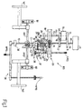
- a transmission 100 shown in Figures 1 and 2 the mechanical power produced by an engine M of a tractor (not shown in its entirety) is transmitted to a first shaft 10, which represents the drive shaft which, as shall be seen, not only sets in rotation the wheels W1 and W2 ( Figure 1), but is also able directly to actuate a rear PTO, RPTO (see below).
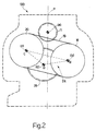
- the axis (a) of the drive shaft 10 lies on a plane of substantial longitudinal symmetry of the tractor.
- the trace of said plane on the sheet is designated with the letter P ( Figure 2).
- gear wheel 13 On the shaft 13 is idle another gear wheel 14.
- the shaft 13 also bears a clutch 15 which, for purpose that will become more readily apparent below, is able to make integral with the shaft 13 either the gear wheel 12 or the gear wheel 14.
- an expandable pulley 18 coupled by means of belt (or chain) 19 to a second pulley 20, also expandable, keyed onto a shaft 21 (having an axis (c)).
- the set of pulleys 18, 20, with the respective shafts 13, 21, and of the belt (or chain) 19 constitutes a device 23 for the continuous variation of motion.
- both shafts 13 and 21 are kinematically united to an epicyclic rotary mechanism 24 having a central shaft 25, whose axis (d) is parallel to the aforesaid axes (a), (b), and (c)).
- a gear wheel 26 On the shaft 13 is keyed a gear wheel 26, whilst a gear wheel 27 is integral with the shaft 21.
- the gear wheel 26 meshes with the sun gear 28 of the epicyclic rotary mechanism 24, idle on the central shaft 25, whilst the wheel 27 transmits motion to a spider 29 mounted idle on a coupling box 28a of the aforesaid sun gear 28.
- the spider 29 In a manner known in itself, to the spider 29 is associated a plurality of satellites 30 (only one is shown in Figure 1), each of which is pivotally engaged to a respective pivot pin 31 in a single piece with the spider 29.
- each planet gear 30 meshes at one side with a gear wheel 32 obtained in a single piece with the sun gear 28, and on the other with an inner toothing 33 of the crown 34 integral with the central shaft 25.
- the central placement both of the drive shaft 10 and of the triangle TR has the additional advantage that the disposition of the different PTOs (Power take offs) of the tractor is particularly convenient.
- triangle TR is positioned in substantially balanced fashion relative to the trace P of the longitudinal plane of symmetry of the tractor ( Figure 2) and that the trace P, in addition to passing through the axis (a) of the drive shaft 10, passes at a very small distance from the axis (d) of the central shaft 25 of the epicyclic rotary mechanism 24.
- the central shaft 25 comprises an additional gear wheel 35 downstream of the epicyclic rotary mechanism 24, said gear wheel can be made to mesh with a gear wheel 36 associated with a motion transmission device 37 and a front PTO, FPTO for actuating a pair of front wheels (not shown), device that will be inserted (with known means) if the tractor is to travel using all four drive wheels.
- the transmission system 100 of the present invention in addition to the aforesaid front PTO, FTPO, and rear PTO, RPTO (which may be connectable/detachable to/from the shaft 10 by means of a clutch 38), can provide for the use of an additional PTO located in intermediate position relative to the first two and designated herein as MPTO.
- the MPTO takes motion from the RPTO by means of a gear train 39 and it serves the purpose of actuating, at the operator's choice, a series of tools (not shown herein) which are positioned in the lower part of the tractor.
Landscapes
- Engineering & Computer Science (AREA)
- Mechanical Engineering (AREA)
- General Engineering & Computer Science (AREA)
- Chemical & Material Sciences (AREA)
- Combustion & Propulsion (AREA)
- Transportation (AREA)
- Transmission Devices (AREA)
Abstract
Description
- The present invention relates to a CVT transmission for motor vehicles, in particular for farm tractors.
- In the field of tractors, transmissions in which a continuous control of speed is effected, called CVT transmissions, are known. In other words, in these transmissions, one is able continuously to regulate the speed of the motor vehicle, throughout the range between the maximum forward speed and the maximum reverse speed.
- In particular, in known solutions, the CVT transmission comprises an apparatus for the continuous variation of the motion in terms of delivered torque and speed. Continuous variation is obtained between two shafts and a differential gear by means of a first mechanical device with fixed transmission ratio, and a second mechanical device with variable transmission ratio; between the first and the second device is interposed an epicyclic rotary mechanism. In these applications, as a second mechanical device with variable transmission ratio, a device comprising two expandable pulleys (with variable diameters) is advantageously used, which device is amply used and therefore will not be described in detail hereafter.
- Such a transmission is known, for example, from the patent EP-B1-0 889 260.
- However, whilst it does assure a reliable continuous speed variation, the transmission described in the aforesaid document has the disadvantage of not being compact and therefore it is not suitable for use in low-power tractors in which the volume of the components constitutes a determining factor.
- For example, in the transmission described in EP-B1-0 889 260 the epicyclic rotary mechanism is positioned at the central axis of one of the two expandable pulley. This clearly entails transverse dimensions which are penalising in the field of low-power tractors.
- The object of the present invention, therefore, is to provide a CVT transmission for motor vehicles, in particular for low-power farm tractors, which is free of the aforesaid drawback.
- Therefore according to the present invention a CVT transmission for motor vehicles is provided, in particular for farm tractors as claimed by the characteristics set out in
claim 1. - The present invention will now be described further, with reference to the accompanying drawings, which show a non limiting embodiment example, in which:
- Figure 1 schematically shows a plan view of a CVT transmission for motor vehicles, in particular for farm tractors, according to the present invention; and
- Figure 2 shows a front view of the transmission of Figure 1 (in 2:1 scale relative to the drawing of Figure 1); the outer profile of the motor vehicle being shown in dashed lines.
-
- In a
transmission 100 shown in Figures 1 and 2, the mechanical power produced by an engine M of a tractor (not shown in its entirety) is transmitted to afirst shaft 10, which represents the drive shaft which, as shall be seen, not only sets in rotation the wheels W1 and W2 (Figure 1), but is also able directly to actuate a rear PTO, RPTO (see below). - As shown in Figure 2, the axis (a) of the
drive shaft 10 lies on a plane of substantial longitudinal symmetry of the tractor. The trace of said plane on the sheet is designated with the letter P (Figure 2). - On the
drive shaft 10 is keyed agear wheel 11 meshed with anotheridle gear wheel 11 on a shaft 13 (having an axis (b)) parallel to thedrive shaft 10 itself (with axis (a)). - Moreover, on the
shaft 13 is idle anothergear wheel 14. Theshaft 13 also bears aclutch 15 which, for purpose that will become more readily apparent below, is able to make integral with theshaft 13 either the gear wheel 12 or thegear wheel 14. - The
gear wheel 14, in turn, through anidle gear wheel 16 meshes with agear wheel 17, also keyed on theaforementioned drive shaft 10. - If the gear wheel 12 is made integral with the
shaft 13 by the clutch 15 (and, consequently, thegear wheel 14 on theshaft 13 is made idle), motion is transmitted by thedrive shaft 10 to theshaft 13 in "direct" fashion, i.e. in other words the motor vehicle will travel ''in forward running mode", whilst if thegear wheel 14 is keyed on the shaft 13 (and consequently, the gear wheel 12 on theshaft 13 is made idle) then motion is transmitted by thedrive shaft 10 to theshaft 13 in "reverse" fashion, i.e. in other words the tractor will travel "in reverse running mode", thanks to the presence of theidle gear wheel 16. - On the
shaft 13 is also keyed anexpandable pulley 18, coupled by means of belt (or chain) 19 to asecond pulley 20, also expandable, keyed onto a shaft 21 (having an axis (c)). - The set of
pulleys respective shafts device 23 for the continuous variation of motion. - As shall be seen, both
shafts rotary mechanism 24 having acentral shaft 25, whose axis (d) is parallel to the aforesaid axes (a), (b), and (c)). - For this purpose, on the
shaft 13 is keyed agear wheel 26, whilst agear wheel 27 is integral with theshaft 21. - Respectively, the
gear wheel 26 meshes with thesun gear 28 of theepicyclic rotary mechanism 24, idle on thecentral shaft 25, whilst thewheel 27 transmits motion to a spider 29 mounted idle on acoupling box 28a of theaforesaid sun gear 28. - In a manner known in itself, to the spider 29 is associated a plurality of satellites 30 (only one is shown in Figure 1), each of which is pivotally engaged to a
respective pivot pin 31 in a single piece with the spider 29. - As shown in Figure 1, each
planet gear 30 meshes at one side with a gear wheel 32 obtained in a single piece with thesun gear 28, and on the other with aninner toothing 33 of thecrown 34 integral with thecentral shaft 25. - In known fashion, at the epicyclic
rotary mechanism 24 the algebraic sum occurs of the motions coming, respectively, from the coupling of thegear wheel 26 with the sun gear 28 (with constant transmission ratio), and from the coupling of thegear wheel 27 with the spider 29 (variable transmission ratio achieved by means of the continuous motion variation device 23). - Exploiting the combinatory effects of the two motions which occur at the epicyclic
rotary mechanism 24 it is possible to obtain the desired continuous speed variation to change in the desired fashion the rotation speed of a bevel pinion C1 meshed with a ring bevel gear C2 belonging to a differential gear DIF. - As is well known, by changing the angular speed of the ring bevel gear C2 over time it is possible to change over time also the speed of the differential gear DIF and hence of the pair of rear wheels W1, W2 joined thereto by means of two axles AX1, respectively AX2 supported, respectively, by a bearing B1 and by a bearing B2.
- Observing Figures 1 and 2 together, it is readily apparent that the axis (d) of the
central shaft 25 of the epicyclicrotary mechanism 24 and the axes (b) and (c) of thepulley 18 and, respectively, of the pulley (20) are positioned according to vertices DBC of a triangle TR. - This physical characteristic translates into a considerable improvement in terms of the compactness of the
transmission 100 and in a remarkable limitation of its transverse dimensions with respect to the plane of symmetry of trace P (Figure 2). - Moreover, the central placement both of the
drive shaft 10 and of the triangle TR has the additional advantage that the disposition of the different PTOs (Power take offs) of the tractor is particularly convenient. - It should also be noted that the triangle TR is positioned in substantially balanced fashion relative to the trace P of the longitudinal plane of symmetry of the tractor (Figure 2) and that the trace P, in addition to passing through the axis (a) of the
drive shaft 10, passes at a very small distance from the axis (d) of thecentral shaft 25 of the epicyclicrotary mechanism 24. - All this has the consequence of an extreme equilibrium between the transmission members, and an optimal disposition of the parts, to reduce, as much as possible, the transverse dimensions (for example relative to the axis (a) of the transmission shaft 10).
- Moreover, if the
central shaft 25 comprises anadditional gear wheel 35 downstream of theepicyclic rotary mechanism 24, said gear wheel can be made to mesh with agear wheel 36 associated with amotion transmission device 37 and a front PTO, FPTO for actuating a pair of front wheels (not shown), device that will be inserted (with known means) if the tractor is to travel using all four drive wheels. - Advantageously, the
transmission system 100 of the present invention, in addition to the aforesaid front PTO, FTPO, and rear PTO, RPTO (which may be connectable/detachable to/from theshaft 10 by means of a clutch 38), can provide for the use of an additional PTO located in intermediate position relative to the first two and designated herein as MPTO. - The MPTO takes motion from the RPTO by means of a
gear train 39 and it serves the purpose of actuating, at the operator's choice, a series of tools (not shown herein) which are positioned in the lower part of the tractor.
Claims (5)
- A CVT transmission (100) for motor vehicles, in particular for farm tractors, comprising a first transmission system by means of first mechanical means (26, 28) with fixed transmission ratio, and a second transmission system through second mechanical means (23, 27, 29) with variable transmission ratio, between said first mechanical means (16, 28) and said second mechanical means (23, 27, 29) being interposed an epicyclic rotary mechanism (24) for the combination of the two transmission systems; and
characterized in that :said second mechanical means (23, 27, 29) comprises a pair of pulleys (18, 20), with axes ((b), (c)), able to transmit motion between them by means of a member (19);said epicyclic rotary mechanism (24) comprises a central shaft (25) with axis (d); andsaid axes ((d), (b), (c)) are positioned according to vertices (DBC) of a triangle (TR). - A CVT transmission (100) as claimed in claim 1, wherein said triangle (TR) is arranged in substantially balanced fashion relative to a trace (P) of a longitudinal plane of symmetry of said motor vehicle.
- A CVT transmission (100) as claimed in claim 2, wherein said trace (P) passes through an axis (a) of a drive shaft (10) and it also passes at a small distance from said axis (d) of said central shaft of symmetry (25) of said epicyclic rotary mechanism (24).
- A CVT transmission (100) as claimed in any of the previous claims, wherein on said central shaft (25) is keyed a gear wheel (35) whereby motion is sent to a forward PTO (FPTO) able to set in motion two front wheels of said motor vehicle to achieve a traction with four driving wheels.
- A CVT transmission (100) as claimed in any of the previous claims, wherein the drive shaft (10) directly actuates a rear PTO (RPTO), which, in turn, actuates an intermediate PTO (MPTO) able to set in motion a plurality of tools positioned underneath the motor vehicle.
Applications Claiming Priority (2)
| Application Number | Priority Date | Filing Date | Title |
|---|---|---|---|
| IT000017A ITBO20040017A1 (en) | 2004-01-16 | 2004-01-16 | CVT TRANSMISSION FOR MOTOR VEHICLES, IN PARTICULAR PRE AGRICULTURAL TRACTORS. |
| ITBO20040017 | 2004-01-16 |
Publications (2)
| Publication Number | Publication Date |
|---|---|
| EP1555458A2 true EP1555458A2 (en) | 2005-07-20 |
| EP1555458A3 EP1555458A3 (en) | 2007-04-18 |
Family
ID=34611216
Family Applications (1)
| Application Number | Title | Priority Date | Filing Date |
|---|---|---|---|
| EP05100172A Withdrawn EP1555458A3 (en) | 2004-01-16 | 2005-01-13 | CVT transmission for motor vehicles, in particular for farm tractors. |
Country Status (3)
| Country | Link |
|---|---|
| US (1) | US20050187047A1 (en) |
| EP (1) | EP1555458A3 (en) |
| IT (1) | ITBO20040017A1 (en) |
Cited By (1)
| Publication number | Priority date | Publication date | Assignee | Title |
|---|---|---|---|---|
| WO2007052217A1 (en) * | 2005-11-02 | 2007-05-10 | Graziano Trasmissioni S.P.A. | Continuously-variable-ratio transmission |
Families Citing this family (1)
| Publication number | Priority date | Publication date | Assignee | Title |
|---|---|---|---|---|
| US9970521B1 (en) | 2016-02-26 | 2018-05-15 | Rodney J. Cook and successors in trust | Infinitely variable transmission |
Citations (9)
| Publication number | Priority date | Publication date | Assignee | Title |
|---|---|---|---|---|
| FR1359986A (en) * | 1962-05-21 | 1964-04-30 | Deere & Co | Variable speed transmission, combined with satellite control |
| DE1185883B (en) * | 1959-10-09 | 1965-01-21 | Massey Ferguson Inc | Gear arrangement with power split |
| FR2305651A1 (en) * | 1975-03-24 | 1976-10-22 | Nat Invest Holding Inc | Transmission for agricultural implement - with variable ratio wheel drive and fixed power take off |
| US4579183A (en) * | 1984-02-20 | 1986-04-01 | Kanzaki Kokyukoki Mfg. Co., Ltd. | Transmission for self-propelled working vehicles |
| EP0809044A2 (en) * | 1996-05-25 | 1997-11-26 | ZF FRIEDRICHSHAFEN Aktiengesellschaft | Continuously variable transmission |
| DE29816863U1 (en) * | 1997-09-20 | 1999-04-01 | Meyerle, Michael, 88074 Meckenbeuren | Continuously variable transmission, especially with power split |
| DE19944792A1 (en) * | 1998-09-19 | 2000-04-27 | Michael Meyerle | Infinitely variable retro-fit gear for small tractor power take-off point, with either hydrostatic or mechanical converter to transmit small proportion of engine power |
| US20020094911A1 (en) * | 2001-01-16 | 2002-07-18 | Haka Raymond James | Dual mode, geared neutral continuously variable transmission |
| EP1378686A2 (en) * | 2002-07-05 | 2004-01-07 | CNH Italia S.p.A. | A CVT transmission for motor vehicles, in particular for agricultural tractors. |
Family Cites Families (13)
| Publication number | Priority date | Publication date | Assignee | Title |
|---|---|---|---|---|
| US2000593A (en) * | 1933-08-14 | 1935-05-07 | Kentowens Machine Company | Variable speed transmission |
| FR1440883A (en) * | 1964-05-02 | 1966-06-03 | Zahnradfabrik Friedrichshafen | Transmission system |
| GB9323706D0 (en) * | 1993-11-17 | 1994-01-05 | Massey Ferguson Mfg | Transmissions |
| JP3475613B2 (en) * | 1995-11-24 | 2003-12-08 | アイシン・エィ・ダブリュ株式会社 | Continuously variable transmission |
| US6122996A (en) * | 1998-11-20 | 2000-09-26 | Hydro-Gear Limited Partnership | Hydrostatic transmission |
| KR100262593B1 (en) * | 1996-12-17 | 2000-08-01 | 정몽규 | Cvt for vehicle |
| US5980414A (en) * | 1997-04-25 | 1999-11-09 | General Dynamics Land Systems, Inc. | Multi-range, belt-type, continuously variable transmission |
| US5803858A (en) * | 1997-05-23 | 1998-09-08 | General Motors Corporation | Powertrain transmission with torque converter planetary gearing and a continuously variable transmission unit |
| DE19728611A1 (en) * | 1997-07-04 | 1999-02-04 | Zahnradfabrik Friedrichshafen | Continuously variable transmission |
| US6106428A (en) * | 1998-03-23 | 2000-08-22 | Ford Global Technologies, Inc. | Compact dual mode continually variable transmission |
| JP3954928B2 (en) * | 2002-08-20 | 2007-08-08 | 本田技研工業株式会社 | Vehicle power transmission device |
| JP2004144138A (en) * | 2002-10-22 | 2004-05-20 | Honda Motor Co Ltd | Transmission for vehicle |
| US6986725B2 (en) * | 2002-11-01 | 2006-01-17 | Eaton Corporation | Continuously variable stepped transmission |
-
2004
- 2004-01-16 IT IT000017A patent/ITBO20040017A1/en unknown
-
2005
- 2005-01-13 EP EP05100172A patent/EP1555458A3/en not_active Withdrawn
- 2005-01-18 US US11/037,271 patent/US20050187047A1/en not_active Abandoned
Patent Citations (9)
| Publication number | Priority date | Publication date | Assignee | Title |
|---|---|---|---|---|
| DE1185883B (en) * | 1959-10-09 | 1965-01-21 | Massey Ferguson Inc | Gear arrangement with power split |
| FR1359986A (en) * | 1962-05-21 | 1964-04-30 | Deere & Co | Variable speed transmission, combined with satellite control |
| FR2305651A1 (en) * | 1975-03-24 | 1976-10-22 | Nat Invest Holding Inc | Transmission for agricultural implement - with variable ratio wheel drive and fixed power take off |
| US4579183A (en) * | 1984-02-20 | 1986-04-01 | Kanzaki Kokyukoki Mfg. Co., Ltd. | Transmission for self-propelled working vehicles |
| EP0809044A2 (en) * | 1996-05-25 | 1997-11-26 | ZF FRIEDRICHSHAFEN Aktiengesellschaft | Continuously variable transmission |
| DE29816863U1 (en) * | 1997-09-20 | 1999-04-01 | Meyerle, Michael, 88074 Meckenbeuren | Continuously variable transmission, especially with power split |
| DE19944792A1 (en) * | 1998-09-19 | 2000-04-27 | Michael Meyerle | Infinitely variable retro-fit gear for small tractor power take-off point, with either hydrostatic or mechanical converter to transmit small proportion of engine power |
| US20020094911A1 (en) * | 2001-01-16 | 2002-07-18 | Haka Raymond James | Dual mode, geared neutral continuously variable transmission |
| EP1378686A2 (en) * | 2002-07-05 | 2004-01-07 | CNH Italia S.p.A. | A CVT transmission for motor vehicles, in particular for agricultural tractors. |
Cited By (1)
| Publication number | Priority date | Publication date | Assignee | Title |
|---|---|---|---|---|
| WO2007052217A1 (en) * | 2005-11-02 | 2007-05-10 | Graziano Trasmissioni S.P.A. | Continuously-variable-ratio transmission |
Also Published As
| Publication number | Publication date |
|---|---|
| ITBO20040017A1 (en) | 2004-04-16 |
| US20050187047A1 (en) | 2005-08-25 |
| EP1555458A3 (en) | 2007-04-18 |
Similar Documents
| Publication | Publication Date | Title |
|---|---|---|
| EP2113056B1 (en) | Continuously variable transmission | |
| US9945464B2 (en) | Transmission apparatus | |
| US8262525B2 (en) | Hydrostatic-mechanical power split transmission | |
| US20120142477A1 (en) | Continuously variable ratio transmission | |
| US20100204000A1 (en) | Power-branched transmission | |
| JP4705310B2 (en) | Power train | |
| MXPA04007423A (en) | Continuously variable transmission system. | |
| EP2722212B1 (en) | Hybrid propulsion system for a vehicle and transmission for such a propulsion system | |
| EP1378686B1 (en) | A CVT transmission for motor vehicles, in particular for agricultural tractors. | |
| EP1555458A2 (en) | CVT transmission for motor vehicles, in particular for farm tractors. | |
| KR20100057673A (en) | Variable transmission device for a vehicle | |
| EP1347203A3 (en) | Manual transmission for four-wheel drive vehicle | |
| KR20170038266A (en) | A transmisstion for a working vehicle | |
| JP4812388B2 (en) | Transplanter | |
| US20060169515A1 (en) | Dual-chain transfer case | |
| GB2049073A (en) | Continuously-variable ratio transmission | |
| RU35286U1 (en) | Vehicle creeper (options) | |
| RU62561U1 (en) | PLANETARY TRANSFER BOX | |
| SU1475839A1 (en) | Railway vehicle tarction drive | |
| EP2399046B1 (en) | Continuously variable transmission system | |
| RU2322368C1 (en) | Crawler tractor transmission | |
| JP2004224297A (en) | Travel transmission structure of working vehicle | |
| JPH11155319A (en) | Sulky type traveling farming machine | |
| JP2585279Y2 (en) | Clutch mechanism for paddy field work vehicle | |
| JP2004210068A (en) | Farming machine |
Legal Events
| Date | Code | Title | Description |
|---|---|---|---|
| PUAI | Public reference made under article 153(3) epc to a published international application that has entered the european phase |
Free format text: ORIGINAL CODE: 0009012 |
|
| AK | Designated contracting states |
Kind code of ref document: A2 Designated state(s): AT BE BG CH CY CZ DE DK EE ES FI FR GB GR HU IE IS IT LI LT LU MC NL PL PT RO SE SI SK TR |
|
| AX | Request for extension of the european patent |
Extension state: AL BA HR LV MK YU |
|
| PUAL | Search report despatched |
Free format text: ORIGINAL CODE: 0009013 |
|
| AK | Designated contracting states |
Kind code of ref document: A3 Designated state(s): AT BE BG CH CY CZ DE DK EE ES FI FR GB GR HU IE IS IT LI LT LU MC NL PL PT RO SE SI SK TR |
|
| AX | Request for extension of the european patent |
Extension state: AL BA HR LV MK YU |
|
| 17P | Request for examination filed |
Effective date: 20071018 |
|
| AKX | Designation fees paid |
Designated state(s): AT BE BG CH CY CZ DE DK EE ES FI FR GB GR HU IE IS IT LI LT LU MC NL PL PT RO SE SI SK TR |
|
| 17Q | First examination report despatched |
Effective date: 20090210 |
|
| STAA | Information on the status of an ep patent application or granted ep patent |
Free format text: STATUS: THE APPLICATION IS DEEMED TO BE WITHDRAWN |
|
| 18D | Application deemed to be withdrawn |
Effective date: 20090623 |