EP1555424A1 - Automatisches Wasserentlüftungssystem für Brennstofffilter - Google Patents
Automatisches Wasserentlüftungssystem für Brennstofffilter Download PDFInfo
- Publication number
- EP1555424A1 EP1555424A1 EP05290021A EP05290021A EP1555424A1 EP 1555424 A1 EP1555424 A1 EP 1555424A1 EP 05290021 A EP05290021 A EP 05290021A EP 05290021 A EP05290021 A EP 05290021A EP 1555424 A1 EP1555424 A1 EP 1555424A1
- Authority
- EP
- European Patent Office
- Prior art keywords
- water
- fuel
- filter
- detection device
- zone
- Prior art date
- Legal status (The legal status is an assumption and is not a legal conclusion. Google has not performed a legal analysis and makes no representation as to the accuracy of the status listed.)
- Withdrawn
Links
- XLYOFNOQVPJJNP-UHFFFAOYSA-N water Substances O XLYOFNOQVPJJNP-UHFFFAOYSA-N 0.000 title claims abstract description 102
- 239000000446 fuel Substances 0.000 title claims abstract description 31
- 238000013022 venting Methods 0.000 title 1
- 238000001514 detection method Methods 0.000 claims abstract description 26
- 230000004913 activation Effects 0.000 claims abstract description 12
- 238000000926 separation method Methods 0.000 claims abstract description 5
- 238000010926 purge Methods 0.000 claims description 21
- 239000002283 diesel fuel Substances 0.000 claims description 7
- 239000002828 fuel tank Substances 0.000 claims description 5
- 238000011144 upstream manufacturing Methods 0.000 claims description 4
- 238000010908 decantation Methods 0.000 abstract description 2
- 230000003213 activating effect Effects 0.000 abstract 1
- 235000021183 entrée Nutrition 0.000 description 5
- 239000000839 emulsion Substances 0.000 description 1
- 238000010438 heat treatment Methods 0.000 description 1
- 239000011810 insulating material Substances 0.000 description 1
- 238000009413 insulation Methods 0.000 description 1
- 230000002787 reinforcement Effects 0.000 description 1
- 230000001960 triggered effect Effects 0.000 description 1
- 238000004148 unit process Methods 0.000 description 1
Images


Classifications
-
- B—PERFORMING OPERATIONS; TRANSPORTING
- B01—PHYSICAL OR CHEMICAL PROCESSES OR APPARATUS IN GENERAL
- B01D—SEPARATION
- B01D36/00—Filter circuits or combinations of filters with other separating devices
- B01D36/003—Filters in combination with devices for the removal of liquids
- B01D36/005—Liquid level sensing means, e.g. for water in gasoil-filters
-
- F—MECHANICAL ENGINEERING; LIGHTING; HEATING; WEAPONS; BLASTING
- F02—COMBUSTION ENGINES; HOT-GAS OR COMBUSTION-PRODUCT ENGINE PLANTS
- F02M—SUPPLYING COMBUSTION ENGINES IN GENERAL WITH COMBUSTIBLE MIXTURES OR CONSTITUENTS THEREOF
- F02M37/00—Apparatus or systems for feeding liquid fuel from storage containers to carburettors or fuel-injection apparatus; Arrangements for purifying liquid fuel specially adapted for, or arranged on, internal-combustion engines
- F02M37/22—Arrangements for purifying liquid fuel specially adapted for, or arranged on, internal-combustion engines, e.g. arrangements in the feeding system
- F02M37/24—Arrangements for purifying liquid fuel specially adapted for, or arranged on, internal-combustion engines, e.g. arrangements in the feeding system characterised by water separating means
- F02M37/26—Arrangements for purifying liquid fuel specially adapted for, or arranged on, internal-combustion engines, e.g. arrangements in the feeding system characterised by water separating means with water detection means
- F02M37/28—Arrangements for purifying liquid fuel specially adapted for, or arranged on, internal-combustion engines, e.g. arrangements in the feeding system characterised by water separating means with water detection means with means activated by the presence of water, e.g. alarms or means for automatic drainage
-
- F—MECHANICAL ENGINEERING; LIGHTING; HEATING; WEAPONS; BLASTING
- F02—COMBUSTION ENGINES; HOT-GAS OR COMBUSTION-PRODUCT ENGINE PLANTS
- F02M—SUPPLYING COMBUSTION ENGINES IN GENERAL WITH COMBUSTIBLE MIXTURES OR CONSTITUENTS THEREOF
- F02M37/00—Apparatus or systems for feeding liquid fuel from storage containers to carburettors or fuel-injection apparatus; Arrangements for purifying liquid fuel specially adapted for, or arranged on, internal-combustion engines
- F02M37/22—Arrangements for purifying liquid fuel specially adapted for, or arranged on, internal-combustion engines, e.g. arrangements in the feeding system
- F02M37/32—Arrangements for purifying liquid fuel specially adapted for, or arranged on, internal-combustion engines, e.g. arrangements in the feeding system characterised by filters or filter arrangements
-
- F—MECHANICAL ENGINEERING; LIGHTING; HEATING; WEAPONS; BLASTING
- F02—COMBUSTION ENGINES; HOT-GAS OR COMBUSTION-PRODUCT ENGINE PLANTS
- F02M—SUPPLYING COMBUSTION ENGINES IN GENERAL WITH COMBUSTIBLE MIXTURES OR CONSTITUENTS THEREOF
- F02M37/00—Apparatus or systems for feeding liquid fuel from storage containers to carburettors or fuel-injection apparatus; Arrangements for purifying liquid fuel specially adapted for, or arranged on, internal-combustion engines
- F02M37/22—Arrangements for purifying liquid fuel specially adapted for, or arranged on, internal-combustion engines, e.g. arrangements in the feeding system
- F02M37/30—Arrangements for purifying liquid fuel specially adapted for, or arranged on, internal-combustion engines, e.g. arrangements in the feeding system characterised by heating means
Definitions
- the present invention relates to automatic water purge for fuel filters intended for power a vehicle engine.
- the control unit is generally adapted to trigger or control activation of the electric pump when, on the one hand, the detection device emits a signal indicating the presence of water in the filter's water collection area, and other where, for example, switching means controlled by a vehicle ignition key are placed in an activation position corresponding to the start of the vehicle engine. So when the vehicle user brings the ignition key to the engine start position, and if the detection device detects water in the fuel filter, the control unit processes this information and triggers the purge command up complete emptying of the water contained in the filter to a remote tank. In this case, a relay connected to the unit control prevents the vehicle from starting during the full drain of the fuel filter.
- the present invention is intended in particular to this disadvantage.
- the automatic purge of the water is made after the operation of the engine, that is to say when the high temperature under the engine hood has allowed the water to thaw, thus allowing the pump to drain the water contained in said filter itself negative outdoor temperature.
- Figure 1 shows a purge system automatic water for a diesel filter 1 to be described in more detail in the rest of the description, this filter diesel fuel intended for supplying a diesel engine of vehicle.
- the exit 72 of the electric pump 7 is connected to the inlet 91 of a check valve 9 which also includes an outlet 92 connected to a water reservoir 10 by means of a evacuation line 11.
- control unit 8 of the control system automatic purge comprises a connected control circuit 81 electrically to the detection device 6, as well as a power circuit 82 which is connected electrically to the electric pump 7.
- the circuit of command 81 as well as the power circuit 82 of the unit 8 are connected for example to the battery of the vehicle (not shown) by means of a connector electric 83.
- the control circuit can also be connected to a light 84 placed for example in the table of edge of the vehicle and intended to turn on when the circuit control unit 81 receives a water detection signal from the detection device 6.
- the detection device 6 is adapted to delivering an electrical signal to the control circuit 81 of the control unit 8, when a sufficient amount of water accumulated in the water collection area, and which corresponds to a maximum threshold level.
- the detection device 6 may for example include two electrodes 61 and 62 which can be directly embedded in an insulating material on the major part of their length, except at their end higher.
- the level at which the ends are placed upper electrodes 61,62 corresponds to the level of predetermined warning threshold from which the volume of water 2 collected in the collection zone 2 must be purged.
- This control unit 8 is adapted according to to the invention, to trigger the automatic draining of water from filter 1 after stopping the engine of the vehicle and not before start-up, and if the detector 6 emits a signal indicating the presence of water, as described above.
- control unit 8 is adapted to trigger first a first T1 settling delay when the motor of the vehicle moves from the operating state to the off state, this first decantation delay which is configurable being intended to allow a proper separation of water 3 and diesel 4 contained in the collection zone 2 of the filter 1.
- This settling delay which can be by example of the order of a few minutes, and that is triggered as soon as the engine is stopped allows only the appropriate separation of water 3 contained in the zone of collection 2 in the case of the presence of a water emulsion diesel after use of the vehicle.
- control unit 8 or more precisely the circuit of command 81 can receive signals from the detection 6 indicating the presence of water in the area of collection 2, but in this case said control circuit 81 does not may not trigger the activation of the pump Electric 7.
- the control circuit 81 triggers automatically a second T2 timer during which the control unit is able to control the activation of the electric pump 7 by means of the circuit of power 82 in the case where the detection device 6 sends a signal that the water contained in the zone of collection 2 of filter 1 has reached the alert threshold predetermined.
- the electric pump 7 is activated during all the second time delay T2.
- This second T2 will be determined so that at most half the volume of water 3 contained in the collection zone 2 is sucked up and evacuated by the electric pump 7 so to be brought to the water tank 10 of the vehicle.
- This second timer T2 defined for no more than half of the water collection zone 2 is emptied, guaranteed to only purge water, thus avoiding electric pump 7 also sucks diesel 4.
- the water tank 10 can also be adapted to overcome a possible aspiration of diesel 4 by the electric pump 7.
- the water reserve 10 comprises in part a connected output 12 via a pipe exhaust 13, fuel return circuit 14 intended to return excess diesel fuel that has not been consumed in the vehicle engine towards the diesel tank.
- the diesel exhaust pipe 13 can also be provided with a check valve 13a so avoid any accidental introduction of diesel fuel since return circuit 14 to the water tank 10.
- the filter 1 comprises a head 15 and a cartridge 16 fixed removably relative to each other.
- the head 15 comprises a diesel inlet 17 and a diesel output 18 that are connected to the circuit diesel fuel supply of the vehicle (not shown).
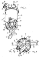
- the head 15 of the filter 1 can also comprise a device for heating diesel fuel 19 (figure 4) which includes for example one or more elements PTC resistive electrically powered via a connector 20.
- the cartridge 16 meanwhile, has a housing 21 waterproof which delimits a hollow interior space in which is housed a filter element 22.
- This filter element 22 separates the hollow interior space into a downstream space 23 which communicates with the exit of diesel 18 and in a space upstream 24 which communicates with the diesel inlet 17 and which also includes in its lower part the zone of water collection 2.
- the lower portion of the housing 21 which forms the zone of water collection 2 has a cross section substantially semi cylindrical thus delimiting at the level the outer wall of the housing 21 a reinforcement 21 also of substantially semi-cylindrical shape in which is fixedly connected the electric pump 7, the valve anti-return 9.
- the water collecting zone 2 comprises a vertical duct 26 open down, in which is attached with tightness, for example by screwing, the detector 6.
- This detector 6 is also equipped with an external electrical connector 63 for to be connected to the control unit 8.
- the bottom of this area collection 2, and the bottom 27 of the housing 21 disposed above the recess 21a includes a plurality of vertical ribs 28 on which is supported axially the filter element 22 contained in the space inside said housing 21.
- the housing 21 also includes at its junction between the water collection zone 2 and the bottom 27 located above the recess 21a, a opening 29 in which is housed in a sealed manner a pin 30 which extends vertically upward until a threaded end in which is screwed a screw 31 housed in a sealed manner in an opening 32 made on the head 15 of the filter 1 so as to fix the head 15 on the housing 21.
- Filter 1 also includes seals 33 and 34 which seal the inlet of diesel 17 at the upstream space 24 and the diesel output 18 at the downstream space 24.
- the housing 21 of the filter 1 or more particularly the recess 21a located in its lower part is adapted to receive the pump electric 7 and the non-return valve 9.
- the electric pump 7 is directly fixed for example by means of clamping rings 35 on the outer wall of the housing 21 and the water outlet 72 of the electric pump is directly connected to the input 91 of the non-return valve 9.
- this non-return valve 9 also includes a water outlet 92 for be connected to the exhaust duct 11 (see Figure 1) allowing the evacuation of the purged water towards the tank of water 10.
- the electric pump 7 also includes an electrical connector 73 for be electrically connected to the control circuit 82 of the control unit 8.
- the water outlet 5 located in the bottom of the collection zone 2 is in the form of a substantially horizontal in which is housed in a fixed and waterproof manner the inlet 71 of the electric pump 7.
Landscapes
- Engineering & Computer Science (AREA)
- Chemical & Material Sciences (AREA)
- Combustion & Propulsion (AREA)
- Mechanical Engineering (AREA)
- General Engineering & Computer Science (AREA)
- Chemical Kinetics & Catalysis (AREA)
- Cooling, Air Intake And Gas Exhaust, And Fuel Tank Arrangements In Propulsion Units (AREA)
- Filtration Of Liquid (AREA)
Applications Claiming Priority (2)
| Application Number | Priority Date | Filing Date | Title |
|---|---|---|---|
| FR0400316A FR2865005B1 (fr) | 2004-01-14 | 2004-01-14 | Systeme de purge automatique d'eau pour filtre a carburant. |
| FR0400316 | 2004-01-14 |
Publications (1)
| Publication Number | Publication Date |
|---|---|
| EP1555424A1 true EP1555424A1 (de) | 2005-07-20 |
Family
ID=34610769
Family Applications (1)
| Application Number | Title | Priority Date | Filing Date |
|---|---|---|---|
| EP05290021A Withdrawn EP1555424A1 (de) | 2004-01-14 | 2005-01-05 | Automatisches Wasserentlüftungssystem für Brennstofffilter |
Country Status (2)
| Country | Link |
|---|---|
| EP (1) | EP1555424A1 (de) |
| FR (1) | FR2865005B1 (de) |
Cited By (3)
| Publication number | Priority date | Publication date | Assignee | Title |
|---|---|---|---|---|
| WO2014145513A1 (en) * | 2013-03-15 | 2014-09-18 | Davco Technology, Llc | Automatic drain for fuel processor |
| CN108661833A (zh) * | 2017-03-27 | 2018-10-16 | 天津宏信设备租赁有限公司 | 一种柴油油水分离装置 |
| CN116696628A (zh) * | 2023-06-25 | 2023-09-05 | 平原滤清器有限公司 | 一种高集成智能化燃油滤清器 |
Citations (9)
| Publication number | Priority date | Publication date | Assignee | Title |
|---|---|---|---|---|
| US4495069A (en) * | 1981-07-27 | 1985-01-22 | Davco, Inc. | Drain system for fuel processor apparatus |
| US4519349A (en) * | 1982-11-08 | 1985-05-28 | Schmelzer Corporation | Water ejector fuel system |
| US4898140A (en) * | 1988-04-11 | 1990-02-06 | Labinal | Devices for eliminating water from diesel oil supplying a diesel engine |
| WO2001033069A1 (en) * | 1999-11-03 | 2001-05-10 | Ufi Universal Filter International S.P.A. | Unit for automatically bleeding off the water which separates in a vehicle fuel filter, in particular for diesel engines |
| WO2001094773A1 (en) * | 2000-06-05 | 2001-12-13 | Ufi Universal Filter International S.P.A. | Apparatus for automatically draining water accumulated in a fuel filter of a vehicle, particularly for diesel engines |
| US6514404B1 (en) * | 1998-10-17 | 2003-02-04 | Filterwerk Mann & Hummel Gmbh | Filter device |
| DE10138695A1 (de) * | 2001-08-07 | 2003-02-20 | Mann & Hummel Filter | Vorrichtung zum Austragen von Wasser aus dem Kraftstoffsystem einer Brennkraftmaschine und Verfahren zu deren Betrieb |
| US20030089648A1 (en) * | 2000-06-05 | 2003-05-15 | Giorgio Girondi | Apparatus for automatically draining water accumulated in a fuel filter of a vehicle, particularly for diesel engines |
| US6596174B1 (en) * | 1998-09-11 | 2003-07-22 | Alexander C. Marcus | Diesel fuel cleaning and re-circulation system |
-
2004
- 2004-01-14 FR FR0400316A patent/FR2865005B1/fr not_active Expired - Lifetime
-
2005
- 2005-01-05 EP EP05290021A patent/EP1555424A1/de not_active Withdrawn
Patent Citations (9)
| Publication number | Priority date | Publication date | Assignee | Title |
|---|---|---|---|---|
| US4495069A (en) * | 1981-07-27 | 1985-01-22 | Davco, Inc. | Drain system for fuel processor apparatus |
| US4519349A (en) * | 1982-11-08 | 1985-05-28 | Schmelzer Corporation | Water ejector fuel system |
| US4898140A (en) * | 1988-04-11 | 1990-02-06 | Labinal | Devices for eliminating water from diesel oil supplying a diesel engine |
| US6596174B1 (en) * | 1998-09-11 | 2003-07-22 | Alexander C. Marcus | Diesel fuel cleaning and re-circulation system |
| US6514404B1 (en) * | 1998-10-17 | 2003-02-04 | Filterwerk Mann & Hummel Gmbh | Filter device |
| WO2001033069A1 (en) * | 1999-11-03 | 2001-05-10 | Ufi Universal Filter International S.P.A. | Unit for automatically bleeding off the water which separates in a vehicle fuel filter, in particular for diesel engines |
| WO2001094773A1 (en) * | 2000-06-05 | 2001-12-13 | Ufi Universal Filter International S.P.A. | Apparatus for automatically draining water accumulated in a fuel filter of a vehicle, particularly for diesel engines |
| US20030089648A1 (en) * | 2000-06-05 | 2003-05-15 | Giorgio Girondi | Apparatus for automatically draining water accumulated in a fuel filter of a vehicle, particularly for diesel engines |
| DE10138695A1 (de) * | 2001-08-07 | 2003-02-20 | Mann & Hummel Filter | Vorrichtung zum Austragen von Wasser aus dem Kraftstoffsystem einer Brennkraftmaschine und Verfahren zu deren Betrieb |
Cited By (5)
| Publication number | Priority date | Publication date | Assignee | Title |
|---|---|---|---|---|
| WO2014145513A1 (en) * | 2013-03-15 | 2014-09-18 | Davco Technology, Llc | Automatic drain for fuel processor |
| US9684313B2 (en) | 2013-03-15 | 2017-06-20 | Davco Technology, Llc | Automatic drain for fuel processor |
| CN108661833A (zh) * | 2017-03-27 | 2018-10-16 | 天津宏信设备租赁有限公司 | 一种柴油油水分离装置 |
| CN116696628A (zh) * | 2023-06-25 | 2023-09-05 | 平原滤清器有限公司 | 一种高集成智能化燃油滤清器 |
| CN116696628B (zh) * | 2023-06-25 | 2025-09-19 | 平原滤清器有限公司 | 一种高集成智能化燃油滤清器 |
Also Published As
| Publication number | Publication date |
|---|---|
| FR2865005B1 (fr) | 2006-05-26 |
| FR2865005A1 (fr) | 2005-07-15 |
Similar Documents
| Publication | Publication Date | Title |
|---|---|---|
| EP3408004B1 (de) | Kraftstofffilter mit einer montagevorrichtung, deren auslass durch ein ventil verschlossen wird, wenn ein filtereinsatz entfernt wird. | |
| EP0780083B1 (de) | Elektrisches Gerät zum Dampfreinigen von glatten Oberflächen wie Fensterscheiben | |
| WO1990007061A1 (fr) | Ensemble de pompage pour l'obtention de vides eleves | |
| FR2594708A1 (fr) | Dispositif de filtrage de carburant du type a chauffage du carburant | |
| FR2549148A1 (fr) | Dispositif combine pour le chauffage et le filtration d'un combustible liquide tel que du gazole | |
| EP1188468B1 (de) | Flüssigkeitsfilter für Dieselkraftstoff mit einem elektrischen Stromkreis und Filtervorrichtung mit solchem Filter | |
| EP1964740B1 (de) | Neuartige funktionelle Architektur eines Vakuumkreislaufs in einem Kraftfahrzeug zur Erhaltung der Integrität der pneumatischen Stellglieder oder Aufnehmer | |
| EP1555424A1 (de) | Automatisches Wasserentlüftungssystem für Brennstofffilter | |
| FR2680393A1 (fr) | Procede et dispositif de commande d'une installation de pompage. | |
| FR2717564A1 (fr) | Agencement de cuve réceptrice de liquide de réfrigérant pour un système de réfrigération destiné notamment à des moyens de transport. | |
| FR2959497A1 (fr) | Reservoir de fluide avec bol de reserve chauffant | |
| FR2940336A1 (fr) | Installation d'evacuation comportant un reservoir equipe d'une pompe de vidage et procede de commande en fonctionnement du moteur de ladite pompe de vidage. | |
| EP1017937A1 (de) | Pumpvorrichtung für dieselkraftstoff eines kraftfahrzeuges | |
| WO2005094965A1 (fr) | Systeme de filtration de liquide comprenant des moyens de chauffage de liquide | |
| FR2834007A1 (fr) | Dispositif pour filtrer du carburant | |
| FR2963285A1 (fr) | Dispositif de remplissage et vehicule automobile equipe d'un tel dispositif de remplissage | |
| FR2882661A1 (fr) | Systeme de filtration de liquide comportant un obturateur de vidange | |
| EP0895020B1 (de) | Vorrichtung zur Einführung von Luft in einem hydropneumatischen Vorratsbehälter | |
| FR2543657A1 (fr) | Soupape automatique d'evacuation de l'eau de condensation dans des installations a air comprime | |
| FR1452838A (fr) | Appareil pour le renouvellement de l'air dans les réservoirs de liquide sous pression | |
| FR2775274A1 (fr) | Ensemble portable pour la commande a distance du remplissage de cuves ou analogues | |
| EP3674492B1 (de) | Tauchbarer sanitärer zerkleinerer | |
| EP3217054B1 (de) | Ablasseinrichtung und pumpe mit dieser einrichtung | |
| FR2922465A1 (fr) | Epurateur d'eau | |
| FR2621959A1 (fr) | Systeme modulaire de rechauffage, filtrage et decantation de carburant, notamment gazole |
Legal Events
| Date | Code | Title | Description |
|---|---|---|---|
| PUAI | Public reference made under article 153(3) epc to a published international application that has entered the european phase |
Free format text: ORIGINAL CODE: 0009012 |
|
| AK | Designated contracting states |
Kind code of ref document: A1 Designated state(s): AT BE BG CH CY CZ DE DK EE ES FI FR GB GR HU IE IS IT LI LT LU MC NL PL PT RO SE SI SK TR |
|
| AX | Request for extension of the european patent |
Extension state: AL BA HR LV MK YU |
|
| 17P | Request for examination filed |
Effective date: 20051112 |
|
| AKX | Designation fees paid |
Designated state(s): AT BE BG CH CY CZ DE DK EE ES FI FR GB GR HU IE IS IT LI LT LU MC NL PL PT RO SE SI SK TR |
|
| 17Q | First examination report despatched |
Effective date: 20060309 |
|
| STAA | Information on the status of an ep patent application or granted ep patent |
Free format text: STATUS: THE APPLICATION IS DEEMED TO BE WITHDRAWN |
|
| 18D | Application deemed to be withdrawn |
Effective date: 20100803 |