EP1555401A1 - Exhaust purifying apparatus for internal combustion engine - Google Patents
Exhaust purifying apparatus for internal combustion engine Download PDFInfo
- Publication number
- EP1555401A1 EP1555401A1 EP05000635A EP05000635A EP1555401A1 EP 1555401 A1 EP1555401 A1 EP 1555401A1 EP 05000635 A EP05000635 A EP 05000635A EP 05000635 A EP05000635 A EP 05000635A EP 1555401 A1 EP1555401 A1 EP 1555401A1
- Authority
- EP
- European Patent Office
- Prior art keywords
- exhaust
- temperature
- purifying member
- exhaust purifying
- clogging
- Prior art date
- Legal status (The legal status is an assumption and is not a legal conclusion. Google has not performed a legal analysis and makes no representation as to the accuracy of the status listed.)
- Granted
Links
Images

Classifications
-
- F—MECHANICAL ENGINEERING; LIGHTING; HEATING; WEAPONS; BLASTING
- F01—MACHINES OR ENGINES IN GENERAL; ENGINE PLANTS IN GENERAL; STEAM ENGINES
- F01N—GAS-FLOW SILENCERS OR EXHAUST APPARATUS FOR MACHINES OR ENGINES IN GENERAL; GAS-FLOW SILENCERS OR EXHAUST APPARATUS FOR INTERNAL COMBUSTION ENGINES
- F01N3/00—Exhaust or silencing apparatus having means for purifying, rendering innocuous, or otherwise treating exhaust
- F01N3/02—Exhaust or silencing apparatus having means for purifying, rendering innocuous, or otherwise treating exhaust for cooling, or for removing solid constituents of, exhaust
- F01N3/021—Exhaust or silencing apparatus having means for purifying, rendering innocuous, or otherwise treating exhaust for cooling, or for removing solid constituents of, exhaust by means of filters
- F01N3/023—Exhaust or silencing apparatus having means for purifying, rendering innocuous, or otherwise treating exhaust for cooling, or for removing solid constituents of, exhaust by means of filters using means for regenerating the filters, e.g. by burning trapped particles
- F01N3/0235—Exhaust or silencing apparatus having means for purifying, rendering innocuous, or otherwise treating exhaust for cooling, or for removing solid constituents of, exhaust by means of filters using means for regenerating the filters, e.g. by burning trapped particles using exhaust gas throttling means
-
- F—MECHANICAL ENGINEERING; LIGHTING; HEATING; WEAPONS; BLASTING
- F01—MACHINES OR ENGINES IN GENERAL; ENGINE PLANTS IN GENERAL; STEAM ENGINES
- F01N—GAS-FLOW SILENCERS OR EXHAUST APPARATUS FOR MACHINES OR ENGINES IN GENERAL; GAS-FLOW SILENCERS OR EXHAUST APPARATUS FOR INTERNAL COMBUSTION ENGINES
- F01N11/00—Monitoring or diagnostic devices for exhaust-gas treatment apparatus, e.g. for catalytic activity
- F01N11/002—Monitoring or diagnostic devices for exhaust-gas treatment apparatus, e.g. for catalytic activity the diagnostic devices measuring or estimating temperature or pressure in, or downstream of the exhaust apparatus
-
- F—MECHANICAL ENGINEERING; LIGHTING; HEATING; WEAPONS; BLASTING
- F01—MACHINES OR ENGINES IN GENERAL; ENGINE PLANTS IN GENERAL; STEAM ENGINES
- F01N—GAS-FLOW SILENCERS OR EXHAUST APPARATUS FOR MACHINES OR ENGINES IN GENERAL; GAS-FLOW SILENCERS OR EXHAUST APPARATUS FOR INTERNAL COMBUSTION ENGINES
- F01N13/00—Exhaust or silencing apparatus characterised by constructional features ; Exhaust or silencing apparatus, or parts thereof, having pertinent characteristics not provided for in, or of interest apart from, groups F01N1/00 - F01N5/00, F01N9/00, F01N11/00
- F01N13/009—Exhaust or silencing apparatus characterised by constructional features ; Exhaust or silencing apparatus, or parts thereof, having pertinent characteristics not provided for in, or of interest apart from, groups F01N1/00 - F01N5/00, F01N9/00, F01N11/00 having two or more separate purifying devices arranged in series
- F01N13/0097—Exhaust or silencing apparatus characterised by constructional features ; Exhaust or silencing apparatus, or parts thereof, having pertinent characteristics not provided for in, or of interest apart from, groups F01N1/00 - F01N5/00, F01N9/00, F01N11/00 having two or more separate purifying devices arranged in series the purifying devices are arranged in a single housing
-
- F—MECHANICAL ENGINEERING; LIGHTING; HEATING; WEAPONS; BLASTING
- F01—MACHINES OR ENGINES IN GENERAL; ENGINE PLANTS IN GENERAL; STEAM ENGINES
- F01N—GAS-FLOW SILENCERS OR EXHAUST APPARATUS FOR MACHINES OR ENGINES IN GENERAL; GAS-FLOW SILENCERS OR EXHAUST APPARATUS FOR INTERNAL COMBUSTION ENGINES
- F01N3/00—Exhaust or silencing apparatus having means for purifying, rendering innocuous, or otherwise treating exhaust
- F01N3/02—Exhaust or silencing apparatus having means for purifying, rendering innocuous, or otherwise treating exhaust for cooling, or for removing solid constituents of, exhaust
- F01N3/021—Exhaust or silencing apparatus having means for purifying, rendering innocuous, or otherwise treating exhaust for cooling, or for removing solid constituents of, exhaust by means of filters
- F01N3/023—Exhaust or silencing apparatus having means for purifying, rendering innocuous, or otherwise treating exhaust for cooling, or for removing solid constituents of, exhaust by means of filters using means for regenerating the filters, e.g. by burning trapped particles
- F01N3/025—Exhaust or silencing apparatus having means for purifying, rendering innocuous, or otherwise treating exhaust for cooling, or for removing solid constituents of, exhaust by means of filters using means for regenerating the filters, e.g. by burning trapped particles using fuel burner or by adding fuel to exhaust
- F01N3/0253—Exhaust or silencing apparatus having means for purifying, rendering innocuous, or otherwise treating exhaust for cooling, or for removing solid constituents of, exhaust by means of filters using means for regenerating the filters, e.g. by burning trapped particles using fuel burner or by adding fuel to exhaust adding fuel to exhaust gases
-
- F—MECHANICAL ENGINEERING; LIGHTING; HEATING; WEAPONS; BLASTING
- F01—MACHINES OR ENGINES IN GENERAL; ENGINE PLANTS IN GENERAL; STEAM ENGINES
- F01N—GAS-FLOW SILENCERS OR EXHAUST APPARATUS FOR MACHINES OR ENGINES IN GENERAL; GAS-FLOW SILENCERS OR EXHAUST APPARATUS FOR INTERNAL COMBUSTION ENGINES
- F01N3/00—Exhaust or silencing apparatus having means for purifying, rendering innocuous, or otherwise treating exhaust
- F01N3/02—Exhaust or silencing apparatus having means for purifying, rendering innocuous, or otherwise treating exhaust for cooling, or for removing solid constituents of, exhaust
- F01N3/021—Exhaust or silencing apparatus having means for purifying, rendering innocuous, or otherwise treating exhaust for cooling, or for removing solid constituents of, exhaust by means of filters
- F01N3/023—Exhaust or silencing apparatus having means for purifying, rendering innocuous, or otherwise treating exhaust for cooling, or for removing solid constituents of, exhaust by means of filters using means for regenerating the filters, e.g. by burning trapped particles
- F01N3/029—Exhaust or silencing apparatus having means for purifying, rendering innocuous, or otherwise treating exhaust for cooling, or for removing solid constituents of, exhaust by means of filters using means for regenerating the filters, e.g. by burning trapped particles by adding non-fuel substances to exhaust
-
- F—MECHANICAL ENGINEERING; LIGHTING; HEATING; WEAPONS; BLASTING
- F01—MACHINES OR ENGINES IN GENERAL; ENGINE PLANTS IN GENERAL; STEAM ENGINES
- F01N—GAS-FLOW SILENCERS OR EXHAUST APPARATUS FOR MACHINES OR ENGINES IN GENERAL; GAS-FLOW SILENCERS OR EXHAUST APPARATUS FOR INTERNAL COMBUSTION ENGINES
- F01N3/00—Exhaust or silencing apparatus having means for purifying, rendering innocuous, or otherwise treating exhaust
- F01N3/02—Exhaust or silencing apparatus having means for purifying, rendering innocuous, or otherwise treating exhaust for cooling, or for removing solid constituents of, exhaust
- F01N3/021—Exhaust or silencing apparatus having means for purifying, rendering innocuous, or otherwise treating exhaust for cooling, or for removing solid constituents of, exhaust by means of filters
- F01N3/033—Exhaust or silencing apparatus having means for purifying, rendering innocuous, or otherwise treating exhaust for cooling, or for removing solid constituents of, exhaust by means of filters in combination with other devices
- F01N3/035—Exhaust or silencing apparatus having means for purifying, rendering innocuous, or otherwise treating exhaust for cooling, or for removing solid constituents of, exhaust by means of filters in combination with other devices with catalytic reactors, e.g. catalysed diesel particulate filters
-
- F—MECHANICAL ENGINEERING; LIGHTING; HEATING; WEAPONS; BLASTING
- F01—MACHINES OR ENGINES IN GENERAL; ENGINE PLANTS IN GENERAL; STEAM ENGINES
- F01N—GAS-FLOW SILENCERS OR EXHAUST APPARATUS FOR MACHINES OR ENGINES IN GENERAL; GAS-FLOW SILENCERS OR EXHAUST APPARATUS FOR INTERNAL COMBUSTION ENGINES
- F01N3/00—Exhaust or silencing apparatus having means for purifying, rendering innocuous, or otherwise treating exhaust
- F01N3/08—Exhaust or silencing apparatus having means for purifying, rendering innocuous, or otherwise treating exhaust for rendering innocuous
- F01N3/0807—Exhaust or silencing apparatus having means for purifying, rendering innocuous, or otherwise treating exhaust for rendering innocuous by using absorbents or adsorbents
- F01N3/0814—Exhaust or silencing apparatus having means for purifying, rendering innocuous, or otherwise treating exhaust for rendering innocuous by using absorbents or adsorbents combined with catalytic converters, e.g. NOx absorption/storage reduction catalysts
-
- F—MECHANICAL ENGINEERING; LIGHTING; HEATING; WEAPONS; BLASTING
- F01—MACHINES OR ENGINES IN GENERAL; ENGINE PLANTS IN GENERAL; STEAM ENGINES
- F01N—GAS-FLOW SILENCERS OR EXHAUST APPARATUS FOR MACHINES OR ENGINES IN GENERAL; GAS-FLOW SILENCERS OR EXHAUST APPARATUS FOR INTERNAL COMBUSTION ENGINES
- F01N3/00—Exhaust or silencing apparatus having means for purifying, rendering innocuous, or otherwise treating exhaust
- F01N3/08—Exhaust or silencing apparatus having means for purifying, rendering innocuous, or otherwise treating exhaust for rendering innocuous
- F01N3/0807—Exhaust or silencing apparatus having means for purifying, rendering innocuous, or otherwise treating exhaust for rendering innocuous by using absorbents or adsorbents
- F01N3/0828—Exhaust or silencing apparatus having means for purifying, rendering innocuous, or otherwise treating exhaust for rendering innocuous by using absorbents or adsorbents characterised by the absorbed or adsorbed substances
- F01N3/0842—Nitrogen oxides
-
- F—MECHANICAL ENGINEERING; LIGHTING; HEATING; WEAPONS; BLASTING
- F01—MACHINES OR ENGINES IN GENERAL; ENGINE PLANTS IN GENERAL; STEAM ENGINES
- F01N—GAS-FLOW SILENCERS OR EXHAUST APPARATUS FOR MACHINES OR ENGINES IN GENERAL; GAS-FLOW SILENCERS OR EXHAUST APPARATUS FOR INTERNAL COMBUSTION ENGINES
- F01N9/00—Electrical control of exhaust gas treating apparatus
- F01N9/002—Electrical control of exhaust gas treating apparatus of filter regeneration, e.g. detection of clogging
-
- F—MECHANICAL ENGINEERING; LIGHTING; HEATING; WEAPONS; BLASTING
- F02—COMBUSTION ENGINES; HOT-GAS OR COMBUSTION-PRODUCT ENGINE PLANTS
- F02D—CONTROLLING COMBUSTION ENGINES
- F02D41/00—Electrical control of supply of combustible mixture or its constituents
- F02D41/02—Circuit arrangements for generating control signals
- F02D41/021—Introducing corrections for particular conditions exterior to the engine
- F02D41/0235—Introducing corrections for particular conditions exterior to the engine in relation with the state of the exhaust gas treating apparatus
- F02D41/027—Introducing corrections for particular conditions exterior to the engine in relation with the state of the exhaust gas treating apparatus to purge or regenerate the exhaust gas treating apparatus
- F02D41/029—Introducing corrections for particular conditions exterior to the engine in relation with the state of the exhaust gas treating apparatus to purge or regenerate the exhaust gas treating apparatus the exhaust gas treating apparatus being a particulate filter
-
- F—MECHANICAL ENGINEERING; LIGHTING; HEATING; WEAPONS; BLASTING
- F02—COMBUSTION ENGINES; HOT-GAS OR COMBUSTION-PRODUCT ENGINE PLANTS
- F02D—CONTROLLING COMBUSTION ENGINES
- F02D41/00—Electrical control of supply of combustible mixture or its constituents
- F02D41/22—Safety or indicating devices for abnormal conditions
-
- F—MECHANICAL ENGINEERING; LIGHTING; HEATING; WEAPONS; BLASTING
- F01—MACHINES OR ENGINES IN GENERAL; ENGINE PLANTS IN GENERAL; STEAM ENGINES
- F01N—GAS-FLOW SILENCERS OR EXHAUST APPARATUS FOR MACHINES OR ENGINES IN GENERAL; GAS-FLOW SILENCERS OR EXHAUST APPARATUS FOR INTERNAL COMBUSTION ENGINES
- F01N2240/00—Combination or association of two or more different exhaust treating devices, or of at least one such device with an auxiliary device, not covered by indexing codes F01N2230/00 or F01N2250/00, one of the devices being
- F01N2240/36—Combination or association of two or more different exhaust treating devices, or of at least one such device with an auxiliary device, not covered by indexing codes F01N2230/00 or F01N2250/00, one of the devices being an exhaust flap
-
- F—MECHANICAL ENGINEERING; LIGHTING; HEATING; WEAPONS; BLASTING
- F01—MACHINES OR ENGINES IN GENERAL; ENGINE PLANTS IN GENERAL; STEAM ENGINES
- F01N—GAS-FLOW SILENCERS OR EXHAUST APPARATUS FOR MACHINES OR ENGINES IN GENERAL; GAS-FLOW SILENCERS OR EXHAUST APPARATUS FOR INTERNAL COMBUSTION ENGINES
- F01N2250/00—Combinations of different methods of purification
- F01N2250/02—Combinations of different methods of purification filtering and catalytic conversion
-
- F—MECHANICAL ENGINEERING; LIGHTING; HEATING; WEAPONS; BLASTING
- F01—MACHINES OR ENGINES IN GENERAL; ENGINE PLANTS IN GENERAL; STEAM ENGINES
- F01N—GAS-FLOW SILENCERS OR EXHAUST APPARATUS FOR MACHINES OR ENGINES IN GENERAL; GAS-FLOW SILENCERS OR EXHAUST APPARATUS FOR INTERNAL COMBUSTION ENGINES
- F01N2550/00—Monitoring or diagnosing the deterioration of exhaust systems
- F01N2550/05—Systems for adding substances into exhaust
-
- F—MECHANICAL ENGINEERING; LIGHTING; HEATING; WEAPONS; BLASTING
- F01—MACHINES OR ENGINES IN GENERAL; ENGINE PLANTS IN GENERAL; STEAM ENGINES
- F01N—GAS-FLOW SILENCERS OR EXHAUST APPARATUS FOR MACHINES OR ENGINES IN GENERAL; GAS-FLOW SILENCERS OR EXHAUST APPARATUS FOR INTERNAL COMBUSTION ENGINES
- F01N2560/00—Exhaust systems with means for detecting or measuring exhaust gas components or characteristics
- F01N2560/06—Exhaust systems with means for detecting or measuring exhaust gas components or characteristics the means being a temperature sensor
-
- F—MECHANICAL ENGINEERING; LIGHTING; HEATING; WEAPONS; BLASTING
- F01—MACHINES OR ENGINES IN GENERAL; ENGINE PLANTS IN GENERAL; STEAM ENGINES
- F01N—GAS-FLOW SILENCERS OR EXHAUST APPARATUS FOR MACHINES OR ENGINES IN GENERAL; GAS-FLOW SILENCERS OR EXHAUST APPARATUS FOR INTERNAL COMBUSTION ENGINES
- F01N2610/00—Adding substances to exhaust gases
- F01N2610/03—Adding substances to exhaust gases the substance being hydrocarbons, e.g. engine fuel
-
- F—MECHANICAL ENGINEERING; LIGHTING; HEATING; WEAPONS; BLASTING
- F02—COMBUSTION ENGINES; HOT-GAS OR COMBUSTION-PRODUCT ENGINE PLANTS
- F02B—INTERNAL-COMBUSTION PISTON ENGINES; COMBUSTION ENGINES IN GENERAL
- F02B29/00—Engines characterised by provision for charging or scavenging not provided for in groups F02B25/00, F02B27/00 or F02B33/00 - F02B39/00; Details thereof
- F02B29/04—Cooling of air intake supply
-
- F—MECHANICAL ENGINEERING; LIGHTING; HEATING; WEAPONS; BLASTING
- F02—COMBUSTION ENGINES; HOT-GAS OR COMBUSTION-PRODUCT ENGINE PLANTS
- F02B—INTERNAL-COMBUSTION PISTON ENGINES; COMBUSTION ENGINES IN GENERAL
- F02B37/00—Engines characterised by provision of pumps driven at least for part of the time by exhaust
-
- F—MECHANICAL ENGINEERING; LIGHTING; HEATING; WEAPONS; BLASTING
- F02—COMBUSTION ENGINES; HOT-GAS OR COMBUSTION-PRODUCT ENGINE PLANTS
- F02D—CONTROLLING COMBUSTION ENGINES
- F02D2200/00—Input parameters for engine control
- F02D2200/02—Input parameters for engine control the parameters being related to the engine
- F02D2200/08—Exhaust gas treatment apparatus parameters
- F02D2200/0812—Particle filter loading
-
- F—MECHANICAL ENGINEERING; LIGHTING; HEATING; WEAPONS; BLASTING
- F02—COMBUSTION ENGINES; HOT-GAS OR COMBUSTION-PRODUCT ENGINE PLANTS
- F02D—CONTROLLING COMBUSTION ENGINES
- F02D41/00—Electrical control of supply of combustible mixture or its constituents
- F02D41/02—Circuit arrangements for generating control signals
- F02D41/021—Introducing corrections for particular conditions exterior to the engine
- F02D41/0235—Introducing corrections for particular conditions exterior to the engine in relation with the state of the exhaust gas treating apparatus
-
- F—MECHANICAL ENGINEERING; LIGHTING; HEATING; WEAPONS; BLASTING
- F02—COMBUSTION ENGINES; HOT-GAS OR COMBUSTION-PRODUCT ENGINE PLANTS
- F02D—CONTROLLING COMBUSTION ENGINES
- F02D41/00—Electrical control of supply of combustible mixture or its constituents
- F02D41/02—Circuit arrangements for generating control signals
- F02D41/14—Introducing closed-loop corrections
- F02D41/1438—Introducing closed-loop corrections using means for determining characteristics of the combustion gases; Sensors therefor
- F02D41/1444—Introducing closed-loop corrections using means for determining characteristics of the combustion gases; Sensors therefor characterised by the characteristics of the combustion gases
- F02D41/1446—Introducing closed-loop corrections using means for determining characteristics of the combustion gases; Sensors therefor characterised by the characteristics of the combustion gases the characteristics being exhaust temperatures
-
- F—MECHANICAL ENGINEERING; LIGHTING; HEATING; WEAPONS; BLASTING
- F02—COMBUSTION ENGINES; HOT-GAS OR COMBUSTION-PRODUCT ENGINE PLANTS
- F02M—SUPPLYING COMBUSTION ENGINES IN GENERAL WITH COMBUSTIBLE MIXTURES OR CONSTITUENTS THEREOF
- F02M26/00—Engine-pertinent apparatus for adding exhaust gases to combustion-air, main fuel or fuel-air mixture, e.g. by exhaust gas recirculation [EGR] systems
- F02M26/02—EGR systems specially adapted for supercharged engines
- F02M26/04—EGR systems specially adapted for supercharged engines with a single turbocharger
- F02M26/05—High pressure loops, i.e. wherein recirculated exhaust gas is taken out from the exhaust system upstream of the turbine and reintroduced into the intake system downstream of the compressor
-
- F—MECHANICAL ENGINEERING; LIGHTING; HEATING; WEAPONS; BLASTING
- F02—COMBUSTION ENGINES; HOT-GAS OR COMBUSTION-PRODUCT ENGINE PLANTS
- F02M—SUPPLYING COMBUSTION ENGINES IN GENERAL WITH COMBUSTIBLE MIXTURES OR CONSTITUENTS THEREOF
- F02M26/00—Engine-pertinent apparatus for adding exhaust gases to combustion-air, main fuel or fuel-air mixture, e.g. by exhaust gas recirculation [EGR] systems
- F02M26/13—Arrangement or layout of EGR passages, e.g. in relation to specific engine parts or for incorporation of accessories
- F02M26/22—Arrangement or layout of EGR passages, e.g. in relation to specific engine parts or for incorporation of accessories with coolers in the recirculation passage
- F02M26/23—Layout, e.g. schematics
-
- F—MECHANICAL ENGINEERING; LIGHTING; HEATING; WEAPONS; BLASTING
- F02—COMBUSTION ENGINES; HOT-GAS OR COMBUSTION-PRODUCT ENGINE PLANTS
- F02M—SUPPLYING COMBUSTION ENGINES IN GENERAL WITH COMBUSTIBLE MIXTURES OR CONSTITUENTS THEREOF
- F02M26/00—Engine-pertinent apparatus for adding exhaust gases to combustion-air, main fuel or fuel-air mixture, e.g. by exhaust gas recirculation [EGR] systems
- F02M26/45—Sensors specially adapted for EGR systems
- F02M26/48—EGR valve position sensors
-
- Y—GENERAL TAGGING OF NEW TECHNOLOGICAL DEVELOPMENTS; GENERAL TAGGING OF CROSS-SECTIONAL TECHNOLOGIES SPANNING OVER SEVERAL SECTIONS OF THE IPC; TECHNICAL SUBJECTS COVERED BY FORMER USPC CROSS-REFERENCE ART COLLECTIONS [XRACs] AND DIGESTS
- Y02—TECHNOLOGIES OR APPLICATIONS FOR MITIGATION OR ADAPTATION AGAINST CLIMATE CHANGE
- Y02T—CLIMATE CHANGE MITIGATION TECHNOLOGIES RELATED TO TRANSPORTATION
- Y02T10/00—Road transport of goods or passengers
- Y02T10/10—Internal combustion engine [ICE] based vehicles
- Y02T10/40—Engine management systems
Definitions
- the present invention relates to an exhaust purifying apparatus for an internal combustion engine.
- Exhaust systems of some engines include an exhaust purifying member such as a carrier incorporating a NOx purifying catalyst that removes nitrogen oxide, a PM (particulate matter) filter for collecting particulate matter, and a DPNR catalyst formed by incorporating the NOx catalyst into a PM filter.
- an exhaust purifying member such as a carrier incorporating a NOx purifying catalyst that removes nitrogen oxide, a PM (particulate matter) filter for collecting particulate matter, and a DPNR catalyst formed by incorporating the NOx catalyst into a PM filter.
- additive may be supplied to an exhaust purifying member for recovering purifying function of the exhaust purifying member.
- fuel is supplied, as the additive, to the PM filter incorporating a NOx catalyst.
- the NOx absorbed by the catalyst is thus reduced and released, such that the NOx removing function of the catalyst is recovered.
- pressure loss caused by the PM filter is increased.
- the fuel supplied to the PM filter as the additive burns out the particulate matter collected by the filter, so that the PM filter is regenerated.
- the additive supply is effective in recovering the function of the exhaust purifying member, it may lead to the following problems. That is, the additive supplied to'the exhaust purifying member is essentially evaporated and burned out through combustion or oxidization in the purifying member. However, if some of the additive is adhered to the exhaust purifying member without being combusted or oxidized, the adhered additive may function as a binder and adsorb particulate matter and the like, thus clogging the exhaust purifying member.
- an objective of the present invention to provide an exhaust purifying apparatus for an internal combustion engine capable of reliably diagnosing the clogging state of an exhaust purifying member.
- the invention provides an exhaust purifying apparatus for an internal combustion engine.
- the apparatus has a first exhaust purifying member, additive supply means, a first temperature sensor, and diagnosis means.
- the first exhaust purifying member is located in an exhaust passage.
- the additive supply means supplies additive to the first exhaust purifying member.
- the first temperature sensor detects the temperature of exhaust gas at an exit of the first exhaust purifying member.
- the diagnosis means diagnoses the state of clogging of the first exhaust purifying member based on an exhaust temperature that is detected by the first temperature sensor when the additive is supplied to the first exhaust purifying member.
- Fig. 1 schematically shows a diesel engine 1, a controller 25 of the diesel engine 1, and the vicinity of the engine 1.
- the engine 1 includes a plurality of cylinders #1, #2, #3, #4.
- a plurality of fuel injection valves 4a, 4b, 4c, 4d are provided in a cylinder head 2.
- Each of the fuel injection valves 4a to 4b injects fuel into a corresponding one of the combustion chambers defined by the cylinders #1 to #4.
- a plurality of intake ports and exhaust ports 6a, 6b, 6c, 6d are defined in the cylinder head 2 in correspondence with the cylinders #1 to #4.
- Each of the intake ports introduces the ambient air into the corresponding cylinder #1 to #4.
- Each of the exhaust ports 6a to 6d discharges combustion gas from the corresponding cylinder #1 to #4.
- the fuel injection valves 4a to 4d are connected to a common rail 9 in which a high-pressure fuel is retained.
- the common rail 9 is connected to a supply pump 10.
- the supply pump 10 draws fuel from a fuel tank and supplies the high-pressure fuel to the common rail 9.
- the high-pressure fuel is then injected into the cylinders #1 to #4 by the injection valves 4a to 4b, when the valves 4a to 4b are opened.
- the intake ports are connected to an intake manifold 7.
- the intake manifold 7 is connected to an intake passage 3.
- a throttle valve 16 is disposed in the intake passage 3 for adjusting the intake air amount.
- the exhaust ports 6a to 6d are connected to an exhaust manifold 8.
- the exhaust manifold 8 is connected to an exhaust passage 26.
- a catalytic device 30 is provided in the exhaust passage 26 for purifying exhaust gas.
- Two exhaust purifying members are arranged in series in the catalytic device 30.
- the exhaust purifying members include a first exhaust purifying member and a second exhaust purifying member.
- the first exhaust purifying member corresponds to a NOx storage reduction catalyst 31, which is provided at a relatively upstream position with respect to the exhaust flow, for removing NOx from exhaust gas.
- the second exhaust purifying member corresponds to a Diesel Particulate-NOx Reduction system (DPNR) catalyst 32, which is located downstream of the catalyst 31 with respect to the exhaust flow, for reducing the amount of the particulate matter or NOx released from the exhaust into the air.
- DPNR Diesel Particulate-NOx Reduction system
- the DPNR catalyst 32 is formed by incorporating a NOx storage reduction catalyst into a porous ceramic structure.
- the particulate matter contained in the exhaust gas is collected by the DPNR catalyst 32 when passing through a porous wall of the catalyst 32.
- NOx in the exhaust is stored in the NOx storage reduction catalyst 31.
- the air-fuel ratio of the exhaust gas is rich, the stored NOx is reduced and released by substances such as HC and CO.
- the engine 1 also includes an EGR device.
- the EGR device introduces some of the exhaust gas into the intake air, thus lowering the combustion temperature in the cylinders. This reduces the generation amount of NOx.
- the EGR device is configured by an EGR passage 13 connecting the intake passage 3 to the exhaust passage 26, an EGR valve 15 disposed in the EGR passage 13, an EGR cooler 14, and the like. By adjusting the opening degree of the EGR valve 15, the reflux amount of the exhaust flowing from the exhaust passage 26 to the intake passage 3, which is the EGR amount, is controlled.
- the EGR cooler 14 cools the exhaust gas flowing in the EGR passage 13.
- the EGR valve 15 is provided with an EGR valve opening degree sensor 22, which detects the opening degree of the EGR valve 15, or an EGR valve opening degree EA.
- the engine 1 also has a turbocharger 11 for supercharging intake air to each of the cylinders #1 to #4, using exhaust pressure.
- An intercooler 18 is disposed in a section of the intake passage 3 between an intake turbine and the throttle valve 16. The intercooler 18 cools the intake air warmed through supercharging by the turbocharger 11.
- An exhaust throttle valve 40 is provided in a section of the exhaust passage 26 downstream of the catalytic device 30 with respect to the exhaust flow.
- the exhaust throttle valve 40 adjusts the flow rate of exhaust gas in the exhaust passage 26. As the opening degree of the exhaust throttle valve 40 becomes smaller, the flow rate of exhaust gas also becomes smaller.
- an airflow meter 19 detects an intake air amount GA in the intake passage 3.
- a throttle opening degree sensor 20 detects the opening degree of the throttle valve 16, or a throttle opening degree TA.
- a first temperature sensor 33 is provided downstream of the NOx storage reduction catalyst 31 with respect to the exhaust flow for detecting a first exhaust temperature Thi. The first exhaust temperature Thi corresponds to the exhaust temperature at the exit of the NOx storage reduction catalyst 31.
- a second temperature sensor 34 is disposed downstream of the DPNR catalyst 32, the other exhaust purifying member located downstream of the NOx storage reduction catalyst 31, for detecting a second exhaust temperature Tho. The second exhaust temperature Tho corresponds to the exhaust temperature at the exit of the DPNR catalyst 32.
- An engine speed sensor 23 detects the rotation speed of a crankshaft, or an engine speed NE.
- An accelerator pedal sensor 24 detects the depression amount of an accelerator pedal, or a pedal depression degree ACCP.
- An air-fuel ratio sensor 21 detects an air-fuel ratio ⁇ of exhaust.
- the controller 25 is configured mainly by a microcomputer including a central processing unit (CPU), a read only memory (ROM), a random access memory (RAM), a timer-counter, an input interface, and an output interface.
- the ROM pre-stores various programs and maps.
- the RAM temporarily stores computation results obtained by the CPU.
- the controller 25 performs various control procedures of the engine 1, including those for the fuel injection amount and injection timing of the fuel injection valves 4a to 4d, the displacement pressure of the supply pump 10, the actuation amount of an actuator 17 selectively opening and closing the throttle valve 16, the opening degree of the EGR valve 15, and actuation of the exhaust throttle valve 40.
- an injection nozzle 5 is secured to the cylinder head 2 and forms an additive supply mechanism for supplying fuel to the NOx storage reduction catalyst 31 and the DPNR catalyst 32.
- the injection nozzle 5 injects fuel, as additive, to an exhaust port 6a of the first cylinder #1.
- the injected fuel reaches the NOx storage reduction catalyst 31 and the DPNR catalyst 32, together with exhaust gas.
- the injection nozzle 5 and the supply pump 10 are connected to each other through a fuel supply pipe 27, such that gas oil, the fuel, is supplied to the injection nozzle 5.
- the injection nozzle 5 is configured identical to the fuel injection valves 4a to 4d.
- the controller 25 controls the injection amount and injection timing of the injection nozzle 5.
- the additive supply mechanism supplies fuel to the NOx storage reduction catalyst 31 and the DPNR catalyst 32 for the following reasons:
- the fuel is supplied to the NOx storage reduction catalyst 31 and the DPNR catalyst 32 for the above reasons A to C.
- the NOx storage reduction catalyst 31 or the DPNR catalyst 32 may be damaged when heated excessively.
- the temperature of the DPNR catalyst 32 tends to become greater than that of the NOx storage reduction catalyst 31. Therefore, if the exhaust temperature is controlled to a target value for suppressing excessive heating of the DPNR catalyst 32, the NOx storage reduction catalyst 31 is also prevented from being heated excessively.
- the additive Since the additive is combusted in the DPNR catalyst 32, excessive heating of the DPNR catalyst 32 cannot be suppressed by controlling the exhaust temperature at a position upstream of the DPNR catalyst 32 with respect to the exhaust flow (the first exhaust temperature Thi).
- the exhaust temperature at the exit of the DPNR catalyst 32 (the second exhaust temperature Tho) is controlled, a temperature rise caused by the additive combustion in the catalyst 32 is taken into account of the control procedure.
- the temperature of the DPNR catalyst 32 is thus adjusted to a value close to the target.
- the exhaust temperature at a position downstream of the DPNR catalyst 32 which is the second exhaust temperature Tho detected by the second temperature sensor 34, is controlled to a target exhaust temperature PT.
- Fig. 2 shows a procedure for controlling the exhaust temperature executed by the controller 25.
- the procedure corresponds to exhaust temperature control means.
- the second exhaust temperature Tho is read by the controller 25 (in step S110).
- the amount of the fuel to be supplied by the injection nozzle 5 is set (in step S120).
- the procedure is then suspended.
- the target exhaust temperature PT corresponds to a temperature at which the exhaust purifying performance of the DPNR catalyst 32 is maintained and excessive heating of the catalyst 32 is suppressed.
- the target exhaust temperature PT is set in correspondence with the engine operational state, which is, for example, the engine load correlated with the exhaust temperature. Further, as the difference between the target exhaust temperature PT and the second exhaust temperature Tho becomes larger, or the second exhaust temperature Tho becomes higher than the target exhaust temperature PT, the fuel addition amount becomes smaller.
- the exhaust temperature downstream of the DPNR catalyst 32 is controlled to the target exhaust temperature PT.
- the temperature of the DPNR catalyst 32 is maintained at a predetermined value in correspondence with the engine operational state.
- the fuel supply may cause the following problem.
- the additive supplied to the exhaust purifying members including the NOx storage reduction catalyst 31 and the DPNR catalyst 32 are essentially evaporated and burned out through combustion in the exhaust purifying members and oxidization.
- the adhered additive may become a binder and adsorb 'the particulate matter or the like, clogging the exhaust purifying members.
- the temperature distribution in each of the exhaust purifying members is non-uniform. More specifically, the temperature of the NOx storage reduction catalyst 31 or that of the DPNR catalyst 32 becomes higher toward a downstream side of the exhaust flow, due to the heat generated through the additive oxidization and combustion. That is, the temperature of the NOx storage reduction catalyst 31 or that of the DPNR catalyst 32 becomes lower toward an upstream side of the exhaust flow.
- the fuel adhered to a distal, upstream portion of each exhaust purifying member tends to be hardly heated to the temperature sufficiently high for causing the.
- the additive remains adhered to the'distal portion of the fuel purifying member and becomes a binder.
- the additive thus adsorbs particulate matter from exhaust, clogging the NOx storage reduction catalyst 31 or the DPNR catalyst 32.
- the NOx storage reduction catalyst 31 is arranged upstream of the DPNR catalyst 32 with respect to the exhaust flow, clogging may occur particularly at a distal portion of the NOx storage reduction catalyst 31.
- the first embodiment thus includes diagnosis means for diagnosing the clogging state of the NOx storage reduction catalyst 31. More specifically, distal portion regeneration is performed for diagnosing the clogging state of the NOx storage reduction catalyst 31 and lowering the clogging degree.
- Fig. 3 shows the principles of such diagnosis.
- Fig. 3 shows variation of the first exhaust temperature Thi and that of the second exhaust temperature Tho when the fuel injection is performed through the injection nozzle 5 with the engine operated in a certain operational state.
- the fuel injected by the injection nozzle 5 is sent to and combusted in the NOx storage reduction catalyst 31 together with exhaust gas.
- the exhaust temperature at the exit of the NOx storage reduction catalyst 31, or the first exhaust temperature Thi detected by the first temperature sensor 33, is thus heated.
- the exhaust gas exiting the NOx storage reduction catalyst 31 is further heated through exhaust purification of the DPNR catalyst 32 when passing through the catalyst 32.
- the second exhaust temperature Tho detected by the second temperature sensor 34 is thus higher than the first exhaust temperature Thi.
- the clogging degree of the catalyst 31 starts to become larger. This decreases the communication area for exhaust gas in the NOx storage reduction catalyst 31. Some of the fuel thus exits the catalyst 31 without being combusted. Therefore, as the clogging degree of the NOx storage reduction catalyst 31 becomes larger, the exhaust temperature at the exit of the catalyst 31 (the first exhaust temperature Thi) becomes lower. However, the fuel exiting the catalyst 31 without being combusted is combusted when passing through the DPNR catalyst 32. Thus, as the clogging degree of the NOx storage reduction catalyst 31 becomes larger, the exhaust temperature downstream of the DPNR catalyst 32 (the second exhaust temperature Tho), which is located downstream of the catalyst 31, becomes higher.
- a temperature difference ⁇ T between the exhaust temperature downstream of the catalyst 31 (the first exhaust temperature Thi), or the exhaust temperature upstream of the DPNR catalyst 32, and the exhaust temperature downstream of the DPNR catalyst 32 (the second.exhaust temperature Tho) becomes greater. It is thus possible to use the temperature difference ⁇ T as an indicator of the clogging degree of the NOx storage reduction catalyst 31.
- the second exhaust temperature Tho changes in a manner corresponding to the first exhaust temperature Thi.
- the temperature difference ⁇ T is essentially unaffected by the variation of the exhaust temperature depending on the engine operational state. Accordingly, by using the temperature difference ⁇ T as the indicator of the clogging degree of the NOx storage reduction catalyst 31, the clogging state of the catalyst 31 is diagnosed reliably, regardless of the exhaust temperature variation in the exhaust passage 26 depending on the engine operational state.
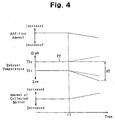
- the exhaust temperature control procedure is performed such that the second exhaust temperature Tho is adjusted to a certain value corresponding to the engine operational state. Therefore, when the NOx storage reduction catalyst 31 is clogged, the first exhaust temperature Thi and the second exhaust temperature Tho are varied as indicated by Fig. 4. In Fig. 4, the dotted lines indicate variations of the first and second exhaust temperatures Thi, Tho when the exhaust temperature control procedure is not performed (corresponding to the exhaust temperature variations indicated in Fig. 3).
- the second exhaust temperature Tho starts to rise gradually (as indicated by the corresponding dotted line in Fig. 4).
- the difference between the target exhaust temperature PT and the second exhaust temperature Tho becomes larger. Therefore, the amount of fuel injected by the injection nozzle 5 is decreased, such that the second exhaust temperature Tho is maintained at the target exhaust temperature PT corresponding to the current engine operational state.
- the first exhaust temperature Thi starts to decrease gradually.
- the first exhaust temperature Thi with the NOx storage reduction catalyst 31 clogged is lower than the first exhaust temperature Thi when the exhaust temperature control procedure is not performed (as indicated by the corresponding dotted line in Fig. 4). That is, even if the second exhaust temperature Tho is controlled to a substantially constant value through the exhaust temperature control procedure, the first exhaust temperature Thi is lowered in correspondence with the clogging degree of the NOx storage reduction catalyst 31. In other words, regardless of the exhaust temperature control procedure, the temperature difference ⁇ T is varied in correspondence with the clogging degree of the catalyst 31. Accordingly, even when the exhaust temperature control procedure is performed, the clogging degree of the NOx storage reduction catalyst 31 can be diagnosed based on the temperature difference ⁇ T.
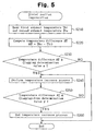
- Fig. 5 indicates the distal portion regeneration using the principles of such clogging state diagnosis.
- the procedure is repeatedly executed by the controller 25 at predetermined time intervals under the condition that fuel injection is performed through the injection nozzle 5.
- the first exhaust temperature Thi and the second exhaust temperature Tho are read by the controller 25 (in step S210).
- step S230 it is determined whether or not the temperature difference ⁇ T is equal to or greater than a clogging determination value ⁇ (in step S230).
- the clogging determination value ⁇ is used for determining whether or not the NOx storage reduction catalyst 31 is clogged and set to a predetermined value exceeding the temperature difference ⁇ T at which the catalyst 31 is not clogged. If it is determined that the temperature difference ⁇ T is smaller than the clogging determination value ⁇ (step S230: NO), the controller 25 determines that the current temperature difference ⁇ T is relatively small and thus the clogging degree of the NOx storage reduction catalyst 31 is relatively low, or the catalyst 31 is not clogged. The procedure is then suspended.
- step S230 determines that the current temperature difference ⁇ T is relatively great and thus the clogging degree of the NOx storage reduction catalyst 31 is relatively high, or the catalyst 31 is clogged. Therefore, in order to decrease the amount of collected matter in the catalyst 31, the cause of clogging, a temperature increase process of the NOx storage reduction catalyst 31 is executed (in step S240).
- the temperature increase process corresponds to a heating means. More specifically, the temperature increase process is performed in the following manner.
- a certain amount of fuel needed for regeneration of the distal portion of the catalyst 31 is injected by the injection nozzle 5.
- the fuel is then combusted in the NOx storage reduction catalyst 31.
- the injected fuel may promote clogging of the NOx storage reduction catalyst 31.
- the exhaust flow is decreased through adjustment of an engine control amount. More specifically, if the exhaust flow is decreased, the flow rate of the exhaust gas passing through the NOx storage reduction catalyst 31 is also reduced. This extends the time for purifying the exhaust gas in the catalyst 31.
- the reactive heat generated through purification is thus increased such that the NOx storage reduction catalyst 31 is heated effectively. Accordingly, adhesion of the injected fuel is suppressed and combustion of the fuel is promoted, ensuring the catalyst 31 to be heated. This burns out the collected matter in the NOx storage reduction catalyst 31 and reduces the amount of collected matter.
- the aforementioned adjustment of the engine control amount includes at least one of the followings: temporarily decreasing the opening degree of the throttle valve 16 for adjusting the intake air amount; temporarily decreasing the opening degree of the EGR valve 15 for adjusting the EGR amount; and temporarily decreasing the opening degree of the exhaust throttle valve 40 for adjusting the exhaust flow.
- the actual exhaust flow can be lowered.
- the clogging-free determination value ⁇ is used for determining whether or not the NOx storage reduction catalyst 31 is free from clogging.
- the clogging-free determination value ⁇ is set to a predetermined value corresponding to the temperature difference ⁇ T at which the NOx storage reduction catalyst 31 is not clogged.
- step S250 NO
- the procedure of step S240 is continued. In other words, the temperature increase process of the NOx storage reduction catalyst 31 is continuously performed.
- step S250 YES
- the temperature increase process is thus ended (in step S260) and the procedure of Fig. 5 is ended.
- the clogging state of the NOx storage reduction catalyst 31 is diagnosed and the clogging degree thereof is lowered.
- the first embodiment has the following advantages.
- the clogging state of the NOx storage reduction catalyst 31 is diagnosed based on the temperature difference ⁇ T between the first exhaust temperature Thi and the second exhaust temperature Tho.
- the first exhaust temperature Thi is lowered when the NOx storage reduction catalyst 31 is clogged, as compared to when the catalyst 31 is not clogged. It is thus determined that the clogging degree of the catalyst 31 becomes greater as the lowering amount of the first exhaust temperature Thi becomes larger. Therefore, in the second embodiment, the clogging state of the NOx storage reduction catalyst 31 is diagnosed based on the first exhaust temperature Thi, rather than the temperature difference ⁇ T. Only in this regard, the second embodiment is different from the first embodiment. The following description of the second embodiment will thus focus on the difference between the first and second embodiments.
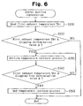
- Fig. 6 shows a distal portion regeneration of the second embodiment. Like the similar procedure of the first embodiment, the procedure of Fig. 6 is repeatedly executed by the controller 25 at predetermined time intervals under the condition that the fuel supply through the injection nozzle 5 is conducted.
- the first exhaust temperature Thi is read by the controller 25 (in step S310).
- a clogging determination value A is used for determining whether or not the NOx storage reduction catalyst 31 is clogged and is set to a predetermined value lower than the first exhaust temperature Thi at which the catalyst 31 is free from clogging. If the first exhaust temperature Thi is determined to be greater than the clogging determination value A (step S320: NO), it is determined that the current first exhaust temperature Thi is relatively high and thus the clogging degree of the NOx storage reduction catalyst 31 is relatively low. That is, it is determined that the NOx storage reduction catalyst 31 is free from clogging. The procedure is thus ended.
- step S320 YES
- the clogging determination value A YES
- the clogging-free determination value B is used for determining whether or not the NOx storage reduction catalyst 31 is free from clogging.
- the clogging-free determination value B is set to a predetermined value corresponding to the first exhaust temperature Thi at which the catalyst 31 is free from clogging.
- step S340 NO
- the procedure of step 330 is continued. In other words, the temperature increase process of the NOx storage reduction catalyst 31 is continuously carried out.
- step S340 YES
- the temperature increase process of the catalyst 31 is thus ended (in step S350) and the procedure of Fig. 6 is ended.
- the clogging state of the NOx storage reduction catalyst 31 is diagnosed and the clogging degree thereof is lowered.
- the clogging state of the NOx storage reduction catalyst 31 can be reliably diagnosed.
- the exhaust temperature control procedure of Fig. 2 may be omitted. Also in this case, as the clogging degree of the NOx storage reduction catalyst 31 becomes higher, the temperature difference ⁇ T becomes greater and the first exhaust temperature Thi becomes lower, as indicated by Fig. 4. It is thus possible to reliably diagnose the clogging state of the NOx storage reduction catalyst 31.
- the temperature increase process it is determined whether or not to perform the temperature increase process depending on the diagnosis of the clogging state of the exhaust purifying member.
- diagnosis may be used in different suitable manners. For example, in correspondence with the diagnosis that the exhaust purifying member is clogged, a warning lamp visible to the driver may be turned on. It is also possible to omit the temperature increase process while ensuring at least the clogging state diagnosis of the exhaust purifying member to be reliably carried out.
- the clogging degree of the NOx storage reduction catalyst 31 may be estimated based on the temperature difference ⁇ T. More specifically, as illustrated in Fig. 7, it may be determined that the clogging degree becomes higher as the temperature difference ⁇ T becomes greater.
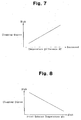
- the clogging degree of the NOx storage reduction catalyst 31 may be estimated based on the first exhaust temperature Thi. More specifically, as illustrated in Fig. 8, it may be determined that the clogging degree becomes higher as the first exhaust temperature Thi becomes lower.
- the heating amount of the catalyst 31 in the temperature increase process may be set. For example, as the estimated clogging degree becomes higher, the fuel supply for regenerating the distal portion of the catalyst 31 may be increased or the exhaust flow may be reduced. In this manner, the NOx storage reduction catalyst 31 may be efficiently heated, thus achieving the distal portion regeneration efficiently.
- the clogging determination value ⁇ and the clogging-free determination value ⁇ may be variably selected in correspondence with the engine operational state, for example, the engine load. In this case, even if the temperature difference ⁇ T at which the NOx storage reduction catalyst 31 is free from clogging is varied depending on the engine operational state, the clogging and clogging-free determination values ⁇ , ⁇ are varied in correspondence with such variation. The diagnosis accuracy of the clogging state of the catalyst 31 is thus improved.
- the first exhaust temperature Thi is varied also depending on the engine operational state. Therefore, in the second embodiment, the clogging state diagnosis of the NOx storage reduction catalyst 31 may be based on the difference between a reference temperature varied depending on the engine operational state and the first exhaust temperature Thi. For example, if the difference between the reference temperature and the first exhaust temperature Thi is equal to or greater than a predetermined value, it may be diagnosed that the NOx storage reduction catalyst 31 is clogged. In this case, the changing amount of the exhaust temperature caused by such clogging can be reliably acquired, making it possible to diagnose the clogging state of the catalyst 31 further reliably.
- the diagnosis is based on the fact that the clogging degree of the catalyst 31 is gradually heightened as the difference between the reference temperature and the first exhaust temperature Thi is increased, the clogging degree of the catalyst 31 is also reliably diagnosed.
- the clogging determination value A and the clogging-free determination value B may be varied according to the engine operational state, for example, the engine load. Even in this case, the same advantages as those of the above-described modification can be obtained.
- the number of the exhaust purifying members arranged in the exhaust passage 26, for example, in the catalytic device 30, may be changed as needed. If three or more exhaust purifying members are provided, the second temperature sensor 34 may be located at any desired position, as long as the second temperature sensor 34 is located downstream of the exhaust purifying member downstream of the first temperature sensor 33.
- the type of the exhaust purifying members arranged in the exhaust passage 26, for example, in the catalytic device 30, may be changed as needed.
- the DPNR catalyst 32 may be changed to an exhaust purifying member functioning only as a DPF (Diesel Particulate Filter), which is a PM filter for collecting particulate matter from exhaust gas.
- DPF Diesel Particulate Filter
- the arrangement of the exhaust purifying members with respect to the exhaust flow may be selected as desired.
- the DPNR catalyst 32 may be located upstream of the NOx storage reduction catalyst 31 in the catalytic device 30 with respect to the exhaust flow.
- This arrangement makes it possible to diagnose the clogging state of the DPNR catalyst 32.
- the aforementioned DPF may be arranged upstream of the NOx storage reduction catalyst 31 with respect to the exhaust flow. This arrangement makes it possible to diagnose the clogging state of the DPF.
- the diagnosis procedure that has been explained for the second embodiment may be applied to the case in which a single exhaust purifying member is deployed in the exhaust passage 26.
- engine fuel is employed as additive.
- any suitable additive may be employed.
- the injection nozzle 5 may be arranged at any desired position, as long as the injection nozzle 5 is located upstream of the catalytic device 30 with respect to the exhaust flow.
- the additive supply means may correspond to an injection timing control procedure for carrying out post injection by controlling the injection timing of the fuel injection nozzles, which supply fuel to the combustion chambers.
- the post injection is a fuel injection performed at a timing greatly retarded from the main injection (which is performed at timing close to the top dead center of compression and in correspondence with a fuel amount substantially corresponding to the engine load).
- some of the fuel corresponding to the post injection is combusted at a timing slightly retarded from that of the fuel corresponding to the main injection, which is performed prior to the post injection. This raises the exhaust temperature.
- the non-combusted remainder of the fuel corresponding to the post injection is introduced into the exhaust passage 26 together with exhaust gas.
- the fuel is then supplied to the exhaust purifying members as additive. Accordingly, additive is supplied to the exhaust purifying member through the post injection.
- the post injection and the fuel injection by the above-described additive supply mechanism may be executed at the same timings.
Landscapes
- Engineering & Computer Science (AREA)
- Chemical & Material Sciences (AREA)
- Combustion & Propulsion (AREA)
- Mechanical Engineering (AREA)
- General Engineering & Computer Science (AREA)
- Chemical Kinetics & Catalysis (AREA)
- Exhaust Gas After Treatment (AREA)
- Processes For Solid Components From Exhaust (AREA)
- Electrical Control Of Air Or Fuel Supplied To Internal-Combustion Engine (AREA)
- Filtering Of Dispersed Particles In Gases (AREA)
- Exhaust Gas Treatment By Means Of Catalyst (AREA)
Abstract


Description
- The present invention relates to an exhaust purifying apparatus for an internal combustion engine.
- Exhaust systems of some engines include an exhaust purifying member such as a carrier incorporating a NOx purifying catalyst that removes nitrogen oxide, a PM (particulate matter) filter for collecting particulate matter, and a DPNR catalyst formed by incorporating the NOx catalyst into a PM filter.
- In some cases, additive may be supplied to an exhaust purifying member for recovering purifying function of the exhaust purifying member. For example, as described in Japanese Patent No. 2722987, fuel is supplied, as the additive, to the PM filter incorporating a NOx catalyst. The NOx absorbed by the catalyst is thus reduced and released, such that the NOx removing function of the catalyst is recovered. Further, if the accumulation amount of the particulate matter collected by the PM filter is increased, pressure loss caused by the PM filter is increased. However, the fuel supplied to the PM filter as the additive burns out the particulate matter collected by the filter, so that the PM filter is regenerated.
- Although the additive supply is effective in recovering the function of the exhaust purifying member, it may lead to the following problems. That is, the additive supplied to'the exhaust purifying member is essentially evaporated and burned out through combustion or oxidization in the purifying member. However, if some of the additive is adhered to the exhaust purifying member without being combusted or oxidized, the adhered additive may function as a binder and adsorb particulate matter and the like, thus clogging the exhaust purifying member.
- Accordingly, it is an objective of the present invention to provide an exhaust purifying apparatus for an internal combustion engine capable of reliably diagnosing the clogging state of an exhaust purifying member.
- To achieve the foregoing and other objectives and in accordance with the purpose of the present invention, the invention provides an exhaust purifying apparatus for an internal combustion engine. The apparatus has a first exhaust purifying member, additive supply means, a first temperature sensor, and diagnosis means. The first exhaust purifying member is located in an exhaust passage. The additive supply means supplies additive to the first exhaust purifying member. The first temperature sensor detects the temperature of exhaust gas at an exit of the first exhaust purifying member. The diagnosis means diagnoses the state of clogging of the first exhaust purifying member based on an exhaust temperature that is detected by the first temperature sensor when the additive is supplied to the first exhaust purifying member.
- Other aspects and advantages of the invention will become apparent from the following description, taken in conjunction with the accompanying drawings, illustrating by way of example the principles of the invention.
- The invention, together with objects and advantages thereof, may best be understood by reference to the following description of the presently preferred embodiments together with the accompanying drawings in which:
- Fig. 1 is a view schematically showing an internal combustion engine and the vicinity thereof to which an exhaust purifying apparatus according to a first embodiment of the present invention is applied;
- Fig. 2 is a flowchart showing a procedure for controlling the exhaust temperature according to the first embodiment;
- Fig. 3 is a graph explaining the principles of diagnosis of the clogging state of an exhaust purifying member according to the first embodiment;
- Fig. 4 is a graph illustrating variations of the exhaust temperature, the amount of collected matter, and the amount of added fuel, when an exhaust temperature control procedure is performed;
- Fig. 5 is a flowchart showing distal portion regeneration according to the first embodiment;
- Fig. 6 is a flowchart showing distal portion regeneration according to a second embodiment of the present invention;
- Fig. 7 is a graph showing temperature difference between the first and second exhaust temperatures versus clogging degree of an exhaust purifying member in a modification of the first embodiment; and
- Fig. 8 is a graph showing first exhaust temperature versus clogging degree of an exhaust purifying member in a modification of the second embodiment.
-
- An exhaust purifying apparatus for an engine according to a first embodiment of the present invention will now be described with reference to Figs. 1 to 5.
- Fig. 1 schematically shows a
diesel engine 1, acontroller 25 of thediesel engine 1, and the vicinity of theengine 1. Theengine 1 includes a plurality ofcylinders # 1, #2, #3, #4. A plurality offuel injection valves cylinder head 2. Each of thefuel injection valves 4a to 4b injects fuel into a corresponding one of the combustion chambers defined by thecylinders # 1 to #4. Further, a plurality of intake ports andexhaust ports cylinder head 2 in correspondence with thecylinders # 1 to #4. Each of the intake ports introduces the ambient air into thecorresponding cylinder # 1 to #4. Each of theexhaust ports 6a to 6d discharges combustion gas from thecorresponding cylinder # 1 to #4. - The
fuel injection valves 4a to 4d are connected to a common rail 9 in which a high-pressure fuel is retained. The common rail 9 is connected to asupply pump 10. Thesupply pump 10 draws fuel from a fuel tank and supplies the high-pressure fuel to the common rail 9. The high-pressure fuel is then injected into thecylinders # 1 to #4 by theinjection valves 4a to 4b, when thevalves 4a to 4b are opened. - The intake ports are connected to an
intake manifold 7. Theintake manifold 7 is connected to anintake passage 3. Athrottle valve 16 is disposed in theintake passage 3 for adjusting the intake air amount. Theexhaust ports 6a to 6d are connected to anexhaust manifold 8. Theexhaust manifold 8 is connected to anexhaust passage 26. - A
catalytic device 30 is provided in theexhaust passage 26 for purifying exhaust gas. Two exhaust purifying members are arranged in series in thecatalytic device 30. The exhaust purifying members include a first exhaust purifying member and a second exhaust purifying member. The first exhaust purifying member corresponds to a NOxstorage reduction catalyst 31, which is provided at a relatively upstream position with respect to the exhaust flow, for removing NOx from exhaust gas. The second exhaust purifying member corresponds to a Diesel Particulate-NOx Reduction system (DPNR)catalyst 32, which is located downstream of thecatalyst 31 with respect to the exhaust flow, for reducing the amount of the particulate matter or NOx released from the exhaust into the air. TheDPNR catalyst 32 is formed by incorporating a NOx storage reduction catalyst into a porous ceramic structure. The particulate matter contained in the exhaust gas is collected by theDPNR catalyst 32 when passing through a porous wall of thecatalyst 32. Further, when the air-fuel ratio of exhaust gas is lean, NOx in the exhaust is stored in the NOxstorage reduction catalyst 31. In contrast, if the air-fuel ratio of the exhaust gas is rich, the stored NOx is reduced and released by substances such as HC and CO. - The
engine 1 also includes an EGR device. The EGR device introduces some of the exhaust gas into the intake air, thus lowering the combustion temperature in the cylinders. This reduces the generation amount of NOx. The EGR device is configured by an EGR passage 13 connecting theintake passage 3 to theexhaust passage 26, anEGR valve 15 disposed in the EGR passage 13, anEGR cooler 14, and the like. By adjusting the opening degree of theEGR valve 15, the reflux amount of the exhaust flowing from theexhaust passage 26 to theintake passage 3, which is the EGR amount, is controlled. The EGRcooler 14 cools the exhaust gas flowing in the EGR passage 13. TheEGR valve 15 is provided with an EGR valveopening degree sensor 22, which detects the opening degree of theEGR valve 15, or an EGR valve opening degree EA. - The
engine 1 also has a turbocharger 11 for supercharging intake air to each of thecylinders # 1 to #4, using exhaust pressure. Anintercooler 18 is disposed in a section of theintake passage 3 between an intake turbine and thethrottle valve 16. Theintercooler 18 cools the intake air warmed through supercharging by the turbocharger 11. - An
exhaust throttle valve 40 is provided in a section of theexhaust passage 26 downstream of thecatalytic device 30 with respect to the exhaust flow. Theexhaust throttle valve 40 adjusts the flow rate of exhaust gas in theexhaust passage 26. As the opening degree of theexhaust throttle valve 40 becomes smaller, the flow rate of exhaust gas also becomes smaller. - Various sensors are installed in the
engine 1 for detecting the operational state of theengine 1. For example, an airflow meter 19 detects an intake air amount GA in theintake passage 3. A throttleopening degree sensor 20 detects the opening degree of thethrottle valve 16, or a throttle opening degree TA. Afirst temperature sensor 33 is provided downstream of the NOxstorage reduction catalyst 31 with respect to the exhaust flow for detecting a first exhaust temperature Thi. The first exhaust temperature Thi corresponds to the exhaust temperature at the exit of the NOxstorage reduction catalyst 31. Asecond temperature sensor 34 is disposed downstream of theDPNR catalyst 32, the other exhaust purifying member located downstream of the NOxstorage reduction catalyst 31, for detecting a second exhaust temperature Tho. The second exhaust temperature Tho corresponds to the exhaust temperature at the exit of theDPNR catalyst 32. Anengine speed sensor 23 detects the rotation speed of a crankshaft, or an engine speed NE. Anaccelerator pedal sensor 24 detects the depression amount of an accelerator pedal, or a pedal depression degree ACCP. An air-fuel ratio sensor 21 detects an air-fuel ratio λ of exhaust. - The outputs of these sensors are inputted to the
controller 25. Thecontroller 25 is configured mainly by a microcomputer including a central processing unit (CPU), a read only memory (ROM), a random access memory (RAM), a timer-counter, an input interface, and an output interface. The ROM pre-stores various programs and maps. The RAM temporarily stores computation results obtained by the CPU. Thecontroller 25 performs various control procedures of theengine 1, including those for the fuel injection amount and injection timing of thefuel injection valves 4a to 4d, the displacement pressure of thesupply pump 10, the actuation amount of anactuator 17 selectively opening and closing thethrottle valve 16, the opening degree of theEGR valve 15, and actuation of theexhaust throttle valve 40. - Further, an
injection nozzle 5 is secured to thecylinder head 2 and forms an additive supply mechanism for supplying fuel to the NOxstorage reduction catalyst 31 and theDPNR catalyst 32. Theinjection nozzle 5 injects fuel, as additive, to anexhaust port 6a of thefirst cylinder # 1. The injected fuel reaches the NOxstorage reduction catalyst 31 and theDPNR catalyst 32, together with exhaust gas. Theinjection nozzle 5 and thesupply pump 10 are connected to each other through afuel supply pipe 27, such that gas oil, the fuel, is supplied to theinjection nozzle 5. Theinjection nozzle 5 is configured identical to thefuel injection valves 4a to 4d. Thecontroller 25 controls the injection amount and injection timing of theinjection nozzle 5. - In the first embodiment, the additive supply mechanism supplies fuel to the NOx
storage reduction catalyst 31 and theDPNR catalyst 32 for the following reasons: - A. In diesel engines, the exhaust air-fuel ratio is
normally lean. Thus, before the storage amount of NOx in the
NOx
storage reduction catalyst 31 and theDPNR catalyst 32 reaches a limit, the exhaust air-fuel ratio must be enriched for reducing and releasing the NOx stored in thecatalysts controller 25 performs a NOx reduction procedure by supplying fuel through theinjection nozzle 5. The fuel functions as a NOx reducing agent when received by the NOxstorage reduction catalyst 31 and theDPNR catalyst 32. Further, the fuel consumes oxygen as combusted in the NOxstorage reduction catalyst 31 and theDPNR catalyst 32, such that the exhaust fuel-air ratio is enriched. The NOx reduction procedure maintains the NOx removing functions of thecatalysts - B. As the accumulation amount of particulate matter in
the
DPNR catalyst 32 becomes larger, the pressure loss caused by theDPNR catalyst 32 becomes greater. Thus, before the pressure loss becomes excessively large and affects the engine operational state adversely, the accumulated particulate matter must be decreased, or a regeneration of theDPNR catalyst 32 must be performed. Accordingly, when the accumulation amount of particulate matter, as estimated based on the engine operational state or the difference between an upstream exhaust pressure and a downstream exhaust pressure of thecatalytic device 30, reaches a predetermined limit value, thecontroller 25 performs the regeneration of theDPNR catalyst 32 by supplying fuel through theinjection nozzle 5. The fuel is combusted when reaching theDPNR catalyst 32, such that the particulate matter is ignited and eventually burned out. In other words, the fuel functions as a promoter for burning the particulate matter. The regeneration of theDPNR catalyst 32 thus decreases the accumulation amount of particulate matter in theDPNR catalyst 32. - C. The NOx storage reduction catalyst also absorbs SOx
(sulfur oxides) generated from sulfur, which is originated in
fuel and lubricant oil. Since the storage capacity of the NOx
storage reduction catalyst is limited, the actual amount of
NOx allowed to be stored in the catalyst may be reduced if
the absorption amount of SOx increases. In other words, the
NOx removing function of the NOx storage reduction catalyst
is lowered due to so-called SOx poisoning. However, it is
known that SOx absorbed by the NOx storage reduction catalyst
is released from the catalyst in a high-temperature reducing
atmosphere of approximately 600 degrees Celsius. It is thus
possible to reduce the amount of SOx absorbed by the NOx
storage reduction catalyst under this condition. Accordingly,
when the absorption amount of SOx, as estimated based on the
engine operation sate or the like, reaches a predetermined
limit value, the
controller 25 executes a SOx poisoning recovery procedure by injecting fuel through theinjection nozzle 5. The fuel is combusted in the NOxstorage reduction catalyst 31 and theDPNR catalyst 32, generating heat for heating thecatalysts catalysts catalysts catalysts -
- The fuel is supplied to the NOx
storage reduction catalyst 31 and theDPNR catalyst 32 for the above reasons A to C. - The NOx
storage reduction catalyst 31 or theDPNR catalyst 32 may be damaged when heated excessively. Particularly, since theDPNR catalyst 32 receives the exhaust gas heated in the NOxstorage reduction catalyst 31, the temperature of theDPNR catalyst 32 tends to become greater than that of the NOxstorage reduction catalyst 31. Therefore, if the exhaust temperature is controlled to a target value for suppressing excessive heating of theDPNR catalyst 32, the NOxstorage reduction catalyst 31 is also prevented from being heated excessively. - Since the additive is combusted in the
DPNR catalyst 32, excessive heating of theDPNR catalyst 32 cannot be suppressed by controlling the exhaust temperature at a position upstream of theDPNR catalyst 32 with respect to the exhaust flow (the first exhaust temperature Thi). In contrast, if the exhaust temperature at the exit of the DPNR catalyst 32 (the second exhaust temperature Tho) is controlled, a temperature rise caused by the additive combustion in thecatalyst 32 is taken into account of the control procedure. The temperature of theDPNR catalyst 32 is thus adjusted to a value close to the target. In the first embodiment, by adjusting the amount of the fuel supplied by theinjection nozzle 5, the exhaust temperature at a position downstream of theDPNR catalyst 32, which is the second exhaust temperature Tho detected by thesecond temperature sensor 34, is controlled to a target exhaust temperature PT. - Fig. 2 shows a procedure for controlling the exhaust temperature executed by the
controller 25. The procedure corresponds to exhaust temperature control means. - First, the second exhaust temperature Tho is read by the controller 25 (in step S110). Next, based on the difference between the target exhaust temperature PT and the second exhaust temperature Tho, the amount of the fuel to be supplied by the
injection nozzle 5 is set (in step S120). The procedure is then suspended. The target exhaust temperature PT corresponds to a temperature at which the exhaust purifying performance of theDPNR catalyst 32 is maintained and excessive heating of thecatalyst 32 is suppressed. The target exhaust temperature PT is set in correspondence with the engine operational state, which is, for example, the engine load correlated with the exhaust temperature. Further, as the difference between the target exhaust temperature PT and the second exhaust temperature Tho becomes larger, or the second exhaust temperature Tho becomes higher than the target exhaust temperature PT, the fuel addition amount becomes smaller. By enabling theinjection nozzle 5 to inject fuel in correspondence with the set fuel addition amount, the exhaust temperature downstream of theDPNR catalyst 32 is controlled to the target exhaust temperature PT. In other words, the temperature of theDPNR catalyst 32 is maintained at a predetermined value in correspondence with the engine operational state. - However, the fuel supply may cause the following problem. The additive supplied to the exhaust purifying members including the NOx
storage reduction catalyst 31 and theDPNR catalyst 32 are essentially evaporated and burned out through combustion in the exhaust purifying members and oxidization. However, if some of the additive is adhered to the exhaust purifying members without being burned out or oxidized, the adhered additive may become a binder and adsorb 'the particulate matter or the like, clogging the exhaust purifying members. - Also, although the exhaust purifying members including the NOx
storage reduction catalyst 31 and theDPNR catalyst 32 are heated by the heat generated through the additive oxidization and combustion in the exhaust purifying members, the temperature distribution in each of the exhaust purifying members is non-uniform. More specifically, the temperature of the NOxstorage reduction catalyst 31 or that of theDPNR catalyst 32 becomes higher toward a downstream side of the exhaust flow, due to the heat generated through the additive oxidization and combustion. That is, the temperature of the NOxstorage reduction catalyst 31 or that of theDPNR catalyst 32 becomes lower toward an upstream side of the exhaust flow. Thus, the fuel adhered to a distal, upstream portion of each exhaust purifying member tends to be hardly heated to the temperature sufficiently high for causing the. fuel to be oxidized or combusted. In some cases, the additive remains adhered to the'distal portion of the fuel purifying member and becomes a binder. The additive thus adsorbs particulate matter from exhaust, clogging the NOxstorage reduction catalyst 31 or theDPNR catalyst 32. - Further, in the first embodiment, the NOx
storage reduction catalyst 31 is arranged upstream of theDPNR catalyst 32 with respect to the exhaust flow, clogging may occur particularly at a distal portion of the NOxstorage reduction catalyst 31. The first embodiment thus includes diagnosis means for diagnosing the clogging state of the NOxstorage reduction catalyst 31. More specifically, distal portion regeneration is performed for diagnosing the clogging state of the NOxstorage reduction catalyst 31 and lowering the clogging degree. - Fig. 3 shows the principles of such diagnosis. In other words, Fig. 3 shows variation of the first exhaust temperature Thi and that of the second exhaust temperature Tho when the fuel injection is performed through the
injection nozzle 5 with the engine operated in a certain operational state. - If the NOx
storage reduction catalyst 31 is free from collected matter such as deposit, or free from clogging, the fuel injected by theinjection nozzle 5 is sent to and combusted in the NOxstorage reduction catalyst 31 together with exhaust gas. The exhaust temperature at the exit of the NOxstorage reduction catalyst 31, or the first exhaust temperature Thi detected by thefirst temperature sensor 33, is thus heated. The exhaust gas exiting the NOxstorage reduction catalyst 31 is further heated through exhaust purification of theDPNR catalyst 32 when passing through thecatalyst 32. The second exhaust temperature Tho detected by thesecond temperature sensor 34 is thus higher than the first exhaust temperature Thi. - If the amount of collected matter in the NOx
storage reduction catalyst 31 starts to increase at time t1, the clogging degree of thecatalyst 31 starts to become larger. This decreases the communication area for exhaust gas in the NOxstorage reduction catalyst 31. Some of the fuel thus exits thecatalyst 31 without being combusted. Therefore, as the clogging degree of the NOxstorage reduction catalyst 31 becomes larger, the exhaust temperature at the exit of the catalyst 31 (the first exhaust temperature Thi) becomes lower. However, the fuel exiting thecatalyst 31 without being combusted is combusted when passing through theDPNR catalyst 32. Thus, as the clogging degree of the NOxstorage reduction catalyst 31 becomes larger, the exhaust temperature downstream of the DPNR catalyst 32 (the second exhaust temperature Tho), which is located downstream of thecatalyst 31, becomes higher. Accordingly, if the NOxstorage reduction catalyst 31 is clogged, a temperature difference ΔT between the exhaust temperature downstream of the catalyst 31 (the first exhaust temperature Thi), or the exhaust temperature upstream of theDPNR catalyst 32, and the exhaust temperature downstream of the DPNR catalyst 32 (the second.exhaust temperature Tho) becomes greater. It is thus possible to use the temperature difference ΔT as an indicator of the clogging degree of the NOxstorage reduction catalyst 31. - Even if the exhaust temperature in the
exhaust passage 26 is varied depending on the engine operational state, the second exhaust temperature Tho changes in a manner corresponding to the first exhaust temperature Thi. Thus, the temperature difference ΔT is essentially unaffected by the variation of the exhaust temperature depending on the engine operational state. Accordingly, by using the temperature difference ΔT as the indicator of the clogging degree of the NOxstorage reduction catalyst 31, the clogging state of thecatalyst 31 is diagnosed reliably, regardless of the exhaust temperature variation in theexhaust passage 26 depending on the engine operational state. - In the first embodiment, the exhaust temperature control procedure is performed such that the second exhaust temperature Tho is adjusted to a certain value corresponding to the engine operational state. Therefore, when the NOx
storage reduction catalyst 31 is clogged, the first exhaust temperature Thi and the second exhaust temperature Tho are varied as indicated by Fig. 4. In Fig. 4, the dotted lines indicate variations of the first and second exhaust temperatures Thi, Tho when the exhaust temperature control procedure is not performed (corresponding to the exhaust temperature variations indicated in Fig. 3). - As has been described, when the amount of collected matter in the NOx
storage reduction catalyst 31 starts to increase at time t1 such that the clogging degree of thecatalyst 31 becomes greater, the second exhaust temperature Tho starts to rise gradually (as indicated by the corresponding dotted line in Fig. 4). As the second exhaust temperature Tho becomes higher, the difference between the target exhaust temperature PT and the second exhaust temperature Tho becomes larger. Therefore, the amount of fuel injected by theinjection nozzle 5 is decreased, such that the second exhaust temperature Tho is maintained at the target exhaust temperature PT corresponding to the current engine operational state. In contrast, when the amount of collected matter in the NOxstorage reduction catalyst 31 starts to increase at time t1 such that the clogging degree of thecatalyst 31 becomes greater, the first exhaust temperature Thi starts to decrease gradually. However, since the fuel injection amount is reduced as aforementioned, the amount of the fuel combusted in the NOxstorage reduction catalyst 31 is also decreased. The heat generated through the fuel combustion is thus reduced. Therefore, the first exhaust temperature Thi with the NOxstorage reduction catalyst 31 clogged is lower than the first exhaust temperature Thi when the exhaust temperature control procedure is not performed (as indicated by the corresponding dotted line in Fig. 4). That is, even if the second exhaust temperature Tho is controlled to a substantially constant value through the exhaust temperature control procedure, the first exhaust temperature Thi is lowered in correspondence with the clogging degree of the NOxstorage reduction catalyst 31. In other words, regardless of the exhaust temperature control procedure, the temperature difference ΔT is varied in correspondence with the clogging degree of thecatalyst 31. Accordingly, even when the exhaust temperature control procedure is performed, the clogging degree of the NOxstorage reduction catalyst 31 can be diagnosed based on the temperature difference ΔT. - Fig. 5 indicates the distal portion regeneration using the principles of such clogging state diagnosis. The procedure is repeatedly executed by the
controller 25 at predetermined time intervals under the condition that fuel injection is performed through theinjection nozzle 5. - First, the first exhaust temperature Thi and the second exhaust temperature Tho are read by the controller 25 (in step S210). The temperature difference ΔT between the first exhaust temperature Thi and the second exhaust temperature Tho (ΔT = Tho - Thi) is then computed (in step S220).
- Subsequently, it is determined whether or not the temperature difference ΔT is equal to or greater than a clogging determination value α (in step S230). The clogging determination value α is used for determining whether or not the NOx
storage reduction catalyst 31 is clogged and set to a predetermined value exceeding the temperature difference ΔT at which thecatalyst 31 is not clogged. If it is determined that the temperature difference ΔT is smaller than the clogging determination value α (step S230: NO), thecontroller 25 determines that the current temperature difference ΔT is relatively small and thus the clogging degree of the NOxstorage reduction catalyst 31 is relatively low, or thecatalyst 31 is not clogged. The procedure is then suspended. - In contrast, if it is determined that the temperature difference ΔT is equal to or greater than the clogging determination value α (step S230: YES), the
controller 25 determines that the current temperature difference ΔT is relatively great and thus the clogging degree of the NOxstorage reduction catalyst 31 is relatively high, or thecatalyst 31 is clogged. Therefore, in order to decrease the amount of collected matter in thecatalyst 31, the cause of clogging, a temperature increase process of the NOxstorage reduction catalyst 31 is executed (in step S240). The temperature increase process corresponds to a heating means. More specifically, the temperature increase process is performed in the following manner. - First, a certain amount of fuel needed for regeneration of the distal portion of the
catalyst 31 is injected by theinjection nozzle 5. The fuel is then combusted in the NOxstorage reduction catalyst 31. At this stage, if the temperature of thecatalyst 31 is excessively low, the injected fuel may promote clogging of the NOxstorage reduction catalyst 31. Thus, the exhaust flow is decreased through adjustment of an engine control amount. More specifically, if the exhaust flow is decreased, the flow rate of the exhaust gas passing through the NOxstorage reduction catalyst 31 is also reduced. This extends the time for purifying the exhaust gas in thecatalyst 31. The reactive heat generated through purification is thus increased such that the NOxstorage reduction catalyst 31 is heated effectively. Accordingly, adhesion of the injected fuel is suppressed and combustion of the fuel is promoted, ensuring thecatalyst 31 to be heated. This burns out the collected matter in the NOxstorage reduction catalyst 31 and reduces the amount of collected matter. - Further, the aforementioned adjustment of the engine control amount includes at least one of the followings: temporarily decreasing the opening degree of the
throttle valve 16 for adjusting the intake air amount; temporarily decreasing the opening degree of theEGR valve 15 for adjusting the EGR amount; and temporarily decreasing the opening degree of theexhaust throttle valve 40 for adjusting the exhaust flow. Through such adjustment of the engine control amount, the actual exhaust flow can be lowered. - Next, it is determined whether or not the temperature difference ΔT is equal to or smaller than a clogging-free determination value β (in step S250). The clogging-free determination value β is used for determining whether or not the NOx
storage reduction catalyst 31 is free from clogging. In the first embodiment, the clogging-free determination value β is set to a predetermined value corresponding to the temperature difference ΔT at which the NOxstorage reduction catalyst 31 is not clogged. By setting the clogging-free determination value β to a value smaller than at least the clogging determination value α, at least lowering of the clogging degree can be diagnosed. - If the temperature difference ΔT is determined to be larger than the clogging-free determination value β (step S250: NO), the procedure of step S240 is continued. In other words, the temperature increase process of the NOx
storage reduction catalyst 31 is continuously performed. - In contrast, if the temperature difference ΔT is determined to be equal to or smaller than the clogging-free determination value β (step S250: YES), it is determined that the amount of collected matter in the NOx
storage reduction catalyst 31 has been reduced sufficiently by the temperature increase process, or thecatalyst 31 has been freed from clogging. The temperature increase process is thus ended (in step S260) and the procedure of Fig. 5 is ended. - In accordance with the above-described distal portion regeneration, the clogging state of the NOx
storage reduction catalyst 31 is diagnosed and the clogging degree thereof is lowered. - The first embodiment has the following advantages.
- (1) In response to the fuel supply, the temperature
difference ΔT between the first exhaust temperature Thi, the
exhaust temperature at the exit of the NOx
storage reduction catalyst 31, and the second exhaust temperature Tho, the exhaust temperature at the exit of theDPNR catalyst 32 located downstream of thecatalyst 31, is computed. The temperature difference ΔT is used as the indicator of the clogging degree of the NOxstorage reduction catalyst 31. It is thus possible to reliably diagnose the clogging state of thecatalyst 31. Even if the exhaust temperature in theexhaust passage 26 is varied depending on the engine operational state, the second exhaust temperature Tho changes in correspondence with the first exhaust temperature Thi. The temperature difference ΔT is thus hardly affected by the variation of the exhaust temperature depending on the engine operational state. Accordingly, by diagnosing the clogging state of the NOxstorage reduction catalyst 31 based on the temperature difference ΔT, the diagnosis is reliably accomplished regardless of such variation of the exhaust temperature. - (2) The amount of the fuel injected by the
injection nozzle 5 is adjusted such that the second exhaust temperature Tho corresponds to the target exhaust temperature PT. The temperature of theDPNR catalyst 32 is thus reliably controlled. - (3) As the second exhaust temperature Tho becomes
higher than the target exhaust temperature PT, the fuel
injection amount is decreased. Accordingly, excessive heating
of the
DPNR catalyst 32 is reliably suppressed. - (4) If it is determined that the NOx
storage reduction catalyst 31 is clogged based on the above-described diagnosis, the temperature increase process of thecatalyst 31 is executed. This lowers the clogging degree of the NOxstorage reduction catalyst 31. Since the clogging state of the NOxstorage reduction catalyst 31 is reliably diagnosed in the first embodiment, determination whether or not to perform the temperature increase process is carried out in an appropriate manner. - (5) In the temperature increase process, at least one
of the opening degree of the
throttle valve 16 for adjusting' the intake air amount, the opening degree of the EGR (exhaust gas recirculation)valve 15 for adjusting the EGR amount, and the opening degree of theexhaust throttle valve 40 is adjusted as the engine control amount, such that the exhaust flow rate is reduced. This extends the time for purifying the exhaust gas in the NOxstorage reduction catalyst 31, and the reactive heat generated through purification is increased. The NOxstorage reduction catalyst 31 is thus heated effectively. - (6) The fuel is injected by the additive supply
mechanism disposed in the
exhaust passage 26, which is theinjection nozzle 5. The fuel is thus reliably supplied to the NOxstorage reduction catalyst 31 and theDPNR catalyst 32 as the additive. - (7) The
DPNR catalyst 32 functions as a filter for collecting particulate matter from exhaust gas, as well as a NOx catalyst for removing NOx in the exhaust gas. Thus, in many cases, additive is added to theDPNR catalyst 32 in order to burn out the collected particulate matter or reducing and releasing the absorbed NOx and the like. Since the NOxstorage reduction catalyst 31 is located upstream of theDPNR catalyst 32 with respect to the exhaust flow and the temperature of the NOxstorage reduction catalyst 31 is lower than that of theDPNR catalyst 32, the NOxstorage reduction catalyst 31 is susceptive to clogging. However, in the first embodiment, the clogging state of thecatalyst 31 is reliably diagnosed and the clogging degree thereof is reduced by the temperature increase process. -
- An exhaust purifying apparatus for an engine according to a second embodiment of the present invention will now be described with reference to Fig. 6.
- In the first embodiment, the clogging state of the NOx
storage reduction catalyst 31 is diagnosed based on the temperature difference ΔT between the first exhaust temperature Thi and the second exhaust temperature Tho. As has been described, the first exhaust temperature Thi is lowered when the NOxstorage reduction catalyst 31 is clogged, as compared to when thecatalyst 31 is not clogged. It is thus determined that the clogging degree of thecatalyst 31 becomes greater as the lowering amount of the first exhaust temperature Thi becomes larger. Therefore, in the second embodiment, the clogging state of the NOxstorage reduction catalyst 31 is diagnosed based on the first exhaust temperature Thi, rather than the temperature difference ΔT. Only in this regard, the second embodiment is different from the first embodiment. The following description of the second embodiment will thus focus on the difference between the first and second embodiments. - Fig. 6 shows a distal portion regeneration of the second embodiment. Like the similar procedure of the first embodiment, the procedure of Fig. 6 is repeatedly executed by the
controller 25 at predetermined time intervals under the condition that the fuel supply through theinjection nozzle 5 is conducted. - First, the first exhaust temperature Thi is read by the controller 25 (in step S310). Next, it is determined whether or not the first exhaust temperature Thi is equal to or lower than a clogging determination value A (in step S320). The clogging determination value A is used for determining whether or not the NOx
storage reduction catalyst 31 is clogged and is set to a predetermined value lower than the first exhaust temperature Thi at which thecatalyst 31 is free from clogging. If the first exhaust temperature Thi is determined to be greater than the clogging determination value A (step S320: NO), it is determined that the current first exhaust temperature Thi is relatively high and thus the clogging degree of the NOxstorage reduction catalyst 31 is relatively low. That is, it is determined that the NOxstorage reduction catalyst 31 is free from clogging. The procedure is thus ended. - In contrast, if the first exhaust temperature Thi is determined to be equal to or lower than the clogging determination value A (step S320: YES), it is determined that the current first exhaust temperature Thi is relatively low and thus the clogging degree of the NOx
storage reduction catalyst 31 is relatively high. That is, it is diagnosed that the NOxstorage reduction catalyst 31 is clogged. Therefore, in order to reduce the amount of collected matter, the cause of clogging of thecatalyst 31, a temperature increase process of the NOxstorage reduction catalyst 31 is executed (in step S330). The temperature increase process is carried out in the same manner as the temperature increase process in step S240 of the distal portion regeneration of the first embodiment. - Subsequently, it is determined whether or not the first exhaust temperature Thi is equal to or higher than a clogging-free determination value B (in step S340). The clogging-free determination value B is used for determining whether or not the NOx
storage reduction catalyst 31 is free from clogging. In the second embodiment, the clogging-free determination value B is set to a predetermined value corresponding to the first exhaust temperature Thi at which thecatalyst 31 is free from clogging. By setting.the clogging-free determination value B to a value larger than at least the clogging determination value A, at least lowering of the clogging degree can be diagnosed. - If the first exhaust temperature Thi is lower than the clogging-free determination value B (step S340: NO), the procedure of
step 330 is continued. In other words, the temperature increase process of the NOxstorage reduction catalyst 31 is continuously carried out. - In contrast, if the first exhaust temperature Thi is determined to be equal to or higher than the clogging-free determination value B (step S340: YES), it is diagnosed that the amount of collected matter in the NOx
storage reduction catalyst 31 has been sufficiently decreased, or thecatalyst 31 has been freed from clogging. The temperature increase process of thecatalyst 31 is thus ended (in step S350) and the procedure of Fig. 6 is ended. - In accordance with the above-described distal portion regeneration, the clogging state of the NOx
storage reduction catalyst 31 is diagnosed and the clogging degree thereof is lowered. - Further, in a similar manner, it is possible to diagnose the clogging state of the
DPNR catalyst 32 and lower the clogging degree thereof based on the second exhaust temperature Tho. - Also in the second embodiment, the clogging state of the NOx
storage reduction catalyst 31 can be reliably diagnosed. - The illustrated embodiments may be modified as follows.
- In each of the embodiments, the exhaust temperature control procedure of Fig. 2 may be omitted. Also in this case, as the clogging degree of the NOx
storage reduction catalyst 31 becomes higher, the temperature difference ΔT becomes greater and the first exhaust temperature Thi becomes lower, as indicated by Fig. 4. It is thus possible to reliably diagnose the clogging state of the NOxstorage reduction catalyst 31. - In each of the illustrated embodiments, it is determined whether or not to perform the temperature increase process depending on the diagnosis of the clogging state of the exhaust purifying member. Such diagnosis may be used in different suitable manners. For example, in correspondence with the diagnosis that the exhaust purifying member is clogged, a warning lamp visible to the driver may be turned on. It is also possible to omit the temperature increase process while ensuring at least the clogging state diagnosis of the exhaust purifying member to be reliably carried out.
- In the first embodiment, the clogging degree of the NOx
storage reduction catalyst 31 may be estimated based on the temperature difference ΔT. More specifically, as illustrated in Fig. 7, it may be determined that the clogging degree becomes higher as the temperature difference ΔT becomes greater. - In the second embodiment, the clogging degree of the NOx
storage reduction catalyst 31 may be estimated based on the first exhaust temperature Thi. More specifically, as illustrated in Fig. 8, it may be determined that the clogging degree becomes higher as the first exhaust temperature Thi becomes lower. - As has been described, it is possible to estimate the clogging degree of the NOx
storage reduction catalyst 31 in the first and second embodiments. In correspondence with the estimation, the heating amount of thecatalyst 31 in the temperature increase process may be set. For example, as the estimated clogging degree becomes higher, the fuel supply for regenerating the distal portion of thecatalyst 31 may be increased or the exhaust flow may be reduced. In this manner, the NOxstorage reduction catalyst 31 may be efficiently heated, thus achieving the distal portion regeneration efficiently. - In the first embodiment, the clogging determination value α and the clogging-free determination value β may be variably selected in correspondence with the engine operational state, for example, the engine load. In this case, even if the temperature difference ΔT at which the NOx
storage reduction catalyst 31 is free from clogging is varied depending on the engine operational state, the clogging and clogging-free determination values α, β are varied in correspondence with such variation. The diagnosis accuracy of the clogging state of thecatalyst 31 is thus improved. - The first exhaust temperature Thi is varied also depending on the engine operational state. Therefore, in the second embodiment, the clogging state diagnosis of the NOx
storage reduction catalyst 31 may be based on the difference between a reference temperature varied depending on the engine operational state and the first exhaust temperature Thi. For example, if the difference between the reference temperature and the first exhaust temperature Thi is equal to or greater than a predetermined value, it may be diagnosed that the NOxstorage reduction catalyst 31 is clogged. In this case, the changing amount of the exhaust temperature caused by such clogging can be reliably acquired, making it possible to diagnose the clogging state of thecatalyst 31 further reliably. - Further, if the diagnosis is based on the fact that the clogging degree of the
catalyst 31 is gradually heightened as the difference between the reference temperature and the first exhaust temperature Thi is increased, the clogging degree of thecatalyst 31 is also reliably diagnosed. - Also, in the second embodiment, the clogging determination value A and the clogging-free determination value B may be varied according to the engine operational state, for example, the engine load. Even in this case, the same advantages as those of the above-described modification can be obtained.
- In the illustrated embodiments and the modifications thereof, the number of the exhaust purifying members arranged in the
exhaust passage 26, for example, in thecatalytic device 30, may be changed as needed. If three or more exhaust purifying members are provided, thesecond temperature sensor 34 may be located at any desired position, as long as thesecond temperature sensor 34 is located downstream of the exhaust purifying member downstream of thefirst temperature sensor 33. - In the illustrated embodiments and the modifications thereof, the type of the exhaust purifying members arranged in the
exhaust passage 26, for example, in thecatalytic device 30, may be changed as needed. For example, theDPNR catalyst 32 may be changed to an exhaust purifying member functioning only as a DPF (Diesel Particulate Filter), which is a PM filter for collecting particulate matter from exhaust gas. Further, if different types of exhaust purifying members are disposed in thecatalytic device 30, the arrangement of the exhaust purifying members with respect to the exhaust flow may be selected as desired. For example, in the first embodiment, theDPNR catalyst 32 may be located upstream of the NOxstorage reduction catalyst 31 in thecatalytic device 30 with respect to the exhaust flow. This arrangement makes it possible to diagnose the clogging state of theDPNR catalyst 32. Alternatively, the aforementioned DPF may be arranged upstream of the NOxstorage reduction catalyst 31 with respect to the exhaust flow. This arrangement makes it possible to diagnose the clogging state of the DPF. - The diagnosis procedure that has been explained for the second embodiment may be applied to the case in which a single exhaust purifying member is deployed in the
exhaust passage 26. - In the illustrated embodiments and the modifications thereof, engine fuel is employed as additive. However, as long as the same operation can be obtained, any suitable additive may be employed.
- In the illustrated embodiments and the modifications thereof, the
injection nozzle 5 may be arranged at any desired position, as long as theinjection nozzle 5 is located upstream of thecatalytic device 30 with respect to the exhaust flow. - The additive supply means may correspond to an injection timing control procedure for carrying out post injection by controlling the injection timing of the fuel injection nozzles, which supply fuel to the combustion chambers. The post injection is a fuel injection performed at a timing greatly retarded from the main injection (which is performed at timing close to the top dead center of compression and in correspondence with a fuel amount substantially corresponding to the engine load). In this case, some of the fuel corresponding to the post injection is combusted at a timing slightly retarded from that of the fuel corresponding to the main injection, which is performed prior to the post injection. This raises the exhaust temperature. Also, the non-combusted remainder of the fuel corresponding to the post injection is introduced into the
exhaust passage 26 together with exhaust gas. The fuel is then supplied to the exhaust purifying members as additive. Accordingly, additive is supplied to the exhaust purifying member through the post injection. Further, the post injection and the fuel injection by the above-described additive supply mechanism may be executed at the same timings. - The present examples and embodiments are to be considered as illustrative and not restrictive and the invention is not to be limited to the details given herein, but may be modified within the scope and equivalence of the appended claims.
Claims (16)
- An exhaust purifying apparatus for an internal combustion engine, the apparatus having a first exhaust purifying member located in an exhaust passage and additive supply means for supplying additive to the first exhaust purifying member, the apparatus being characterized by:a first temperature sensor that detects the temperature of exhaust gas at an exit of the first exhaust purifying member; anddiagnosis means for diagnosing the state of clogging of the first exhaust purifying member based on an exhaust temperature that is detected by the first temperature sensor when the additive is supplied to the first exhaust purifying member.
- The apparatus according to claim 1, characterized in that the lower an exhaust temperature that is detected by the first temperature sensor when the additive is supplied to the first exhaust purifying member, the higher the degree of clogging of the first exhaust purifying member determined by the diagnosis means.
- The apparatus according to claim 1, characterized in that the diagnosis means diagnoses the state of clogging of the first exhaust purifying member based on the difference between a reference temperature varied depending on the operational state of the engine and an exhaust temperature that is detected by the first temperature sensor when the additive is supplied to the first exhaust purifying member.
- The apparatus according to claim 3, characterized in that the greater the difference between the reference temperature and the exhaust temperature, the higher the degree of clogging of the first exhaust purifying member determined by the diagnosis means.
- The apparatus according to claim 1, characterized by:wherein the diagnosis means diagnoses the state of clogging of the first exhaust purifying member based on the difference between exhaust temperatures that are detected by the first and second temperature sensors when the additive is supplied to the first exhaust purifying member.a second exhaust purifying member located downstream of the first exhaust purifying member with respect to the exhaust flow; anda second temperature sensor that detects the temperature of exhaust gas at an exit of the second exhaust purifying member,
- The apparatus according to claim 5, characterized in that the greater the difference between the exhaust temperatures, the higher the degree of clogging of the first exhaust purifying member determined by the diagnosis means.
- The apparatus according to claim 5 or 6, characterized by exhaust temperature control means that adjusts the amount of the additive that is supplied to the first exhaust purifying member by the additive supply means, such that an exhaust temperature that is detected by the second temperature sensor when the additive is supplied to the first exhaust purifying member seeks a target exhaust temperature that is varied depending on the operational state of the engine.
- The apparatus according to claim 7, characterized in that the higher an exhaust temperature that is detected by the second temperature sensor when the additive is supplied to the first exhaust purifying member compared to the target exhaust temperature, the less the amount of additive that is supplied to the first exhaust purifying member by the additive supply means.
- The apparatus according to any one of claims 1 to 8, characterized by heating means that increases the temperature of the first exhaust purifying member thereby decreasing the amount of collected matter on the first exhaust purifying member, wherein the apparatus determines whether the temperature of the first exhaust purifying member should be increased by the heating means based on the diagnosis of the first exhaust purifying member by the diagnosis means.
- The apparatus according to claim 9, characterized in that the heating means sets the degree of temperature increase of the first exhaust purifying member according to the diagnosis of the first exhaust purifying member by the diagnosis means.
- The apparatus according to claim 9 or 10, characterized in that, when increasing the temperature of the first exhaust purifying member, the heating means simultaneously decreases the flow rate of exhaust gas through adjustment of an engine control amount.
- The apparatus according to claim 11, characterized in that the engine control amount is at least one of the opening degree of a throttle valve for adjusting the amount of intake air, the opening degree of an exhaust gas recirculation valve for adjusting the amount of recirculated exhaust gas, and the opening degree of an exhaust throttle valve for adjusting the flow rate of exhaust gas.
- The apparatus according to any one of claims 1 to 12, characterized in that the additive supply means is an additive supply mechanism located in the exhaust passage.
- The apparatus according to any one of claims 1 to 13, characterized in that the additive supply means causes a fuel injection valve for supplying fuel to an engine combustion chamber to perform post injection, thereby supplying the additive to the first exhaust purifying member.
- The apparatus according to any one of claims 1 to 14, characterized in that the first exhaust purifying member includes a NOx catalyst that removes nitrogen oxides in exhaust gas.
- The apparatus according to any one of claims 1 to 15, characterized in that the first exhaust purifying member includes a filter for trapping particulate matter in exhaust gas.
Applications Claiming Priority (2)
| Application Number | Priority Date | Filing Date | Title |
|---|---|---|---|
| JP2004007136A JP4211611B2 (en) | 2004-01-14 | 2004-01-14 | Exhaust gas purification device for internal combustion engine |
| JP2004007136 | 2004-01-14 |
Publications (2)
| Publication Number | Publication Date |
|---|---|
| EP1555401A1 true EP1555401A1 (en) | 2005-07-20 |
| EP1555401B1 EP1555401B1 (en) | 2010-04-07 |
Family
ID=34616869
Family Applications (1)
| Application Number | Title | Priority Date | Filing Date |
|---|---|---|---|
| EP05000635A Not-in-force EP1555401B1 (en) | 2004-01-14 | 2005-01-13 | Exhaust purifying apparatus for internal combustion engine |
Country Status (3)
| Country | Link |
|---|---|
| EP (1) | EP1555401B1 (en) |
| JP (1) | JP4211611B2 (en) |
| DE (1) | DE602005020376D1 (en) |
Cited By (13)
| Publication number | Priority date | Publication date | Assignee | Title |
|---|---|---|---|---|
| EP1770254A1 (en) * | 2005-09-28 | 2007-04-04 | Mitsubishi Jidosha Kogyo Kabushiki Kaisha | Exhaust purification system |
| DE102005058858A1 (en) * | 2005-12-09 | 2007-06-14 | Volkswagen Ag | Method for exhaust gas aftertreatment in internal combustion engines, and apparatus for carrying out this method |
| FR2910535A1 (en) * | 2006-12-21 | 2008-06-27 | Renault Sas | Internal combustion engine e.g. Diesel engine, for motor vehicle, has electronic control unit with cutting unit that cuts supply of fuel from auxiliary injector if temperature difference is found in stored critical zone |
| US8302378B2 (en) | 2007-06-05 | 2012-11-06 | Toyota Jidosha Kabushiki Kaisha | Degradation diagnosis device for catalyst |
| US8495861B2 (en) | 2006-06-07 | 2013-07-30 | Toyota Jidosha Kabushiki Kaisha | Fault detection system for PM trapper |
| CN105569789A (en) * | 2015-12-14 | 2016-05-11 | 潍柴动力股份有限公司 | Method and device for detecting blocking of SCR box of engine |
| EP2581572A4 (en) * | 2010-06-11 | 2016-08-17 | Isuzu Motors Ltd | Exhaust-gas purification system |
| EP3133258A1 (en) * | 2015-08-17 | 2017-02-22 | Toyota Jidosha Kabushiki Kaisha | Control system for internal combustion engine and control method |
| US9611772B2 (en) | 2013-01-31 | 2017-04-04 | Toyota Jidosha Kabushiki Kaisha | Abnormality detection system of internal combustion engine |
| CN107762597A (en) * | 2016-08-17 | 2018-03-06 | 罗伯特·博世有限公司 | Method for optimizing NOx emission in the exhausted gas post-processing system of combination |
| US10400654B2 (en) * | 2018-01-26 | 2019-09-03 | GM Global Technology Operations LLC | NOx storage catalyst monitoring methods |
| CN110645112A (en) * | 2019-09-29 | 2020-01-03 | 潍柴动力股份有限公司 | Engine fault detection method and device and engine |
| CN110657011A (en) * | 2019-09-30 | 2020-01-07 | 潍柴动力股份有限公司 | SCR (Selective catalytic reduction) blockage fault detection method, SCR blockage fault detection device and vehicle |
Families Citing this family (3)
| Publication number | Priority date | Publication date | Assignee | Title |
|---|---|---|---|---|
| JP4483832B2 (en) | 2006-06-16 | 2010-06-16 | トヨタ自動車株式会社 | PM trapper failure detection system |
| JP4935983B2 (en) * | 2006-11-24 | 2012-05-23 | 三菱自動車工業株式会社 | Exhaust gas purification device for internal combustion engine |
| GB2529781A (en) * | 2015-12-01 | 2016-03-02 | Gm Global Tech Operations Inc | Method of detecting a clogging of a fuel injector in an internal combustion engine |
Citations (10)
| Publication number | Priority date | Publication date | Assignee | Title |
|---|---|---|---|---|
| JPS59113232A (en) * | 1982-12-20 | 1984-06-29 | Nissan Motor Co Ltd | Apparatus for controlling operation of device for treating fine particles contained in exhaust gas |
| EP0743429A2 (en) * | 1995-05-18 | 1996-11-20 | Toyota Jidosha Kabushiki Kaisha | Device for purifying the exhaust gas of a diesel engine |
| JP2722987B2 (en) | 1992-09-28 | 1998-03-09 | トヨタ自動車株式会社 | Exhaust gas purification device for internal combustion engine |
| JPH11336530A (en) * | 1998-05-21 | 1999-12-07 | Nissan Motor Co Ltd | Exhaust emission control device for diesel engine |
| WO2002027162A1 (en) * | 2000-09-27 | 2002-04-04 | Renault | Method for controlling the operation of a particle filter for internal combustion engine |
| US6405528B1 (en) * | 2000-11-20 | 2002-06-18 | Ford Global Technologies, Inc. | Method for determining load on particulate filter for engine exhaust, including estimation of ash content |
| EP1234959A2 (en) * | 2001-02-21 | 2002-08-28 | Isuzu Motors Limited | Diesel particulate filter unit and regeneration control method of the same |
| DE10108182A1 (en) * | 2001-02-21 | 2002-08-29 | Bosch Gmbh Robert | Method and device for determining a temperature variable |
| FR2840820A1 (en) * | 2002-06-18 | 2003-12-19 | Renault Sa | Motor vehicle exhaust particle filter regeneration procedure uses calculated parameter representing operation conditions of regenerator |
| FR2855213A1 (en) * | 2003-05-23 | 2004-11-26 | Renault Sa | Internal combustion engine exhaust particle filter monitoring and regeneration process consists of establishing and storing mathematical relationships and effecting regeneration above pre-set threshold level for soot content |
-
2004
- 2004-01-14 JP JP2004007136A patent/JP4211611B2/en not_active Expired - Fee Related
-
2005
- 2005-01-13 EP EP05000635A patent/EP1555401B1/en not_active Not-in-force
- 2005-01-13 DE DE602005020376T patent/DE602005020376D1/en active Active
Patent Citations (11)
| Publication number | Priority date | Publication date | Assignee | Title |
|---|---|---|---|---|
| JPS59113232A (en) * | 1982-12-20 | 1984-06-29 | Nissan Motor Co Ltd | Apparatus for controlling operation of device for treating fine particles contained in exhaust gas |
| JP2722987B2 (en) | 1992-09-28 | 1998-03-09 | トヨタ自動車株式会社 | Exhaust gas purification device for internal combustion engine |
| EP0743429A2 (en) * | 1995-05-18 | 1996-11-20 | Toyota Jidosha Kabushiki Kaisha | Device for purifying the exhaust gas of a diesel engine |
| JPH11336530A (en) * | 1998-05-21 | 1999-12-07 | Nissan Motor Co Ltd | Exhaust emission control device for diesel engine |
| WO2002027162A1 (en) * | 2000-09-27 | 2002-04-04 | Renault | Method for controlling the operation of a particle filter for internal combustion engine |
| US6405528B1 (en) * | 2000-11-20 | 2002-06-18 | Ford Global Technologies, Inc. | Method for determining load on particulate filter for engine exhaust, including estimation of ash content |
| EP1234959A2 (en) * | 2001-02-21 | 2002-08-28 | Isuzu Motors Limited | Diesel particulate filter unit and regeneration control method of the same |
| DE10108182A1 (en) * | 2001-02-21 | 2002-08-29 | Bosch Gmbh Robert | Method and device for determining a temperature variable |
| EP1460245A1 (en) * | 2001-02-21 | 2004-09-22 | Isuzu Motors Limited | Diesel particulate filter unit and regeneration control method of the same |
| FR2840820A1 (en) * | 2002-06-18 | 2003-12-19 | Renault Sa | Motor vehicle exhaust particle filter regeneration procedure uses calculated parameter representing operation conditions of regenerator |
| FR2855213A1 (en) * | 2003-05-23 | 2004-11-26 | Renault Sa | Internal combustion engine exhaust particle filter monitoring and regeneration process consists of establishing and storing mathematical relationships and effecting regeneration above pre-set threshold level for soot content |
Non-Patent Citations (2)
| Title |
|---|
| PATENT ABSTRACTS OF JAPAN vol. 008, no. 230 (M - 333) 23 October 1984 (1984-10-23) * |
| PATENT ABSTRACTS OF JAPAN vol. 2000, no. 03 30 March 2000 (2000-03-30) * |
Cited By (22)
| Publication number | Priority date | Publication date | Assignee | Title |
|---|---|---|---|---|
| EP1770254A1 (en) * | 2005-09-28 | 2007-04-04 | Mitsubishi Jidosha Kogyo Kabushiki Kaisha | Exhaust purification system |
| CN100451303C (en) * | 2005-09-28 | 2009-01-14 | 三菱自动车工业株式会社 | Exhaust purification system |
| US7628010B2 (en) | 2005-09-28 | 2009-12-08 | Mitsubishi Jidosha Kogyo Kabushiki Kaisha | Exhaust purification system |
| DE102005058858A1 (en) * | 2005-12-09 | 2007-06-14 | Volkswagen Ag | Method for exhaust gas aftertreatment in internal combustion engines, and apparatus for carrying out this method |
| EP1957767B1 (en) * | 2005-12-09 | 2015-10-14 | Volkswagen Aktiengesellschaft | Method for exhaust-gas aftertreatment in internal combustion engines, and apparatus for carrying out this method |
| US8495861B2 (en) | 2006-06-07 | 2013-07-30 | Toyota Jidosha Kabushiki Kaisha | Fault detection system for PM trapper |
| FR2910535A1 (en) * | 2006-12-21 | 2008-06-27 | Renault Sas | Internal combustion engine e.g. Diesel engine, for motor vehicle, has electronic control unit with cutting unit that cuts supply of fuel from auxiliary injector if temperature difference is found in stored critical zone |
| US8302378B2 (en) | 2007-06-05 | 2012-11-06 | Toyota Jidosha Kabushiki Kaisha | Degradation diagnosis device for catalyst |
| EP2581572A4 (en) * | 2010-06-11 | 2016-08-17 | Isuzu Motors Ltd | Exhaust-gas purification system |
| US9611772B2 (en) | 2013-01-31 | 2017-04-04 | Toyota Jidosha Kabushiki Kaisha | Abnormality detection system of internal combustion engine |
| EP3133258A1 (en) * | 2015-08-17 | 2017-02-22 | Toyota Jidosha Kabushiki Kaisha | Control system for internal combustion engine and control method |
| US20170051651A1 (en) * | 2015-08-17 | 2017-02-23 | Toyota Jidosha Kabushiki Kaisha | Control system for internal combustion engine and control method |
| CN106468206A (en) * | 2015-08-17 | 2017-03-01 | 丰田自动车株式会社 | The control device of internal combustion engine |
| US10125652B2 (en) * | 2015-08-17 | 2018-11-13 | Toyota Jidosha Kabushiki Kaisha | Control system for internal combustion engine and control method |
| CN105569789A (en) * | 2015-12-14 | 2016-05-11 | 潍柴动力股份有限公司 | Method and device for detecting blocking of SCR box of engine |
| CN105569789B (en) * | 2015-12-14 | 2019-05-28 | 潍柴动力股份有限公司 | A kind of method and device for the SCR case blocking detecting engine |
| CN107762597A (en) * | 2016-08-17 | 2018-03-06 | 罗伯特·博世有限公司 | Method for optimizing NOx emission in the exhausted gas post-processing system of combination |
| CN107762597B (en) * | 2016-08-17 | 2021-09-24 | 罗伯特·博世有限公司 | Method for optimizing NOx emissions in a combined exhaust gas aftertreatment system |
| US10400654B2 (en) * | 2018-01-26 | 2019-09-03 | GM Global Technology Operations LLC | NOx storage catalyst monitoring methods |
| CN110645112A (en) * | 2019-09-29 | 2020-01-03 | 潍柴动力股份有限公司 | Engine fault detection method and device and engine |
| CN110645112B (en) * | 2019-09-29 | 2022-04-26 | 潍柴动力股份有限公司 | Engine fault detection method and device and engine |
| CN110657011A (en) * | 2019-09-30 | 2020-01-07 | 潍柴动力股份有限公司 | SCR (Selective catalytic reduction) blockage fault detection method, SCR blockage fault detection device and vehicle |
Also Published As
| Publication number | Publication date |
|---|---|
| JP4211611B2 (en) | 2009-01-21 |
| DE602005020376D1 (en) | 2010-05-20 |
| EP1555401B1 (en) | 2010-04-07 |
| JP2005201119A (en) | 2005-07-28 |
Similar Documents
| Publication | Publication Date | Title |
|---|---|---|
| EP1555401B1 (en) | Exhaust purifying apparatus for internal combustion engine | |
| US8079212B2 (en) | Exhaust purifying apparatus and exhaust purifying method for internal combustion engine | |
| US8037675B2 (en) | Exhaust gas purification system for internal combustion engine and method for exhaust gas purification | |
| US8549843B2 (en) | Method of controlling exhaust gas purification system and exhaust gas purification system | |
| US6742329B2 (en) | Exhaust emission control system of diesel engine | |
| EP1174600B1 (en) | Emission control system and method of internal combustion engine | |
| US20040128985A1 (en) | Exhaust gas purification device | |
| US7340884B2 (en) | Exhaust purifying apparatus and exhaust purifying method for internal combustion engine | |
| US7918084B2 (en) | Exhaust gas purification apparatus and method for internal combustion engines | |
| US20060016180A1 (en) | Apparatus and method for preventing overheating of exhaust purification filter | |
| US20060168939A1 (en) | Exhaust purifying apparatus and exhaust purifying method for internal combustion engine | |
| JP4613787B2 (en) | Exhaust gas purification device for internal combustion engine | |
| US20080148714A1 (en) | Exhaust control system for an internal combustion engine | |
| JP2010116817A (en) | Exhaust emission control device of engine | |
| JP4012037B2 (en) | Exhaust purification equipment | |
| JP4660446B2 (en) | Exhaust gas purification device for internal combustion engine | |
| JP4357241B2 (en) | Exhaust purification equipment | |
| JP4727472B2 (en) | Exhaust purification device | |
| JP2006274985A (en) | Exhaust gas aftertreatment device | |
| JP2004293428A (en) | Control device of internal combustion engine | |
| JP4349096B2 (en) | Exhaust gas purification device for internal combustion engine | |
| JP3876134B2 (en) | Exhaust purification device | |
| JP2022075103A (en) | Control system of vehicle and program | |
| JP2005320940A (en) | Exhaust gas recirculation system of internal combustion engine | |
| JP2012036764A (en) | Exhaust emission control device |
Legal Events
| Date | Code | Title | Description |
|---|---|---|---|
| PUAI | Public reference made under article 153(3) epc to a published international application that has entered the european phase |
Free format text: ORIGINAL CODE: 0009012 |
|
| 17P | Request for examination filed |
Effective date: 20050113 |
|
| AK | Designated contracting states |
Kind code of ref document: A1 Designated state(s): AT BE BG CH CY CZ DE DK EE ES FI FR GB GR HU IE IS IT LI LT LU MC NL PL PT RO SE SI SK TR |
|
| AX | Request for extension of the european patent |
Extension state: AL BA HR LV MK YU |
|
| AKX | Designation fees paid |
Designated state(s): DE FR GB IT |
|
| GRAP | Despatch of communication of intention to grant a patent |
Free format text: ORIGINAL CODE: EPIDOSNIGR1 |
|
| GRAS | Grant fee paid |
Free format text: ORIGINAL CODE: EPIDOSNIGR3 |
|
| GRAA | (expected) grant |
Free format text: ORIGINAL CODE: 0009210 |
|
| AK | Designated contracting states |
Kind code of ref document: B1 Designated state(s): DE FR GB IT |
|
| REG | Reference to a national code |
Ref country code: GB Ref legal event code: FG4D |
|
| REF | Corresponds to: |
Ref document number: 602005020376 Country of ref document: DE Date of ref document: 20100520 Kind code of ref document: P |
|
| PLBE | No opposition filed within time limit |
Free format text: ORIGINAL CODE: 0009261 |
|
| STAA | Information on the status of an ep patent application or granted ep patent |
Free format text: STATUS: NO OPPOSITION FILED WITHIN TIME LIMIT |
|
| 26N | No opposition filed |
Effective date: 20110110 |
|
| REG | Reference to a national code |
Ref country code: GB Ref legal event code: 746 Effective date: 20121012 |
|
| REG | Reference to a national code |
Ref country code: DE Ref legal event code: R084 Ref document number: 602005020376 Country of ref document: DE Effective date: 20121015 |
|
| REG | Reference to a national code |
Ref country code: FR Ref legal event code: PLFP Year of fee payment: 11 |
|
| PGFP | Annual fee paid to national office [announced via postgrant information from national office to epo] |
Ref country code: IT Payment date: 20150109 Year of fee payment: 11 |
|
| PGFP | Annual fee paid to national office [announced via postgrant information from national office to epo] |
Ref country code: FR Payment date: 20150108 Year of fee payment: 11 Ref country code: GB Payment date: 20150107 Year of fee payment: 11 |
|
| GBPC | Gb: european patent ceased through non-payment of renewal fee |
Effective date: 20160113 |
|
| REG | Reference to a national code |
Ref country code: FR Ref legal event code: ST Effective date: 20160930 |
|
| PG25 | Lapsed in a contracting state [announced via postgrant information from national office to epo] |
Ref country code: GB Free format text: LAPSE BECAUSE OF NON-PAYMENT OF DUE FEES Effective date: 20160113 |
|
| PG25 | Lapsed in a contracting state [announced via postgrant information from national office to epo] |
Ref country code: FR Free format text: LAPSE BECAUSE OF NON-PAYMENT OF DUE FEES Effective date: 20160201 |
|
| PG25 | Lapsed in a contracting state [announced via postgrant information from national office to epo] |
Ref country code: IT Free format text: LAPSE BECAUSE OF NON-PAYMENT OF DUE FEES Effective date: 20160113 |
|
| PGFP | Annual fee paid to national office [announced via postgrant information from national office to epo] |
Ref country code: DE Payment date: 20191231 Year of fee payment: 16 |
|
| REG | Reference to a national code |
Ref country code: DE Ref legal event code: R119 Ref document number: 602005020376 Country of ref document: DE |
|
| PG25 | Lapsed in a contracting state [announced via postgrant information from national office to epo] |
Ref country code: DE Free format text: LAPSE BECAUSE OF NON-PAYMENT OF DUE FEES Effective date: 20210803 |