EP1555383A2 - Fensterabdeckung und Trennkupplung - Google Patents
Fensterabdeckung und Trennkupplung Download PDFInfo
- Publication number
- EP1555383A2 EP1555383A2 EP05250135A EP05250135A EP1555383A2 EP 1555383 A2 EP1555383 A2 EP 1555383A2 EP 05250135 A EP05250135 A EP 05250135A EP 05250135 A EP05250135 A EP 05250135A EP 1555383 A2 EP1555383 A2 EP 1555383A2
- Authority
- EP
- European Patent Office
- Prior art keywords
- cord
- cordlock
- window covering
- joint
- bottom rail
- Prior art date
- Legal status (The legal status is an assumption and is not a legal conclusion. Google has not performed a legal analysis and makes no representation as to the accuracy of the status listed.)
- Withdrawn
Links
- 230000008878 coupling Effects 0.000 title claims abstract description 47
- 238000010168 coupling process Methods 0.000 title claims abstract description 47
- 238000005859 coupling reaction Methods 0.000 title claims abstract description 47
- 239000003607 modifier Substances 0.000 claims description 17
- 239000012528 membrane Substances 0.000 claims description 5
- 238000000926 separation method Methods 0.000 claims description 4
- 239000000853 adhesive Substances 0.000 claims 1
- 230000001070 adhesive effect Effects 0.000 claims 1
- 238000004519 manufacturing process Methods 0.000 description 12
- 230000008901 benefit Effects 0.000 description 7
- 238000009434 installation Methods 0.000 description 5
- 230000006378 damage Effects 0.000 description 4
- 208000014674 injury Diseases 0.000 description 4
- 208000027418 Wounds and injury Diseases 0.000 description 3
- 239000000463 material Substances 0.000 description 3
- 239000004744 fabric Substances 0.000 description 2
- 230000013011 mating Effects 0.000 description 2
- 230000007246 mechanism Effects 0.000 description 2
- 238000000034 method Methods 0.000 description 2
- 229920003023 plastic Polymers 0.000 description 2
- 239000004033 plastic Substances 0.000 description 2
- 238000010008 shearing Methods 0.000 description 2
- 206010063746 Accidental death Diseases 0.000 description 1
- 208000012260 Accidental injury Diseases 0.000 description 1
- 241001482107 Alosa sapidissima Species 0.000 description 1
- 239000004820 Pressure-sensitive adhesive Substances 0.000 description 1
- 230000000712 assembly Effects 0.000 description 1
- 238000000429 assembly Methods 0.000 description 1
- 230000001413 cellular effect Effects 0.000 description 1
- 239000003292 glue Substances 0.000 description 1
- 238000012986 modification Methods 0.000 description 1
- 230000004048 modification Effects 0.000 description 1
- 229920000728 polyester Polymers 0.000 description 1
- 230000008439 repair process Effects 0.000 description 1
- 239000003351 stiffener Substances 0.000 description 1
- 238000011282 treatment Methods 0.000 description 1
Images


Classifications
-
- E—FIXED CONSTRUCTIONS
- E06—DOORS, WINDOWS, SHUTTERS, OR ROLLER BLINDS IN GENERAL; LADDERS
- E06B—FIXED OR MOVABLE CLOSURES FOR OPENINGS IN BUILDINGS, VEHICLES, FENCES OR LIKE ENCLOSURES IN GENERAL, e.g. DOORS, WINDOWS, BLINDS, GATES
- E06B9/00—Screening or protective devices for wall or similar openings, with or without operating or securing mechanisms; Closures of similar construction
- E06B9/24—Screens or other constructions affording protection against light, especially against sunshine; Similar screens for privacy or appearance; Slat blinds
- E06B9/26—Lamellar or like blinds, e.g. venetian blinds
- E06B9/38—Other details
- E06B9/388—Details of bottom or upper slats or their attachment
-
- E—FIXED CONSTRUCTIONS
- E06—DOORS, WINDOWS, SHUTTERS, OR ROLLER BLINDS IN GENERAL; LADDERS
- E06B—FIXED OR MOVABLE CLOSURES FOR OPENINGS IN BUILDINGS, VEHICLES, FENCES OR LIKE ENCLOSURES IN GENERAL, e.g. DOORS, WINDOWS, BLINDS, GATES
- E06B9/00—Screening or protective devices for wall or similar openings, with or without operating or securing mechanisms; Closures of similar construction
- E06B9/24—Screens or other constructions affording protection against light, especially against sunshine; Similar screens for privacy or appearance; Slat blinds
- E06B9/26—Lamellar or like blinds, e.g. venetian blinds
- E06B9/28—Lamellar or like blinds, e.g. venetian blinds with horizontal lamellae, e.g. non-liftable
- E06B9/30—Lamellar or like blinds, e.g. venetian blinds with horizontal lamellae, e.g. non-liftable liftable
- E06B9/32—Operating, guiding, or securing devices therefor
- E06B9/326—Details of cords, e.g. buckles, drawing knobs
- E06B2009/3265—Emergency release to prevent strangulation or excessive load
Definitions
- the present invention relates to devices for equalizing cords in multi-cord window coverings and the like and, more particularly, to devices that can be adjusted after installation to compensate for wear, stretch, non-level window frames, or errors in manufacture and, optionally, to provide a safety benefit by low-force separation in the event of bodily entanglement.
- window coverings or treatments such as venetian blinds, cellular or pleated shades, and variants of these (here represented without restriction merely by “shades”), utilize multiple internal lift cords (see, e.g., FIG. 1).
- These lift cords 1 are typically anchored to a movable lower or “bottom” rail 2 and run upward through a shade or blind into a relatively-fixed top or “head” rail 3, and then through a locking mechanism 4 and out. More than one such cord is required to provide uniform and level support to the shade, and wide shades may have many such cords.
- the present invention provides convenient means for adjusting the individual lift cord lengths for cord-controlled window covering, while avoiding the dangers of strong loops that may entangle and choke a child.
- the exposed individual cord ends each terminate in shear-loaded, separable joints between cordlock members.
- These members have a surface modifier on opposing abutting surfaces, which modifiers readily separate in peel or tension perpendicular to their surfaces, as would occur if a child became entangled in the cords, but grip each other strongly in shear conditions that arise during normal raising and lowering of the window covering.
- Another feature utilizes a continuous lift cord loop that is frictionally gripped by a gripper member secured to the shade.
- the gripper member maintains an existing positional relationship between the cord loop and the window covering's bottom rail during normal raising and lowering of the window covering, but temporarily permits the cord to slip through the gripper if the operator applies sufficient manual downward force on the higher end of a bottom rail that has lost its desired horizontal or level orientation.
- FIG. 1 is simplified illustration of a prior art multi-cord window covering
- FIG. 2 is an exploded perspective view of a cordlock member according to an embodiment of the present invention.
- FIG. 3 is a side elevation view of a coupling assembly according to an embodiment of the invention.
- FIG. 4 is a side elevation view of a coupling assembly according to another embodiment of the invention.
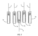
- FIG. 5 is a side elevation view of a coupling assembly according to another embodiment of the invention.
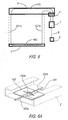
- FIG. 6 is a front elevation view of a window covering according to an embodiment of the invention.
- FIG. 6a is a perspective view of a cord-gripping member, showing a portion of the bottom rail in phantom;
- FIG. 7 is a side elevation view of a coupling assembly according to another embodiment of the invention.
- the coupling member for use in a coupling assembly or "equalizer” is shown.
- the coupling member includes a cordlock member 7a, with an internal cavity 8 and an orifice 9.
- the coupling member also includes a shear-gripping surface modifier 10, a lift cord 1 or a pull cord 6 and, optionally, a cord retainer 11.
- the surface modifier 10 which grips strongly in shear but easily separates in peel or tension perpendicular to the surface of cordlock member 7a, is applied to one or two opposite faces of cordlock member 7a.
- Surface modifiers for use on cordlock member 7a include, for example, Velcro TM and Duo-Lock TM (3M Corporation), both of which are of the multi-element interlocking type, are available in ribbons or pre-cut patches, and may include pressure-sensitive adhesive backings to attach to cordlock member 7a.
- surface modifier 10 may include a brittle glue with low peel strength (but high shear strength), an integral interlocking texturing of cordlock member 7a itself, a peelable tack surface (like the tack surface used in Post-It TM notes (also from 3M Corporation)), or combinations thereof.
- interlocking surfaces are preferred because of their reusability, which allows for repositioning and relative adjustment of the cords 1, 6 to equalize their loads.
- Duo-LockTM is preferred further because VelcroTM includes pairs of two distinct surface types; whereas Duo-Lock is hermaphroditic, allowing all surface modifiers 10 to be identical.
- a coupling assembly 7 attaches two lift cords 1 and a single pull cord 6.
- each of cords 1, 6 is passed into a cordlock member 7a through orifice 9, optionally through retainer 11, and then knotted or otherwise secure to cordlock member 7a.
- the positions of each outer cordlock member 7a may be different (vertically) to easily accommodate variations in the lengths of the cords 1.
- the coupling assembly is shown in FIG. 3 as "exploded", the surface modifiers 10 are actually engaged in use.
- cordlock member 7a on pullcord 6 carries surface modifiers 10 on each face, while outer cordlock members 7a on lift cords 1 do not require modifiers on their outer faces.
- FIGS. 4 and 5 other embodiments of the coupling assembly 7 of the present invention are shown.
- the coupling assembly 7 is substantially similar to the coupling assembly shown in FIG. 3 with at least one exception, namely, the middle cordlock member 7a is also attached to a lift cord 1.
- the coupling assembly is substantially similar to the coupling assembly shown in FIG. 3 with at least one exception, namely, two additional cordlock members 7a are added outward of the original cordlock members shown in FIG. 3. It will be appreciated that both odd and even numbered coupling assemblies of any cordlock member count may be handled with additional repetitions of the embodiments shown in FIGS. 4 and 5.
- the present invention provides a convenient, compact and adjustable way of joining multiple lift cords into a single pull cord and to receive tension therefrom via shearing forces on the joined surfaces, while providing very low separating force if those surfaces are peeled apart, as by a person's hand or neck accidentally entangled between any two cords. Further, no small parts become separated from the coupling member even in such an entanglement event, further avoiding the problem of lost or swallowed components.
- FIGS. 2-5 are not limited to the illustrations shown. Variations of the embodiments illustrated in the drawings include, for example: (a) differently-shaped cordlock members 7a, perhaps with side openings or other retaining features for the cords; (b) attachment of multiple cords to more than two faces of a central cordlock member or assembling multiple cordlock members in other than a linear-stacked array; (c) replacing the pull cord 6 with a rigid or resilient wand element; (d) providing a decorative, easily separated sheath over the multiple cordlock members in a visually-integrated manner; (e) attaching a pull cord to each cordlock member 7a; and (f) using no pull cord and letting the cluster of cordlock members serve as a tassel for the user's grip.
- the components of coupling assembly 7 shown in FIGS. 2-5 are conducive to being easily manufactured from commonly-used materials, such as plastics.
- the coupling assembly 7 is readily assembled and can be configured with multiples of one or more key components to accommodate different numbers of shade cords.
- the present invention also enables rapid and revisable equalization of exposed cord lengths, either during or after manufacture and installation, and eliminates one of the most difficult operations in the fabrication of corded shades (i.e., equalizing co-fixed cords).
- the coupling assembly 7 of the present invention provides reliable, repeatable, and adjustable equalization both during and after initial assembly.
- coupling assembly 7 reduces the cost of manufacture, eliminate perceived flaws of uneven hanging once installed, and allow simple owner adjustments to equalization throughout the life of the product to accommodate any wear or stretch in the components.
- coupling assembly 7 provides enhanced safety against the risk of entanglement injury by allowing very low force separation of cordlock members 7a when an object larger than the width of cordlock members 7a (such as an arm or child's neck) is placed between adjacent cords, forcing the mating surfaces apart.
- FIG. 6 another embodiment of the present invention is shown.
- the underlying concept of this embodiment is the unification of the multiple lift cords into a single loop of cord traversing the moving rail of the shade and the single point of operator contact (or attachment of such contact if a secondary pull-cord is used).
- the unified loop can be gripped locally to define the positional relationship between the operator contact point and the two parts of the loop (either side of the grip point). By varying the grip location on the loop and, accordingly, the relative lengths of the two loop parts, equalization of the shade is effected.
- a window covering is provided that includes a loop cord 101, including cord portions 101a and 101b, and a gripping member 102. While the window covering shown in FIG. 6 includes a single loop cord, it will be appreciated that multiple loop cords, nested across the width of shade (all "a" portions to one side and all “b" portions to the other) are also within the scope of the invention.
- the gripping member 102 may be a discrete device, like a clamp, or a passive device, such as a device that provides frictional resistance to cord passage at a close-fit orifice. In a particular configuration illustrated in FIG.
- the gripping member 102 is a small membrane (e.g., a square having about 3/4 inch sides) of resilient polyester sheeting material, about 5 to 10 thousandths of an inch thick, having a slit 102a of predetermined length (e.g., one-half inch long).
- the cord 101 is passed through slit 102a, preferably in a direction perpendicular to the direction of the slit to minimize a tendency of the cord to migrate and jam at an end of the slit.
- the membrane In the disclosed position within the bottom rail, the membrane is preferably oriented in a horizontal plane and secured by pressure-sensitive adhesion to the upwardly-facing inner surface of the bottom wall of bottom rail 2.
- the membrane could be secured to the underside of the stiffener that is typically secured to the lowermost portion of the shade fabric for retaining the fabric within the bottom rail.
- the window covering shown in FIG. 6 may also include a coupling assembly similar to the coupling assembly shown in FIGS. 2-5 and describe above.
- a coupling assembly for use with the window covering of FIG. 6, is shown in FIG. 7.
- the coupling assembly 7 includes one cordlock member 7a secured to each of the two cord ends of loop cord 101. Further, at least one of the cordlock members 7a is modified to directly receive and attach a pull cord 6 as shown in FIG. 7.
- the combination of a single loop cord 101, equalized at the bottom rail 2, with the coupling assembly 7 of the present invention i.e.
- FIGS. 6 and 7 are not limited to the illustrations shown. Some exemplary variants to the embodiments illustrated in the drawings would include, for example: (a) multiple loop cords (nested to allow rail tilting) for four, six or more cord runs in a shade; (b) a single, central cord, affixed to the bottom rail, with a loop cord providing two outer cord runs in a "three-cord” shade; (c) use of the loop-cord in-rail equalizer with separating cord coupling members other than those shown in FIGS.
- the invention shown in FIGS. 6 and 7 is conducive to being easily incorporated into conventional shades and fabrication methods, with any required parts or modifications manufactured from commonly-used materials, such as plastics. It is more readily assembled than conventionally-equalized shades either during or after manufacture and installation. It eliminates one of the most difficult operations in the fabrication of corded shades (equalizing co-fixed cords) and can be configured with multiples of the same key components to accommodate different numbers of shade cords.
- the invention shown in FIGS. 6 and 7 provides reliable, repeatable, and adjustable equalization both during and after initial assembly. This will reduce cost of manufacture, perceived flaws of uneven hanging once installed, and simple owner adjustments to equalization throughout the life of the product to accommodate any wear or stretch. Further, the window covering shown in FIG.
Landscapes
- Engineering & Computer Science (AREA)
- Structural Engineering (AREA)
- Architecture (AREA)
- Civil Engineering (AREA)
- Blinds (AREA)
- Curtains And Furnishings For Windows Or Doors (AREA)
Applications Claiming Priority (2)
| Application Number | Priority Date | Filing Date | Title |
|---|---|---|---|
| US53737004P | 2004-01-17 | 2004-01-17 | |
| US537370P | 2004-01-17 |
Publications (2)
| Publication Number | Publication Date |
|---|---|
| EP1555383A2 true EP1555383A2 (de) | 2005-07-20 |
| EP1555383A3 EP1555383A3 (de) | 2008-12-10 |
Family
ID=34619680
Family Applications (1)
| Application Number | Title | Priority Date | Filing Date |
|---|---|---|---|
| EP05250135A Withdrawn EP1555383A3 (de) | 2004-01-17 | 2005-01-13 | Fensterabdeckung und Trennkupplung |
Country Status (4)
| Country | Link |
|---|---|
| US (1) | US7311132B2 (de) |
| EP (1) | EP1555383A3 (de) |
| AU (1) | AU2005200139A1 (de) |
| CA (1) | CA2492432A1 (de) |
Cited By (1)
| Publication number | Priority date | Publication date | Assignee | Title |
|---|---|---|---|---|
| EP2019184A3 (de) * | 2007-07-25 | 2014-04-30 | Hunter Douglas Inc. | Zugseilsystem für einziehbare Abdeckung |
Families Citing this family (8)
| Publication number | Priority date | Publication date | Assignee | Title |
|---|---|---|---|---|
| US8776859B2 (en) * | 2009-10-28 | 2014-07-15 | James G. Frederick | Safety device for window covering operator |
| USD671352S1 (en) | 2010-12-02 | 2012-11-27 | Hunter Douglas Industries Bv | Cord connector housing |
| USD664832S1 (en) | 2010-12-02 | 2012-08-07 | Hunter Douglas Industries Bv | Cord receiver |
| USD671350S1 (en) | 2010-12-02 | 2012-11-27 | Hunter Douglas Industries Bv | Tassel for a cord |
| USD671351S1 (en) | 2010-12-02 | 2012-11-27 | Hunter Douglas Industries Bv | Tassel housing |
| US9500025B2 (en) | 2014-07-18 | 2016-11-22 | The Shade Store, Llc | Breakaway cord connector |
| US10392859B2 (en) | 2016-02-18 | 2019-08-27 | Hunter Douglas Inc. | Rail for an architectural covering |
| US11891855B2 (en) | 2020-01-28 | 2024-02-06 | Levolor, Inc. | Leveling assembly for adjusting the levelness of a bottom rail of a covering for an architectural structure |
Citations (1)
| Publication number | Priority date | Publication date | Assignee | Title |
|---|---|---|---|---|
| US6550522B1 (en) | 2002-03-28 | 2003-04-22 | Dennis R. Lennon | Level adjuster for window shades |
Family Cites Families (11)
| Publication number | Priority date | Publication date | Assignee | Title |
|---|---|---|---|---|
| US2733527A (en) * | 1956-02-07 | Strand-loop fastener | ||
| US2438101A (en) * | 1944-10-09 | 1948-03-16 | Richard H Wright | Cord equalizer for venetian blinds |
| US2809409A (en) * | 1952-02-21 | 1957-10-15 | Eastern Venetian Blind Company | Cord equalizer |
| US3280890A (en) * | 1964-12-24 | 1966-10-25 | Levolor Lorentzen Inc | Venetian-blind construction for taking up lift-cord slack |
| US4441540A (en) * | 1982-04-30 | 1984-04-10 | Ohline Corporation | Bottom rail structural configuration for a venetian blind |
| US4673018A (en) * | 1984-11-13 | 1987-06-16 | Verosol Usa Inc. | Sun blind |
| US4739816A (en) * | 1985-08-30 | 1988-04-26 | Levolor Lorentzen, Inc. | Venetian blind system for greenhouses |
| US4639977A (en) * | 1986-02-27 | 1987-02-03 | Howard William R | Combination rope guard and rope bundle keeper |
| US4909298A (en) * | 1988-09-26 | 1990-03-20 | Langhart Richard M | Window covering cord pull safety device |
| US5628091A (en) * | 1996-01-05 | 1997-05-13 | Mueller; Herbert | Balloon closure device |
| US5848488A (en) * | 1997-06-07 | 1998-12-15 | Interstate Graphics | Hanging sign |
-
2005
- 2005-01-11 US US11/033,251 patent/US7311132B2/en not_active Expired - Fee Related
- 2005-01-13 AU AU2005200139A patent/AU2005200139A1/en not_active Abandoned
- 2005-01-13 CA CA002492432A patent/CA2492432A1/en not_active Abandoned
- 2005-01-13 EP EP05250135A patent/EP1555383A3/de not_active Withdrawn
Patent Citations (1)
| Publication number | Priority date | Publication date | Assignee | Title |
|---|---|---|---|---|
| US6550522B1 (en) | 2002-03-28 | 2003-04-22 | Dennis R. Lennon | Level adjuster for window shades |
Cited By (1)
| Publication number | Priority date | Publication date | Assignee | Title |
|---|---|---|---|---|
| EP2019184A3 (de) * | 2007-07-25 | 2014-04-30 | Hunter Douglas Inc. | Zugseilsystem für einziehbare Abdeckung |
Also Published As
| Publication number | Publication date |
|---|---|
| US7311132B2 (en) | 2007-12-25 |
| AU2005200139A1 (en) | 2005-08-04 |
| EP1555383A3 (de) | 2008-12-10 |
| CA2492432A1 (en) | 2005-07-17 |
| US20050199353A1 (en) | 2005-09-15 |
Similar Documents
| Publication | Publication Date | Title |
|---|---|---|
| US7096917B2 (en) | One way brake for a cordless blind | |
| US20110186242A1 (en) | Safety Mechanism for a Window Covering | |
| US8122931B2 (en) | Window covering | |
| US7311132B2 (en) | Self-equalizing corded window covering and breakaway coupling member for same | |
| US4635698A (en) | Cord equalizer for locking together a plurality of cords of a blind assembly | |
| US5906233A (en) | Safety device and system for window covering pull cords | |
| US7331370B1 (en) | Progressive resistance lifting mechanism for a window covering | |
| US5743319A (en) | Window blind with safety pull cord | |
| CA2470918A1 (en) | Releasable cord connecter for window blind | |
| CA2682579C (en) | A window covering | |
| US6845803B1 (en) | Cord member safety connector for window blind | |
| AU2015280291B2 (en) | Devices and systems for accumulating lift cords used to lift architectural opening coverings | |
| US20100212120A1 (en) | Releasable clip for a shade | |
| CN102282389A (zh) | 拉手 | |
| US7198089B2 (en) | Pull cord operation mechanism for blinds | |
| US6910517B1 (en) | Equalizing connector for multi-cord architectural covering | |
| US5823242A (en) | Safety tassel for pull cords | |
| US20070000618A1 (en) | Roman blind assembly | |
| EP2221443B1 (de) | Fensterabdeckung | |
| EP0666404B1 (de) | Seilklemme für Rafflamellenstore | |
| US20050161171A1 (en) | Corded architectural covering including cord actuator and locking system | |
| US7219710B2 (en) | Lifting mechanism for window shades | |
| CN102536082A (zh) | 用于窗户覆盖物的安全机构 | |
| JP3026454B2 (ja) | ローマンシェード等の昇降コードストッパー | |
| JPH07217338A (ja) | ブラインド用ストッパ装置 |
Legal Events
| Date | Code | Title | Description |
|---|---|---|---|
| PUAI | Public reference made under article 153(3) epc to a published international application that has entered the european phase |
Free format text: ORIGINAL CODE: 0009012 |
|
| AK | Designated contracting states |
Kind code of ref document: A2 Designated state(s): AT BE BG CH CY CZ DE DK EE ES FI FR GB GR HU IE IS IT LI LT LU MC NL PL PT RO SE SI SK TR |
|
| AX | Request for extension of the european patent |
Extension state: AL BA HR LV MK YU |
|
| RAP1 | Party data changed (applicant data changed or rights of an application transferred) |
Owner name: COMFORTEX CORPORATION |
|
| PUAL | Search report despatched |
Free format text: ORIGINAL CODE: 0009013 |
|
| AK | Designated contracting states |
Kind code of ref document: A3 Designated state(s): AT BE BG CH CY CZ DE DK EE ES FI FR GB GR HU IE IS IT LI LT LU MC NL PL PT RO SE SI SK TR |
|
| AX | Request for extension of the european patent |
Extension state: AL BA HR LV MK YU |
|
| RIC1 | Information provided on ipc code assigned before grant |
Ipc: E06B 9/388 20060101ALI20081103BHEP Ipc: E06B 9/32 20060101ALI20081103BHEP Ipc: E06B 9/326 20060101AFI20050511BHEP |
|
| 17P | Request for examination filed |
Effective date: 20090514 |
|
| RAP1 | Party data changed (applicant data changed or rights of an application transferred) |
Owner name: COMFORTEX CORPORATION |
|
| RAP1 | Party data changed (applicant data changed or rights of an application transferred) |
Owner name: COMFORTEX CORPORATION |
|
| AKX | Designation fees paid |
Designated state(s): CH DE FR GB IT LI NL SE |
|
| RAP1 | Party data changed (applicant data changed or rights of an application transferred) |
Owner name: COMFORTEX CORPORATION |
|
| RAP1 | Party data changed (applicant data changed or rights of an application transferred) |
Owner name: COMFORTEX CORPORATION |
|
| 17Q | First examination report despatched |
Effective date: 20110415 |
|
| STAA | Information on the status of an ep patent application or granted ep patent |
Free format text: STATUS: THE APPLICATION IS DEEMED TO BE WITHDRAWN |
|
| 18D | Application deemed to be withdrawn |
Effective date: 20110802 |