EP1555148A1 - Klimatisierungsvorrichtung, insbesondere für ein Kraftfahrzeug - Google Patents
Klimatisierungsvorrichtung, insbesondere für ein Kraftfahrzeug Download PDFInfo
- Publication number
- EP1555148A1 EP1555148A1 EP04290089A EP04290089A EP1555148A1 EP 1555148 A1 EP1555148 A1 EP 1555148A1 EP 04290089 A EP04290089 A EP 04290089A EP 04290089 A EP04290089 A EP 04290089A EP 1555148 A1 EP1555148 A1 EP 1555148A1
- Authority
- EP
- European Patent Office
- Prior art keywords
- air
- flap
- conditioning device
- outflow
- outflow opening
- Prior art date
- Legal status (The legal status is an assumption and is not a legal conclusion. Google has not performed a legal analysis and makes no representation as to the accuracy of the status listed.)
- Granted
Links
Images


Classifications
-
- B—PERFORMING OPERATIONS; TRANSPORTING
- B60—VEHICLES IN GENERAL
- B60H—ARRANGEMENTS OF HEATING, COOLING, VENTILATING OR OTHER AIR-TREATING DEVICES SPECIALLY ADAPTED FOR PASSENGER OR GOODS SPACES OF VEHICLES
- B60H1/00—Heating, cooling or ventilating [HVAC] devices
- B60H1/00642—Control systems or circuits; Control members or indication devices for heating, cooling or ventilating devices
- B60H1/00664—Construction or arrangement of damper doors
- B60H1/00671—Damper doors moved by rotation; Grilles
-
- B—PERFORMING OPERATIONS; TRANSPORTING
- B60—VEHICLES IN GENERAL
- B60H—ARRANGEMENTS OF HEATING, COOLING, VENTILATING OR OTHER AIR-TREATING DEVICES SPECIALLY ADAPTED FOR PASSENGER OR GOODS SPACES OF VEHICLES
- B60H1/00—Heating, cooling or ventilating [HVAC] devices
- B60H1/00007—Combined heating, ventilating, or cooling devices
- B60H1/00021—Air flow details of HVAC devices
- B60H1/00035—Air flow details of HVAC devices for sending an air stream of uniform temperature into the passenger compartment
- B60H1/0005—Air flow details of HVAC devices for sending an air stream of uniform temperature into the passenger compartment the air being firstly cooled and subsequently heated or vice versa
-
- B—PERFORMING OPERATIONS; TRANSPORTING
- B60—VEHICLES IN GENERAL
- B60H—ARRANGEMENTS OF HEATING, COOLING, VENTILATING OR OTHER AIR-TREATING DEVICES SPECIALLY ADAPTED FOR PASSENGER OR GOODS SPACES OF VEHICLES
- B60H1/00—Heating, cooling or ventilating [HVAC] devices
- B60H1/00007—Combined heating, ventilating, or cooling devices
- B60H1/00021—Air flow details of HVAC devices
- B60H2001/00078—Assembling, manufacturing or layout details
- B60H2001/00092—Assembling, manufacturing or layout details of air deflecting or air directing means inside the device
-
- B—PERFORMING OPERATIONS; TRANSPORTING
- B60—VEHICLES IN GENERAL
- B60H—ARRANGEMENTS OF HEATING, COOLING, VENTILATING OR OTHER AIR-TREATING DEVICES SPECIALLY ADAPTED FOR PASSENGER OR GOODS SPACES OF VEHICLES
- B60H1/00—Heating, cooling or ventilating [HVAC] devices
- B60H1/00007—Combined heating, ventilating, or cooling devices
- B60H1/00021—Air flow details of HVAC devices
- B60H2001/00078—Assembling, manufacturing or layout details
- B60H2001/00107—Assembling, manufacturing or layout details characterised by the relative position of the heat exchangers, e.g. arrangements leading to a curved airflow
-
- B—PERFORMING OPERATIONS; TRANSPORTING
- B60—VEHICLES IN GENERAL
- B60H—ARRANGEMENTS OF HEATING, COOLING, VENTILATING OR OTHER AIR-TREATING DEVICES SPECIALLY ADAPTED FOR PASSENGER OR GOODS SPACES OF VEHICLES
- B60H1/00—Heating, cooling or ventilating [HVAC] devices
- B60H1/00007—Combined heating, ventilating, or cooling devices
- B60H1/00021—Air flow details of HVAC devices
- B60H2001/00114—Heating or cooling details
- B60H2001/00128—Electric heaters
Definitions
- the present invention relates to an air conditioning device for Air conditioning of a room, in particular a motor vehicle interior with the features of the preamble of the claim 1.
- An air conditioning system of a motor vehicle usually has several in the vehicle interior opening outflow openings, the optionally supplied with cooled or heated air can.
- at least two outflow openings each in the footwell, in the area of a center console and above a dashboard provided, at least one on each Driver and a passenger side.
- To distribute the air-conditioned Air on the various outflow openings is this in known Air conditioning systems each assigned at least one adjusting device, by means of which a passage opening is variably opened or can be closed.
- adjusting devices are usually designed as swiveling flaps, which is a channel cross-section of an air duct each Partially or completely release or lock according to angular position can. So that each of these hinged flaps individually controlled can be, is in each case an actuator, for example, an electric Actuator o. The like. Necessary.
- EP 1 266 777 A1 is a vehicle air conditioning and a Air distribution module known in which a housing a passage for a steering column of the vehicle.
- the arrangement of the rest Components such as blower, cooling and heating device as well as the Air distribution channels is tuned so that the steering column without Functional impairment due to the housing and to the components can be passed over.
- the present invention is based on the object, an air conditioner for indoor temperature control or air conditioning to provide that is characterized by a simple and compact Structure and characterized by a simple controllability.
- an air distribution between at least two in the room or in the motor vehicle interior opening outflow openings is variably adjustable by means of at least one distribution flap.
- a variable Air distribution between two adjacent outflow openings achieved become.
- a first outflow opening can, for example, in a footwell the motor vehicle interior open, while a second Outflow opening, for example, in an upper area of the motor vehicle interior can lead.
- the invention sees at least one distribution flap for variably closing or releasing two or three adjacent ones Outflow before. If in the present context of several flaps and outflow the speech is, then it is basically the equipment of a page one Interior meant.
- Outflow openings at least in pairs for a left and right side exists so the following remarks each relate to a group of outflow openings on the left or the right side or within the center console are arranged.
- An embodiment of the invention provides that for variable air distribution between three outflow openings opening into the room two distribution flaps are provided.
- the air distribution between two adjacent outflow openings respectively by means a distribution flap arranged between them variably adjustable.
- a first distributor flap may be between a first outflow opening and a second outflow opening, while a second distribution flap between the second outflow opening and a third outflow opening can.
- Both distributor flaps have a first and a first second stop position, in each case one of the outflow openings is closed.
- the air flow can be variable between the be divided two adjacent outflow openings.
- An alternative variant provides that for variable air distribution between three outflow openings opening into the interior only a distribution flap is provided, in particular as so-called.
- Drum flap can be formed. In two stop positions as well as in a middle position, only one outflow opening in each case pressurized with air, while the other two closed are.
- An intermediate position acts on two or three of the outflow openings with conditioned air.
- the invention provides Arrangement a smaller number of flaps than Outlet openings are present. This can be compared to the known air conditioning devices at least one distribution flap be saved, which also simplifies the Kinematics for controlling the distributor flap results. A flap offers in each case the possibility to lock two air outlets.
- the Air conditioning device according to the invention can from this Reason to be very simple, inexpensive and compact.
- An air distributor of an air conditioning device comprises a housing with a blower disposed therein, a cooling device, a heating device as well as for each side of the vehicle interior at least three outlets for air supply. These three outflow openings are each in the manner described above by means of a or two distribution flaps can be variably closed or released.
- the air distributor according to the invention is simple and needs compared to known devices less movable control elements.
- FIG. 1 illustrates in a schematic representation of the structure and the basic function of an air conditioning device according to the invention 10.
- a housing 11 includes an air duct 12th and has a fan 13 for generating an air flow the air duct 12.
- a cooling device 14 is arranged upstream of a filter 16 can be.
- the cooling device 14 is usually a so-called evaporator or a heat exchanger device and serves for Cooling of the air flow conveyed by the fan 13 15.
- Downstream the cooling device 14 is a heating device 18, which is arranged in a lower branch channel 20.
- Parallel to this branch passage 20 extends an additional bypass channel 21, which are closed by means of a mixing flap 22 can.
- This mixing flap 22 serves to regulate the air temperature, because with closed flap 22, the entire subsidized Air flows through the branch channel 20 and the heater 18, while at open blend flap 22, the air due to lower resistance past the heater 18 through the Bypass passage 21 flows.
- the air duct 12 opens after the Branching back into a single channel and leading in the shown Embodiment for three outflow openings 24, 26, 28, respectively in a motor vehicle interior (not shown) open.
- the first outflow opening 24 is directed downwards and serves usually for air conditioning or heating a footwell of the vehicle interior.
- the second outflow opening 26 may be For example, located in a dashboard and is used for air conditioning or heating a central region of the vehicle interior, while the upwardly directed third outflow opening 28 in the first Line for heating or ventilating a windshield and / or side windows of the vehicle, for example, to this to keep fog free.
- the third outflow opening 28 also has a defroster function.
- the outflow openings 24, 26 and 28 shown in Figure 1 in pairs available for each side of the vehicle interior.
- the heater 18 may be a series of electrically heated Have wires that flows through the air to be heated become.
- a PTC element 30 be provided, in the illustrated embodiment, the heater is downstream and that for faster warming up can serve a desired temperature.
- a first distribution flap 32 is arranged, having the two stop positions.
- a second Distributor flap 34 is arranged, which also has two stop positions having.
- Figure 2 illustrates a Defrostergna, in which the first Distributor flap 32 is located in a first stop position, so that the first outflow opening 24 is completely closed.
- the second Distributor flap 32 is also in a first stop position, in which the second outflow opening 26 is completely closed is. It is in this case of all three outflow openings 24, 26th and 28 only the third outflow opening 28 is opened, which in the direction directed to the windshield.
- the air conditioning device 10 is the blend door 22 preferably closed, so that the bypass channel 21 is closed is and the entire conditioned air through the branch channel 20 with the heater 18 arranged therein flows.
- the heater 18 ensures the desired warming of the air-conditioned Air to fog the disc as fast as possible respectively to get rid of ice.
- the heated air is as an arrow with the reference numeral 36 illustrates.
- FIG. 3 shows a ventilation position, in which the first distributor flap 32 is again in the first stop position, so that the first outflow opening 24 is closed in the footwell direction.
- the second distributor flap 34 is here in a second Stop position in which the third outflow opening 28 is closed and the second outflow opening 26 is released.
- In this ventilation position can the mixing flap 22 is closed or be partially open, depending on the temperature of the Vehicle occupant is desired.
- Figure 4 illustrates a further possibility of setting the air conditioning device 10, in which the first distribution flap 32 in a second stop position is brought, at the second outflow opening 26 and third outflow opening 28 are closed. The first outflow opening 24 is released here.
- the blend door 22 may optionally be in an open position for air conditioning or in a closed position for heating be brought to the footwell.
- the position of the second distribution flap 34 is irrelevant here, since the entire air 36 for first outflow opening 24 is passed.
- Figure 5 illustrates a possible intermediate position, in which the mixing flap 22 is partially open, so the conditioned air 36 partially through the bypass channel 21 and partly through the Branch channel 20 with the heater 18 flows. Also the first Distributor flap 32 is in an intermediate position, so that the conditioned and partially heated air 36 both through the first Outflow opening 24 and through the second outflow opening 26 can flow. The second distribution flap 34 is located in second stop position, so that the third outflow opening 28th is closed.
- FIG. 6 shows an alternative setting in which the first distributor flap 32 is in an intermediate position and at the second distribution flap 34 is brought into the first stop position, such that the first outflow opening 24 and the third outflow opening 28 are released.
- This setting can be used to warm up the Footwell and for defrosting or to prevent fogging Vehicle window be suitable.
- the two distribution flaps 32 and 34 as well brought the mixing flap 22 in any intermediate positions be, so that according to need an air conditioning respectively Heating one, two or all three interior zones possible is.
- Figures 1 to 6 illustrate the extremely compact design of According to the invention air conditioning device 10. They illustrate In addition, the air distribution on three outflow openings of an interior zone by means of only two distribution flaps in the desired Way is controllable.
- the second distributor flap 34 takes over here at the same time the variable control of the air distribution to two adjacent Outlet openings 26 and 28.
- a third distribution flap is not necessary.
- the control of the two distribution flaps 32nd and 34 and the mixing flap 22 may suitably For example, by means of electric servomotors o.
- Figures 7 to 12 show an alternative embodiment of the air conditioning device 10 in a schematic representation.
- the upper Area with the air outlet openings 24 to 28 is opposite the first variant again significantly more compact.
- the two distribution flaps 32 and 34 are arranged so close to each other, that results in an overlap of their pivoting ranges.
- the two distribution flaps 32 and 34 must for this reason in their pivotal movements so coupled with each other that they do not collide with each other.
- the second and third outflow openings 26 and 28 border in one Edge to each other. In this corner area is a pivot axis 38 of the second distribution flap 34, depending on their position the second outflow opening 26 or the third outflow opening 28 can close.
- FIG. 8 shows a defrost position, in which the mixing flap 22 and the first distribution flap 32 are closed.
- the second distribution flap 34 is brought into the first stop position, in which the second outflow opening 26 is closed and the third outflow opening 28 is opened.
- the first outflow opening 24 is closed by the first distribution flap 32.
- the heated Air 36 flows exclusively through the third outflow opening 28 towards the windscreen and / or the side windows of the vehicle.
- Figure 9 shows a normal ventilation position, in which compared to Defroster ein of Figure 8, the second distribution valve 34 in the second stop position is brought.
- the second outflow opening 26 is hereby opened while the third outflow opening 28 is closed is.
- the mixing flap 22 can optionally be opened or be closed or in a middle position, depending on desired temperature control of the air 36.
- Figure 10 shows a whoraumbeliciungswolf in which the first Distributor flap 32 is brought into the second stop position. in this connection is the second outflow opening 26 by means of the first distributor flap 32 closed, while the third outflow opening 28 of the second distribution flap 34 is closed.
- the blend flap 22 may be either open or closed, or itself in a middle position, depending on the desired temperature the air 36.
- FIG. 11 shows a combined position for foot and interior ventilation, in which the first distribution flap 32 in an intermediate position is located so that the air 36 both from the first and also can flow out of the second outflow opening 24 and 26.
- the third outflow opening 28 is in turn from the second distribution flap 34 closed.
- FIG. 12 shows a combined position for foot space and window ventilation; in which the first distribution flap 32 in an intermediate position is located at the first outflow opening 24 is opened is.
- the second distribution flap 34 is in the first stop position, in which the second outflow opening 26 is closed and the third discharge port 28 is opened.
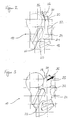
- FIG. 13 shows a third variant in a schematic sectional illustration an air conditioning device 10 according to the invention instead two air distribution flaps is only a single distributor flap present, in the present context as a third distribution flap 38 is designated.
- the third distributor flap 38 the form of a so-called drum door, as they the air-conditioned Air depending on the pivot position in one of the outflow openings 24, 26th and 28 and closes the other outflow openings.
- the third distributor flap 38 is for this purpose about a pivot axis 40th pivotable, which are arranged transversely to the flow direction of the air is.
- FIG. 15 illustrates a first stop position of the third distributor flap 38, in which the third outflow opening 28 is released.
- the first outflow opening 24 and the second outflow opening 26 are closed here.
- FIG. 16 illustrates a second stop position the third distributor flap 38, in which the second outflow opening 26 is released.
- the first outflow opening 24 and the third outflow opening 28 are closed in this case.
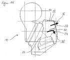
- FIG. 17 illustrates a middle position, in which only the first outflow 24 is opened, while the other two outflow openings closed are.
- FIGs 18 and 19 illustrate each intermediate positions of third distributor flap 38, in which two of the three outflow openings 24, 26 and 28 are partially released, while the third Outlet opening is closed in each case.
- the middle position shown in FIG. 17 can be used in particular for footwell air conditioning be provided because the first outflow openings 24 open laterally on the housing 11.
- the third distributor flap 38 is shaped accordingly, so that the air is led to the side.
- the position of the mixing flap is irrelevant, since at all shown operating conditions both cold and warm air can be promoted.
- All shown variants of the air conditioning device 10 have a very compact case design and allow the Air distribution on three outflow openings by means of two air distribution flaps or even just a flap in the desired manner Taxes. Compared with known air conditioners can in this way at least one flap can be saved, resulting in a simplified Construction, to a simplified control and to a Reduction of manufacturing costs leads.
Landscapes
- Physics & Mathematics (AREA)
- Thermal Sciences (AREA)
- Engineering & Computer Science (AREA)
- Mechanical Engineering (AREA)
- Air-Conditioning For Vehicles (AREA)
Abstract
Description
- Figur 1
- eine schematische Perspektivdarstellung einer ersten Variante einer erfindungsgemäßen Klimatisierungsvorrichtung,
- Figuren 2 bis 6
- verschiedene Betriebszustände der Klimatisierungsvorrichtung gemäß Figur 1,
- Figur 7
- eine schematische Perspektivdarstellung einer zweiten Variante der erfindungsgemäßen Klimatisierungsvorrichtung,
- Figuren 8 bis 12
- verschiedene Betriebszustände der Klimatisierungsvorrichtung gemäß Figur 7,
- Figur 13
- eine schematische Perspektivdarstellung einer dritten Variante der erfindungsgemäßen Klimatisierungsvorrichtung,
- Figur 14
- eine Luftverteilerklappe der Klimatisierungsvorrichtung entsprechend Figur 13 und die
- Figuren 15 bis 19
- verschiedene Betriebszustände der Klimatisierungsvorrichtung gemäß Figur 13.
Claims (19)
- Klimatisierungsvorrichtung zur Klimatisierung eines Raumes, insbesondere eines Kraftfahrzeuginnenraumes, mit einem Luftführungskanal (12) und einer darin angeordneten Kühleinrichtung (14) sowie einer stromabwärts der Kühleinrichtung (14) in einem Zweigkanal (20) angeordneten Heizeinrichtung (18), und mit einem parallel zum Zweigkanal (20) verlaufenden Bypasskanal (21), wobei die Luftverteilung zwischen dem Zweigkanal (20) und dem Bypasskanal (21) mittels wenigstens einer Mischungsklappe (22) variabel einstellbar ist, dadurch gekennzeichnet, dass eine Luftverteilung zwischen wenigstens zwei in den Raum bzw. in den Kraftfahrzeuginnenraum mündenden Ausströmöffnungen (24, 26, 28) mittels wenigstens einer Verteilerklappe (32, 34, 38) variabel einstellbar ist.
- Klimatisierungsvorrichtung nach Anspruch 1, dadurch gekennzeichnet, dass zur variablen Luftverteilung zwischen drei in den Raum mündenden Ausströmöffnungen (24, 26, 28) eine Verteilerklappe (38) vorgesehen ist.
- Klimatisierungsvorrichtung nach Anspruch 1, dadurch gekennzeichnet, dass zur variablen Luftverteilung zwischen drei in den Raum mündenden Ausströmöffnungen (24, 26, 28) zwei Verteiierkiappen (32, 34) vorgesehen sind.
- Klimatisierungsvorrichtung nach einem der voranstehenden Ansprüche, dadurch gekennzeichnet, dass die Luftverteilung zwischen zwei benachbarten Ausströmöffnungen (24 und 26 bzw. 26 und 28) jeweils mittels einer zwischen diesen angeordneten Verteilerklappe (32 bzw. 34; 38) variabel einstellbar ist.
- Klimatisierungsvorrichtung nach einem der voranstehenden Ansprüche, dadurch gekennzeichnet, dass die Luftverteilung zwischen drei benachbarten Ausströmöffnungen (24, 26, 28) mittels einer zwischen diesen angeordneten Verteilerklappe (38) variabel einstellbar ist.
- Klimatisierungsvorrichtung nach einem der voranstehenden Ansprüche, dadurch gekennzeichnet, dass eine erste Verteilerklappe (32) zwischen einer ersten Ausströmöffnung (24) und einer zweiten Ausströmöffnung (26) angeordnet ist.
- Klimatisierungsvorrichtung nach einem der voranstehenden Ansprüche, dadurch gekennzeichnet, dass eine zweite Verteilerklappe (34) zwischen der zweiten Ausströmöffnung (26) und einer dritten Ausströmöffnung (28) angeordnet ist.
- Klimatisierungsvorrichtung nach einem der voranstehenden Ansprüche, dadurch gekennzeichnet, dass in einer ersten Anschlagstellung der ersten Verteilerklappe (32) die erste Ausströmöffnung (24) verschlossen ist.
- Klimatisierungsvorrichtung nach einem der voranstehenden Ansprüche, dadurch gekennzeichnet, dass in einer zweiten Anschlagstellung der ersten Verteilerklappe (32) die zweiten und dritten Ausströmöffnungen (26 und 28) verschlossen sind.
- Klimatisierungsvorrichtung nach einem der voranstehenden Ansprüche, dadurch gekennzeichnet, dass in einer ersten Anschlagstellung der zweiten Verteilerklappe (34) die zweite Ausströmöffnung (26) verschlossen und die dritte Ausströmöffnung (28) freigegeben ist.
- Klimatisierungsvorrichtung nach einem der voranstehenden Ansprüche, dadurch gekennzeichnet, dass in einer zweiten Anschlagstellung der zweiten Verteilerklappe (34) die zweite Ausströmöffnung (26) freigegeben und die dritte Ausströmöffnung (28) verschlossen ist.
- Klimatisierungsvorrichtung nach einem der voranstehenden Ansprüche, dadurch gekennzeichnet, dass die erste und die zweite Verteilerklappe (32, 34) jeweils in eine Zwischenstellung bringbar ist, bei der wenigstens zwei Ausströmöffnungen (24, 26, 28) teilweise freigegeben sind.
- Klimatisierungsvorrichtung nach einem der Ansprüche 1 bis 5, dadurch gekennzeichnet, dass eine dritte Verteilerklappe (38) stromaufwärts der Ausströmöffnungen (24, 26, 28) angeordnet ist.
- Klimatisierungsvorrichtung nach Anspruch 13, dadurch gekennzeichnet, dass in einer ersten Anschlagstellung der dritten Verteilerklappe (38) die dritte Ausströmöffnung (28) geöffnet ist und die weiteren Ausströmöffnungen (24, 26) verschlossen sind.
- Klimatisierungsvorrichtung nach Anspruch 13 oder 14, dadurch gekennzeichnet, dass in einer zweiten Anschlagstellung der dritten Verteilerklappe (38) die zweite Ausströmöffnung (26) geöffnet ist und die weiteren Ausströmöffnungen (24, 28) verschlossen sind.
- Klimatisierungsvorrichtung nach einem der Ansprüche 13 bis 15, dadurch gekennzeichnet, dass in einer Mittelstellung der dritten Verteilerklappe (38) die erste Ausströmöffnung (24) geöffnet ist und die weiteren Ausströmöffnungen (26, 28) verschlossen sind.
- Klimatisierungsvorrichtung nach einem der Ansprüche 13 bis 16, dadurch gekennzeichnet, dass in einer Zwischenstellung der dritten Verteilerklappe (38) die erste, zweite und/oder dritte Ausströmöffnung (24, 26, 28) teilweise geöffnet bzw. verschlossen sind.
- Klimatisierungsvorrichtung nach einem der voranstehenden Ansprüche, dadurch gekennzeichnet, dass für jede Seite des Fahrzeuginnenraums jeweils wenigstens eine erste, eine zweite sowie eine dritte Ausströmöffnung (24, 26, 28) vorgesehen ist, die mittels wenigstens einer Verteilerklappe (32, 34, 38) variabel öffenbar bzw. verschließbar sind.
- Luftverteiler einer Klimatisierungsvorrichtung (10) gemäß einem der Ansprüche 1 bis 18, der ein Gehäuse (11) mit darin angeordnetem Gebläse (13), eine Kühleinrichtung (14), eine Heizeinrichtung (18) sowie für jede Seite des Fahrzeuginnenraumes wenigstens drei Ausströmöffnungen (24, 26, 28) aufweist, die mittels wenigstens einer Verteilerklappe (32, 34, 38) variabel öffenbar bzw. verschließbar sind.
Priority Applications (2)
| Application Number | Priority Date | Filing Date | Title |
|---|---|---|---|
| EP20040290089 EP1555148B1 (de) | 2004-01-13 | 2004-01-13 | Klimatisierungsvorrichtung, insbesondere für ein Kraftfahrzeug |
| DE200450006404 DE502004006404D1 (de) | 2004-01-13 | 2004-01-13 | Klimatisierungsvorrichtung, insbesondere für ein Kraftfahrzeug |
Applications Claiming Priority (1)
| Application Number | Priority Date | Filing Date | Title |
|---|---|---|---|
| EP20040290089 EP1555148B1 (de) | 2004-01-13 | 2004-01-13 | Klimatisierungsvorrichtung, insbesondere für ein Kraftfahrzeug |
Publications (2)
| Publication Number | Publication Date |
|---|---|
| EP1555148A1 true EP1555148A1 (de) | 2005-07-20 |
| EP1555148B1 EP1555148B1 (de) | 2008-03-05 |
Family
ID=34610230
Family Applications (1)
| Application Number | Title | Priority Date | Filing Date |
|---|---|---|---|
| EP20040290089 Expired - Fee Related EP1555148B1 (de) | 2004-01-13 | 2004-01-13 | Klimatisierungsvorrichtung, insbesondere für ein Kraftfahrzeug |
Country Status (2)
| Country | Link |
|---|---|
| EP (1) | EP1555148B1 (de) |
| DE (1) | DE502004006404D1 (de) |
Citations (5)
| Publication number | Priority date | Publication date | Assignee | Title |
|---|---|---|---|---|
| US5775407A (en) * | 1995-12-26 | 1998-07-07 | Denso Corporation | Dual zone air conditioning apparatus with sealing portions on partition wall |
| DE19707405A1 (de) * | 1997-02-25 | 1998-08-27 | Valeo Klimasysteme Gmbh | Luftverteilervorrichtung |
| DE19842875A1 (de) * | 1997-09-25 | 1999-04-01 | Denso Corp | Klimaanlage für ein Fahrzeug |
| EP1266777A1 (de) | 2000-03-13 | 2002-12-18 | Zexel Valeo Climate Control Corporation | Fahrzeugklimanlage und armaturenbrettmodule |
| EP1319540A2 (de) * | 2001-12-11 | 2003-06-18 | Denso Corporation | Fahrzeugklimaanlage mit Rotationstür |
-
2004
- 2004-01-13 EP EP20040290089 patent/EP1555148B1/de not_active Expired - Fee Related
- 2004-01-13 DE DE200450006404 patent/DE502004006404D1/de not_active Expired - Lifetime
Patent Citations (5)
| Publication number | Priority date | Publication date | Assignee | Title |
|---|---|---|---|---|
| US5775407A (en) * | 1995-12-26 | 1998-07-07 | Denso Corporation | Dual zone air conditioning apparatus with sealing portions on partition wall |
| DE19707405A1 (de) * | 1997-02-25 | 1998-08-27 | Valeo Klimasysteme Gmbh | Luftverteilervorrichtung |
| DE19842875A1 (de) * | 1997-09-25 | 1999-04-01 | Denso Corp | Klimaanlage für ein Fahrzeug |
| EP1266777A1 (de) | 2000-03-13 | 2002-12-18 | Zexel Valeo Climate Control Corporation | Fahrzeugklimanlage und armaturenbrettmodule |
| EP1319540A2 (de) * | 2001-12-11 | 2003-06-18 | Denso Corporation | Fahrzeugklimaanlage mit Rotationstür |
Also Published As
| Publication number | Publication date |
|---|---|
| DE502004006404D1 (de) | 2008-04-17 |
| EP1555148B1 (de) | 2008-03-05 |
Similar Documents
| Publication | Publication Date | Title |
|---|---|---|
| EP1607254B1 (de) | Vorrichtung zur Luftzuführung in einen Innenraum eines Fahrzeuges | |
| DE10012975C1 (de) | Heizungs- oder Klimaanlage | |
| WO2006027219A2 (de) | Modulare kraftfahrzeug-klimaanlage | |
| DE102015110481A1 (de) | Vorrichtung zum Beheizen, Belüften und/oder Klimatisieren eines Fahrzeuginnenraums | |
| DE19804287C1 (de) | Klimaanlage für Fahrzeuge | |
| EP2030816B1 (de) | Klimaanlage für ein Kraftfahrzeug mit einer Fondraumklappe zum Mischen und Verteilen der Luft | |
| EP1306241B1 (de) | Fahrzeugheiz- und Klimaanlage mit kombinierter Luftmisch- und -verteilklappe | |
| EP1761405B1 (de) | Klimaanlage, insbesondere kraftfahrzeug-klimaanlage | |
| DE3911616C3 (de) | Heiz- oder Klimaanlage für den Fahrgastraum von Kraftfahrzeugen | |
| DE4243165A1 (de) | Klimagerät für ein Kraftfahrzeug | |
| EP1555148B1 (de) | Klimatisierungsvorrichtung, insbesondere für ein Kraftfahrzeug | |
| DE10045438A1 (de) | Klimaanlage für ein Kraftfahrzeug | |
| EP1555147B1 (de) | Klimatisierungsvorrichtung für ein Kraftfahrzeug | |
| WO2005084973A1 (de) | Klimatisierungsvorrichtung, insbesondere für ein kraftfahrzeug | |
| EP1738941A1 (de) | Kraftfahrzeug-Klimaanlage | |
| EP1531067B1 (de) | Klimatisierungsvorrichtung, insbesondere für ein Kraftfahrzeug | |
| EP2277728A1 (de) | Klimaanlage | |
| EP1479545B1 (de) | Klimaanlage, insbesondere für Fahrzeuge sowie Verfahren zur Klimatisierung | |
| EP1319538B1 (de) | Heiz- oder Klimaanlage für ein Kraftfahrzeug | |
| EP1281542B1 (de) | Klimaanlage | |
| DE102021209994A1 (de) | Klimaanlage eines Kraftfahrzeugs | |
| EP1348581B1 (de) | Mehrkanalige Heizungs- und/oder Klimaanlage für ein Kraftfahrzeug | |
| EP1319539B1 (de) | Heiz- oder Klimaanlage für ein Kraftfahrzeug | |
| WO2014012897A2 (de) | Klimaanlage | |
| EP1344663B1 (de) | Mehrkanalige Heizungs- und/oder Klimaanlage für ein Kraftfahrzeug |
Legal Events
| Date | Code | Title | Description |
|---|---|---|---|
| PUAI | Public reference made under article 153(3) epc to a published international application that has entered the european phase |
Free format text: ORIGINAL CODE: 0009012 |
|
| AK | Designated contracting states |
Kind code of ref document: A1 Designated state(s): AT BE BG CH CY CZ DE DK EE ES FI FR GB GR HU IE IT LI LU MC NL PT RO SE SI SK TR |
|
| AX | Request for extension of the european patent |
Extension state: AL LT LV MK |
|
| RAP1 | Party data changed (applicant data changed or rights of an application transferred) |
Owner name: BEHR FRANCE ROUFFACH SAS |
|
| 17P | Request for examination filed |
Effective date: 20060120 |
|
| AKX | Designation fees paid |
Designated state(s): CZ DE FR |
|
| 17Q | First examination report despatched |
Effective date: 20060321 |
|
| GRAP | Despatch of communication of intention to grant a patent |
Free format text: ORIGINAL CODE: EPIDOSNIGR1 |
|
| GRAS | Grant fee paid |
Free format text: ORIGINAL CODE: EPIDOSNIGR3 |
|
| GRAA | (expected) grant |
Free format text: ORIGINAL CODE: 0009210 |
|
| AK | Designated contracting states |
Kind code of ref document: B1 Designated state(s): CZ DE FR |
|
| REF | Corresponds to: |
Ref document number: 502004006404 Country of ref document: DE Date of ref document: 20080417 Kind code of ref document: P |
|
| ET | Fr: translation filed | ||
| PLBE | No opposition filed within time limit |
Free format text: ORIGINAL CODE: 0009261 |
|
| STAA | Information on the status of an ep patent application or granted ep patent |
Free format text: STATUS: NO OPPOSITION FILED WITHIN TIME LIMIT |
|
| 26N | No opposition filed |
Effective date: 20081208 |
|
| PG25 | Lapsed in a contracting state [announced via postgrant information from national office to epo] |
Ref country code: CZ Free format text: LAPSE BECAUSE OF NON-PAYMENT OF DUE FEES Effective date: 20090113 |
|
| PGFP | Annual fee paid to national office [announced via postgrant information from national office to epo] |
Ref country code: FR Payment date: 20110209 Year of fee payment: 8 |
|
| REG | Reference to a national code |
Ref country code: FR Ref legal event code: ST Effective date: 20120928 |
|
| PG25 | Lapsed in a contracting state [announced via postgrant information from national office to epo] |
Ref country code: FR Free format text: LAPSE BECAUSE OF NON-PAYMENT OF DUE FEES Effective date: 20120131 |
|
| REG | Reference to a national code |
Ref country code: DE Ref legal event code: R082 Ref document number: 502004006404 Country of ref document: DE Representative=s name: GRAUEL, ANDREAS, DIPL.-PHYS. DR. RER. NAT., DE Ref country code: DE Ref legal event code: R081 Ref document number: 502004006404 Country of ref document: DE Owner name: MAHLE INTERNATIONAL GMBH, DE Free format text: FORMER OWNER: BEHR FRANCE ROUFFACH S.A.S., ROUFFACH, FR |
|
| PGFP | Annual fee paid to national office [announced via postgrant information from national office to epo] |
Ref country code: DE Payment date: 20190131 Year of fee payment: 16 |
|
| REG | Reference to a national code |
Ref country code: DE Ref legal event code: R119 Ref document number: 502004006404 Country of ref document: DE |
|
| PG25 | Lapsed in a contracting state [announced via postgrant information from national office to epo] |
Ref country code: DE Free format text: LAPSE BECAUSE OF NON-PAYMENT OF DUE FEES Effective date: 20200801 |