EP1553639A1 - Solar tile assembly - Google Patents
Solar tile assembly Download PDFInfo
- Publication number
- EP1553639A1 EP1553639A1 EP05075682A EP05075682A EP1553639A1 EP 1553639 A1 EP1553639 A1 EP 1553639A1 EP 05075682 A EP05075682 A EP 05075682A EP 05075682 A EP05075682 A EP 05075682A EP 1553639 A1 EP1553639 A1 EP 1553639A1
- Authority
- EP
- European Patent Office
- Prior art keywords
- support structure
- outer panel
- inner support
- electrical
- solar tile
- Prior art date
- Legal status (The legal status is an assumption and is not a legal conclusion. Google has not performed a legal analysis and makes no representation as to the accuracy of the status listed.)
- Granted
Links
Images




Classifications
-
- H—ELECTRICITY
- H02—GENERATION; CONVERSION OR DISTRIBUTION OF ELECTRIC POWER
- H02S—GENERATION OF ELECTRIC POWER BY CONVERSION OF INFRARED RADIATION, VISIBLE LIGHT OR ULTRAVIOLET LIGHT, e.g. USING PHOTOVOLTAIC [PV] MODULES
- H02S20/00—Supporting structures for PV modules
- H02S20/20—Supporting structures directly fixed to an immovable object
- H02S20/22—Supporting structures directly fixed to an immovable object specially adapted for buildings
- H02S20/23—Supporting structures directly fixed to an immovable object specially adapted for buildings specially adapted for roof structures
- H02S20/25—Roof tile elements
-
- H—ELECTRICITY
- H10—SEMICONDUCTOR DEVICES; ELECTRIC SOLID-STATE DEVICES NOT OTHERWISE PROVIDED FOR
- H10F—INORGANIC SEMICONDUCTOR DEVICES SENSITIVE TO INFRARED RADIATION, LIGHT, ELECTROMAGNETIC RADIATION OF SHORTER WAVELENGTH OR CORPUSCULAR RADIATION
- H10F19/00—Integrated devices, or assemblies of multiple devices, comprising at least one photovoltaic cell covered by group H10F10/00, e.g. photovoltaic modules
- H10F19/80—Encapsulations or containers for integrated devices, or assemblies of multiple devices, having photovoltaic cells
-
- Y—GENERAL TAGGING OF NEW TECHNOLOGICAL DEVELOPMENTS; GENERAL TAGGING OF CROSS-SECTIONAL TECHNOLOGIES SPANNING OVER SEVERAL SECTIONS OF THE IPC; TECHNICAL SUBJECTS COVERED BY FORMER USPC CROSS-REFERENCE ART COLLECTIONS [XRACs] AND DIGESTS
- Y02—TECHNOLOGIES OR APPLICATIONS FOR MITIGATION OR ADAPTATION AGAINST CLIMATE CHANGE
- Y02B—CLIMATE CHANGE MITIGATION TECHNOLOGIES RELATED TO BUILDINGS, e.g. HOUSING, HOUSE APPLIANCES OR RELATED END-USER APPLICATIONS
- Y02B10/00—Integration of renewable energy sources in buildings
- Y02B10/10—Photovoltaic [PV]
-
- Y—GENERAL TAGGING OF NEW TECHNOLOGICAL DEVELOPMENTS; GENERAL TAGGING OF CROSS-SECTIONAL TECHNOLOGIES SPANNING OVER SEVERAL SECTIONS OF THE IPC; TECHNICAL SUBJECTS COVERED BY FORMER USPC CROSS-REFERENCE ART COLLECTIONS [XRACs] AND DIGESTS
- Y02—TECHNOLOGIES OR APPLICATIONS FOR MITIGATION OR ADAPTATION AGAINST CLIMATE CHANGE
- Y02E—REDUCTION OF GREENHOUSE GAS [GHG] EMISSIONS, RELATED TO ENERGY GENERATION, TRANSMISSION OR DISTRIBUTION
- Y02E10/00—Energy generation through renewable energy sources
- Y02E10/50—Photovoltaic [PV] energy
Definitions
- the present invention relates to a solar tile assembly and is concerned particularly with a two part solar roofing tile and a method for providing electrical connection between the respective parts of the two part solar roofing tile.
- photovoltaic modules that may be placed onto the exterior of a building or replace the existing roof tiles. Examples of such photovoltaic modules are described in US 5590495, US 5112408 and EP 0710806.
- the photovoltaic modules systems normally comprise a plurality of solar panels that are electrically connected to form a circuit. The solar panels may require routine maintenance that necessitates the removal of one or more of the solar panels.
- a solar tile assembly comprising a removable outer panel that comprises photovoltaic means and a first electrical connector, the first electrical connector being provided underneath the outer panel, and an inner support structure that comprises a second electrical connector, the arrangement being such that in use an electrical connection between the first electrical connector and the second electrical connector is achieved by bringing together the outer panel and the inner support structure.
- the electrical connection between the first electrical connector and the second electrical connector is preferably broken by the removal of the outer panel from the inner support structure.
- the outer panel is slidably attached to the inner support structure by attachment means comprising a channel section formed to receive an attachment element.
- the outer panel comprises the attachment element and the inner support structure is formed with the channel for receiving and retaining the attachment element of the outer panel.
- the outer panel conveniently comprises a pair of attachment elements and the inner support structure is formed with a pair of channels for receiving and retaining the attachment elements of the outer panel.
- the electrical connection between the first electrical connector and the second electrical connector is preferably broken by sliding the outer panel in a direction that is substantially parallel to plane of outermost surface of the outer panel.
- the outer panel is removed from the inner support structure by first sliding the outer panel in a direction that is substantially parallel to plane of outermost surface of the outer panel and then lifting the outer panel in a direction perpendicular to the direction of the slide direction.
- the inner support structure can be attached to the outer surface of a structure such as a building. If necessary a damaged outer panel can be easily removed from the solar tile assembly whilst still leaving the inner support structure fixed to the building. A new outer panel can then replace the damaged outer panel. Also, the outer panel and the inner support structure can be easily inspected by removing the outer panel.
- the inner support structure preferably comprises an electrical junction box comprising the second electrical connector.
- the electrical junction box of the inner support structure preferably comprises an electrical input terminal and an electrical output terminal, the arrangement being such that the electrical input terminal and the electrical output terminal provide electrical communication between corresponding solar tile assemblies.
- the photovoltaic means of the respective solar assemblies generate electrical energy and there may be an electrical network provided between the plurality of solar title assemblies.
- the outer panel comprises an electrical junction box formed with the first electrical connector, the arrangement being such that in the assembled state of the solar tile assembly the first connector and the second connector provide electrical communication between the two electrical junction boxes.
- the solar tile assemblies may be conveniently fixed to roof battens of a conventional roof structure and may replace the roofing tiles.
- the support structure comprises means for providing electrical connections between adjacent solar tile assemblies.
- the means for providing electrical connections between adjacent solar tile assemblies preferably comprises an electrical connector on opposite sides of the support structure.
- a removable solar tile comprising photovoltaic means and an electrical connector, the first electrical connector being provided underneath the tile, the arrangement being such that in use an electrical connection between the electrical connector of the removable solar tile and a second electrical connector of an inner support structure is achieved by the bringing together of the outer panel and the inner support structure.
- an inner support structure for a removable tile comprising photovoltaic means, the inner support structure comprising an electrical connector, the arrangement being such that in use an electrical connection between the electrical connector of the inner support structure and an electrical connector of the removable tile is achieved by the bringing together of the removable tile and the inner support structure, and the electrical connector of the inner support structure being adapted to connect with the electrical connector of the removable tile which is provided underneath the removable tile.
- the electrical connection between the respective parts of the solar tile assembly is broken by sliding the outer panel in the opposite direction.
- the invention may include any combination of the features or limitations referred to herein.
- a solar tile assembly 1A comprises a removable rectangular outer panel 1 that comprises ten photovoltaic cells 3 disposed on the outermost surface thereof, and a substantially rectangular inner support structure 2.
- the photovoltaic cells 3 cover the lower portion of the outer panel 1. Any suitable photovoltaic means may be used for the solar tile assembly.
- the outer panel 1 is secured to the inner support structure 2 using two fasteners 5a, 5b disposed at the front end of the solar tile assembly 1A.
- the fasteners 5a, 5b may typically be quarter or half turn captive fasteners. These types of fasteners have the added advantage of being retained by the outer panel 1 during assembly/disassembly processes.
- the inner support structure 2 comprises a framework at one of which there is formed a lower stepped interlockable section 4. In use the interlockable section 4 is disposed under a portion of an adjacent tile assembly, as is well known in the art of roof tile design.
- the inner support structure 2 is formed with three sets of holes 6. These holes 6 allow fixing nails or screws to be used to attach the inner structure 2 to roof tiling battens located underneath the inner structure 2. For certain roof designs no fixing nails or screws will be needed to hold the tile assembly 1A onto the roof.
- an electrical junction box 7 Disposed within the frame of the support structure 2 there is an electrical junction box 7.
- the inner support structure 2 comprises two parallel end members 7a, 7b (shown in Figures 3 to 5).
- each of the respective end members 7a, 7b there are respective slide channels 8a, 8b. At one end of the slide channel 8a there is formed a cutaway access port 9a. At the corresponding end of the slide channel 8b (not shown) there is formed a cutaway access port 9b.
- the outer panel 1 comprises a pair of attachment elements 17a, 17b fixed to the inner surface of the outer panel 1 (see Figure 5).
- the attachment elements 17a, 17b are a triangular wedge shape.
- a heel portion 17c extends from each of the respective vertical faces of the wedge shapes.
- the attachment elements 17a, 17b are shaped to be received by the access ports 9a, 9b.
- each channel 10 there is provided an access port 10a, 10b.
- Each port 10a, 10b has a greater width than the width of the remaining portions of the respective channels 10.
- the ports 10a, 10b provide access to the channels 10 for two variable gauge clips 11a, 11b.
- channels 10 may be used in place of the slide channels 8a, 8b.
- Channels 10 can operate to perform the function of channels 8a, 8b by comprising two sets of slide fixtures, one set being attached to the outer panel 1.
- the clips 11a, 11b may slide along the channels 10 and are used to fix the outer panel 1 to an outer panel of an adjacent solar panel assembly located below.
- the electrical junction box 7 of the inner support structure 2 comprises a pair of electrical connectors 13, an electrical output lead 14 and an electrical input connector 15.
- the outer panel 1 comprises an electrical junction box 19 that comprises a pair of electrical connectors 19a. In the assembled closed condition of the solar tile assembly 1A (as shown in Figure 1) the electrical connectors 13 are in electrical contact with the electrical connectors 19a.
- the outer panel 1 is first slid in a direction Z and this causes a break in the electrical connection between the connectors 13 and the connectors 19a.
- the outer panel 1 is slid in the direction Z until the attachment elements 17a, 17b abut the respective lowermost ends of the channels 10.
- the outer panel 1 will stay in this position without sliding completely off the support structure 2 (as shown in Figure 2).
- the outer panel 1 is moved back a small distance in the opposite direction to direction Z until the attachment elements 17a, 17b align with the respective access ports 9a, 9b.
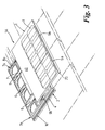
- the outer panel 1 can then be lifted away from the inner support structure 2 (as shown in Figure 3).
- the inwardly-extending lip 20 on the front underside of the outer panel 1 fits under a recess 12 that is formed in the lowermost edge of the inner support structure 2 so providing secure anchorage against high wind.
- the outer panel 1 is constructed typically of two planar sheets of material (see Figure 5).
- the uppermost sheet is a transparent material 22a that permits sunlight to reach the photovoltaic elements.
- the uppermost sheet 22a is larger on three sides than the lowermost sheet 22b and all the fixing arrangements are mounted underneath and inside this area. Hence, no joints exist which could cause water ingress when exposed to the weather.
- the materials that may be used for the construction of the parts of the solar tile assembly 1A include metallic or non-metallic including plastics, glass, metal and ceramics/clay/cement.
- the underside of the inner support structure 2 has location points to allow it to be easily positioned on the roof of a building and also to retain it in position whilst fixing down.
- the variable gauge clips 11a, 11b may be used to fix the outer panel 1 to a tile assembly located in a row below, should added retention be required for example in high wind speed areas.
- the electrical connection between the outer panel 1 and the inner support structure 2 of the solar tile assembly 1A is made as the outer panel 1 is assembled onto the inner support structure 2.
- the electrical connection between the outer panel 1 and the inner support structure 2 of the solar tile assembly 1A is broken as the outer panel 1 is disassembled from the inner support structure 2.
- the electrical connection between the connectors 13 and the connectors 19a is retained by use of fasteners 5a, 5b located on the front edge of the outer panel 1.
- fasteners 5a, 5b located on the front edge of the outer panel 1.
- the fasteners 5a, 5b are undone and outer panel 1 is released the electrical connection will be broken as the outer panel 1 slides in direction Z.
- the junction box 7 will be exposed, therefore allowing access to all necessary electrical components.
- Flying leads 14 may be used to connect adjacent solar tile assemblies together to complete a circuit.
- Fixed connections 16 may also be used on the sides of the inner support structure 2 such that as a solar tile assembly is positioned adjacent to another solar tile assembly, an electrical connection can be made because the two parts of the connector 16 (male and female) are integral with the parts of adjacent tiles assemblies.
- a cable would normally have to run from the end of the last row along the roof to the start of the second row. This uses a considerable amount of cable and therefore incurs electrical losses.
- An alternative arrangement may be made where the wiring of the connections is reversed in alternate rows. The end tile assembly can then be directly connected with a short wire to the next row above or below.
- the inner support structure 2 of the tile assembly may be colour coded so that during assembly it is easy to lay alternative rows with the correct wiring arrangement.
- the dimensions of the solar panel assembly 1A can be made to correspond with the dimensions of conventional roof tiles. Hence, the solar tile assembly can be easily fitted onto an existing roof.
- the roof may be partially covered by an array of solar tile assemblies and partially covered by conventional roof tiles. Due to the construction and configuration of the solar tile assembly 1A, the outer panel 1 of an assembly 1A can be removed from the array of assemblies without disturbing the other assemblies.
- the solar tile assembly can be attached to any suitable structure outside or inside a building.
Landscapes
- Engineering & Computer Science (AREA)
- Architecture (AREA)
- Civil Engineering (AREA)
- Structural Engineering (AREA)
- Roof Covering Using Slabs Or Stiff Sheets (AREA)
- Photovoltaic Devices (AREA)
- Road Paving Structures (AREA)
- Inorganic Insulating Materials (AREA)
- Finishing Walls (AREA)
Abstract
Description
- The present invention relates to a solar tile assembly and is concerned particularly with a two part solar roofing tile and a method for providing electrical connection between the respective parts of the two part solar roofing tile.
- It is known to use solar panels comprising photovoltaic modules that may be placed onto the exterior of a building or replace the existing roof tiles. Examples of such photovoltaic modules are described in US 5590495, US 5112408 and EP 0710806. The photovoltaic modules systems normally comprise a plurality of solar panels that are electrically connected to form a circuit. The solar panels may require routine maintenance that necessitates the removal of one or more of the solar panels.
- According to a first aspect of the present invention there is provided a solar tile assembly comprising a removable outer panel that comprises photovoltaic means and a first electrical connector, the first electrical connector being provided underneath the outer panel, and an inner support structure that comprises a second electrical connector, the arrangement being such that in use an electrical connection between the first electrical connector and the second electrical connector is achieved by bringing together the outer panel and the inner support structure.
- The electrical connection between the first electrical connector and the second electrical connector is preferably broken by the removal of the outer panel from the inner support structure.
- Preferably, the outer panel is slidably attached to the inner support structure by attachment means comprising a channel section formed to receive an attachment element.
- Preferably, the outer panel comprises the attachment element and the inner support structure is formed with the channel for receiving and retaining the attachment element of the outer panel.
- The outer panel conveniently comprises a pair of attachment elements and the inner support structure is formed with a pair of channels for receiving and retaining the attachment elements of the outer panel.
- The electrical connection between the first electrical connector and the second electrical connector is preferably broken by sliding the outer panel in a direction that is substantially parallel to plane of outermost surface of the outer panel.
- Preferably the outer panel is removed from the inner support structure by first sliding the outer panel in a direction that is substantially parallel to plane of outermost surface of the outer panel and then lifting the outer panel in a direction perpendicular to the direction of the slide direction.
- In use the inner support structure can be attached to the outer surface of a structure such as a building. If necessary a damaged outer panel can be easily removed from the solar tile assembly whilst still leaving the inner support structure fixed to the building. A new outer panel can then replace the damaged outer panel. Also, the outer panel and the inner support structure can be easily inspected by removing the outer panel.
- The inner support structure preferably comprises an electrical junction box comprising the second electrical connector.
- The electrical junction box of the inner support structure preferably comprises an electrical input terminal and an electrical output terminal, the arrangement being such that the electrical input terminal and the electrical output terminal provide electrical communication between corresponding solar tile assemblies. In use the photovoltaic means of the respective solar assemblies generate electrical energy and there may be an electrical network provided between the plurality of solar title assemblies.
- It is preferable that the outer panel comprises an electrical junction box formed with the first electrical connector, the arrangement being such that in the assembled state of the solar tile assembly the first connector and the second connector provide electrical communication between the two electrical junction boxes.
- The solar tile assemblies may be conveniently fixed to roof battens of a conventional roof structure and may replace the roofing tiles.
- According to an embodiment of the first invention the support structure comprises means for providing electrical connections between adjacent solar tile assemblies.
- The means for providing electrical connections between adjacent solar tile assemblies preferably comprises an electrical connector on opposite sides of the support structure.
- According to a second aspect of the present invention there is provided a removable solar tile comprising photovoltaic means and an electrical connector, the first electrical connector being provided underneath the tile, the arrangement being such that in use an electrical connection between the electrical connector of the removable solar tile and a second electrical connector of an inner support structure is achieved by the bringing together of the outer panel and the inner support structure.
- According to a third aspect of the present invention there is provided an inner support structure for a removable tile comprising photovoltaic means, the inner support structure comprising an electrical connector, the arrangement being such that in use an electrical connection between the electrical connector of the inner support structure and an electrical connector of the removable tile is achieved by the bringing together of the removable tile and the inner support structure, and the electrical connector of the inner support structure being adapted to connect with the electrical connector of the removable tile which is provided underneath the removable tile.
- Preferably the electrical connection between the respective parts of the solar tile assembly is broken by sliding the outer panel in the opposite direction.
- The invention may include any combination of the features or limitations referred to herein.
- The invention can be put into practice is various ways, but an embodiment will now be described by way of example only with reference to the accompanying drawings in which:
- Figure 1 is an isometric view of a solar tile assembly in a closed assembled condition;
- Figure 2 is an isometric view of the solar tile assembly shown in Figure 1 and shows the assembly in a partially open condition;
- Figure 3 is an isometric view of the solar tile assembly shown in Figure 1 and shows the outer panel separated from the inner support frame;
- Figure 4 is an isometric view of the solar tile assembly shown in Figure 1 and shows the outer panel removed from the inner support frame; and
- Figure 5 is an isometric view of the solar tile assembly shown in Figure 1 and shows more detail of a variable gauge clip, more detail of the outer panel structure and three partial cut-away sections of the outer panel.
-
- With reference to the Figures 1 to 5, a
solar tile assembly 1A comprises a removable rectangular outer panel 1 that comprises tenphotovoltaic cells 3 disposed on the outermost surface thereof, and a substantially rectangularinner support structure 2. Thephotovoltaic cells 3 cover the lower portion of the outer panel 1. Any suitable photovoltaic means may be used for the solar tile assembly. - The outer panel 1 is secured to the
inner support structure 2 using twofasteners solar tile assembly 1A. Thefasteners - The
inner support structure 2 comprises a framework at one of which there is formed a lower steppedinterlockable section 4. In use theinterlockable section 4 is disposed under a portion of an adjacent tile assembly, as is well known in the art of roof tile design. Theinner support structure 2 is formed with three sets ofholes 6. Theseholes 6 allow fixing nails or screws to be used to attach theinner structure 2 to roof tiling battens located underneath theinner structure 2. For certain roof designs no fixing nails or screws will be needed to hold thetile assembly 1A onto the roof. Disposed within the frame of thesupport structure 2 there is anelectrical junction box 7. Theinner support structure 2 comprises twoparallel end members respective end members respective slide channels slide channel 8a there is formed acutaway access port 9a. At the corresponding end of theslide channel 8b (not shown) there is formed acutaway access port 9b. - The outer panel 1 comprises a pair of
attachment elements attachment elements attachment elements access ports - Also formed in the
inner support structure 2 there are two substantially parallel channels 10 (shown in Figures 4 and 5). At one end of eachchannel 10 there is provided anaccess port port respective channels 10. Theports channels 10 for twovariable gauge clips - It will be appreciated by the skilled person in the art that the
channels 10 may be used in place of theslide channels Channels 10 can operate to perform the function ofchannels - Should added retention for the solar tile assembly be required, for example in high winds, the
clips channels 10 and are used to fix the outer panel 1 to an outer panel of an adjacent solar panel assembly located below. - The
electrical junction box 7 of theinner support structure 2 comprises a pair ofelectrical connectors 13, anelectrical output lead 14 and anelectrical input connector 15. The outer panel 1 comprises anelectrical junction box 19 that comprises a pair ofelectrical connectors 19a. In the assembled closed condition of thesolar tile assembly 1A (as shown in Figure 1) theelectrical connectors 13 are in electrical contact with theelectrical connectors 19a. - To disassemble the
solar tile assembly 1A the outer panel 1 is first slid in a direction Z and this causes a break in the electrical connection between theconnectors 13 and theconnectors 19a. The outer panel 1 is slid in the direction Z until theattachment elements channels 10. The outer panel 1 will stay in this position without sliding completely off the support structure 2 (as shown in Figure 2). In order to separate the outer panel 1 from theinner support structure 2 the outer panel 1 is moved back a small distance in the opposite direction to direction Z until theattachment elements respective access ports - When the
solar tile assembly 1A is reassembled and the outer panel 1 is slid back up into position, the inwardly-extendinglip 20 on the front underside of the outer panel 1 fits under arecess 12 that is formed in the lowermost edge of theinner support structure 2 so providing secure anchorage against high wind. - The outer panel 1 is constructed typically of two planar sheets of material (see Figure 5). The uppermost sheet is a transparent material 22a that permits sunlight to reach the photovoltaic elements. In the embodiment shown, the uppermost sheet 22a is larger on three sides than the
lowermost sheet 22b and all the fixing arrangements are mounted underneath and inside this area. Hence, no joints exist which could cause water ingress when exposed to the weather. The materials that may be used for the construction of the parts of thesolar tile assembly 1A include metallic or non-metallic including plastics, glass, metal and ceramics/clay/cement. - The underside of the
inner support structure 2 has location points to allow it to be easily positioned on the roof of a building and also to retain it in position whilst fixing down. Thevariable gauge clips - The electrical connection between the outer panel 1 and the
inner support structure 2 of thesolar tile assembly 1A is made as the outer panel 1 is assembled onto theinner support structure 2. The electrical connection between the outer panel 1 and theinner support structure 2 of thesolar tile assembly 1A is broken as the outer panel 1 is disassembled from theinner support structure 2. - It will be noted by those skilled in the art that electrical connection between the outer panel 1 and the
inner support structure 2 can be broken without the complete separation of the parts because the outer panel 1 has a sliding arrangement with theinner support structure 2. - When the
solar tile assembly 1A is assembled, the electrical connection between theconnectors 13 and theconnectors 19a is retained by use offasteners fasteners channels 10 thejunction box 7 will be exposed, therefore allowing access to all necessary electrical components. - Flying leads 14 may be used to connect adjacent solar tile assemblies together to complete a circuit.
Fixed connections 16 may also be used on the sides of theinner support structure 2 such that as a solar tile assembly is positioned adjacent to another solar tile assembly, an electrical connection can be made because the two parts of the connector 16 (male and female) are integral with the parts of adjacent tiles assemblies. - As a row of tile assemblies is completed in the horizontal plane and the next row started, a cable would normally have to run from the end of the last row along the roof to the start of the second row. This uses a considerable amount of cable and therefore incurs electrical losses. An alternative arrangement may be made where the wiring of the connections is reversed in alternate rows. The end tile assembly can then be directly connected with a short wire to the next row above or below. In order to distinguish between the tile assemblies with the two types of wiring, the
inner support structure 2 of the tile assembly may be colour coded so that during assembly it is easy to lay alternative rows with the correct wiring arrangement. - The dimensions of the
solar panel assembly 1A can be made to correspond with the dimensions of conventional roof tiles. Hence, the solar tile assembly can be easily fitted onto an existing roof. The roof may be partially covered by an array of solar tile assemblies and partially covered by conventional roof tiles. Due to the construction and configuration of thesolar tile assembly 1A, the outer panel 1 of anassembly 1A can be removed from the array of assemblies without disturbing the other assemblies. - When there is an array of assemblies, the
upper portion 40 of the outer panel 1 that is not formed withphotovoltaic cells 3 because this area is normally covered by a lower portion of an upper adjacent solar tile assembly. - It will be appreciated that the solar tile assembly can be attached to any suitable structure outside or inside a building.
Claims (19)
- A solar tile assembly comprising a removable outer panel (1) that comprises photovoltaic means (3) and a first electrical connector (19a), the first electrical connector being provided underneath the outer panel, and an inner support structure (2) that comprises a second electrical connector (13), the arrangement being such that in use an electrical connection between the first electrical connector (19a) and the second electrical connector (13) is achieved by bringing together the outer panel (1) and the inner support structure (2).
- A solar tile assembly as claimed in claim 1, wherein the electrical connection between the first electrical connector and the second electrical connector is broken by the removal of the outer panel from the inner support structure.
- A solar tile assembly as claimed in claim 1 in which the removable outer panel (1) is adapted to be slidable on the inner support structure (2).
- A solar tile assembly as claimed in claim 1 or claim 2, wherein the outer panel is slidably attached to the inner support structure by attachment means comprising a channel section (8a, 8b) formed to receive an attachment element (17a, 17b).
- A solar tile assembly as claimed in claim 4, wherein the outer panel (2) comprises the attachment element (17a, 17b) and the inner support structure is formed with the channel (8a, 8b) for receiving and retaining the attachment element of the outer panel.
- A solar tile assembly as claimed in claim 4, wherein the outer panel comprises a pair of attachment elements (17a, 17b) and the inner support structure is formed with a pair of channels (8a, 8b) for receiving and retaining the attachment elements of the outer panel.
- A solar tile assembly as claimed in claim 1, wherein the electrical connection between the first electrical connector and the second electrical connector is broken by sliding the outer panel in a direction that is substantially parallel to plane of outermost surface of the outer panel.
- A solar tile assembly as claimed in any one of claims 1 to 7, wherein the outer panel is removed from the inner support structure by first sliding the outer panel in a direction that is substantially parallel to the plane of the outermost surface of the outer panel and then lifting the outer panel in a direction perpendicular to the direction of the slide direction.
- A solar tile assembly as claimed in any one of the preceding claims, wherein, in use, the inner support structure can be attached to the outer surface of a structure such as a building or attached to an independent support structure inside or outside a building.
- A solar tile assembly as claimed in any one of the preceding claims, wherein the inner support structure comprises an electrical junction box (7) that comprises the second electrical connector (13).
- A solar tile assembly as claimed in claim 10, wherein the electrical junction box of the inner support structure comprises an electrical input terminal (15) and an electrical output terminal (14), the arrangement being such that the electrical input terminal and the electrical output terminal provide electrical communication between corresponding solar tile assemblies.
- A solar tile assembly as claimed in claim 10 or claim 11, wherein the outer panel comprises an electrical junction box (19) formed with the first electrical connector, the assembly being such that in the assembled state of the solar tile assembly the first connector and the second connector provide electrical communication between the two electrical junction boxes.
- A solar tile assembly as claimed in claim 12 in which the outer removable panel (1) comprises a pair of electrical connectors (19a).
- A solar tile assembly as claimed in claim 13 in which the pair of electrical connectors (19a) extend away from the junction box (19).
- A solar tile assembly as claimed in any one of the preceding claims, wherein the support structure comprises means (16) for providing electrical connections between adjacent solar tile assemblies.
- A solar tile assembly as claimed in claim 15, wherein the means for providing electrical connections between adjacent solar tile assemblies comprises an electrical connector (16) on opposite sides of the support structure.
- A solar tile assembly as claimed in claim 1 in which the first electrical connector (19a) is located within the area bounded by the outer panel (1) when viewed in plan.
- A removable solar tile comprising photovoltaic means (3) and first electrical connector (19a), the first electrical connector being provided underneath the tile, the tile being such that in use an electrical connection between the electrical connector of the removable solar tile and a second electrical connector (13) of an inner support structure (12) is achieved by bringing together the outer panel and the inner support structure.
- An inner support structure for a removable tile that comprises photovoltaic means, the inner support structure comprising an electrical connector (13), the arrangement being such that in use an electrical connection between the electrical connector (13) of the inner support structure and an electrical connector (19a) of the removable tile (1) is achieved by bringing together the removable tile and the inner support structure, and the electrical connector of the inner support structure being adapted to connect with the electrical connector of the removable tile which is provided underneath the removable tile.
Applications Claiming Priority (3)
| Application Number | Priority Date | Filing Date | Title |
|---|---|---|---|
| GBGB9913705.1A GB9913705D0 (en) | 1999-06-14 | 1999-06-14 | Solar roofing tile |
| GB9913705 | 1999-06-14 | ||
| EP00940495A EP1190456B1 (en) | 1999-06-14 | 2000-06-14 | Solar tile assembly |
Related Parent Applications (1)
| Application Number | Title | Priority Date | Filing Date |
|---|---|---|---|
| EP00940495A Division EP1190456B1 (en) | 1999-06-14 | 2000-06-14 | Solar tile assembly |
Publications (2)
| Publication Number | Publication Date |
|---|---|
| EP1553639A1 true EP1553639A1 (en) | 2005-07-13 |
| EP1553639B1 EP1553639B1 (en) | 2008-05-07 |
Family
ID=10855237
Family Applications (2)
| Application Number | Title | Priority Date | Filing Date |
|---|---|---|---|
| EP05075682A Expired - Lifetime EP1553639B1 (en) | 1999-06-14 | 2000-06-14 | Solar tile assembly |
| EP00940495A Expired - Lifetime EP1190456B1 (en) | 1999-06-14 | 2000-06-14 | Solar tile assembly |
Family Applications After (1)
| Application Number | Title | Priority Date | Filing Date |
|---|---|---|---|
| EP00940495A Expired - Lifetime EP1190456B1 (en) | 1999-06-14 | 2000-06-14 | Solar tile assembly |
Country Status (10)
| Country | Link |
|---|---|
| US (2) | US6856496B1 (en) |
| EP (2) | EP1553639B1 (en) |
| JP (1) | JP2003506884A (en) |
| AT (2) | ATE394795T1 (en) |
| AU (1) | AU5542300A (en) |
| DE (2) | DE60034039T2 (en) |
| ES (2) | ES2283304T3 (en) |
| GB (1) | GB9913705D0 (en) |
| WO (1) | WO2000077860A2 (en) |
| ZA (1) | ZA200109802B (en) |
Cited By (1)
| Publication number | Priority date | Publication date | Assignee | Title |
|---|---|---|---|---|
| EP1920431A4 (en) * | 2005-08-03 | 2011-05-18 | Mark Banister | Electric tile modules |
Families Citing this family (75)
| Publication number | Priority date | Publication date | Assignee | Title |
|---|---|---|---|---|
| US6210117B1 (en) * | 1999-09-03 | 2001-04-03 | King Of Fans, Inc. | Device for connecting a fan blade to a rotor of a ceiling fan motor |
| GB9913705D0 (en) * | 1999-06-14 | 1999-08-11 | Univ Southampton | Solar roofing tile |
| JPWO2003029577A1 (en) * | 2001-09-28 | 2005-01-20 | 株式会社カネカ | Solar cell module, solar cell module laying method, and solar cell module blow-up prevention device |
| US20100314509A1 (en) | 2003-04-02 | 2010-12-16 | Conger Steven J | Solar array support methods and systems |
| US8875450B2 (en) | 2003-04-02 | 2014-11-04 | P4P Holdings, LLC | Solar array system for covering a body of water |
| US8381464B2 (en) * | 2003-04-02 | 2013-02-26 | P4P Holdings Llc | Solar array support methods and systems |
| US7285719B2 (en) * | 2003-04-02 | 2007-10-23 | Solar Suspension Systems, Llc | Solar array support methods and systems |
| US8278547B2 (en) * | 2003-04-02 | 2012-10-02 | P4P Holdings Llc | Solar array support methods and systems |
| US8429861B2 (en) * | 2003-04-02 | 2013-04-30 | P4P Holdings Llc | Solar array support methods and systems |
| US20080283112A1 (en) * | 2003-04-02 | 2008-11-20 | Conger Steven J | Solar array support methods and systems |
| US9564851B2 (en) | 2003-04-02 | 2017-02-07 | P4P Holdings, LLC | Solar array support methods and systems |
| US8212140B2 (en) * | 2003-04-02 | 2012-07-03 | P4P, Llc | Solar array support methods and systems |
| AU2003902270A0 (en) | 2003-05-09 | 2003-05-29 | Origin Energy Solar Pty Ltd | Separating and assembling semiconductor strips |
| USD649112S1 (en) | 2003-06-25 | 2011-11-22 | P4P Holdings, LLC | Solar array |
| USD605585S1 (en) | 2003-06-25 | 2009-12-08 | Solar Suspension Systems, Llc | Solar array |
| WO2005045942A1 (en) * | 2003-11-06 | 2005-05-19 | Firac International Co., Ltd. | Solar tile and its laying method |
| GB0502120D0 (en) * | 2005-02-02 | 2005-03-09 | Powertile Ltd | Solar tile assemblies |
| DE102005057468A1 (en) * | 2005-11-30 | 2007-05-31 | Solarwatt Solar-Systeme Ag | Plate-shaped frameless photovoltaic solar module has solar cells embedded between cover and rear materials and a rear strengthening structure |
| US8196360B2 (en) * | 2006-01-12 | 2012-06-12 | Msr Innovations Inc. | Photovoltaic solar roof tile assembly system |
| GB2435483B (en) * | 2006-02-28 | 2011-11-30 | Solar Century Holdings Ltd | Solar roof tile |
| US20100064605A1 (en) * | 2006-11-02 | 2010-03-18 | Roberto Corvaglia | Modular photovoltaic element for building roofs |
| FR2921397A1 (en) * | 2007-09-25 | 2009-03-27 | Mathieu Pierre Georges Rivot | Photovoltaic panels connecting and fixing device for e.g. building, has support provided with rubber pads and circular lower hooks, and independent circular upper hook inserted in rail and blocked by detent device |
| SG152074A1 (en) * | 2007-10-09 | 2009-05-29 | Dragon Energy Pte Ltd | Roof based energy conversion system |
| SG152072A1 (en) * | 2007-10-09 | 2009-05-29 | Dragon Energy Pte Ltd | Photovoltaic tile assembly |
| US8832938B2 (en) * | 2008-03-27 | 2014-09-16 | Panelclaw, Inc. | Ground mounted solar module integration system |
| US8748733B2 (en) * | 2008-03-27 | 2014-06-10 | Panelclaw, Inc. | Solar module integration system |
| US20090255530A1 (en) * | 2008-04-14 | 2009-10-15 | Abt, Inc. | Apparatus for mounting a solar panel and method and apparatus for forming the mounting apparatus |
| KR101249275B1 (en) | 2008-05-05 | 2013-04-01 | 다우 글로벌 테크놀로지스 엘엘씨 | System for installation photovoltaic devices on a structure |
| USD633033S1 (en) | 2008-05-15 | 2011-02-22 | P4P Holdings, LLC | Solar array |
| US8476523B2 (en) * | 2008-08-25 | 2013-07-02 | Enpulz, L.L.C. | Solar panel ready tiles |
| SG160245A1 (en) * | 2008-09-12 | 2010-04-29 | Dragon Energy Pte Ltd | A base tile |
| US20100101561A1 (en) * | 2008-10-24 | 2010-04-29 | Christopher Frank | Solar panels systems and methods |
| CA2755972A1 (en) * | 2008-12-09 | 2010-06-17 | Certainteed Corporation | Photovoltaic roofing elements, photovoltaic roofing systems, methods and kits |
| EP2228502A1 (en) * | 2009-03-10 | 2010-09-15 | Mathieu Rivot | Device for fixing photovoltaic panels on roof tiles. |
| US8511006B2 (en) | 2009-07-02 | 2013-08-20 | Owens Corning Intellectual Capital, Llc | Building-integrated solar-panel roof element systems |
| FR2948710B1 (en) * | 2009-08-03 | 2011-08-26 | Mathieu Pierre Georges Rivot | DEVICE FOR FIXING PHOTOVOLTAIC PANELS ON ROOF TILES, IMPROVED TO BE POSITIONED OUTSIDE THE ROOF |
| US8656657B2 (en) | 2009-08-31 | 2014-02-25 | Certainteed Corporation | Photovoltaic roofing elements |
| US20110047902A1 (en) * | 2009-09-03 | 2011-03-03 | Philip Cryar | Photovoltaic shingle |
| CN102035157B (en) * | 2009-09-25 | 2013-02-27 | 无锡尚德太阳能电力有限公司 | Junction box for solar cell module and solar cell module |
| SG170625A1 (en) * | 2009-10-13 | 2011-05-30 | Alternative Energy Technology Pte Ltd | Photovoltaic cell support assembly |
| DE102011003805A1 (en) * | 2011-02-08 | 2012-08-09 | Christian Pochert | Roof attachment for solar roof article, has roof top frame which has receiving sections for receiving thin film solar film, and accommodates dome light |
| US20120240490A1 (en) * | 2011-03-25 | 2012-09-27 | Gangemi Ronald J | Roof mounted photovoltaic system with accessible panel electronics |
| USD655672S1 (en) | 2011-06-13 | 2012-03-13 | P4P Holdings, LLC | Solar array |
| GB201110245D0 (en) * | 2011-06-16 | 2011-08-03 | Makin Stephen J | Roof-mounted solar panels |
| USD664916S1 (en) | 2011-06-21 | 2012-08-07 | P4P Holdings, LLC | Solar array |
| US9052123B2 (en) | 2011-07-11 | 2015-06-09 | Panelclaw Group, Inc. | Solar module integration system with thermal compensation |
| US8782972B2 (en) | 2011-07-14 | 2014-07-22 | Owens Corning Intellectual Capital, Llc | Solar roofing system |
| WO2013081478A1 (en) | 2011-11-30 | 2013-06-06 | Zinniatek Limited | Photovoltaic systems |
| WO2013081477A1 (en) | 2011-11-30 | 2013-06-06 | Zinniatek Limited | A roofing, cladding or siding product, its manufacture and its use as part of a solar energy recovery system |
| USD679242S1 (en) | 2011-12-06 | 2013-04-02 | P4P Holdings, LLC | Solar array |
| ITPG20110043A1 (en) * | 2011-12-29 | 2013-06-30 | Antonio Maria Cinti | DESIGN OF COVERING ELEMENTS FOR CIVIL HOUSING WITH INTEGRATED PHOTOVOLTAIC TECHNOLOGY: PHOTOVOLTAIC COPPO, PHOTOVOLTAIC TILE TO BE DESTINED TO URBAN AREAS SUBJECT TO HISTORICAL-LANDSCAPE PROTECTION CONSTRAINTS. |
| ITMI20130483A1 (en) * | 2013-03-29 | 2014-09-30 | Comes Metalmeccanica S R L | INTEGRATED PHOTOVOLTAIC SYSTEM AND ITS IMPLEMENTATION METHOD |
| WO2014189391A1 (en) | 2013-05-23 | 2014-11-27 | Zinniatek Limited | Photovoltaic systems |
| WO2015132756A1 (en) | 2014-03-07 | 2015-09-11 | Zinniatek Limited | Solar thermal roofing system |
| FR3018406B1 (en) * | 2014-03-10 | 2019-12-13 | Gse Integration | IMPROVED PLATE FOR THE INSTALLATION OF PHOTOVOLTAIC PANELS |
| FR3021175B1 (en) * | 2014-05-16 | 2016-05-13 | Snc Yap | SUPPORT PLATE FOR PHOTOVOLTAIC PANEL |
| WO2016088026A1 (en) | 2014-12-01 | 2016-06-09 | Zinniatek Limited | A roofing, cladding or siding product |
| AU2015356689B2 (en) | 2014-12-01 | 2020-10-15 | Zinniatek Limited | A roofing, cladding or siding apparatus |
| US10756669B2 (en) | 2014-12-04 | 2020-08-25 | Solarmass Energy Group Ltd. | Solar roof tile |
| HRP20211065T1 (en) * | 2015-05-26 | 2021-10-15 | Arcelormittal | Panel, assembly of panels, and associated roof |
| US10547270B2 (en) | 2016-02-12 | 2020-01-28 | Solarcity Corporation | Building integrated photovoltaic roofing assemblies and associated systems and methods |
| WO2018073698A1 (en) | 2016-10-17 | 2018-04-26 | Zinniatek Limited | A roofing, cladding or siding module or apparatus |
| US9966898B1 (en) | 2016-10-26 | 2018-05-08 | Solarcity Corporation | Building integrated photovoltaic system for tile roofs |
| USD804059S1 (en) | 2016-10-28 | 2017-11-28 | Solarcity Corporation | Photovoltaic roof tile |
| USD833382S1 (en) | 2016-10-28 | 2018-11-13 | Solarcity Corporation | Photovoltaic roof tile |
| US20190207555A1 (en) * | 2016-12-27 | 2019-07-04 | Hall Labs Llc | Solar shingle installation and interconnection system |
| CA3053632A1 (en) | 2017-02-21 | 2018-08-30 | Zinniatek Limited | Substrate having decorated surface and method of production |
| USD821614S1 (en) | 2017-03-31 | 2018-06-26 | Tesla, Inc. | Photovoltaic roof tile |
| US10505493B2 (en) | 2017-07-18 | 2019-12-10 | Tesla, Inc. | Building integrated photovoltaic tile mounting system |
| WO2019023595A1 (en) * | 2017-07-28 | 2019-01-31 | Toughlight Innovations | Systems and methods for multi-source energy harvesting |
| USD857930S1 (en) * | 2018-04-04 | 2019-08-27 | Thermotile Limitted Liabilty Company | Roof tile |
| FR3091074B1 (en) * | 2018-12-19 | 2021-06-04 | Soltiles | Quick release solar tile |
| US11702840B2 (en) | 2018-12-19 | 2023-07-18 | Zinniatek Limited | Roofing, cladding or siding module, its manufacture and use |
| US10530292B1 (en) * | 2019-04-02 | 2020-01-07 | Solarmass Energy Group Ltd. | Solar roof tile with integrated cable management system |
| DE102019112799A1 (en) * | 2019-05-15 | 2020-11-19 | Paxos Consulting & Engineering GmbH & Co. KG | Photovoltaic roof tile using the waste heat |
Citations (5)
| Publication number | Priority date | Publication date | Assignee | Title |
|---|---|---|---|---|
| JPH0325146A (en) * | 1989-06-20 | 1991-02-01 | Sanyo Electric Co Ltd | Solar battery generating device mounted on roof |
| US5232518A (en) * | 1990-11-30 | 1993-08-03 | United Solar Systems Corporation | Photovoltaic roof system |
| JPH09312175A (en) * | 1996-03-21 | 1997-12-02 | Sharp Corp | Solar module terminal box |
| JPH1088740A (en) * | 1996-09-17 | 1998-04-07 | Sekisui Chem Co Ltd | Roof tile with solar cell |
| JPH1122127A (en) * | 1997-07-03 | 1999-01-26 | Sekisui Chem Co Ltd | Connection structure between solar cell modules |
Family Cites Families (13)
| Publication number | Priority date | Publication date | Assignee | Title |
|---|---|---|---|---|
| US4139399A (en) * | 1978-01-18 | 1979-02-13 | Solarex Corporation | Solar panel with removable cell matrix, and method of making same |
| US4392009A (en) * | 1981-10-16 | 1983-07-05 | Exxon Research And Engineering Co. | Solar power module |
| JPH0739248Y2 (en) * | 1986-07-30 | 1995-09-06 | 三洋電機株式会社 | Solar cell wall laying structure |
| JPH0627967Y2 (en) * | 1988-11-04 | 1994-07-27 | 三洋電機株式会社 | Solar cell device for roof installation |
| US5092939A (en) * | 1990-11-30 | 1992-03-03 | United Solar Systems Corporation | Photovoltaic roof and method of making same |
| US5221363A (en) * | 1991-02-28 | 1993-06-22 | Lockheed Missiles & Space Company, Inc. | Solar cell window fitting |
| JPH08186280A (en) * | 1994-12-28 | 1996-07-16 | Showa Shell Sekiyu Kk | Solar cell module and solar cell device |
| JPH1088741A (en) * | 1996-09-17 | 1998-04-07 | Sekisui Chem Co Ltd | Roof tile with solar cell |
| JPH10339008A (en) * | 1997-06-06 | 1998-12-22 | Shiroki Corp | Clip, solar battery module and solar battery module mounting structure |
| JPH1140835A (en) * | 1997-07-17 | 1999-02-12 | Sekisui Chem Co Ltd | Solar cell module and roof on which solar cell module is installed |
| JPH11330521A (en) * | 1998-03-13 | 1999-11-30 | Canon Inc | Photovoltaic module, photovoltaic array, photovoltaic power generation device, method for identifying failure of photovoltaic module |
| US6111189A (en) * | 1998-07-28 | 2000-08-29 | Bp Solarex | Photovoltaic module framing system with integral electrical raceways |
| GB9913705D0 (en) * | 1999-06-14 | 1999-08-11 | Univ Southampton | Solar roofing tile |
-
1999
- 1999-06-14 GB GBGB9913705.1A patent/GB9913705D0/en not_active Ceased
-
2000
- 2000-06-14 AT AT05075682T patent/ATE394795T1/en not_active IP Right Cessation
- 2000-06-14 AU AU55423/00A patent/AU5542300A/en not_active Abandoned
- 2000-06-14 JP JP2001515861A patent/JP2003506884A/en active Pending
- 2000-06-14 ES ES00940495T patent/ES2283304T3/en not_active Expired - Lifetime
- 2000-06-14 AT AT00940495T patent/ATE357745T1/en not_active IP Right Cessation
- 2000-06-14 EP EP05075682A patent/EP1553639B1/en not_active Expired - Lifetime
- 2000-06-14 ES ES05075682T patent/ES2303180T3/en not_active Expired - Lifetime
- 2000-06-14 US US09/980,471 patent/US6856496B1/en not_active Expired - Fee Related
- 2000-06-14 DE DE60034039T patent/DE60034039T2/en not_active Expired - Lifetime
- 2000-06-14 WO PCT/GB2000/002159 patent/WO2000077860A2/en not_active Ceased
- 2000-06-14 DE DE60038830T patent/DE60038830D1/en not_active Expired - Lifetime
- 2000-06-14 EP EP00940495A patent/EP1190456B1/en not_active Expired - Lifetime
-
2001
- 2001-11-28 ZA ZA200109802A patent/ZA200109802B/en unknown
-
2005
- 2005-01-03 US US11/028,987 patent/US20050141153A1/en not_active Abandoned
Patent Citations (5)
| Publication number | Priority date | Publication date | Assignee | Title |
|---|---|---|---|---|
| JPH0325146A (en) * | 1989-06-20 | 1991-02-01 | Sanyo Electric Co Ltd | Solar battery generating device mounted on roof |
| US5232518A (en) * | 1990-11-30 | 1993-08-03 | United Solar Systems Corporation | Photovoltaic roof system |
| JPH09312175A (en) * | 1996-03-21 | 1997-12-02 | Sharp Corp | Solar module terminal box |
| JPH1088740A (en) * | 1996-09-17 | 1998-04-07 | Sekisui Chem Co Ltd | Roof tile with solar cell |
| JPH1122127A (en) * | 1997-07-03 | 1999-01-26 | Sekisui Chem Co Ltd | Connection structure between solar cell modules |
Non-Patent Citations (4)
| Title |
|---|
| PATENT ABSTRACTS OF JAPAN vol. 015, no. 151 (M - 1103) 16 April 1991 (1991-04-16) * |
| PATENT ABSTRACTS OF JAPAN vol. 1998, no. 04 31 March 1998 (1998-03-31) * |
| PATENT ABSTRACTS OF JAPAN vol. 1998, no. 09 31 July 1998 (1998-07-31) * |
| PATENT ABSTRACTS OF JAPAN vol. 1999, no. 04 30 April 1999 (1999-04-30) * |
Cited By (1)
| Publication number | Priority date | Publication date | Assignee | Title |
|---|---|---|---|---|
| EP1920431A4 (en) * | 2005-08-03 | 2011-05-18 | Mark Banister | Electric tile modules |
Also Published As
| Publication number | Publication date |
|---|---|
| DE60034039D1 (en) | 2007-05-03 |
| AU5542300A (en) | 2001-01-02 |
| EP1553639B1 (en) | 2008-05-07 |
| ATE357745T1 (en) | 2007-04-15 |
| WO2000077860A2 (en) | 2000-12-21 |
| EP1190456B1 (en) | 2007-03-21 |
| GB9913705D0 (en) | 1999-08-11 |
| US20050141153A1 (en) | 2005-06-30 |
| DE60034039T2 (en) | 2007-11-29 |
| ATE394795T1 (en) | 2008-05-15 |
| EP1190456A2 (en) | 2002-03-27 |
| ZA200109802B (en) | 2003-11-25 |
| ES2303180T3 (en) | 2008-08-01 |
| JP2003506884A (en) | 2003-02-18 |
| DE60038830D1 (en) | 2008-06-19 |
| WO2000077860A3 (en) | 2001-02-22 |
| ES2283304T3 (en) | 2007-11-01 |
| US6856496B1 (en) | 2005-02-15 |
Similar Documents
| Publication | Publication Date | Title |
|---|---|---|
| EP1190456B1 (en) | Solar tile assembly | |
| US10998848B2 (en) | Method of routing and securing electrical power cables for a solar roof installation | |
| JP4796192B2 (en) | Lightweight self-ballast photovoltaic roofing assembly | |
| AU720253B2 (en) | A photovoltaic solar roof | |
| US8065844B2 (en) | Ballasted photovoltaic module and module arrays | |
| US9127863B2 (en) | Mounting for solar panels | |
| EP2535477A1 (en) | Roof structure, fixture for solar cell module, and method for installing solar cell module | |
| AU2015282389B2 (en) | Panel equipped with a photovoltaic device | |
| GB2463556A (en) | A roofing system comprising photovoltaic modules | |
| JPH11508340A (en) | Solar cell device for sloping roof | |
| EP1990585A1 (en) | Solar roof tile mounting adaptor | |
| WO2011114078A2 (en) | A roofing system including photovoltaic modules | |
| JPH08246627A (en) | Solar power system | |
| WO2018097463A1 (en) | Roof tile for photovoltaic power generation and structure for installing solar cell module therefor | |
| EP4491968A1 (en) | Assembly for placement on the ridge of a roof | |
| JP2559186B2 (en) | Roof panel with solar cells | |
| JP2501724B2 (en) | Roof panel with solar cells | |
| KR20250127087A (en) | Photovoltaic roof tile base | |
| EP4631108A1 (en) | Modular photovoltaic roofing system, method for installing thereof and solar roof | |
| JP5356276B2 (en) | ROOF STRUCTURE, SOLAR CELL MODULE MOUNTING DEVICE, AND SOLAR CELL MODULE MOUNTING METHOD | |
| JP2559186C (en) |
Legal Events
| Date | Code | Title | Description |
|---|---|---|---|
| PUAI | Public reference made under article 153(3) epc to a published international application that has entered the european phase |
Free format text: ORIGINAL CODE: 0009012 |
|
| AC | Divisional application: reference to earlier application |
Ref document number: 1190456 Country of ref document: EP Kind code of ref document: P |
|
| AK | Designated contracting states |
Kind code of ref document: A1 Designated state(s): AT BE CH CY DE DK ES FI FR GB GR IE IT LI LU MC NL PT SE |
|
| 17P | Request for examination filed |
Effective date: 20060103 |
|
| AKX | Designation fees paid |
Designated state(s): AT BE CH CY DE DK ES FI FR GB GR IE IT LI LU MC NL PT SE |
|
| 17Q | First examination report despatched |
Effective date: 20060519 |
|
| GRAP | Despatch of communication of intention to grant a patent |
Free format text: ORIGINAL CODE: EPIDOSNIGR1 |
|
| GRAS | Grant fee paid |
Free format text: ORIGINAL CODE: EPIDOSNIGR3 |
|
| GRAA | (expected) grant |
Free format text: ORIGINAL CODE: 0009210 |
|
| RAP1 | Party data changed (applicant data changed or rights of an application transferred) |
Owner name: POWERTILE LIMITED |
|
| AC | Divisional application: reference to earlier application |
Ref document number: 1190456 Country of ref document: EP Kind code of ref document: P |
|
| AK | Designated contracting states |
Kind code of ref document: B1 Designated state(s): AT BE CH CY DE DK ES FI FR GB GR IE IT LI LU MC NL PT SE |
|
| REG | Reference to a national code |
Ref country code: GB Ref legal event code: FG4D |
|
| REG | Reference to a national code |
Ref country code: CH Ref legal event code: EP |
|
| REG | Reference to a national code |
Ref country code: IE Ref legal event code: FG4D Free format text: LANGUAGE OF EP DOCUMENT: FRENCH |
|
| REF | Corresponds to: |
Ref document number: 60038830 Country of ref document: DE Date of ref document: 20080619 Kind code of ref document: P |
|
| REG | Reference to a national code |
Ref country code: ES Ref legal event code: FG2A Ref document number: 2303180 Country of ref document: ES Kind code of ref document: T3 |
|
| PG25 | Lapsed in a contracting state [announced via postgrant information from national office to epo] |
Ref country code: NL Free format text: LAPSE BECAUSE OF FAILURE TO SUBMIT A TRANSLATION OF THE DESCRIPTION OR TO PAY THE FEE WITHIN THE PRESCRIBED TIME-LIMIT Effective date: 20080507 Ref country code: FI Free format text: LAPSE BECAUSE OF FAILURE TO SUBMIT A TRANSLATION OF THE DESCRIPTION OR TO PAY THE FEE WITHIN THE PRESCRIBED TIME-LIMIT Effective date: 20080507 |
|
| NLV1 | Nl: lapsed or annulled due to failure to fulfill the requirements of art. 29p and 29m of the patents act | ||
| PG25 | Lapsed in a contracting state [announced via postgrant information from national office to epo] |
Ref country code: AT Free format text: LAPSE BECAUSE OF FAILURE TO SUBMIT A TRANSLATION OF THE DESCRIPTION OR TO PAY THE FEE WITHIN THE PRESCRIBED TIME-LIMIT Effective date: 20080507 |
|
| PG25 | Lapsed in a contracting state [announced via postgrant information from national office to epo] |
Ref country code: DK Free format text: LAPSE BECAUSE OF FAILURE TO SUBMIT A TRANSLATION OF THE DESCRIPTION OR TO PAY THE FEE WITHIN THE PRESCRIBED TIME-LIMIT Effective date: 20080507 Ref country code: SE Free format text: LAPSE BECAUSE OF FAILURE TO SUBMIT A TRANSLATION OF THE DESCRIPTION OR TO PAY THE FEE WITHIN THE PRESCRIBED TIME-LIMIT Effective date: 20080807 Ref country code: MC Free format text: LAPSE BECAUSE OF NON-PAYMENT OF DUE FEES Effective date: 20080630 |
|
| REG | Reference to a national code |
Ref country code: CH Ref legal event code: PL |
|
| PG25 | Lapsed in a contracting state [announced via postgrant information from national office to epo] |
Ref country code: PT Free format text: LAPSE BECAUSE OF FAILURE TO SUBMIT A TRANSLATION OF THE DESCRIPTION OR TO PAY THE FEE WITHIN THE PRESCRIBED TIME-LIMIT Effective date: 20081007 |
|
| PLBE | No opposition filed within time limit |
Free format text: ORIGINAL CODE: 0009261 |
|
| STAA | Information on the status of an ep patent application or granted ep patent |
Free format text: STATUS: NO OPPOSITION FILED WITHIN TIME LIMIT |
|
| 26N | No opposition filed |
Effective date: 20090210 |
|
| PG25 | Lapsed in a contracting state [announced via postgrant information from national office to epo] |
Ref country code: IE Free format text: LAPSE BECAUSE OF NON-PAYMENT OF DUE FEES Effective date: 20080614 |
|
| PG25 | Lapsed in a contracting state [announced via postgrant information from national office to epo] |
Ref country code: CH Free format text: LAPSE BECAUSE OF NON-PAYMENT OF DUE FEES Effective date: 20080630 Ref country code: LI Free format text: LAPSE BECAUSE OF NON-PAYMENT OF DUE FEES Effective date: 20080630 |
|
| PG25 | Lapsed in a contracting state [announced via postgrant information from national office to epo] |
Ref country code: IT Free format text: LAPSE BECAUSE OF FAILURE TO SUBMIT A TRANSLATION OF THE DESCRIPTION OR TO PAY THE FEE WITHIN THE PRESCRIBED TIME-LIMIT Effective date: 20080507 |
|
| PG25 | Lapsed in a contracting state [announced via postgrant information from national office to epo] |
Ref country code: LU Free format text: LAPSE BECAUSE OF NON-PAYMENT OF DUE FEES Effective date: 20080614 Ref country code: CY Free format text: LAPSE BECAUSE OF FAILURE TO SUBMIT A TRANSLATION OF THE DESCRIPTION OR TO PAY THE FEE WITHIN THE PRESCRIBED TIME-LIMIT Effective date: 20080507 |
|
| PG25 | Lapsed in a contracting state [announced via postgrant information from national office to epo] |
Ref country code: GR Free format text: LAPSE BECAUSE OF FAILURE TO SUBMIT A TRANSLATION OF THE DESCRIPTION OR TO PAY THE FEE WITHIN THE PRESCRIBED TIME-LIMIT Effective date: 20080808 |
|
| PGFP | Annual fee paid to national office [announced via postgrant information from national office to epo] |
Ref country code: ES Payment date: 20110620 Year of fee payment: 12 |
|
| PGFP | Annual fee paid to national office [announced via postgrant information from national office to epo] |
Ref country code: GB Payment date: 20110629 Year of fee payment: 12 |
|
| PGFP | Annual fee paid to national office [announced via postgrant information from national office to epo] |
Ref country code: DE Payment date: 20110824 Year of fee payment: 12 |
|
| PGFP | Annual fee paid to national office [announced via postgrant information from national office to epo] |
Ref country code: BE Payment date: 20120726 Year of fee payment: 13 Ref country code: FR Payment date: 20120717 Year of fee payment: 13 |
|
| GBPC | Gb: european patent ceased through non-payment of renewal fee |
Effective date: 20120614 |
|
| REG | Reference to a national code |
Ref country code: DE Ref legal event code: R119 Ref document number: 60038830 Country of ref document: DE Effective date: 20130101 |
|
| PG25 | Lapsed in a contracting state [announced via postgrant information from national office to epo] |
Ref country code: DE Free format text: LAPSE BECAUSE OF NON-PAYMENT OF DUE FEES Effective date: 20130101 Ref country code: GB Free format text: LAPSE BECAUSE OF NON-PAYMENT OF DUE FEES Effective date: 20120614 |
|
| REG | Reference to a national code |
Ref country code: ES Ref legal event code: FD2A Effective date: 20131030 |
|
| PG25 | Lapsed in a contracting state [announced via postgrant information from national office to epo] |
Ref country code: ES Free format text: LAPSE BECAUSE OF NON-PAYMENT OF DUE FEES Effective date: 20120615 |
|
| BERE | Be: lapsed |
Owner name: POWERTILE LTD Effective date: 20130630 |
|
| REG | Reference to a national code |
Ref country code: FR Ref legal event code: ST Effective date: 20140228 |
|
| PG25 | Lapsed in a contracting state [announced via postgrant information from national office to epo] |
Ref country code: BE Free format text: LAPSE BECAUSE OF NON-PAYMENT OF DUE FEES Effective date: 20130630 |
|
| PG25 | Lapsed in a contracting state [announced via postgrant information from national office to epo] |
Ref country code: FR Free format text: LAPSE BECAUSE OF NON-PAYMENT OF DUE FEES Effective date: 20130701 |