EP1553370A1 - Full plate alternating layered refrigerant flow evaporator - Google Patents
Full plate alternating layered refrigerant flow evaporator Download PDFInfo
- Publication number
- EP1553370A1 EP1553370A1 EP04078471A EP04078471A EP1553370A1 EP 1553370 A1 EP1553370 A1 EP 1553370A1 EP 04078471 A EP04078471 A EP 04078471A EP 04078471 A EP04078471 A EP 04078471A EP 1553370 A1 EP1553370 A1 EP 1553370A1
- Authority
- EP
- European Patent Office
- Prior art keywords
- plates
- trough
- inlet
- outlet
- return
- Prior art date
- Legal status (The legal status is an assumption and is not a legal conclusion. Google has not performed a legal analysis and makes no representation as to the accuracy of the status listed.)
- Granted
Links
- 239000003507 refrigerant Substances 0.000 title description 27
- 239000012530 fluid Substances 0.000 claims abstract description 21
- 230000037361 pathway Effects 0.000 claims abstract description 7
- 230000002093 peripheral effect Effects 0.000 claims description 25
- 238000000034 method Methods 0.000 claims description 12
- 238000004891 communication Methods 0.000 claims description 7
- 238000004519 manufacturing process Methods 0.000 claims description 4
- 238000007789 sealing Methods 0.000 description 6
- 238000001816 cooling Methods 0.000 description 5
- 230000009467 reduction Effects 0.000 description 5
- 230000001965 increasing effect Effects 0.000 description 4
- 230000004044 response Effects 0.000 description 4
- 238000010276 construction Methods 0.000 description 3
- 238000004378 air conditioning Methods 0.000 description 2
- 230000007613 environmental effect Effects 0.000 description 2
- 238000001704 evaporation Methods 0.000 description 2
- 238000012986 modification Methods 0.000 description 2
- 230000004048 modification Effects 0.000 description 2
- 230000001010 compromised effect Effects 0.000 description 1
- 230000002708 enhancing effect Effects 0.000 description 1
- 238000007710 freezing Methods 0.000 description 1
- 230000008014 freezing Effects 0.000 description 1
- 239000002245 particle Substances 0.000 description 1
Images







Classifications
-
- F—MECHANICAL ENGINEERING; LIGHTING; HEATING; WEAPONS; BLASTING
- F28—HEAT EXCHANGE IN GENERAL
- F28D—HEAT-EXCHANGE APPARATUS, NOT PROVIDED FOR IN ANOTHER SUBCLASS, IN WHICH THE HEAT-EXCHANGE MEDIA DO NOT COME INTO DIRECT CONTACT
- F28D1/00—Heat-exchange apparatus having stationary conduit assemblies for one heat-exchange medium only, the media being in contact with different sides of the conduit wall, in which the other heat-exchange medium is a large body of fluid, e.g. domestic or motor car radiators
- F28D1/02—Heat-exchange apparatus having stationary conduit assemblies for one heat-exchange medium only, the media being in contact with different sides of the conduit wall, in which the other heat-exchange medium is a large body of fluid, e.g. domestic or motor car radiators with heat-exchange conduits immersed in the body of fluid
- F28D1/03—Heat-exchange apparatus having stationary conduit assemblies for one heat-exchange medium only, the media being in contact with different sides of the conduit wall, in which the other heat-exchange medium is a large body of fluid, e.g. domestic or motor car radiators with heat-exchange conduits immersed in the body of fluid with plate-like or laminated conduits
- F28D1/0308—Heat-exchange apparatus having stationary conduit assemblies for one heat-exchange medium only, the media being in contact with different sides of the conduit wall, in which the other heat-exchange medium is a large body of fluid, e.g. domestic or motor car radiators with heat-exchange conduits immersed in the body of fluid with plate-like or laminated conduits the conduits being formed by paired plates touching each other
- F28D1/0325—Heat-exchange apparatus having stationary conduit assemblies for one heat-exchange medium only, the media being in contact with different sides of the conduit wall, in which the other heat-exchange medium is a large body of fluid, e.g. domestic or motor car radiators with heat-exchange conduits immersed in the body of fluid with plate-like or laminated conduits the conduits being formed by paired plates touching each other the plates having lateral openings therein for circulation of the heat-exchange medium from one conduit to another
- F28D1/0333—Heat-exchange apparatus having stationary conduit assemblies for one heat-exchange medium only, the media being in contact with different sides of the conduit wall, in which the other heat-exchange medium is a large body of fluid, e.g. domestic or motor car radiators with heat-exchange conduits immersed in the body of fluid with plate-like or laminated conduits the conduits being formed by paired plates touching each other the plates having lateral openings therein for circulation of the heat-exchange medium from one conduit to another the plates having integrated connecting members
-
- F—MECHANICAL ENGINEERING; LIGHTING; HEATING; WEAPONS; BLASTING
- F28—HEAT EXCHANGE IN GENERAL
- F28D—HEAT-EXCHANGE APPARATUS, NOT PROVIDED FOR IN ANOTHER SUBCLASS, IN WHICH THE HEAT-EXCHANGE MEDIA DO NOT COME INTO DIRECT CONTACT
- F28D21/00—Heat-exchange apparatus not covered by any of the groups F28D1/00 - F28D20/00
- F28D2021/0019—Other heat exchangers for particular applications; Heat exchange systems not otherwise provided for
- F28D2021/008—Other heat exchangers for particular applications; Heat exchange systems not otherwise provided for for vehicles
- F28D2021/0085—Evaporators
-
- Y—GENERAL TAGGING OF NEW TECHNOLOGICAL DEVELOPMENTS; GENERAL TAGGING OF CROSS-SECTIONAL TECHNOLOGIES SPANNING OVER SEVERAL SECTIONS OF THE IPC; TECHNICAL SUBJECTS COVERED BY FORMER USPC CROSS-REFERENCE ART COLLECTIONS [XRACs] AND DIGESTS
- Y10—TECHNICAL SUBJECTS COVERED BY FORMER USPC
- Y10T—TECHNICAL SUBJECTS COVERED BY FORMER US CLASSIFICATION
- Y10T29/00—Metal working
- Y10T29/49—Method of mechanical manufacture
- Y10T29/4935—Heat exchanger or boiler making
- Y10T29/49366—Sheet joined to sheet
Definitions
- the invention relates to a heat exchanger, and, more particularly, the invention relates to an evaporator for a climate control system of a motor vehicle.
- the present invention provides a method for manufacturing an evaporator including the step of connecting two similar plates in a back-to-back, mirrored relationship to form a first pair of plates.
- the method also includes the step of connecting another two plates in a back-to-back, mirrored relationship to form a second pair of plates.
- the plates that form the first pair are different than the plates that form the second pair.
- the method also includes stacking the pairs of plates together.
- the plates include apertures that are aligned when the plates are connected in pairs and stacked together.
- the plates also include mounds formed around various apertures. The structural cooperation between the plates, the apertures in the plates, and the mounds form pathways for directing movement of a fluid stream.
- the fluid stream such as a stream of fluid to be evaporated, can be directed in alternating directions in adjacent pathways.
- the present invention provides an evaporator 10 including two first plates 12, 12a.
- Each of the first plates 12, 12a has a first configuration.
- the two first plates 12, 12a can be identical.
- the two first plates 12, 12a are engaged in a back to back mirrored relationship to one another to form a first pair 14.
- the evaporator also includes two second plates 16, 16a, having a second configuration and engaged in a back to back mirrored relationship to one another to form a second pair 18.
- the first pair 14 of plates 12, 12a and the second pair 18 of plates 16, 16a are stacked together.
- each of the first plates 12, 12a can include a first peripheral lip 20, 20a extending along the periphery of the respective said first plate 12, 12a and a first center portion 22, 22a recessed with respect to the respective peripheral lip 20, 20a.
- the peripheral lips 20, 20a of the two first plates 12, 12a can engage one another when the pair 14 is formed.
- the center portions 22, 22a can be spaced apart from one another when the first pair 14 is formed, defining a first cavity 24 between the first plates 12, 12a.
- each of the first plates 12, 12a can include first return apertures 26, 26a adjacent to the respective first center portions 22, 22a.
- the return apertures 26, 26a can communicate with the first cavity 24.
- Each of the two first plates 12, 12a can also include a first return trough 46, 46a recessed relative to the respective first center portion 22, 22a.
- the first return apertures 26, 26a can be individually disposed in respective bottoms 48, 48a of the first return troughs 46, 46a.
- each of the first plates 12, 12a can include a first inlet aperture 28 and a first outlet aperture 30, 30a disposed on an opposite side of the respective first center portion 22, 22a relative to the respective first return aperture 26, 26a.
- Each of the first plates 12, 12a can also include a first inlet trough 58 recessed with respect to the respective first center portion 22, 22a.
- the first inlet aperture 28 can be disposed in a bottom 60 of the first inlet troughs 58.
- Each plate 12, 12a can also include a secondary inlet aperture 88.
- the secondary inlet 88 aperture can be disposed in a bottom of an inlet trough 86.
- an alternative embodiment of a first plate 12b can include a peripheral lip 20b, a center portion 22b, a return aperture 26b disposed at the bottom 48b of an inlet trough 46b, and a single inlet aperture 28b disposed at the bottom 60b of an inlet trough 58b.
- each of the first plates 12, 12a can include a first outlet trough 68, 68a recessed with respect to the respective first center portion 22, 22a.
- the first outlet apertures 30, 30a can be individually defined in respective bottoms 70, 70a of the first outlet troughs 68, 68a.
- the alternative embodiment of a first plate 12b can include an outlet aperture 30b defined in a bottom 70b of an outlet trough 68b.
- each of the first plates 12, 12a can include mounds 32, 32a projecting from the respective first center portions 22, 22a and surrounding the respective outlet apertures 30, 30a and/or the troughs 68, 68a.
- the mounds 32, 32a of the two first plates 12, 12a of the first pair 14 can engage one another when the first pair 14 is formed.
- the mounds 32, 32a can be in sealing engagement with one another to isolate the aligned outlet apertures 30, 30a from the first cavity 24.
- the alternative embodiment of a first plate 12b can include a mound 32b surrounding the outlet aperture 30b.
- the mound 32b can surround the trough 68b.
- each of the second plates 16, 16a can include a second peripheral lip 34, 34a extending along the respective peripheries of the second plates 16, 16a and second center portions 36, 36a recessed with respect to the respective peripheral lips 34, 34a.
- the peripheral lips 34, 34a of said two second plates 16, 16a can engage one another when the second pair 18 is formed.
- the second center portions 36, 36a can be spaced apart from one another when the second pair 18 is formed to define a second cavity 38 between the plates 16, 16a.
- an alternative embodiment of the second plate 16b can include a second peripheral lip 34b extending along the periphery of the second plate 16b and a second center portion 36b recessed with respect to the second peripheral lip 34b.
- each of the second plates 16, 16a can also include a second return aperture 40, 40a adjacent to the respective second center portion 36, 36a.
- the second return apertures 40, 40a can communicate with the second cavity 38.
- Each of the two second plates 16, 16a can also include a second return trough 50, 50a recessed with respect to the respective second center portion 36, 36a.
- the second return apertures 40, 40a can be individually disposed in respective bottoms 52, 52a of the second return troughs 50, 50a.
- the alternative embodiment of the second plate 16b can include a second return aperture 40b disposed at a bottom 52b of a return trough 50b.
- each of the second plates 16, 16a can include a second inlet aperture 42 and a second outlet aperture 44, 44a disposed on an opposite side of the respective second center portion 36, 36a relative to the second return apertures 40, 40a.
- Each plate 16, 16a can also include includes a second inlet trough 62 recessed with respect to the respective second center portion 36, 36a.
- the second inlet aperture 42 can be individually disposed in respective bottoms 64 of the second inlet trough 62.
- Each plate 16, 16a can also include a secondary inlet aperture 92.
- the secondary inlet aperture 92 can be disposed in a bottom of an inlet trough 90.
- the alternative embodiment of the second plate 16b can include a single inlet aperture 42b disposed at a bottom 64b of an inlet trough 62b.
- each of the second plates 16, 16a can include a second outlet trough 72, 72a recessed with respect to the respective second center portion 36, 36a.
- the second outlet apertures 44, 44a can be individually disposed in respective bottoms 74, 74a of the second outlet troughs 72, 72a.
- the alternative embodiment of the plate 16b can include a second outlet aperture 44b disposed in a bottom 74b of a second outlet trough 72b.
- each of the second plates 16, 16a can include a second mound 56 individually projecting from the respective second center portion 36, 36a and surrounding the respective second inlet aperture 42.
- the second plates 16, 16a also include a third mound 94 projecting from the respective second center portion 36, 36a and surrounding the secondary inlet aperture 92.
- the mounds 56 and 94 can surround the troughs 62 and 90, respectively.
- the engaged mounds 56, 94a can be in sealing engagement with one another to isolate the aligned apertures 42 and 92a from said second cavity (38). Mounds 56a, 94 can be in also be sealing engagement with one another to isolate the aligned apertures 42a and 92 from said second cavity (38).
- a plurality of pairs 14 and 18 of plates can be stacked together to form the evaporator 10.
- the bottom 48 of the first return trough 46 can cooperate in sealing engaging with the bottom 52a of the second return trough 50a when the pairs 14, 18 are stacked together.
- the return apertures 26, 26a, 40, 40a of the plates 12, 12a, 16, 16a can be aligned in response to stacking to define a return tank 54 in communication with the first and second cavities 24, 38.
- the return tank 54 can be in fluid communication with all of the cavities formed by the evaporator 10.
- the bottom 70 of the first outlet trough 68 can cooperate in sealing engaging with the bottom 74a of the second outlet trough 72a between adjacent plates 12, 16a of the pairs 14, 18.
- the outlet apertures 30, 30a, 44, 44a of the plates 12, 12a, 16, 16a can be aligned in response to stacking to define a outlet manifold 76 in communication with only the second cavity 38 relative to the first and second cavities 24, 38.
- the bottom 60 of the inlet trough 58 can cooperate in sealing engaging with the bottom 98a of the inlet trough 90a between adjacent plates 12, 16a of adjacent pairs 14 and 18.
- the inlet apertures 28, 42, 88a, 92a of the plates 12, 12a, 16, 16a can be aligned in response to stacking to define an inlet manifold 66 in communication with only the first cavity 24 relative to the first and second cavities 24, 38.
- a similar, corresponding second inlet manifold 96 can be defined by aligned apertures on an opposite side of the outlet manifold 76.
- a plurality of pairs 14, 18 can be stacked in an alternating pattern.
- a pair 18a can be positioned between first pair 14a and a third pair 78.
- the pair 78 can be identical to the pair 14a.
- Each pair 14, 14a, 18, 18a, 78 shown in the several Figures can define a cavity, such as cavities 24 and 38, between opposing plates 12, 12a, 12b, 12c, 12d, 16a, 16d.
- a fluid stream can be directed through the evaporator 10 be directed through the cavities defined by the various pairs 14, 14a, 18, 18a, 78 of opposing plates 12, 12a, 12b, 12c, 12d, 16a, 16d.
- Fluid streams can be directed in opposite directions along the height of the stack of the evaporator 10. For example, a first fluid stream 80 can move in a first direction. A second fluid stream 82 can move in a second direction. A third fluid stream 84 can move in the first direction. The second fluid stream 82 can be disposed between the first and third fluid streams 80, 84.
- a stream of fluid to be evaporated can be directed into inlet manifolds 66, 96 of the evaporator 10.
- the stream can be divided into sub-streams; each sub-stream passing from the inlet manifolds 66, 96 to cavities 24 defined between first plates 12, 12a disposed in back-to-back mirrored relationship with one another.
- the sub-streams can be rejoined at the return tank 54 and re-divided to move into cavities 38 defined between second plates 16, 16a disposed in back-to-back mirrored relationship with one another.
- the sub-streams can be rejoined in the outlet manifold 76 and the fluid stream can evacuate the evaporator 10.
- the exemplary embodiment of the invention provides numerous advantages over the prior art.
- the invention provides Improved Temperature Uniformity of Evaporator Discharge Air.
- Automotive evaporators operate such that they are not completely "flooded” with refrigerant. This means that somewhere toward the end of the refrigerant flow path, the refrigerant is completely evaporated. From this "dry point" to the outlet of the evaporator exists a region where the refrigerant is superheated. This superheated region of the evaporator becomes an area that that doesn't much cool the air flowing through it and thus results in a "hot spot" at air discharge face of the evaporator.
- each particle of refrigerant makes only two passes through the evaporator vs. the more typical four or more passes on conventional evaporators. This should lower the refrigerant side pressure drop. And, since in the evaporator, refrigerant exists in the 2-phase state (except for superheated region), and since, the refrigerant temperature depends directly on the refrigerant pressure in the 2-phase state, this lower pressure drop directly affects the temperature of the refrigerant and thus it's capacity to cool and dehumidify the air.
- the lower pressure drop evaporator keeps the evaporator at a lower "mean evaporating temperature and pressure” therefore enhancing Cooling Capacity.
- Typical evaporators have identical individual refrigerant flow passages (tubes) in the evaporator. But since the refrigerant is evaporating, and thus increasing it's volumetric flow rate, as it flows through the evaporator, the ideal situation is to have an increasing area in the refrigerant flow direction ⁇ to reduce pressure drop.
- the alternating passages can be different ⁇ one internal tube height for "inlet” tubes and another, larger, for "outlet” tubes ⁇ this feature also can reduce the refrigerant side pressure drop and enhance Cooling Capacity.
- Conventional evaporators accomplish this by varying the number of individual tubes in each refrigerant pass, a different technique than the feature of the invention just described.
- the invention provides improved Noise characteristics. It is well known that if air side pressure drop can be reduced, then noise can be reduced since fan power is reduced.
- One way air side pressure drop can be reduced, for any given evaporator size (exterior dimensions) is to increase the proportion of the face area open to the air flow. This invention can enhance this is two ways. The first is that, the smaller return manifold mentioned above that this alternating flow idea allows, means that less of the total face area normal to the flow of the air is blocked, allowing reduction in pressure drop.
- the inlet tubes can be made smaller in height than the outlet tubes this smaller tube height creates less blockage to the air flow (in this case the invention allows the choice of also reducing air side pressure drop instead of refrigerant pressure drop or in any combination that optimizes the two for any specific application).
- the invention provides improved environmental characteristics. It has already been mentioned above that air side and refrigerant side pressure drop can be reduced with this invention. This also reduces power consumption and thus increases the efficiency of the air conditioning unit. Additionally, however, the ability to decrease the height of the refrigerant tubes can reduce the internal volume (refrigerant side volume) of the evaporator, thus allowing a modest reduction in the "charge" of refrigerant required for the vehicle air conditioning unit. This is a mass savings for the vehicle, and further, could be advantageous if the usage of refrigerant were to some day be limited due to environmental issues.
- the exemplary embodiment of this invention is of simple construction.
- the tube plates can be die struck and these tube plates form the manifolds and even can form the refrigerant control orifices in the manifolds, if needed. Contrast this with the recently introduced compact evaporators that have good temperature uniformity. These have two rows of extruded tubes, separate manifolds that are not common, and even have separate orifice pieces that must be placed in the manifolds.
- the potential refrigerant charge reduction mentioned above is also a direct cost reduction.
Landscapes
- Engineering & Computer Science (AREA)
- Physics & Mathematics (AREA)
- Thermal Sciences (AREA)
- Mechanical Engineering (AREA)
- General Engineering & Computer Science (AREA)
- Heat-Exchange Devices With Radiators And Conduit Assemblies (AREA)
Abstract
Description
- The invention relates to a heat exchanger, and, more particularly, the invention relates to an evaporator for a climate control system of a motor vehicle.
- Despite advances in the design of automotive heat exchangers, the pressure is still strong for continued improvements, even in the face of demands for cost reductions. For evaporators, there are multiple needs, two of which are to reduce size and mass. Accomplishing this is a real challenge, since the cooling capacity and temperature uniformity should not be substantially compromised. Some designs presently in production accomplish this through increased complexity such as a multi-tank construction, adding fins on the refrigerant side, or manifold designs that utilize various sized orifices. Other designs presently in production use two-row extruded tube and center construction. While these designs have facilitated smaller heat exchanger design, the added complexity has increased the cost of producing the heat exchanger.
- The present invention provides a method for manufacturing an evaporator including the step of connecting two similar plates in a back-to-back, mirrored relationship to form a first pair of plates. The method also includes the step of connecting another two plates in a back-to-back, mirrored relationship to form a second pair of plates. The plates that form the first pair are different than the plates that form the second pair. The method also includes stacking the pairs of plates together.
- The plates include apertures that are aligned when the plates are connected in pairs and stacked together. The plates also include mounds formed around various apertures. The structural cooperation between the plates, the apertures in the plates, and the mounds form pathways for directing movement of a fluid stream. The fluid stream, such as a stream of fluid to be evaporated, can be directed in alternating directions in adjacent pathways.
- Other applications of the present invention will become apparent to those skilled in the art when the following description of the best mode contemplated for practicing the invention is read in conjunction with the accompanying drawings.
- The description herein makes reference to the accompanying drawings wherein like reference numerals refer to like parts throughout the several views, and wherein;
- Figure 1 is a perspective view of an evaporator according to an embodiment of the invention;
- Figure 2 is a perspective view of a first plate according to the invention;
- Figure 3 is a enlarged view from Figure 2 of a first end of the first plate;
- Figure 4 is a perspective view of a second plate according to the invention;
- Figure 5 is enlarged view from Figure 4 of a first end of the second plate;
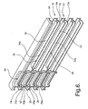
- Figure 6 is a perspective, staggered cross-sectional view of the evaporator shown in Figure 1, the cross section taken along an inlet manifold of the evaporator;
- Figure 7 is a side view of the cross-sectional view of Figure 6;
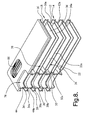
- Figure 8 is a perspective, staggered cross-sectional view of the evaporator shown in Figure 1, the cross-section taken along the outlet manifold;
- Figure 9 is a side view of the cross-sectional view of Figure 8;
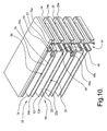
- Figure 10 is a perspective, partial cross-sectional view of the evaporator of Figure 1 taken along the return tank;
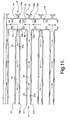
- Figure 11 is a side view of the cross-sectional view of Figure 10;
- Figure 12 is a perspective, broken cross-sectional view of the evaporator of Figure 1 extending along the length of the evaporator;
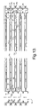
- Figure 13 is a side view of the cross-sectional view of Figure 12;
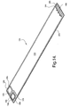
- Figure 14 is a perspective view of an alternate embodiment of a first plate;
- Figure 15 is an enlarged view from Figure 14 of a first end of the alternative first plate;
- Figure 16 is a perspective view of an alternative embodiment of the second plate;
- Figure 17 is an enlarged view from Figure 16 of a first end of the alternative second plate; and
- Figure 18 is a cross-sectional view of an embodiment of the invention showing fluid pathways arranged in an alternating pattern.
-
- Various embodiments of the invention are shown throughout the several figures. Similar structure can be defined by alternative embodiments of the invention. Similar structural elements share a common reference numeral and are differentiated with an alphabetic designation.
- Referring now to Figure 1, the present invention provides an
evaporator 10 including twofirst plates first plates first plates first plates first pair 14. The evaporator also includes twosecond plates second pair 18. Thefirst pair 14 ofplates second pair 18 ofplates - Referring now to Figures 2 and 6, each of the
first plates peripheral lip first plate first center portion peripheral lip peripheral lips first plates pair 14 is formed. Thecenter portions first pair 14 is formed, defining afirst cavity 24 between thefirst plates - Referring now to Figures 2, 10 and 11, each of the
first plates first return apertures first center portions return apertures first cavity 24. Each of the twofirst plates first return trough first center portion first return apertures respective bottoms first return troughs - Referring now to Figures 2, 3, and 6-8, each of the
first plates first inlet aperture 28 and afirst outlet aperture first center portion first return aperture first plates first inlet trough 58 recessed with respect to the respectivefirst center portion first inlet aperture 28 can be disposed in abottom 60 of thefirst inlet troughs 58. Eachplate secondary inlet aperture 88. Thesecondary inlet 88 aperture can be disposed in a bottom of aninlet trough 86. Referring now to Figures 14 and 15, an alternative embodiment of afirst plate 12b can include aperipheral lip 20b, acenter portion 22b, areturn aperture 26b disposed at thebottom 48b of aninlet trough 46b, and asingle inlet aperture 28b disposed at thebottom 60b of aninlet trough 58b. - Referring now to Figures 2, 3, 8, 9, 12 and 13, each of the
first plates first outlet trough first center portion first outlet apertures respective bottoms first outlet troughs first plate 12b can include anoutlet aperture 30b defined in abottom 70b of anoutlet trough 68b. - Referring now to Figures 2, 3 and 9, each of the
first plates mounds first center portions respective outlet apertures troughs mounds first plates first pair 14 can engage one another when thefirst pair 14 is formed. Themounds outlet apertures first cavity 24. Referring now to Figures 14 and 15, the alternative embodiment of afirst plate 12b can include amound 32b surrounding theoutlet aperture 30b. Themound 32b can surround thetrough 68b. - The
second plates first plates second plates peripheral lip second plates second center portions peripheral lips peripheral lips second plates second pair 18 is formed. Thesecond center portions second pair 18 is formed to define asecond cavity 38 between theplates second plate 16b can include a secondperipheral lip 34b extending along the periphery of thesecond plate 16b and a second center portion 36b recessed with respect to the secondperipheral lip 34b. - Referring now to Figures 4, 5 and 10-13, each of the
second plates second return aperture second center portion second return apertures second cavity 38. Each of the twosecond plates second return trough second center portion second return apertures respective bottoms second return troughs second plate 16b can include asecond return aperture 40b disposed at a bottom 52b of areturn trough 50b. - Referring now to Figures 4-8, each of the
second plates second inlet aperture 42 and asecond outlet aperture second center portion second return apertures plate second inlet trough 62 recessed with respect to the respectivesecond center portion second inlet aperture 42 can be individually disposed inrespective bottoms 64 of thesecond inlet trough 62. Eachplate secondary inlet aperture 92. Thesecondary inlet aperture 92 can be disposed in a bottom of aninlet trough 90. Referring now to Figures 16 and 17, the alternative embodiment of thesecond plate 16b can include asingle inlet aperture 42b disposed at a bottom 64b of aninlet trough 62b. - Referring now to Figures 4, 5, 8, 9, 12 and 13, each of the
second plates second outlet trough second center portion second outlet apertures respective bottoms second outlet troughs plate 16b can include asecond outlet aperture 44b disposed in a bottom 74b of asecond outlet trough 72b. - Referring now to Figures 4, 5 and 7, each of the
second plates second mound 56 individually projecting from the respectivesecond center portion second inlet aperture 42. Thesecond plates third mound 94 projecting from the respectivesecond center portion secondary inlet aperture 92. As shown in the drawings, themounds troughs pair 18, amound 56 of theplate 16 is engaged with a mound 94a of thesecond plate 16a in response to theplates mounds 56, 94a can be in sealing engagement with one another to isolate the alignedapertures Mounds apertures 42a and 92 from said second cavity (38). - A plurality of
pairs evaporator 10. Referring now to Figures 10, 11, and 13, the bottom 48 of thefirst return trough 46 can cooperate in sealing engaging with the bottom 52a of thesecond return trough 50a when thepairs plates return tank 54 in communication with the first andsecond cavities return tank 54 can be in fluid communication with all of the cavities formed by theevaporator 10. - Referring now to Figures 8, 9 and 13, the bottom 70 of the
first outlet trough 68 can cooperate in sealing engaging with the bottom 74a of thesecond outlet trough 72a betweenadjacent plates pairs plates outlet manifold 76 in communication with only thesecond cavity 38 relative to the first andsecond cavities - Referring now to Figure 7, the bottom 60 of the
inlet trough 58 can cooperate in sealing engaging with the bottom 98a of theinlet trough 90a betweenadjacent plates adjacent pairs plates inlet manifold 66 in communication with only thefirst cavity 24 relative to the first andsecond cavities second inlet manifold 96 can be defined by aligned apertures on an opposite side of theoutlet manifold 76. - Referring now to Figure 18, a plurality of
pairs pair 18a can be positioned betweenfirst pair 14a and athird pair 78. Thepair 78 can be identical to thepair 14a. Eachpair cavities plates evaporator 10 be directed through the cavities defined by thevarious pairs plates evaporator 10. For example, afirst fluid stream 80 can move in a first direction. Asecond fluid stream 82 can move in a second direction. Athird fluid stream 84 can move in the first direction. Thesecond fluid stream 82 can be disposed between the first and third fluid streams 80, 84. - In operation, a stream of fluid to be evaporated can be directed into
inlet manifolds evaporator 10. The stream can be divided into sub-streams; each sub-stream passing from the inlet manifolds 66, 96 tocavities 24 defined betweenfirst plates return tank 54 and re-divided to move intocavities 38 defined betweensecond plates outlet manifold 76 and the fluid stream can evacuate theevaporator 10. - The exemplary embodiment of the invention provides numerous advantages over the prior art. For example, the invention provides Improved Temperature Uniformity of Evaporator Discharge Air. Automotive evaporators operate such that they are not completely "flooded" with refrigerant. This means that somewhere toward the end of the refrigerant flow path, the refrigerant is completely evaporated. From this "dry point" to the outlet of the evaporator exists a region where the refrigerant is superheated. This superheated region of the evaporator becomes an area that that doesn't much cool the air flowing through it and thus results in a "hot spot" at air discharge face of the evaporator. Further, in recent years, automotive trend is away from Orifice Tube expansion devices toward Thermal Expansion Valves, which results in higher levels of superheat, thus aggravating the temperature uniformity issue. This invention, through it's alternating refrigerant flow arrangement, isolates these "hot spots" to a number of smaller areas instead of one bigger area, each surrounded by cold, flooded (inlet) evaporator tubes so that the resulting mixed air at the evaporator outlet is not so hot.
- Furthermore, the invention provides improved Cooling Capacity. With this invention, each particle of refrigerant makes only two passes through the evaporator vs. the more typical four or more passes on conventional evaporators. This should lower the refrigerant side pressure drop. And, since in the evaporator, refrigerant exists in the 2-phase state (except for superheated region), and since, the refrigerant temperature depends directly on the refrigerant pressure in the 2-phase state, this lower pressure drop directly affects the temperature of the refrigerant and thus it's capacity to cool and dehumidify the air. To explain further, since the pressure at the outlet of the evaporator is more or less fixed by the refrigerant controls to keep the evaporator from getting too cold and "freezing up", the lower pressure drop evaporator keeps the evaporator at a lower "mean evaporating temperature and pressure" therefore enhancing Cooling Capacity. There is another feature of this invention that similarly can enhance Cooling Capacity. Typical evaporators have identical individual refrigerant flow passages (tubes) in the evaporator. But since the refrigerant is evaporating, and thus increasing it's volumetric flow rate, as it flows through the evaporator, the ideal situation is to have an increasing area in the refrigerant flow direction―to reduce pressure drop. Since in this invention, the alternating passages can be different―one internal tube height for "inlet" tubes and another, larger, for "outlet" tubes―this feature also can reduce the refrigerant side pressure drop and enhance Cooling Capacity. Conventional evaporators accomplish this by varying the number of individual tubes in each refrigerant pass, a different technique than the feature of the invention just described.
- Furthermore, the invention provides improved Noise characteristics. It is well known that if air side pressure drop can be reduced, then noise can be reduced since fan power is reduced. One way air side pressure drop can be reduced, for any given evaporator size (exterior dimensions) is to increase the proportion of the face area open to the air flow. This invention can enhance this is two ways. The first is that, the smaller return manifold mentioned above that this alternating flow idea allows, means that less of the total face area normal to the flow of the air is blocked, allowing reduction in pressure drop. The second is that since, as mentioned above, the inlet tubes can be made smaller in height than the outlet tubes this smaller tube height creates less blockage to the air flow (in this case the invention allows the choice of also reducing air side pressure drop instead of refrigerant pressure drop or in any combination that optimizes the two for any specific application).
- Furthermore, the invention provides improved environmental characteristics. It has already been mentioned above that air side and refrigerant side pressure drop can be reduced with this invention. This also reduces power consumption and thus increases the efficiency of the air conditioning unit. Additionally, however, the ability to decrease the height of the refrigerant tubes can reduce the internal volume (refrigerant side volume) of the evaporator, thus allowing a modest reduction in the "charge" of refrigerant required for the vehicle air conditioning unit. This is a mass savings for the vehicle, and further, could be advantageous if the usage of refrigerant were to some day be limited due to environmental issues.
- Furthermore, the exemplary embodiment of this invention is of simple construction. The tube plates can be die struck and these tube plates form the manifolds and even can form the refrigerant control orifices in the manifolds, if needed. Contrast this with the recently introduced compact evaporators that have good temperature uniformity. These have two rows of extruded tubes, separate manifolds that are not common, and even have separate orifice pieces that must be placed in the manifolds. The potential refrigerant charge reduction mentioned above is also a direct cost reduction.
- While the invention has been described in connection with what is presently considered to be the most practical and preferred embodiment, it is to be understood that the invention is not to be limited to the disclosed embodiments but, on the contrary, is intended to cover various modifications and equivalent arrangements included within the spirit and scope of the appended claims, which scope is to be accorded the broadest interpretation so as to encompass all such modifications and equivalent structures as is permitted under the law.
Claims (20)
- An evaporator (10) comprising:two first plates (12, 12a, 12b), each having a first configuration, engaged in a back to back mirrored relationship to one another to form a first pair (14, 14a);two second plates (16, 16a, 16b), each having a second configuration, engaged in a back to back mirrored relationship to one another to form a second pair (18, 18a), said first pair (14, 14a) and said second pair (18, 18a) stacked together.
- The evaporator (10) of claim 1 wherein each of said two first plates (12, 12a, 12b) includes a first peripheral lip (20, 20a, 20b) extending along the periphery of said first plate (12, 12a, 12b) and a first center portion (22, 22a, 22b) recessed with respect to said peripheral lip (20, 20a, 20b), said peripheral lips (20, 20a, 20b) of said two first plates (12, 12a, 12b) engage one another, whereby said center portions (22, 22a, 22b) are spaced apart from one another defining a first cavity (24) therebetween.
- The evaporator (10) of claim 2 wherein each of said two first plates (12, 12a, 12b) includes a first return aperture (26, 26a, 26b) adjacent said first center portion (22, 22a, 22b) communicating with said first cavity (24).
- The evaporator (10) of claim 3 wherein the each of said two first plates (12, 12a, 12b) includes a first inlet aperture (28, 28a, 28b) and a first outlet aperture (30, 30a, 30b) disposed on an opposite side of said first center portion (22, 22a, 22b) relative to said first return aperture (26, 26a, 26b).
- The evaporator (10) of claim 4 wherein the each of said two first plates (12, 12a, 12b) includes at least one mound (32, 32a, 32b) projecting from said first center portion (22, 22a, 22b) and surrounding one of said first inlet aperture (28, 28a, 28b) and said first outlet aperture (30, 30a, 30b), said mounds (32, 32a, 32b) of said two first plates (12, 12a, 12b) of said first pair (14, 14a) engage one another, whereby said one aperture (28, 28a, 28b, 30, 30a, 30b) surrounded by said mound (32, 32a, 32b) is isolated from said first cavity (24).
- The evaporator (10) of claim 4 wherein each of said two second plates (16, 16a, 16b) includes a second peripheral lip (34, 34a, 34b) extending along the periphery of said second plate (16, 16a, 16b) and a second center portion (36, 36a, 36b) recessed with respect to said second peripheral lip (34, 34a, 34b), said peripheral lips (34, 34a, 34b) of said two second plates (16, 16a, 16b) engaged with one another, whereby said second central portions (36, 36a, 36b) are spaced apart from one another defining a second cavity (38) therebetween, each of said two second plates (16, 16a, 16b) also including a second return aperture (40, 40a, 40b) adjacent said second center portion (36, 36a, 36b), said second return apertures (40, 40a, 40b) communicating with said second cavity (38), each of said two second plates (16, 16a, 16b) also including a second inlet aperture (42, 42a, 42b) and a second outlet aperture (44, 44a, 44b) disposed on an opposite side of said second center portion (36, 36a, 36b) relative to said second return aperture (40, 40a, 40b).
- The evaporator (10) of claim 6 wherein:each of said two first plates (12, 12a) includes a first return trough (46, 46a) recessed with respect to said first center portion (22, 22a), said first return aperture (26, 26a) disposed at a bottom (48, 48a) of said first return trough (46, 46a); andeach of said two second plates (16, 16a) includes a second return trough (50, 50a) recessed with respect to said second center portion (36, 36a), said second return aperture (40, 40a) disposed at a bottom (52, 52a) of said second return trough (50, 50a), said bottom (48, 48a) of said first return trough (46, 46a) engaging said bottom (52, 52a) of said second return trough (50, 50a) between adjacent pairs (14, 14a, 18, 18a) of plates, whereby said return apertures (26, 26a, 40, 40a) of the plates (12, 12a, 16, 16a) are aligned to define a return tank (54) in communication with the first and second cavities (24, 38).
- The evaporator (10) of claim 7 wherein:each of said two first plates (12, 12a) includes a first mound (32, 32a) projecting from said first center portion (22, 22a) and surrounding said first outlet aperture, said first mounds of said two first plates (12, 12a) engaged with one another, whereby said first outlet aperture (30, 30a) is isolated from said first cavity (24); andeach of said two second plates (16, 16a) includes a second mound (56, 56a, 56b) projecting from said second center portion (36, 36a, 36b) and surrounding said second inlet aperture (42, 42a, 42b), said second mounds (56, 56a) of said two second plates (16, 16a) engaged with one another, whereby said second inlet aperture (42, 42a) is isolated from said second cavity (38).
- The evaporator (10) of claim 8 wherein:each of said two first plates (12, 12a, 12b) includes a first inlet trough (58, 58a, 58b, 86, 86a) recessed with respect to said first center portion (22, 22a, 22b), said first inlet aperture (28, 28a, 28b, 88, 88a) disposed at a bottom (60, 60a, 60b, 87, 87a) of said first inlet trough (58, 58a, 58b, 86, 86a); andeach of said two second plates (16, 16a, 16b) includes a second inlet trough (62, 62a, 62b, 90, 90a) recessed with respect to said second center portion (36, 36a, 36b), said second inlet aperture (42, 42a, 42b, 92, 92a) disposed at a bottom (64, 64a, 64b, 98, 98a) of said second inlet trough (62, 62a, 62b, 90, 90a), said bottom of (60, 60a, 60b, 87, 87a) said first inlet trough (58, 58a, 58b, 86, 86a) engaging said bottom (64, 64a, 64b, 98, 98a) of said second inlet trough (62, 62a, 62b, 90, 90a) between adjacent pairs of plates, whereby said inlet apertures (28, 28a, 42, 42a, 86, 86a, 92, 92a) of the plates (12, 12a, 16, 16a) are aligned to define an inlet manifold (66, 96) in communication with only the first cavity (24) relative to the first and second cavities (24, 38).
- The evaporator (10) of claim 8 wherein:each of said two first plates (12, 12a, 12b) includes a first outlet trough (68, 68a, 68b) recessed with respect to said first center portion (22, 22a, 22b), said first outlet aperture (30, 30a, 30b) disposed at a bottom (70, 70a, 70b) of said first outlet trough (68, 68a, 68b); andeach of said two second plates (16, 16a, 16b) includes a second outlet trough (72, 72a, 72b) recessed with respect to said second center portion (36, 36a, 36b), said second outlet aperture (44, 44a, 44b) disposed at a bottom (74, 74a, 74b) of said second outlet trough (72, 72a, 72b), said bottom (70) of said first outlet trough (68) engaging said bottom (74a) of said second outlet trough (72a) between adjacent pairs (14, 14a, 18, 18a) of plates (12, 16a), whereby said outlet apertures (30, 30a, 44, 44a) of the plates (12, 12a, 16, 16a) are aligned to define a outlet manifold (76) in communication with only the second cavity (38) relative to the first and second cavities (24, 38).
- The evaporator (10) of claim 10 including:a third pair (78) formed with said two first plates (12c, 12d) engaged in a back to back mirrored relationship to one another, said third pair (78) stacked with said first and second pairs (14a, 18a) such that said second pair (18a) is disposed between said first and third pairs (14a, 78).
- A method for manufacturing an evaporator (10) comprising the steps of:engaging two first plates (12, 12a, 12b), each having a first configuration, in a back to back mirrored relationship to one another to form a first pair (14, 14a);engaging two second plates (16, 16a, 16b), each having a second configuration, in a back to back mirrored relationship to one another to form a second pair (18, 18a); andstacking said first pair (14) and said second pair (18).
- The method of claim 12 including:engaging another two said first plates (12c, 12d) in a back to back mirrored relationship to one another to form a third pair (78); andstacking said third pair (78) and said second pair (18a) whereby said second pair (18a) is disposed between said first and third pairs (14a, 78).
- The method of claim 13 including:directing a first fluid stream (80) in a first direction between said two first plates of said first pair (14a);directing a second fluid stream (82) in a second direction between said two second plates of said second pair (18a), wherein said first direction is opposite of said second direction; anddirecting a third fluid stream (84) in said first direction between said two plates of said third pair (78).
- The method of claim 12 including:forming said first plate (12, 12a, 12b) with a first peripheral lip (20, 20a, 20b) extending along the periphery of said first plate (12, 12a, 12b), a first center portion (22, 22a, 22b) recessed with respect to said first peripheral lip (20, 20a, 20b) and having first and second ends, a first return trough (46, 46a, 46b) recessed with respect to said center portion (22, 22a, 22b) and having a first return aperture (26, 26a, 26b) disposed in said first return trough (46, 46a, 46b), a first inlet trough (58, 58a, 58b) adjacent said second end and recessed with respect to said first center portion (22, 22a, 22b) with a first inlet aperture (28, 28a, 28b) disposed in said first inlet trough (58, 58a, 58b), a first outlet trough (68, 68a, 68b) adjacent said first inlet trough (58, 58a, 58b) and recessed with respect to said first center portion (22, 22a, 22b)with a first outlet aperture (30, 30a, 30b) disposed in said first outlet trough (68, 68a, 68b), and a first mound (32, 32a, 32b) projecting from said first center portion (22, 22a, 22b)and surrounding said first outlet trough (68, 68a, 68b).
- The method of claim 15 wherein said step of engaging two first plates (12, 12a, 12b) is further defined as engaging said first peripheral lips (20, 20a, 20b) of said two first plates (12, 12a, 12b) with one another and said first mounds (32, 32a, 32b) thereof with one another, whereby said first return apertures (26, 26a, 26b), said first inlet apertures (28, 28a, 28b) and said first outlet apertures (30, 30a, 30b) thereof are aligned.
- The method of claim 16 including:forming said second plate (16, 16a, 16b) wherein said second plate (16, 16a, 16b) includes a second peripheral lip (34, 34a, 34b) extending along the periphery of said second plate (16, 16a, 16b), a second center portion (36, 36a, 36b) recessed with respect to said second peripheral lip (34, 34a, 34b) and having first and second ends, a second return trough (50, 50a, 50b) recessed with respect to said second center portion (36, 36a, 36b) and having a second return aperture (40, 40a, 40b) disposed in said second return trough (50, 50a, 50b), a second inlet trough (62, 62a, 62b) adjacent said second end and recessed with respect to said second center portion (36, 36a, 36b) with a second inlet aperture (42, 42a, 42b) disposed in said second inlet trough (62, 62a, 62b), a second outlet trough (72, 72a, 72b) adjacent said second inlet trough (62, 62a, 62b) and recessed with respect to said second center portion (36, 36a, 36b) with a second outlet aperture (44, 44a, 44b) disposed in said second outlet trough (72, 72a, 72b), and a second mound (56, 56a, 56b) projecting from said second center portion (36, 36a, 36b) and surrounding said second inlet trough (62, 62a, 62b).
- The method of claim 17 wherein said step of engaging two second plates (16, 16a, 16b) is further defined as engaging said second peripheral lips (34, 34a, 34b) of said two second plates (16, 16a, 16b) with one another and said second mounds (56, 56a, 56b) thereof with one another, whereby said second return apertures (40, 40a, 40b), said second inlet apertures (42, 42a, 42b) and said outlet second apertures (44, 44a, 44b) thereof are aligned.
- The method of claim 18 wherein said step of stacking said first pair (14, 14a) and said second pair (18, 18a) is further defined as:engaging a bottom (48, 48a, 48b) of said first return trough (46, 46a, 46b) of one of said first plates (12, 12a, 12b) with a bottom (52, 52a, 52b) of said second return trough (50, 50a, 50b) of an adjacent second plate (16, 16a, 16b);engaging a bottom (60, 60a, 60b) of said first inlet trough (58, 58a, 58b) of said first plate (12, 12a, 12b) with a bottom (64, 64a, 64b) of said second inlet trough (62, 62a, 62b) of said adjacent second plate (16, 16a, 16b); andengaging a bottom (70, 70a, 70b) of said first outlet trough (68, 68a, 68b) of said first plate (12, 12a, 12b) with a bottom (74, 74a, 74b) of said second outlet trough (72, 72a, 72b) of said adjacent second plate (16, 16a, 16b).
- An evaporator (10) comprising:a first plate (12, 12a) including a first peripheral lip (20, 20a) extending along the periphery of said first plate (12, 12a), a first center portion (22, 22a) recessed with respect to said lip (20, 20a) and having first and second ends, and a width, a first return trough (46, 46a) recessed with respect to said center portion (22, 22a) and having a first return aperture (26, 26a) positioned at a bottom (48, 48a) of said first return trough (46, 46a), first and second inlet troughs (58, 58a, 86) adjacent said second end and recessed with respect to said center portion (22, 22a) with inlet apertures (28, 28a, 88) disposed in each inlet trough (58, 58a, 86), a first outlet trough (68, 68a) disposed between said first and second inlet troughs (58, 58a, 86) and recessed with respect to said center portion (22, 22a) with an outlet aperture (30, 30a) disposed in said outlet trough (68, 68a), and a first mound (32, 32a) projecting from said center portion (22, 22a) and surrounding said outlet trough (68, 68a);a second plate (16, 16a) including a second peripheral lip (34, 34a) extending along the periphery of said second plate (16, 16a), a second center portion (36, 36a) recessed with respect to said second lip(34, 34a) and having third and fourth ends, and a second width, a second return trough (50, 50a) recessed with respect to said second center portion (36, 36a) and having a second return aperture (40, 40a) positioned at a bottom (52, 52a) of said second return trough (50, 50a), third and fourth inlet troughs (62, 62a, 90) adjacent said fourth end and recessed with respect to said second center portion (36, 36a) with inlet apertures (42, 42a, 92) disposed in each inlet trough (62, 62a, 90), a second outlet trough (72, 72a) disposed between said third and fourth inlet troughs (62, 62a, 90) and recessed with respect to said second center portion (36, 36a) with a second outlet aperture (44, 44a) disposed in said second outlet trough (72, 72a), a second mound (56, 56a) projecting from said second center portion (36, 36a) and surrounding said third inlet trough (62, 62a), and a third mound (94) projecting from said second center portion (36, 36a) and surrounding said fourth inlet trough (88);a pair (14, 14a) of first plates (12, 12a) disposed in a back to back mirrored relationship to one another with said peripheral lips (20, 20a) thereof engaging one another and said first mounds (32, 32a) thereof engaging one another, whereby said return apertures (26, 26a), said inlet apertures (28, 28a) and said outlet apertures (30, 30a) thereof are aligned;a pair (18, 18a) of second plates (16, 16a) disposed in a back to back mirrored relationship to one another with said peripheral lips (34, 34a) thereof engaging one another and said second and third mounds (56, 56a, 94) thereof engaging one another, whereby said return apertures (40, 40a), said inlet apertures (42, 42a) and said outlet apertures (44, 44a) thereof are aligned; andsaid pairs (14, 14a, 18, 18a) being alternatingly stacked with respect to one another with said first and second return troughs (46, 46a, 50, 50a) engaging one another whereby said return apertures (26, 26a, 40, 40a) are aligned to define a return tank (54), said inlet troughs (58, 58a, 62, 62a, 86, 90) engaging one another whereby said inlet apertures (28, 28a, 42, 42a, 88, 92) are aligned to define a first and second inlet manifolds (66, 96), and said outlet troughs (68, 68a, 72, 72a) engaging one another whereby said outlet apertures (30, 30a, 44, 44a) are aligned to define an outlet manifold (76), and whereby said center portions (22, 22a) of said pair (14, 14a) of first plates (12, 12a, 12b) are spaced apart to define a fluid pathway (24) communicating with the return tank (54) and the first and second inlet manifolds (66, 96) and said center portions (36, 36a) of said pair (18, 18a) of second plates (16, 16a, 16b) are spaced apart to define a fluid pathway (38) communicating with the return tank (54) and the outlet manifold (76).
Applications Claiming Priority (2)
| Application Number | Priority Date | Filing Date | Title |
|---|---|---|---|
| US10/752,976 US7080526B2 (en) | 2004-01-07 | 2004-01-07 | Full plate, alternating layered refrigerant flow evaporator |
| US752976 | 2004-01-07 |
Publications (2)
| Publication Number | Publication Date |
|---|---|
| EP1553370A1 true EP1553370A1 (en) | 2005-07-13 |
| EP1553370B1 EP1553370B1 (en) | 2017-04-12 |
Family
ID=34592568
Family Applications (1)
| Application Number | Title | Priority Date | Filing Date |
|---|---|---|---|
| EP04078471.2A Expired - Lifetime EP1553370B1 (en) | 2004-01-07 | 2004-12-22 | Full plate alternating layered refrigerant flow evaporator |
Country Status (2)
| Country | Link |
|---|---|
| US (1) | US7080526B2 (en) |
| EP (1) | EP1553370B1 (en) |
Cited By (3)
| Publication number | Priority date | Publication date | Assignee | Title |
|---|---|---|---|---|
| DE102005050738A1 (en) * | 2005-10-22 | 2007-04-26 | Modine Manufacturing Co., Racine | Plate-type heat exchanger for air cooling has aperture edges in at least first part of connection plate with deformations forming part of inflow and outflow channels |
| EP1901020A3 (en) * | 2006-09-15 | 2013-04-10 | Behr GmbH & Co. KG | Stacked plate heat exchanger for charge air cooling |
| WO2018206668A1 (en) * | 2017-05-10 | 2018-11-15 | Valeo Systemes Thermiques | Optimized heat exchanger having three rows of tubes |
Families Citing this family (12)
| Publication number | Priority date | Publication date | Assignee | Title |
|---|---|---|---|---|
| US7195060B2 (en) * | 2005-04-01 | 2007-03-27 | Dana Canada Corporation | Stacked-tube heat exchanger |
| WO2008064251A2 (en) * | 2006-11-22 | 2008-05-29 | Johnson Controls Technology Company | Space-saving multichannel heat exchanger |
| WO2008064219A1 (en) * | 2006-11-22 | 2008-05-29 | Johnson Controls Technology Company | Multichannel evaporator with flow mixing manifold |
| WO2008064247A1 (en) * | 2006-11-22 | 2008-05-29 | Johnson Controls Technology Company | Multi-function multichannel heat exchanger |
| US8166776B2 (en) * | 2007-07-27 | 2012-05-01 | Johnson Controls Technology Company | Multichannel heat exchanger |
| US20090025405A1 (en) * | 2007-07-27 | 2009-01-29 | Johnson Controls Technology Company | Economized Vapor Compression Circuit |
| EP2193315B1 (en) * | 2007-08-24 | 2011-10-12 | Johnson Controls Technology Company | A vapor compression system and method of controlling it |
| DE102011090176A1 (en) * | 2011-12-30 | 2013-07-04 | Behr Gmbh & Co. Kg | Heat exchanger |
| DE102011090188A1 (en) * | 2011-12-30 | 2013-07-04 | Behr Gmbh & Co. Kg | Heat exchanger |
| DE102015107427A1 (en) * | 2015-05-12 | 2016-11-17 | Benteler Automobiltechnik Gmbh | Automotive heat exchanger system |
| WO2019131571A1 (en) * | 2017-12-27 | 2019-07-04 | 株式会社ティラド | Header plateless type heat exchanger |
| DE102024104217A1 (en) * | 2024-02-15 | 2025-08-21 | Mahle International Gmbh | Heat exchanger comprising plates |
Citations (5)
| Publication number | Priority date | Publication date | Assignee | Title |
|---|---|---|---|---|
| US4002201A (en) * | 1974-05-24 | 1977-01-11 | Borg-Warner Corporation | Multiple fluid stacked plate heat exchanger |
| US4270602A (en) * | 1978-08-30 | 1981-06-02 | The Garrett Corporation | Heat exchanger |
| US5678419A (en) * | 1994-07-05 | 1997-10-21 | Nippondenso Co., Ltd | Evaporator for a refrigerating system |
| EP1160530A1 (en) * | 1999-03-04 | 2001-12-05 | Ebara Corporation | Plate type heat exchanger |
| US20020079093A1 (en) * | 2000-10-10 | 2002-06-27 | Xiaoyang Rong | Heat exchangers with flow distributing orifice partitions |
Family Cites Families (30)
| Publication number | Priority date | Publication date | Assignee | Title |
|---|---|---|---|---|
| US20521A (en) * | 1858-06-08 | Smut-machine | ||
| US70797A (en) * | 1867-11-12 | of cleveland | ||
| US79093A (en) * | 1868-06-23 | woodbuet | ||
| US2462421A (en) * | 1944-10-26 | 1949-02-22 | Solar Aircraft Co | Crossflow heat exchanger |
| GB1312292A (en) * | 1970-03-04 | 1973-04-04 | Maxwell Davidson Evaporators | Evaporators |
| DE2340003A1 (en) * | 1973-08-07 | 1975-02-20 | Linde Ag | DEFOGGER |
| US3984281A (en) | 1975-01-09 | 1976-10-05 | Henry Balfour & Company Limited | Plate type liquid heater and evaporator |
| US4619242A (en) * | 1978-10-10 | 1986-10-28 | Smith Robert J | Heat transfer and conditioning unit |
| SE426653B (en) | 1980-12-08 | 1983-02-07 | Alfa Laval Ab | Plate evaporator |
| SE424143B (en) | 1980-12-08 | 1982-07-05 | Alfa Laval Ab | Plate evaporator |
| JPS57140601A (en) * | 1981-02-25 | 1982-08-31 | Diesel Kiki Co Ltd | Laminate type evaporator |
| DE3147378C2 (en) * | 1981-11-30 | 1985-05-23 | Johs. Burmester & Co GmbH, 2054 Geesthacht | Falling film evaporator plate for a refrigeration system |
| DE3220774C2 (en) | 1982-06-02 | 1986-09-25 | W. Schmidt GmbH & Co KG, 7518 Bretten | Plate evaporator or condenser |
| SE8402163D0 (en) * | 1984-04-18 | 1984-04-18 | Alfa Laval Food & Dairy Eng | HEAT EXCHANGER OF FALL MOVIE TYPE |
| JPS6113178U (en) * | 1984-06-28 | 1986-01-25 | 株式会社 土屋製作所 | housingless heat exchanger |
| JP2646580B2 (en) | 1986-12-11 | 1997-08-27 | 株式会社デンソー | Refrigerant evaporator |
| DE69016119T2 (en) * | 1989-07-19 | 1995-08-31 | Showa Aluminum Corp | Heat pipe. |
| US5172759A (en) * | 1989-10-31 | 1992-12-22 | Nippondenso Co., Ltd. | Plate-type refrigerant evaporator |
| JP2917764B2 (en) * | 1992-09-17 | 1999-07-12 | 株式会社デンソー | Evaporator for cooling system |
| CN1109232C (en) * | 1993-12-28 | 2003-05-21 | 昭和电工株式会社 | Plate heat exchanger |
| US5435383A (en) * | 1994-02-01 | 1995-07-25 | Rajagopal; Ramesh | Plate heat exchanger assembly |
| US5462113A (en) * | 1994-06-20 | 1995-10-31 | Flatplate, Inc. | Three-circuit stacked plate heat exchanger |
| DE4426692C1 (en) | 1994-07-28 | 1995-09-14 | Daimler Benz Ag | Vaporiser for transporting load of reactant mass flow |
| JP3635715B2 (en) * | 1994-10-07 | 2005-04-06 | 株式会社デンソー | Evaporator for air conditioner |
| JP2934392B2 (en) * | 1995-02-07 | 1999-08-16 | サンデン株式会社 | Heat exchanger |
| JPH09113171A (en) * | 1995-10-19 | 1997-05-02 | Showa Alum Corp | Stacked heat exchanger |
| JP3899444B2 (en) * | 1997-03-25 | 2007-03-28 | 三菱電機株式会社 | Cooling system |
| JP3629900B2 (en) * | 1997-07-04 | 2005-03-16 | 株式会社デンソー | Heat exchanger |
| US6536517B2 (en) | 2000-06-26 | 2003-03-25 | Showa Denko K.K. | Evaporator |
| JP2002107004A (en) | 2000-09-27 | 2002-04-10 | Calsonic Kansei Corp | Stacked type evaporator |
-
2004
- 2004-01-07 US US10/752,976 patent/US7080526B2/en not_active Expired - Lifetime
- 2004-12-22 EP EP04078471.2A patent/EP1553370B1/en not_active Expired - Lifetime
Patent Citations (5)
| Publication number | Priority date | Publication date | Assignee | Title |
|---|---|---|---|---|
| US4002201A (en) * | 1974-05-24 | 1977-01-11 | Borg-Warner Corporation | Multiple fluid stacked plate heat exchanger |
| US4270602A (en) * | 1978-08-30 | 1981-06-02 | The Garrett Corporation | Heat exchanger |
| US5678419A (en) * | 1994-07-05 | 1997-10-21 | Nippondenso Co., Ltd | Evaporator for a refrigerating system |
| EP1160530A1 (en) * | 1999-03-04 | 2001-12-05 | Ebara Corporation | Plate type heat exchanger |
| US20020079093A1 (en) * | 2000-10-10 | 2002-06-27 | Xiaoyang Rong | Heat exchangers with flow distributing orifice partitions |
Cited By (4)
| Publication number | Priority date | Publication date | Assignee | Title |
|---|---|---|---|---|
| DE102005050738A1 (en) * | 2005-10-22 | 2007-04-26 | Modine Manufacturing Co., Racine | Plate-type heat exchanger for air cooling has aperture edges in at least first part of connection plate with deformations forming part of inflow and outflow channels |
| EP1901020A3 (en) * | 2006-09-15 | 2013-04-10 | Behr GmbH & Co. KG | Stacked plate heat exchanger for charge air cooling |
| WO2018206668A1 (en) * | 2017-05-10 | 2018-11-15 | Valeo Systemes Thermiques | Optimized heat exchanger having three rows of tubes |
| FR3066261A1 (en) * | 2017-05-10 | 2018-11-16 | Valeo Systemes Thermiques | HEAT EXCHANGER OPTIMIZED WITH THREE ROWS OF TUBES |
Also Published As
| Publication number | Publication date |
|---|---|
| EP1553370B1 (en) | 2017-04-12 |
| US7080526B2 (en) | 2006-07-25 |
| US20050144978A1 (en) | 2005-07-07 |
Similar Documents
| Publication | Publication Date | Title |
|---|---|---|
| US7080526B2 (en) | Full plate, alternating layered refrigerant flow evaporator | |
| US6688137B1 (en) | Plate heat exchanger with a two-phase flow distributor | |
| AU2002238890B2 (en) | Layered heat exchanger, layered evaporator for motor vehicle air conditioners and refrigeration system | |
| CN102980328B (en) | Plate type heat exchanger | |
| US5479985A (en) | Heat exchanger | |
| EP1495277B1 (en) | Heat exchanger inlet tube with flow distributing turbulizer | |
| US20060054310A1 (en) | Evaporator using micro-channel tubes | |
| US5099913A (en) | Tubular plate pass for heat exchanger with high volume gas expansion side | |
| AU2002238890A1 (en) | Layered heat exchanger, layered evaporator for motor vehicle air conditioners and refrigeration system | |
| CN100373122C (en) | Layered type evaporator for motor vehicle air conditioner, etc., layered type heat exchanger for providing the same, and refrigeration cycle system including the same | |
| KR20160131577A (en) | Heat exchanger for air conditioner | |
| US20080078537A1 (en) | Multi-zone heat exchangers with separated manifolds | |
| US12013188B2 (en) | Shell-and-plate type heat exchanger | |
| US20140374072A1 (en) | Kit for a heat exchanger, a heat exchanger core, and heat exchanger | |
| US12123653B2 (en) | Heat exchanger | |
| WO2020217271A1 (en) | Refrigerant distributor, heat exchanger, and refrigeration cycle device | |
| JP7683025B2 (en) | Cooler including two substantially parallel flow chambers and three substantially parallel plates | |
| JPH06194001A (en) | Refrigerant evaporator | |
| JP3633030B2 (en) | Evaporator for air conditioner | |
| JP5674376B2 (en) | Evaporator | |
| KR20240097098A (en) | Evaporative Condensor | |
| CN223290621U (en) | Integrated heat exchanger, thermal management system and vehicle including the same | |
| JPH02171591A (en) | Laminated heat exchanger | |
| CN100513964C (en) | Heat exchanger | |
| JP2006038429A (en) | Evaporator |
Legal Events
| Date | Code | Title | Description |
|---|---|---|---|
| PUAI | Public reference made under article 153(3) epc to a published international application that has entered the european phase |
Free format text: ORIGINAL CODE: 0009012 |
|
| AK | Designated contracting states |
Kind code of ref document: A1 Designated state(s): AT BE BG CH CY CZ DE DK EE ES FI FR GB GR HU IE IS IT LI LT LU MC NL PL PT RO SE SI SK TR |
|
| AX | Request for extension of the european patent |
Extension state: AL BA HR LV MK YU |
|
| 17P | Request for examination filed |
Effective date: 20060113 |
|
| AKX | Designation fees paid |
Designated state(s): AT BE BG CH CY CZ DE DK EE ES FI FR GB GR HU IE IS IT LI LT LU MC NL PL PT RO SE SI SK TR |
|
| 17Q | First examination report despatched |
Effective date: 20070604 |
|
| RAP1 | Party data changed (applicant data changed or rights of an application transferred) |
Owner name: MAHLE INTERNATIONAL GMBH |
|
| GRAP | Despatch of communication of intention to grant a patent |
Free format text: ORIGINAL CODE: EPIDOSNIGR1 |
|
| INTG | Intention to grant announced |
Effective date: 20161213 |
|
| GRAS | Grant fee paid |
Free format text: ORIGINAL CODE: EPIDOSNIGR3 |
|
| GRAA | (expected) grant |
Free format text: ORIGINAL CODE: 0009210 |
|
| AK | Designated contracting states |
Kind code of ref document: B1 Designated state(s): AT BE BG CH CY CZ DE DK EE ES FI FR GB GR HU IE IS IT LI LT LU MC NL PL PT RO SE SI SK TR |
|
| REG | Reference to a national code |
Ref country code: GB Ref legal event code: FG4D |
|
| REG | Reference to a national code |
Ref country code: CH Ref legal event code: EP |
|
| REG | Reference to a national code |
Ref country code: IE Ref legal event code: FG4D |
|
| REG | Reference to a national code |
Ref country code: AT Ref legal event code: REF Ref document number: 884336 Country of ref document: AT Kind code of ref document: T Effective date: 20170515 |
|
| REG | Reference to a national code |
Ref country code: DE Ref legal event code: R096 Ref document number: 602004051068 Country of ref document: DE |
|
| REG | Reference to a national code |
Ref country code: NL Ref legal event code: MP Effective date: 20170412 |
|
| REG | Reference to a national code |
Ref country code: LT Ref legal event code: MG4D |
|
| REG | Reference to a national code |
Ref country code: AT Ref legal event code: MK05 Ref document number: 884336 Country of ref document: AT Kind code of ref document: T Effective date: 20170412 |
|
| PG25 | Lapsed in a contracting state [announced via postgrant information from national office to epo] |
Ref country code: NL Free format text: LAPSE BECAUSE OF FAILURE TO SUBMIT A TRANSLATION OF THE DESCRIPTION OR TO PAY THE FEE WITHIN THE PRESCRIBED TIME-LIMIT Effective date: 20170412 |
|
| PG25 | Lapsed in a contracting state [announced via postgrant information from national office to epo] |
Ref country code: GR Free format text: LAPSE BECAUSE OF FAILURE TO SUBMIT A TRANSLATION OF THE DESCRIPTION OR TO PAY THE FEE WITHIN THE PRESCRIBED TIME-LIMIT Effective date: 20170713 Ref country code: LT Free format text: LAPSE BECAUSE OF FAILURE TO SUBMIT A TRANSLATION OF THE DESCRIPTION OR TO PAY THE FEE WITHIN THE PRESCRIBED TIME-LIMIT Effective date: 20170412 Ref country code: FI Free format text: LAPSE BECAUSE OF FAILURE TO SUBMIT A TRANSLATION OF THE DESCRIPTION OR TO PAY THE FEE WITHIN THE PRESCRIBED TIME-LIMIT Effective date: 20170412 Ref country code: ES Free format text: LAPSE BECAUSE OF FAILURE TO SUBMIT A TRANSLATION OF THE DESCRIPTION OR TO PAY THE FEE WITHIN THE PRESCRIBED TIME-LIMIT Effective date: 20170412 Ref country code: AT Free format text: LAPSE BECAUSE OF FAILURE TO SUBMIT A TRANSLATION OF THE DESCRIPTION OR TO PAY THE FEE WITHIN THE PRESCRIBED TIME-LIMIT Effective date: 20170412 |
|
| PG25 | Lapsed in a contracting state [announced via postgrant information from national office to epo] |
Ref country code: IS Free format text: LAPSE BECAUSE OF FAILURE TO SUBMIT A TRANSLATION OF THE DESCRIPTION OR TO PAY THE FEE WITHIN THE PRESCRIBED TIME-LIMIT Effective date: 20170812 Ref country code: PL Free format text: LAPSE BECAUSE OF FAILURE TO SUBMIT A TRANSLATION OF THE DESCRIPTION OR TO PAY THE FEE WITHIN THE PRESCRIBED TIME-LIMIT Effective date: 20170412 Ref country code: SE Free format text: LAPSE BECAUSE OF FAILURE TO SUBMIT A TRANSLATION OF THE DESCRIPTION OR TO PAY THE FEE WITHIN THE PRESCRIBED TIME-LIMIT Effective date: 20170412 Ref country code: BG Free format text: LAPSE BECAUSE OF FAILURE TO SUBMIT A TRANSLATION OF THE DESCRIPTION OR TO PAY THE FEE WITHIN THE PRESCRIBED TIME-LIMIT Effective date: 20170712 |
|
| REG | Reference to a national code |
Ref country code: FR Ref legal event code: PLFP Year of fee payment: 14 |
|
| REG | Reference to a national code |
Ref country code: DE Ref legal event code: R097 Ref document number: 602004051068 Country of ref document: DE |
|
| PG25 | Lapsed in a contracting state [announced via postgrant information from national office to epo] |
Ref country code: CZ Free format text: LAPSE BECAUSE OF FAILURE TO SUBMIT A TRANSLATION OF THE DESCRIPTION OR TO PAY THE FEE WITHIN THE PRESCRIBED TIME-LIMIT Effective date: 20170412 Ref country code: SK Free format text: LAPSE BECAUSE OF FAILURE TO SUBMIT A TRANSLATION OF THE DESCRIPTION OR TO PAY THE FEE WITHIN THE PRESCRIBED TIME-LIMIT Effective date: 20170412 Ref country code: DK Free format text: LAPSE BECAUSE OF FAILURE TO SUBMIT A TRANSLATION OF THE DESCRIPTION OR TO PAY THE FEE WITHIN THE PRESCRIBED TIME-LIMIT Effective date: 20170412 Ref country code: EE Free format text: LAPSE BECAUSE OF FAILURE TO SUBMIT A TRANSLATION OF THE DESCRIPTION OR TO PAY THE FEE WITHIN THE PRESCRIBED TIME-LIMIT Effective date: 20170412 Ref country code: RO Free format text: LAPSE BECAUSE OF FAILURE TO SUBMIT A TRANSLATION OF THE DESCRIPTION OR TO PAY THE FEE WITHIN THE PRESCRIBED TIME-LIMIT Effective date: 20170412 |
|
| PLBE | No opposition filed within time limit |
Free format text: ORIGINAL CODE: 0009261 |
|
| STAA | Information on the status of an ep patent application or granted ep patent |
Free format text: STATUS: NO OPPOSITION FILED WITHIN TIME LIMIT |
|
| PG25 | Lapsed in a contracting state [announced via postgrant information from national office to epo] |
Ref country code: IT Free format text: LAPSE BECAUSE OF FAILURE TO SUBMIT A TRANSLATION OF THE DESCRIPTION OR TO PAY THE FEE WITHIN THE PRESCRIBED TIME-LIMIT Effective date: 20170412 |
|
| 26N | No opposition filed |
Effective date: 20180115 |
|
| PG25 | Lapsed in a contracting state [announced via postgrant information from national office to epo] |
Ref country code: SI Free format text: LAPSE BECAUSE OF FAILURE TO SUBMIT A TRANSLATION OF THE DESCRIPTION OR TO PAY THE FEE WITHIN THE PRESCRIBED TIME-LIMIT Effective date: 20170412 |
|
| REG | Reference to a national code |
Ref country code: CH Ref legal event code: PL |
|
| GBPC | Gb: european patent ceased through non-payment of renewal fee |
Effective date: 20171222 |
|
| REG | Reference to a national code |
Ref country code: IE Ref legal event code: MM4A |
|
| PG25 | Lapsed in a contracting state [announced via postgrant information from national office to epo] |
Ref country code: LU Free format text: LAPSE BECAUSE OF NON-PAYMENT OF DUE FEES Effective date: 20171222 |
|
| REG | Reference to a national code |
Ref country code: BE Ref legal event code: MM Effective date: 20171231 |
|
| PG25 | Lapsed in a contracting state [announced via postgrant information from national office to epo] |
Ref country code: IE Free format text: LAPSE BECAUSE OF NON-PAYMENT OF DUE FEES Effective date: 20171222 |
|
| PG25 | Lapsed in a contracting state [announced via postgrant information from national office to epo] |
Ref country code: CH Free format text: LAPSE BECAUSE OF NON-PAYMENT OF DUE FEES Effective date: 20171231 Ref country code: GB Free format text: LAPSE BECAUSE OF NON-PAYMENT OF DUE FEES Effective date: 20171222 Ref country code: BE Free format text: LAPSE BECAUSE OF NON-PAYMENT OF DUE FEES Effective date: 20171231 Ref country code: LI Free format text: LAPSE BECAUSE OF NON-PAYMENT OF DUE FEES Effective date: 20171231 |
|
| PGFP | Annual fee paid to national office [announced via postgrant information from national office to epo] |
Ref country code: FR Payment date: 20181227 Year of fee payment: 15 |
|
| PGFP | Annual fee paid to national office [announced via postgrant information from national office to epo] |
Ref country code: DE Payment date: 20190228 Year of fee payment: 15 |
|
| PG25 | Lapsed in a contracting state [announced via postgrant information from national office to epo] |
Ref country code: MC Free format text: LAPSE BECAUSE OF FAILURE TO SUBMIT A TRANSLATION OF THE DESCRIPTION OR TO PAY THE FEE WITHIN THE PRESCRIBED TIME-LIMIT Effective date: 20170412 Ref country code: HU Free format text: LAPSE BECAUSE OF FAILURE TO SUBMIT A TRANSLATION OF THE DESCRIPTION OR TO PAY THE FEE WITHIN THE PRESCRIBED TIME-LIMIT; INVALID AB INITIO Effective date: 20041222 |
|
| PG25 | Lapsed in a contracting state [announced via postgrant information from national office to epo] |
Ref country code: CY Free format text: LAPSE BECAUSE OF NON-PAYMENT OF DUE FEES Effective date: 20170412 |
|
| PG25 | Lapsed in a contracting state [announced via postgrant information from national office to epo] |
Ref country code: TR Free format text: LAPSE BECAUSE OF FAILURE TO SUBMIT A TRANSLATION OF THE DESCRIPTION OR TO PAY THE FEE WITHIN THE PRESCRIBED TIME-LIMIT Effective date: 20170412 |
|
| PG25 | Lapsed in a contracting state [announced via postgrant information from national office to epo] |
Ref country code: PT Free format text: LAPSE BECAUSE OF FAILURE TO SUBMIT A TRANSLATION OF THE DESCRIPTION OR TO PAY THE FEE WITHIN THE PRESCRIBED TIME-LIMIT Effective date: 20170412 |
|
| REG | Reference to a national code |
Ref country code: DE Ref legal event code: R119 Ref document number: 602004051068 Country of ref document: DE |
|
| PG25 | Lapsed in a contracting state [announced via postgrant information from national office to epo] |
Ref country code: DE Free format text: LAPSE BECAUSE OF NON-PAYMENT OF DUE FEES Effective date: 20200701 Ref country code: FR Free format text: LAPSE BECAUSE OF NON-PAYMENT OF DUE FEES Effective date: 20191231 |