EP1553335A1 - Reciprocating seal - Google Patents
Reciprocating seal Download PDFInfo
- Publication number
- EP1553335A1 EP1553335A1 EP03808888A EP03808888A EP1553335A1 EP 1553335 A1 EP1553335 A1 EP 1553335A1 EP 03808888 A EP03808888 A EP 03808888A EP 03808888 A EP03808888 A EP 03808888A EP 1553335 A1 EP1553335 A1 EP 1553335A1
- Authority
- EP
- European Patent Office
- Prior art keywords
- lip
- shaft
- seal
- frictional force
- reciprocating
- Prior art date
- Legal status (The legal status is an assumption and is not a legal conclusion. Google has not performed a legal analysis and makes no representation as to the accuracy of the status listed.)
- Granted
Links
Images

Classifications
-
- F—MECHANICAL ENGINEERING; LIGHTING; HEATING; WEAPONS; BLASTING
- F16—ENGINEERING ELEMENTS AND UNITS; GENERAL MEASURES FOR PRODUCING AND MAINTAINING EFFECTIVE FUNCTIONING OF MACHINES OR INSTALLATIONS; THERMAL INSULATION IN GENERAL
- F16J—PISTONS; CYLINDERS; SEALINGS
- F16J15/00—Sealings
- F16J15/16—Sealings between relatively-moving surfaces
- F16J15/32—Sealings between relatively-moving surfaces with elastic sealings, e.g. O-rings
-
- F—MECHANICAL ENGINEERING; LIGHTING; HEATING; WEAPONS; BLASTING
- F16—ENGINEERING ELEMENTS AND UNITS; GENERAL MEASURES FOR PRODUCING AND MAINTAINING EFFECTIVE FUNCTIONING OF MACHINES OR INSTALLATIONS; THERMAL INSULATION IN GENERAL
- F16F—SPRINGS; SHOCK-ABSORBERS; MEANS FOR DAMPING VIBRATION
- F16F9/00—Springs, vibration-dampers, shock-absorbers, or similarly-constructed movement-dampers using a fluid or the equivalent as damping medium
- F16F9/32—Details
- F16F9/36—Special sealings, including sealings or guides for piston-rods
-
- F—MECHANICAL ENGINEERING; LIGHTING; HEATING; WEAPONS; BLASTING
- F16—ENGINEERING ELEMENTS AND UNITS; GENERAL MEASURES FOR PRODUCING AND MAINTAINING EFFECTIVE FUNCTIONING OF MACHINES OR INSTALLATIONS; THERMAL INSULATION IN GENERAL
- F16J—PISTONS; CYLINDERS; SEALINGS
- F16J15/00—Sealings
- F16J15/16—Sealings between relatively-moving surfaces
- F16J15/32—Sealings between relatively-moving surfaces with elastic sealings, e.g. O-rings
- F16J15/3204—Sealings between relatively-moving surfaces with elastic sealings, e.g. O-rings with at least one lip
- F16J15/3232—Sealings between relatively-moving surfaces with elastic sealings, e.g. O-rings with at least one lip having two or more lips
-
- F—MECHANICAL ENGINEERING; LIGHTING; HEATING; WEAPONS; BLASTING
- F16—ENGINEERING ELEMENTS AND UNITS; GENERAL MEASURES FOR PRODUCING AND MAINTAINING EFFECTIVE FUNCTIONING OF MACHINES OR INSTALLATIONS; THERMAL INSULATION IN GENERAL
- F16J—PISTONS; CYLINDERS; SEALINGS
- F16J15/00—Sealings
- F16J15/16—Sealings between relatively-moving surfaces
- F16J15/32—Sealings between relatively-moving surfaces with elastic sealings, e.g. O-rings
- F16J15/3204—Sealings between relatively-moving surfaces with elastic sealings, e.g. O-rings with at least one lip
- F16J15/3232—Sealings between relatively-moving surfaces with elastic sealings, e.g. O-rings with at least one lip having two or more lips
- F16J15/3236—Sealings between relatively-moving surfaces with elastic sealings, e.g. O-rings with at least one lip having two or more lips with at least one lip for each surface, e.g. U-cup packings
-
- F—MECHANICAL ENGINEERING; LIGHTING; HEATING; WEAPONS; BLASTING
- F16—ENGINEERING ELEMENTS AND UNITS; GENERAL MEASURES FOR PRODUCING AND MAINTAINING EFFECTIVE FUNCTIONING OF MACHINES OR INSTALLATIONS; THERMAL INSULATION IN GENERAL
- F16J—PISTONS; CYLINDERS; SEALINGS
- F16J15/00—Sealings
- F16J15/56—Other sealings for reciprocating rods
Definitions
- the present invention relates to a reciprocating seal used, for example, for a shock absorber.
- a reciprocating seal of this kind has been conventionally known that is used for a shock absorber mounted in an automobile and the like.
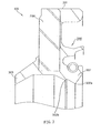
- FIG. 3 is a schematic sectional view of a reciprocating seal according to a conventional art.
- the reciprocating seal is arranged in an annular space between a shaft (not shown) and the inner periphery of a housing (in more detail, shaft hole made in the housing), which move relatively in the direction of the shaft, to form a sealed space.
- a reciprocating seal 100 according to the conventional art, as shown in the drawing, is mainly provided with a metal ring 200 and a rubber seal 300 baked on the metal ring 200.
- the rubber seal 300 has an outer peripheral seal portion 301 mounted on the inner periphery of the housing, a main seal lip 302 brought into sliding contact with the outer peripheral surface of the shaft, and a sub-seal lip 303 similarly brought into sliding contact with the outer peripheral surface of the shaft.
- the reciprocating seal constructed in this manner is required to improve frictional force characteristics.
- the main seal lip 302 has a two-step lip structure including the first lip 302a of the first step and the second lip 302b of the second step.
- both of the first lip 302a and the second lip 302b are brought into sliding contact with the surface of the shaft to stabilize the position of the main seal lip 302.
- the frictional force can be made uniform to improve frictional force characteristics.
- Structures of roughening the surface of the second lip in this manner include structures of matting the surface of the lip, forming spiral screw protrusions on the surface of the lip, and forming parallel protrusions vertical to the shaft on the surface of the lip (see the above patent publication).
- the surface of the lip is formed in random asperity.
- the amount of leak of sealed-in fluid (which is usually oil, so descriptions will be provided below, assuming that the sealed-in fluid is oil) becomes nonuniform in whole and hence there is a possibility that the amount of leak might increase in part.
- the object of the invention is to provide a reciprocating seal capable of improving frictional force characteristics and at the same time improving sealing performance.
- the invention adopts the following construction.
- a reciprocating seal that is provided in an annular space formed between a shaft and a housing, which move relatively to each other in the direction of the shaft, and has a seal lip brought into sliding contact with the surface of the shaft, wherein the seal lip has a two-step lip structure in which a plurality of protrusions extending in the direction of the shaft are formed on the surface of the lip of the second step.
- the seal lip has the two-step lip structure and hence the position of the seal lip can be stabilized.
- the plurality of protrusions are formed on the surface of the lip of the second step, they can prevent an increase in the frictional force.
- the plurality of these protrusions are so constructed as to extend in the direction of the shaft and hence the protrusions do not scrape off sealed-in fluid.
- Fig. 1 is a schematic sectional view of a reciprocating seal according to the embodiment of the invention.
- the reciprocating seal 1 according to the embodiment of the invention can be suitably used for a shock absorber mounted in an automobile and the like.
- the reciprocating seal 1 is arranged in an annular space between a shaft (not shown) and the inner periphery of a housing (shaft hole made in the housing, in more detail), which move relatively to each other in the direction of the shaft, to form a sealed space.
- oil of sealed-in fluid is hermetically sealed in a hermetically sealed space formed by the reciprocating seal 1.
- the reciprocating seal 1 according to this embodiment is roughly provided with a metal ring 2 and a rubber seal 3 baked on the metal ring 2.
- the rubber seal 3 has an outer peripheral seal portion 31 mounted on the inner periphery of a housing not shown (the inner periphery of a shaft hole made in the housing), a main seal lip 32 brought into sliding contact with the outer peripheral surface of a shaft (not shown), and a sub-seal lip 33 similarly brought into sliding contact with the outer peripheral surface of the shaft.
- a spring 4 for pressing the lip onto the surface of the shaft is provided on the outer periphery side of the main seal lip 32.
- the main seal lip 32 has a two-step lip structure. That is, the main seal lip 32 has the first lip 32a of the first step located near the sealed-in fluid side and the second lip 32b of the second step located opposite to the sealed-in fluid side.
- the two-step lip structure is adopted and both of the first lip 32a and the second lip 32b are brought into sliding contact with the surface of the shaft to stabilize the position of the main seal lip 32.
- the distribution of frictional force can be made uniform to improve frictional force characteristics. That is, fine vibrations caused when the main seal lip 32 is brought into sliding contact with the surface of the shaft can be reduced.
- a plurality of protrusions 34 extending in the direction of the shaft are formed on the sliding contact surface (surface of the lip opposite to the sealed-in fluid side in this embodiment) of the second lip 32b.
- These protrusions 34 are formed at equal intervals along the entire periphery.
- Fig. 2 is a sectional view showing conceptually protrusions formed on the reciprocating seal according to embodiment of the invention.
- the sectional shape of the protrusion is made triangular.
- the height h of the protrusion is made 2 to 500 ⁇ m and, when taking elastic contact into consideration, 5 to 100 ⁇ m.
- the interval w of the protrusions is 0.005 to 1.0 mm and, when taking elastic contact into consideration, 0.01 to 0.2 mm.
- the vertical angle of the protrusion is 60 to 120°.
- a more specific example of the protrusion has a height H of 0.03 mm, an interval w of 0.15 mm, a vertical angle of 90°, and a length of 1.2 mm.
- the plurality of protrusions 34 are formed on the sliding contact surface of the second lip 32b and hence can prevent an increase in frictional force.
- This embodiment is so constructed as to prevent an increase in frictional force by the protrusions 34, so that it is possible to prevent the surface of the lip from being formed in random asperity as is the case of matting the surface of the lip.
- the plurality of protrusions 34 are so constructed as to extent in the direction of the shaft.
- the direction in which the protrusions 34 extend agrees with the direction in which the shaft and the housing move relatively to each other, and the direction in which the main seal lip 32 moves (slides to contact) with respect to the surface of the shaft.
- the velocity-ratio leak test is a test of measuring the amount of leak when a shaft is pushed or pulled in such a way that a pushing speed is different from a pulling speed.
- the oil film becomes thicker in a pulling-out step (taking-out step) and becomes thinner in a pushing step.
- the pulling-out speed in the pulling-out step was four times the pushing speed in the pushing step.
Landscapes
- Engineering & Computer Science (AREA)
- General Engineering & Computer Science (AREA)
- Mechanical Engineering (AREA)
- Sealing With Elastic Sealing Lips (AREA)
- Sealing Devices (AREA)
- Fluid-Damping Devices (AREA)
Abstract
Description
Claims (1)
- A reciprocating seal that is provided in an annular space formed between a shaft and a housing, which move relatively to each other in a direction of the shaft, and has a seal lip brought into sliding contact with a surface of the shaft,
wherein the seal lip has a two-step lip structure in which a plurality of protrusions extending in the direction of the shaft are formed on a surface of the lip of a second step.
Applications Claiming Priority (3)
| Application Number | Priority Date | Filing Date | Title |
|---|---|---|---|
| JP2002300650A JP2004138091A (en) | 2002-10-15 | 2002-10-15 | Reciprocating seal |
| JP2002300650 | 2002-10-15 | ||
| PCT/JP2003/011995 WO2004036095A1 (en) | 2002-10-15 | 2003-09-19 | Reciprocating seal |
Publications (3)
| Publication Number | Publication Date |
|---|---|
| EP1553335A1 true EP1553335A1 (en) | 2005-07-13 |
| EP1553335A4 EP1553335A4 (en) | 2010-07-14 |
| EP1553335B1 EP1553335B1 (en) | 2012-02-08 |
Family
ID=32104990
Family Applications (1)
| Application Number | Title | Priority Date | Filing Date |
|---|---|---|---|
| EP03808888A Expired - Lifetime EP1553335B1 (en) | 2002-10-15 | 2003-09-19 | Reciprocating seal |
Country Status (7)
| Country | Link |
|---|---|
| US (2) | US20060138729A1 (en) |
| EP (1) | EP1553335B1 (en) |
| JP (1) | JP2004138091A (en) |
| KR (1) | KR20050071545A (en) |
| CN (1) | CN100390445C (en) |
| AU (1) | AU2003264524A1 (en) |
| WO (1) | WO2004036095A1 (en) |
Families Citing this family (22)
| Publication number | Priority date | Publication date | Assignee | Title |
|---|---|---|---|---|
| JP2006242373A (en) * | 2004-09-24 | 2006-09-14 | Nok Corp | Sealing device |
| JP2008101640A (en) * | 2006-10-17 | 2008-05-01 | Nok Corp | Sealing device for reciprocating shaft |
| US7887062B2 (en) * | 2007-04-18 | 2011-02-15 | Freudenberg-Nok General Partnership | Radial shaft seal with large radial offset accommodation |
| US7963526B2 (en) * | 2007-05-15 | 2011-06-21 | Freudenberg-Nok General Partnership | Prelubricated multi-lipped radial shaft seal with large radial offset accommodation |
| DE102007036625B4 (en) * | 2007-08-02 | 2013-10-17 | Ab Skf | sealing element |
| JP2009058051A (en) * | 2007-08-31 | 2009-03-19 | Nok Corp | Sealing device for reciprocating shaft |
| JP2010038328A (en) * | 2008-08-07 | 2010-02-18 | Nok Corp | Sealing device |
| JP5475866B2 (en) * | 2010-03-08 | 2014-04-16 | 本田技研工業株式会社 | Automotive engine oil seal |
| EP2546558A4 (en) * | 2010-03-08 | 2014-04-02 | Honda Motor Co Ltd | Vehicle valve stem seal |
| JP5475867B2 (en) * | 2010-03-08 | 2014-04-16 | 本田技研工業株式会社 | Automotive transmission oil seal |
| CN101975278B (en) * | 2010-11-04 | 2012-12-26 | 重庆大学 | Self-healing seal device based on magnetorheological rubber and magnetorheological grease and reciprocating mechanism |
| DE102011002491A1 (en) * | 2011-01-11 | 2012-07-12 | Aktiebolaget Skf | Radial shaft seal |
| US20150014941A1 (en) * | 2012-01-23 | 2015-01-15 | Daikin Industries, Ltd. | Oil seal for automobile |
| JP5950997B2 (en) * | 2012-02-15 | 2016-07-13 | イーグル工業株式会社 | Shaft seal device |
| JP5880685B2 (en) * | 2012-03-13 | 2016-03-09 | ダイキン工業株式会社 | Automotive filler cap |
| DE102013207029B4 (en) * | 2013-04-18 | 2016-05-04 | Aktiebolaget Skf | Radial shaft seal arrangement |
| CN103742651B (en) * | 2014-01-29 | 2016-11-16 | 烟台润蚨祥油封有限公司 | A kind of low friction reciprocating movement sealing part |
| WO2014183542A1 (en) * | 2013-05-16 | 2014-11-20 | 烟台润蚨祥油封有限公司 | Reciprocating motion seal component |
| CN105020323A (en) * | 2014-04-26 | 2015-11-04 | 烟台润蚨祥油封有限公司 | Dust sealing structure assembly |
| CN105276066A (en) * | 2014-06-24 | 2016-01-27 | 烟台润蚨祥油封有限公司 | Damper sealing system |
| CN105782447B (en) * | 2014-12-25 | 2019-06-14 | 斯凯孚公司 | shaft seal |
| ES2841800T3 (en) * | 2016-10-20 | 2021-07-09 | Henn Gmbh & Co Kg | Plug coupling seal for a fluid passage of a drive motor |
Family Cites Families (19)
| Publication number | Priority date | Publication date | Assignee | Title |
|---|---|---|---|---|
| GB1219272A (en) * | 1967-05-30 | 1971-01-13 | Dunlop Co Ltd | Improvements in sealing rings |
| JPS63168365A (en) | 1986-12-29 | 1988-07-12 | Nec Corp | Character pattern access system for printer |
| JPS63168365U (en) * | 1987-04-22 | 1988-11-02 | ||
| JPS6427410A (en) | 1988-04-04 | 1989-01-30 | Mitsubishi Agricult Mach | Reaper in harvester |
| JP2725292B2 (en) * | 1988-07-22 | 1998-03-11 | 株式会社阪上製作所 | Backup ring |
| DE3830706A1 (en) * | 1988-09-09 | 1990-03-22 | Freudenberg Carl Fa | SHAFT SEAL |
| JPH02121668A (en) | 1988-11-01 | 1990-05-09 | Tokyo Electric Co Ltd | bath pump |
| JPH02136858A (en) | 1988-11-18 | 1990-05-25 | Canon Inc | Photosensitive resin composition |
| US4962359A (en) | 1989-06-29 | 1990-10-09 | Hewlett-Packard Company | Dual directional bridge and balun used as reflectometer test set |
| JP3152466B2 (en) | 1991-04-04 | 2001-04-03 | 三菱電機株式会社 | Sorting device and sorting method |
| GB9112949D0 (en) | 1991-06-15 | 1991-08-07 | Gen Motors France | Master cylinder and end fitting therefor |
| JPH0684067A (en) * | 1992-09-04 | 1994-03-25 | Murata Mfg Co Ltd | Cup vender dispensing nozzle |
| JPH0684067U (en) * | 1993-05-19 | 1994-12-02 | 株式会社荒井製作所 | Reciprocating oil seal |
| JP3261275B2 (en) * | 1994-12-28 | 2002-02-25 | エヌオーケー株式会社 | Sealing device |
| US6029980A (en) * | 1997-09-18 | 2000-02-29 | Freudenberg-Nok General Partnership | Fluid side contamination exclusion sealing lip for radial shaft seals |
| US6279914B1 (en) * | 1997-10-24 | 2001-08-28 | Eagle Industry Co., Ltd. | Sealing apparatus |
| JP4244442B2 (en) * | 1998-06-12 | 2009-03-25 | Nok株式会社 | Sealing device |
| JP2001355740A (en) * | 2000-06-15 | 2001-12-26 | Nok Corp | Oil seal |
| US6729624B1 (en) * | 2001-02-20 | 2004-05-04 | Freudenberg-Nok General Partnership | Radial shaft seal |
-
2002
- 2002-10-15 JP JP2002300650A patent/JP2004138091A/en active Pending
-
2003
- 2003-09-19 EP EP03808888A patent/EP1553335B1/en not_active Expired - Lifetime
- 2003-09-19 AU AU2003264524A patent/AU2003264524A1/en not_active Abandoned
- 2003-09-19 WO PCT/JP2003/011995 patent/WO2004036095A1/en not_active Ceased
- 2003-09-19 CN CNB038241412A patent/CN100390445C/en not_active Expired - Lifetime
- 2003-09-19 KR KR1020057005880A patent/KR20050071545A/en not_active Ceased
- 2003-09-19 US US10/531,443 patent/US20060138729A1/en not_active Abandoned
-
2008
- 2008-09-03 US US12/230,708 patent/US7918463B2/en not_active Expired - Fee Related
Also Published As
| Publication number | Publication date |
|---|---|
| WO2004036095A1 (en) | 2004-04-29 |
| CN100390445C (en) | 2008-05-28 |
| KR20050071545A (en) | 2005-07-07 |
| CN1688832A (en) | 2005-10-26 |
| EP1553335B1 (en) | 2012-02-08 |
| US20090134586A1 (en) | 2009-05-28 |
| JP2004138091A (en) | 2004-05-13 |
| AU2003264524A1 (en) | 2004-05-04 |
| US7918463B2 (en) | 2011-04-05 |
| EP1553335A4 (en) | 2010-07-14 |
| US20060138729A1 (en) | 2006-06-29 |
Similar Documents
| Publication | Publication Date | Title |
|---|---|---|
| US7918463B2 (en) | Reciprocating seal | |
| KR101194430B1 (en) | Sealing device for reciprocating shaft | |
| EP1666778A1 (en) | Sealing device for reciprocating shaft | |
| US20100295253A1 (en) | Packing and sealing system | |
| JPH07158746A (en) | Rod seal or piston seal | |
| US7648144B2 (en) | Sealing device | |
| CN110520658B (en) | Configuration of seals | |
| US7797829B2 (en) | Oil ring, manufacturing method thereof, and piston structure using the oil ring | |
| JP5497137B1 (en) | Reciprocating sealing device | |
| JPH08184377A (en) | Sealing device for reciprocation | |
| JP2002013642A (en) | Sealing device | |
| JP2003294154A (en) | Reciprocation seal | |
| JP2001349438A (en) | Sealing device | |
| US20080023893A1 (en) | Hermetically Sealing Device | |
| JPS6027256Y2 (en) | Sealing device | |
| JPH0744852Y2 (en) | Packing | |
| JPH074365Y2 (en) | Reciprocating oil seal | |
| JP2003074710A (en) | Sealing device | |
| JP2002005218A (en) | Sealing device | |
| JP2592485Y2 (en) | Reciprocating sealing device | |
| JPS6030518Y2 (en) | Sealing device | |
| JP3051664B2 (en) | Shaft sealing device for reciprocating motion | |
| JPS6235980Y2 (en) | ||
| JPH0529418Y2 (en) | ||
| JPH089490Y2 (en) | Oil seal |
Legal Events
| Date | Code | Title | Description |
|---|---|---|---|
| PUAI | Public reference made under article 153(3) epc to a published international application that has entered the european phase |
Free format text: ORIGINAL CODE: 0009012 |
|
| 17P | Request for examination filed |
Effective date: 20050331 |
|
| AK | Designated contracting states |
Kind code of ref document: A1 Designated state(s): AT BE BG CH CY CZ DE DK EE ES FI FR GB GR HU IE IT LI LU MC NL PT RO SE SI SK TR |
|
| AX | Request for extension of the european patent |
Extension state: AL LT LV MK |
|
| DAX | Request for extension of the european patent (deleted) | ||
| RBV | Designated contracting states (corrected) |
Designated state(s): DE FR GB |
|
| A4 | Supplementary search report drawn up and despatched |
Effective date: 20100610 |
|
| 17Q | First examination report despatched |
Effective date: 20100930 |
|
| GRAP | Despatch of communication of intention to grant a patent |
Free format text: ORIGINAL CODE: EPIDOSNIGR1 |
|
| RIC1 | Information provided on ipc code assigned before grant |
Ipc: F16J 15/32 20060101AFI20110725BHEP |
|
| GRAS | Grant fee paid |
Free format text: ORIGINAL CODE: EPIDOSNIGR3 |
|
| GRAA | (expected) grant |
Free format text: ORIGINAL CODE: 0009210 |
|
| AK | Designated contracting states |
Kind code of ref document: B1 Designated state(s): DE FR GB |
|
| REG | Reference to a national code |
Ref country code: GB Ref legal event code: FG4D |
|
| REG | Reference to a national code |
Ref country code: DE Ref legal event code: R096 Ref document number: 60339976 Country of ref document: DE Effective date: 20120405 |
|
| PLBE | No opposition filed within time limit |
Free format text: ORIGINAL CODE: 0009261 |
|
| STAA | Information on the status of an ep patent application or granted ep patent |
Free format text: STATUS: NO OPPOSITION FILED WITHIN TIME LIMIT |
|
| 26N | No opposition filed |
Effective date: 20121109 |
|
| REG | Reference to a national code |
Ref country code: DE Ref legal event code: R097 Ref document number: 60339976 Country of ref document: DE Effective date: 20121109 |
|
| REG | Reference to a national code |
Ref country code: FR Ref legal event code: PLFP Year of fee payment: 14 |
|
| REG | Reference to a national code |
Ref country code: FR Ref legal event code: PLFP Year of fee payment: 15 |
|
| REG | Reference to a national code |
Ref country code: FR Ref legal event code: PLFP Year of fee payment: 16 |
|
| PGFP | Annual fee paid to national office [announced via postgrant information from national office to epo] |
Ref country code: GB Payment date: 20220728 Year of fee payment: 20 Ref country code: DE Payment date: 20220621 Year of fee payment: 20 |
|
| PGFP | Annual fee paid to national office [announced via postgrant information from national office to epo] |
Ref country code: FR Payment date: 20220808 Year of fee payment: 20 |
|
| REG | Reference to a national code |
Ref country code: DE Ref legal event code: R071 Ref document number: 60339976 Country of ref document: DE |
|
| REG | Reference to a national code |
Ref country code: GB Ref legal event code: PE20 Expiry date: 20230918 |
|
| PG25 | Lapsed in a contracting state [announced via postgrant information from national office to epo] |
Ref country code: GB Free format text: LAPSE BECAUSE OF EXPIRATION OF PROTECTION Effective date: 20230918 |