EP1553312A2 - Procédé pour créer une liasion électroconductrice entre une unité de connexion électrique et une piece en tôle, élément de fixation et composant assemblé correspondants. - Google Patents
Procédé pour créer une liasion électroconductrice entre une unité de connexion électrique et une piece en tôle, élément de fixation et composant assemblé correspondants. Download PDFInfo
- Publication number
- EP1553312A2 EP1553312A2 EP20050007118 EP05007118A EP1553312A2 EP 1553312 A2 EP1553312 A2 EP 1553312A2 EP 20050007118 EP20050007118 EP 20050007118 EP 05007118 A EP05007118 A EP 05007118A EP 1553312 A2 EP1553312 A2 EP 1553312A2
- Authority
- EP
- European Patent Office
- Prior art keywords
- fastening element
- sheet metal
- metal part
- rotation
- rivet
- Prior art date
- Legal status (The legal status is an assumption and is not a legal conclusion. Google has not performed a legal analysis and makes no representation as to the accuracy of the status listed.)
- Withdrawn
Links
- 229910052751 metal Inorganic materials 0.000 title claims abstract description 75
- 239000002184 metal Substances 0.000 title claims abstract description 75
- 238000000034 method Methods 0.000 title claims abstract description 16
- 238000005520 cutting process Methods 0.000 claims description 12
- 238000004080 punching Methods 0.000 claims description 8
- 238000004519 manufacturing process Methods 0.000 claims description 4
- 239000011253 protective coating Substances 0.000 claims description 3
- 230000007704 transition Effects 0.000 claims description 3
- 239000004922 lacquer Substances 0.000 claims 1
- 239000003973 paint Substances 0.000 claims 1
- 210000003128 head Anatomy 0.000 description 19
- 239000000463 material Substances 0.000 description 10
- 210000001331 nose Anatomy 0.000 description 4
- 230000002349 favourable effect Effects 0.000 description 3
- 229910045601 alloy Inorganic materials 0.000 description 2
- 239000000956 alloy Substances 0.000 description 2
- 238000002360 preparation method Methods 0.000 description 2
- 239000011241 protective layer Substances 0.000 description 2
- 229910000838 Al alloy Inorganic materials 0.000 description 1
- OKTJSMMVPCPJKN-UHFFFAOYSA-N Carbon Chemical compound [C] OKTJSMMVPCPJKN-UHFFFAOYSA-N 0.000 description 1
- 229910000975 Carbon steel Inorganic materials 0.000 description 1
- 101001108245 Cavia porcellus Neuronal pentraxin-2 Proteins 0.000 description 1
- 229910000861 Mg alloy Inorganic materials 0.000 description 1
- 229910000831 Steel Inorganic materials 0.000 description 1
- 239000000853 adhesive Substances 0.000 description 1
- 230000001070 adhesive effect Effects 0.000 description 1
- 229910052782 aluminium Inorganic materials 0.000 description 1
- XAGFODPZIPBFFR-UHFFFAOYSA-N aluminium Chemical compound [Al] XAGFODPZIPBFFR-UHFFFAOYSA-N 0.000 description 1
- 239000002519 antifouling agent Substances 0.000 description 1
- 230000015572 biosynthetic process Effects 0.000 description 1
- 229910052799 carbon Inorganic materials 0.000 description 1
- 238000005260 corrosion Methods 0.000 description 1
- 230000007797 corrosion Effects 0.000 description 1
- 238000002788 crimping Methods 0.000 description 1
- 230000005484 gravity Effects 0.000 description 1
- 239000010410 layer Substances 0.000 description 1
- 239000007769 metal material Substances 0.000 description 1
- 238000003825 pressing Methods 0.000 description 1
- 239000007787 solid Substances 0.000 description 1
- 125000006850 spacer group Chemical group 0.000 description 1
- 239000010959 steel Substances 0.000 description 1
- XLYOFNOQVPJJNP-UHFFFAOYSA-N water Substances O XLYOFNOQVPJJNP-UHFFFAOYSA-N 0.000 description 1
Images


Classifications
-
- F—MECHANICAL ENGINEERING; LIGHTING; HEATING; WEAPONS; BLASTING
- F16—ENGINEERING ELEMENTS AND UNITS; GENERAL MEASURES FOR PRODUCING AND MAINTAINING EFFECTIVE FUNCTIONING OF MACHINES OR INSTALLATIONS; THERMAL INSULATION IN GENERAL
- F16B—DEVICES FOR FASTENING OR SECURING CONSTRUCTIONAL ELEMENTS OR MACHINE PARTS TOGETHER, e.g. NAILS, BOLTS, CIRCLIPS, CLAMPS, CLIPS OR WEDGES; JOINTS OR JOINTING
- F16B37/00—Nuts or like thread-engaging members
- F16B37/005—Nuts or like thread-engaging members into which threads are cut during screwing
-
- B—PERFORMING OPERATIONS; TRANSPORTING
- B23—MACHINE TOOLS; METAL-WORKING NOT OTHERWISE PROVIDED FOR
- B23P—METAL-WORKING NOT OTHERWISE PROVIDED FOR; COMBINED OPERATIONS; UNIVERSAL MACHINE TOOLS
- B23P19/00—Machines for simply fitting together or separating metal parts or objects, or metal and non-metal parts, whether or not involving some deformation; Tools or devices therefor so far as not provided for in other classes
- B23P19/04—Machines for simply fitting together or separating metal parts or objects, or metal and non-metal parts, whether or not involving some deformation; Tools or devices therefor so far as not provided for in other classes for assembling or disassembling parts
- B23P19/06—Screw or nut setting or loosening machines
- B23P19/062—Pierce nut setting machines
-
- F—MECHANICAL ENGINEERING; LIGHTING; HEATING; WEAPONS; BLASTING
- F16—ENGINEERING ELEMENTS AND UNITS; GENERAL MEASURES FOR PRODUCING AND MAINTAINING EFFECTIVE FUNCTIONING OF MACHINES OR INSTALLATIONS; THERMAL INSULATION IN GENERAL
- F16B—DEVICES FOR FASTENING OR SECURING CONSTRUCTIONAL ELEMENTS OR MACHINE PARTS TOGETHER, e.g. NAILS, BOLTS, CIRCLIPS, CLAMPS, CLIPS OR WEDGES; JOINTS OR JOINTING
- F16B37/00—Nuts or like thread-engaging members
- F16B37/04—Devices for fastening nuts to surfaces, e.g. sheets, plates
- F16B37/06—Devices for fastening nuts to surfaces, e.g. sheets, plates by means of welding or riveting
- F16B37/062—Devices for fastening nuts to surfaces, e.g. sheets, plates by means of welding or riveting by means of riveting
- F16B37/065—Devices for fastening nuts to surfaces, e.g. sheets, plates by means of welding or riveting by means of riveting by deforming the material of the nut
-
- H—ELECTRICITY
- H01—ELECTRIC ELEMENTS
- H01R—ELECTRICALLY-CONDUCTIVE CONNECTIONS; STRUCTURAL ASSOCIATIONS OF A PLURALITY OF MUTUALLY-INSULATED ELECTRICAL CONNECTING ELEMENTS; COUPLING DEVICES; CURRENT COLLECTORS
- H01R9/00—Structural associations of a plurality of mutually-insulated electrical connecting elements, e.g. terminal strips or terminal blocks; Terminals or binding posts mounted upon a base or in a case; Bases therefor
- H01R9/16—Fastening of connecting parts to base or case; Insulating connecting parts from base or case
- H01R9/18—Fastening by means of screw or nut
-
- H—ELECTRICITY
- H01—ELECTRIC ELEMENTS
- H01R—ELECTRICALLY-CONDUCTIVE CONNECTIONS; STRUCTURAL ASSOCIATIONS OF A PLURALITY OF MUTUALLY-INSULATED ELECTRICAL CONNECTING ELEMENTS; COUPLING DEVICES; CURRENT COLLECTORS
- H01R13/00—Details of coupling devices of the kinds covered by groups H01R12/70 or H01R24/00 - H01R33/00
- H01R13/73—Means for mounting coupling parts to apparatus or structures, e.g. to a wall
- H01R13/74—Means for mounting coupling parts in openings of a panel
-
- H—ELECTRICITY
- H01—ELECTRIC ELEMENTS
- H01R—ELECTRICALLY-CONDUCTIVE CONNECTIONS; STRUCTURAL ASSOCIATIONS OF A PLURALITY OF MUTUALLY-INSULATED ELECTRICAL CONNECTING ELEMENTS; COUPLING DEVICES; CURRENT COLLECTORS
- H01R4/00—Electrically-conductive connections between two or more conductive members in direct contact, i.e. touching one another; Means for effecting or maintaining such contact; Electrically-conductive connections having two or more spaced connecting locations for conductors and using contact members penetrating insulation
- H01R4/58—Electrically-conductive connections between two or more conductive members in direct contact, i.e. touching one another; Means for effecting or maintaining such contact; Electrically-conductive connections having two or more spaced connecting locations for conductors and using contact members penetrating insulation characterised by the form or material of the contacting members
- H01R4/64—Connections between or with conductive parts having primarily a non-electric function, e.g. frame, casing, rail
-
- Y—GENERAL TAGGING OF NEW TECHNOLOGICAL DEVELOPMENTS; GENERAL TAGGING OF CROSS-SECTIONAL TECHNOLOGIES SPANNING OVER SEVERAL SECTIONS OF THE IPC; TECHNICAL SUBJECTS COVERED BY FORMER USPC CROSS-REFERENCE ART COLLECTIONS [XRACs] AND DIGESTS
- Y10—TECHNICAL SUBJECTS COVERED BY FORMER USPC
- Y10T—TECHNICAL SUBJECTS COVERED BY FORMER US CLASSIFICATION
- Y10T29/00—Metal working
- Y10T29/49—Method of mechanical manufacture
- Y10T29/49826—Assembling or joining
- Y10T29/49833—Punching, piercing or reaming part by surface of second part
- Y10T29/49835—Punching, piercing or reaming part by surface of second part with shaping
- Y10T29/49837—Punching, piercing or reaming part by surface of second part with shaping of first part
-
- Y—GENERAL TAGGING OF NEW TECHNOLOGICAL DEVELOPMENTS; GENERAL TAGGING OF CROSS-SECTIONAL TECHNOLOGIES SPANNING OVER SEVERAL SECTIONS OF THE IPC; TECHNICAL SUBJECTS COVERED BY FORMER USPC CROSS-REFERENCE ART COLLECTIONS [XRACs] AND DIGESTS
- Y10—TECHNICAL SUBJECTS COVERED BY FORMER USPC
- Y10T—TECHNICAL SUBJECTS COVERED BY FORMER US CLASSIFICATION
- Y10T29/00—Metal working
- Y10T29/49—Method of mechanical manufacture
- Y10T29/49826—Assembling or joining
- Y10T29/49908—Joining by deforming
- Y10T29/49915—Overedge assembling of seated part
- Y10T29/4992—Overedge assembling of seated part by flaring inserted cup or tube end
-
- Y—GENERAL TAGGING OF NEW TECHNOLOGICAL DEVELOPMENTS; GENERAL TAGGING OF CROSS-SECTIONAL TECHNOLOGIES SPANNING OVER SEVERAL SECTIONS OF THE IPC; TECHNICAL SUBJECTS COVERED BY FORMER USPC CROSS-REFERENCE ART COLLECTIONS [XRACs] AND DIGESTS
- Y10—TECHNICAL SUBJECTS COVERED BY FORMER USPC
- Y10T—TECHNICAL SUBJECTS COVERED BY FORMER US CLASSIFICATION
- Y10T29/00—Metal working
- Y10T29/49—Method of mechanical manufacture
- Y10T29/49826—Assembling or joining
- Y10T29/49908—Joining by deforming
- Y10T29/49938—Radially expanding part in cavity, aperture, or hollow body
- Y10T29/49943—Riveting
-
- Y—GENERAL TAGGING OF NEW TECHNOLOGICAL DEVELOPMENTS; GENERAL TAGGING OF CROSS-SECTIONAL TECHNOLOGIES SPANNING OVER SEVERAL SECTIONS OF THE IPC; TECHNICAL SUBJECTS COVERED BY FORMER USPC CROSS-REFERENCE ART COLLECTIONS [XRACs] AND DIGESTS
- Y10—TECHNICAL SUBJECTS COVERED BY FORMER USPC
- Y10T—TECHNICAL SUBJECTS COVERED BY FORMER US CLASSIFICATION
- Y10T29/00—Metal working
- Y10T29/49—Method of mechanical manufacture
- Y10T29/49826—Assembling or joining
- Y10T29/49947—Assembling or joining by applying separate fastener
- Y10T29/49948—Multipart cooperating fastener [e.g., bolt and nut]
-
- Y—GENERAL TAGGING OF NEW TECHNOLOGICAL DEVELOPMENTS; GENERAL TAGGING OF CROSS-SECTIONAL TECHNOLOGIES SPANNING OVER SEVERAL SECTIONS OF THE IPC; TECHNICAL SUBJECTS COVERED BY FORMER USPC CROSS-REFERENCE ART COLLECTIONS [XRACs] AND DIGESTS
- Y10—TECHNICAL SUBJECTS COVERED BY FORMER USPC
- Y10T—TECHNICAL SUBJECTS COVERED BY FORMER US CLASSIFICATION
- Y10T29/00—Metal working
- Y10T29/49—Method of mechanical manufacture
- Y10T29/49826—Assembling or joining
- Y10T29/49947—Assembling or joining by applying separate fastener
- Y10T29/49954—Fastener deformed after application
- Y10T29/49956—Riveting
-
- Y—GENERAL TAGGING OF NEW TECHNOLOGICAL DEVELOPMENTS; GENERAL TAGGING OF CROSS-SECTIONAL TECHNOLOGIES SPANNING OVER SEVERAL SECTIONS OF THE IPC; TECHNICAL SUBJECTS COVERED BY FORMER USPC CROSS-REFERENCE ART COLLECTIONS [XRACs] AND DIGESTS
- Y10—TECHNICAL SUBJECTS COVERED BY FORMER USPC
- Y10T—TECHNICAL SUBJECTS COVERED BY FORMER US CLASSIFICATION
- Y10T29/00—Metal working
- Y10T29/53—Means to assemble or disassemble
- Y10T29/5343—Means to drive self-piercing work part
-
- Y—GENERAL TAGGING OF NEW TECHNOLOGICAL DEVELOPMENTS; GENERAL TAGGING OF CROSS-SECTIONAL TECHNOLOGIES SPANNING OVER SEVERAL SECTIONS OF THE IPC; TECHNICAL SUBJECTS COVERED BY FORMER USPC CROSS-REFERENCE ART COLLECTIONS [XRACs] AND DIGESTS
- Y10—TECHNICAL SUBJECTS COVERED BY FORMER USPC
- Y10T—TECHNICAL SUBJECTS COVERED BY FORMER US CLASSIFICATION
- Y10T403/00—Joints and connections
- Y10T403/49—Member deformed in situ
- Y10T403/4966—Deformation occurs simultaneously with assembly
-
- Y—GENERAL TAGGING OF NEW TECHNOLOGICAL DEVELOPMENTS; GENERAL TAGGING OF CROSS-SECTIONAL TECHNOLOGIES SPANNING OVER SEVERAL SECTIONS OF THE IPC; TECHNICAL SUBJECTS COVERED BY FORMER USPC CROSS-REFERENCE ART COLLECTIONS [XRACs] AND DIGESTS
- Y10—TECHNICAL SUBJECTS COVERED BY FORMER USPC
- Y10T—TECHNICAL SUBJECTS COVERED BY FORMER US CLASSIFICATION
- Y10T403/00—Joints and connections
- Y10T403/49—Member deformed in situ
- Y10T403/4974—Member deformed in situ by piercing
-
- Y—GENERAL TAGGING OF NEW TECHNOLOGICAL DEVELOPMENTS; GENERAL TAGGING OF CROSS-SECTIONAL TECHNOLOGIES SPANNING OVER SEVERAL SECTIONS OF THE IPC; TECHNICAL SUBJECTS COVERED BY FORMER USPC CROSS-REFERENCE ART COLLECTIONS [XRACs] AND DIGESTS
- Y10—TECHNICAL SUBJECTS COVERED BY FORMER USPC
- Y10T—TECHNICAL SUBJECTS COVERED BY FORMER US CLASSIFICATION
- Y10T403/00—Joints and connections
- Y10T403/49—Member deformed in situ
- Y10T403/4991—Both members deformed
Definitions
- the present invention relates to a functional element with a annular bearing surface having head portion and a tubular provided on the side of the support surface of the head part, from the headboard away extending rivet section. Furthermore, the invention relates to a Assembly part consisting of a sheet metal part and such Functional element and a method for attachment of such Functional element to a sheet metal part.
- a functional element of the type mentioned is, for example EP-A-539743, both in the form of a nut member as well as in the form of a bolt element.
- the sheet preparation includes in EP-A-539793 the production of an axially projecting annular lip in the sheet metal part defining an opening into which the rivet portion of the Function element must be brought into it. In this operation is the annular lip on the side of the sheet metal part from which the functional element is introduced.
- the protruding lip with the prefabricated Opening means in practice that the functional element with high Accuracy with respect to the sheet metal part must be aligned to the ensure proper attachment of the functional element.
- Object of the present invention is to provide a functional element and a Provide method for attaching the functional element to a sheet metal part, the cost-effective attachment of the functional element a sheet metal part allows, without any special demands on the orientation of the functional element with the component, the requirements in case of any necessary preparation of the sheet metal part are not very high and yet a quality connection between the functional element and the sheet metal part comes about. Furthermore, a self-piercing execution of the element, if desired, be possible and it should also connect between the functional element and the sheet metal part come about, which also in coated sheets an electrically conductive connection allows.
- a functional element according to the invention of the type mentioned above which is characterized in that a tubular guide section is concentric with the tubular one Rivet and radially disposed within this, with between the guide portion (18) and the rivet portion provided an annular gap is and the guide section over the free end of the rivet section protrudes. Furthermore, according to the invention an assembly component according to claim 20 and a method for attaching a Functional element according to the independent claims 24 and 25 intended.
- this pre-perforation can also be made be that on the side of the sheet, from which the functional element is introduced, no protruding annular lip is present, which also the Alignment of the functional element with the sheet metal part easier.
- the guide section formed of the functional element as a punching section can be, whereby the functional element self-piercing in the Sheet metal part can be introduced so that a pre-punching at all is not necessary and the demands on the orientation of the functional element be even lower with the sheet metal part.
- Self-education of the functional element is also a low-priced Manufacture of the assembly part achieved since the operation of Pre-perforation of the sheet metal part is eliminated. As a result, the method for Attachment of the functional element to the sheet metal part simplified.
- DE-C-3446978 describes inter alia Nut element which is introduced into a sheet-metal part by self-stamping
- DE-C-3447006 discloses a similarly designed bolt element.
- Neither the nut member nor the bolt member according to the above German patents mentioned has a leadership section in addition to the rivet section, so that the rivet section both the punching function as also has to perform the riveting function, which is more complicated and ultimately stricter requirements for the rivet section and the used Template sets, as is the case with the present invention.
- the free end of the wall of the annular Rivet section seen in an axial sectional plane, both rounded on the radially outer side as well as on the radially inner side is and, for example, a semi-circular or arrowhead-like shape having.
- the guide section of the functional element leads when attaching the functional element to a sheet metal part to a cone-shaped depression in the sheet metal part, namely in a pre-punched Sheet metal part in the expansion of the hole through the guide section and in a self-piercing embodiment of the functional element before cutting out a punch through the punched section trained guide section, wherein the cone-shaped recess then widened by the rivet section.
- the rounded training of outer wall of the rivet section is in the region of its free end a favorable shape for the further expansion of the hole and the corresponding Deformation of the cone-shaped wall of the depression.
- the Rounded shape on the inner side of the free end of the rivet section helps with the flanging of the rivet section, what in one correspondingly concavely curved annular surface of the die takes place.
- This form also allows the annular gap to be kept as small as possible, without affecting the process of flanging the rivet section.
- the fact that the annular gap can be kept as small as possible and even 0 mm (which means that the inner wall the rivet portion on the outer periphery of the guide portion is applied), the diameter of the functional element as a whole as possible kept small, thereby saving material and reducing costs can be.
- the annular gap preferably has a radial dimension in the range between 0 mm and about 3 mm.
- the annular gap is preferably at an axial distance in front of the annular Contact surface on the Nietabitessseite the annular bearing surface over.
- the guide portion is formed as a punching section, it has preferably an annular cutting edge at its contact surface facing away from the front end and this cutting edge acts with a corresponding shaped cutting edge of a central bore of a die together to get a clean punch from the sheet metal part at the To punch out attachment of the functional element on the sheet metal part.
- anti-rotation features in the range the annular bearing surface and / or at the rivet and / or at the lateral surface of the head part adjacent to the support surface are. If the anti-rotation features in the area of the lateral surface of the head part are provided, these can be replaced by a polygonal or grooved shape of the lateral surface are generated.
- the anti-rotation features in the area of the annular bearing surface and / or on the rivet section and optionally on the lateral surface can by noses or be formed by groove-shaped depressions.
- anti-rotation lugs are provided, they can exalted the contact surface and the rivet section in the area of the transition from the bearing surface in the rivet section are present.
- the functional element may be present as a hollow element, for example with a cylindrical receptacle for a rotatably mounted shaft or for a thread-cutting or thread-forming screw or as Snap-in receptacle for the pin of a clip or other object.
- the functional element can be designed as a nut element be, i. the functional element has a threaded cylinder, the either in the head part or in the guide section or at least partially may be provided in the head part and in the guide section.
- the functional element but can also on the outside of the guide section have a cylindrical bearing surface and it can also be realized as a bolt element.
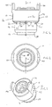
- FIG. 1 to 4 is the functional element shown there 10 with a an annular support surface 12 having headboard 14 and a tubular on the side of the support surface 12 of the Head portion 14 provided extending away from the head part 14 rivet section 16 provided.
- the functional element has a central longitudinal axis 11 on.
- a tubular guide portion 18 is concentric with the tubular Rivet section 16 and disposed radially within this, wherein between the guide portion 18 and the rivet portion 16 an annular gap 20 is provided, which is visible only in Fig. 4.
- the free end 22 of the wall of the annular rivet section 16 in the axial sectional plane of FIG. 4 seen both on the radially outer side 24 and on the radial rounded on the inner side 26 and has a rounded arrowhead here Shape.
- the tip of the arrowhead-like shape could also be rounded which would result in a semi-circular shape, but which not shown.
- the annular gap has a radial dimension from 0 mm, i. the rivet section rests against the guide section 18, but is only connected to the guide section 18 where the annular gap 20 at a short axial distance "a" in front of the annular bearing surface 12 comes to an end.
- the functional element of Figures 1 to 4 is usually by a Cold impact method produced, the basic features of which are well known are.
- the rivet section lying close to the guide section It may be necessary, the rivet section only with a certain radial distance from the guide section to produce by cold hammering and subsequently in another phase of the cold-striking process to press the rivet section to the guide section or the To widen guide section to the rivet section up to the plant or the reduction of the radial distance by a combination of the to achieve both measures. It is favorable if the annular gap 20 has the smallest possible radial width, as this leads to a compact Training the functional element leads and saves material.
- the guide portion 18 is formed here as a punching section and has an annular cutting edge 28 at its support surface 12th facing away from the end, i. at its free end.
- FIGS. 1 to 4 furthermore show anti-rotation features 30 in FIG Area of the annular bearing surface 12 and the rivet 16 on wherein the anti-rotation features are formed by lugs, the raised on the support surface 12 and the rivet 16 in the region of Transition from the support surface in the rivet 16 are present.
- the Anti-rotation lugs shown here are with side edges 30 and 32nd provided in the longitudinal direction of the element extending planes lie.
- the formed in Fig. 1 and 4 at 34 and 36 sharp-edged Anti-rotation lugs can instead be here with rounded edges be provided.
- the anti-rotation noses could also by depressions be realized in the support surface or in the rivet section.
- the possibility of the lateral surface 36 of the head part 14 would be a to give polygonal or grooved shape.
- the functional element is here realized as a nut member and has a threaded cylinder 38, the is arranged coaxially to the longitudinal axis 11 of the functional element and in This example is partially present in the guide section 18.
- Another Particularity of the nut member of Figures 1 to 4 is in the two Lobe 40 can be seen from the upper end face of the element 10th protrude and are generated by the fact that the cold impact method Material from the areas 42 is pushed up, so that to the Make 42 corresponding depressions arise, the denomination "upward" only in view of the illustration of FIG. 1 to is understood and how other places in this application only related is used on the figures and no spatial restriction represents the subject invention.
- the lobes 40 ensure that a cable lug on the functional element by means of an inserted from above Screw can be attached without the lug with the screw is turned when attaching the screw, as a Co-rotation of the cable lug through the tabs 40 is prevented.
- the functional element 10 cylindrical recesses 44 and 46 above and below the threaded cylinder 38, wherein these free spaces have a diameter, which is usually dimensioned slightly larger than the outer diameter a screw which is screwed into the threaded cylinder 38 becomes.
- threaded cylinder 38 here partially in the head part 14 and partially is arranged in the guide section 18 of the functional element 10, It could also be completely in the head section or completely in the guide section to be ordered.
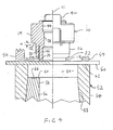
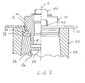
- FIG. 4 shows the functional element 10 in a first stage of FIG Attachment to a sheet metal part 50, wherein in the illustration Fig. 4, the sheet metal part. 50 is supported on a die 52 and against the die 52nd is pressed by means of an annular hold-down 54, wherein the Downholder 54 preferably, but not necessarily be provided got to.
- FIG. 4 assumes that the attachment of the Functional element 10 takes place on the sheet metal part 50 in a press, wherein the Die 52 is disposed in the lower die of the press (not shown) and the functional element 10 by means also not shown Setting head is pressed onto the sheet metal part 50, wherein the setting head on a Intermediate plate of the press or on an upper tool of the press can be appropriate.
- Such setting heads and hold-down 54 are in State of the art well known and are therefore not extra described. It should be expressed, however, that too other arrangements within a press are possible. For example If the die 52 can be arranged in an intermediate plate of the press, wherein the setting head with or without hold-down then on the upper tool the press is attached.
- the die 52 at the top Provide tool of the press and the setting head with or without hold-down then on an intermediate plate of the press or on the lower one Mount tool of the press, i. the functional element 10 in reverse direction below the sheet metal part 50 to install.
- the functional element 10 of a robot to attach to the sheet metal part 50, wherein the robot or an auxiliary robot then the die 52 holds below the sheet metal part and for attachment the required pressing force on the functional element 10 provides.
- a two-part design of the die 52 is shown. These consists of an outer ring-shaped female part 54 and an inner, also annular die part 56 with a central longitudinal bore 58, in this example, the inner female part 56 a light has conically extending outer wall, with a corresponding shaped cone-shaped inner wall 53 of the outer Matrices part 54 cooperates, so that the upper end face 60 of the inner female part 56 below the upper end face 62 of the outer Matrizenteils 54 comes to rest and thereby forms a recess 64.
- the upper end 60 of the inner female part 56 thus forms the Bottom surface of the recess 64 and otherwise has an annular concave surface 66 on.
- Both the inner female part 56 and its bore 58, and also the outer female part 54 and between the two Matrizenized recess 64, are coaxial with the central longitudinal axis 11 of the Functional element 10 is arranged.
- the template 52 could also be one-piece be executed.
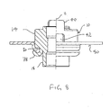
- the functional element 10 according to the present invention has the particular advantage that it also with protective layers or paint layers provided sheet metal parts 50 can be used and yet a produces excellent electrical connection, in the area of Punching holes and anti-rotation noses straight at a sharp-edged Training the anti-rotation noses the protective coating cut locally and for a metallic connection to the Sheet metal part 50 provide.
- the protective layer becomes in places damaged within the positive connection between the sheet metal part 50th and the functional element lie, so that there is a seal and corrosion is prevented.
- the positive connection between the sheet metal part and the functional element is so intense that the connection is sealed Connection that represents when it comes to a special seal arrives also by applying an adhesive to the element or the sheet metal part can be supported.
- the functional elements described here can, for example, all Materials are manufactured that have the strength class 5.6 or higher to reach.
- Such metal materials are usually carbon steels with 0.15 to 0.55% carbon content.
- the functional elements are called all materials in the frame the cold deformation the strength values of class 8 according to ISO standard reach, for example, a 35B2 alloy according to DIN 1654.
- the so formed fasteners are u.a. for all commercial Steel materials for drawable sheet metal parts as well as for aluminum or its alloys.
- functional elements come from higher strength magnesium alloys such as AM50 in question.
Applications Claiming Priority (3)
| Application Number | Priority Date | Filing Date | Title |
|---|---|---|---|
| DE10114200A DE10114200A1 (de) | 2001-03-23 | 2001-03-23 | Funktionselement, Zusammenbauteil bestehend aus einem Blechteil und einem Funktionselement sowie Verfahren zur Anbringung eines Funktionselementes an ein Blechteil |
| DE10114200 | 2001-03-23 | ||
| EP02735158A EP1370777B1 (fr) | 2001-03-23 | 2002-03-21 | Element fonctionnel, piece d'assemblage comprenant une piece de tole et un element fonctionnel, et procede permettant la fixation d'un element fonctionnel a une piece de tole |
Related Parent Applications (1)
| Application Number | Title | Priority Date | Filing Date |
|---|---|---|---|
| EP02735158A Division EP1370777B1 (fr) | 2001-03-23 | 2002-03-21 | Element fonctionnel, piece d'assemblage comprenant une piece de tole et un element fonctionnel, et procede permettant la fixation d'un element fonctionnel a une piece de tole |
Publications (2)
| Publication Number | Publication Date |
|---|---|
| EP1553312A2 true EP1553312A2 (fr) | 2005-07-13 |
| EP1553312A3 EP1553312A3 (fr) | 2006-07-26 |
Family
ID=7678667
Family Applications (2)
| Application Number | Title | Priority Date | Filing Date |
|---|---|---|---|
| EP02735158A Expired - Lifetime EP1370777B1 (fr) | 2001-03-23 | 2002-03-21 | Element fonctionnel, piece d'assemblage comprenant une piece de tole et un element fonctionnel, et procede permettant la fixation d'un element fonctionnel a une piece de tole |
| EP20050007118 Withdrawn EP1553312A3 (fr) | 2001-03-23 | 2002-03-21 | Procédé pour créer une liasion électroconductrice entre une unité de connexion électrique et une piece en tôle, élément de fixation et composant assemblé correspondants. |
Family Applications Before (1)
| Application Number | Title | Priority Date | Filing Date |
|---|---|---|---|
| EP02735158A Expired - Lifetime EP1370777B1 (fr) | 2001-03-23 | 2002-03-21 | Element fonctionnel, piece d'assemblage comprenant une piece de tole et un element fonctionnel, et procede permettant la fixation d'un element fonctionnel a une piece de tole |
Country Status (6)
| Country | Link |
|---|---|
| US (2) | US7367767B2 (fr) |
| EP (2) | EP1370777B1 (fr) |
| BR (1) | BR0208346B1 (fr) |
| DE (2) | DE10114200A1 (fr) |
| ES (1) | ES2240749T3 (fr) |
| WO (1) | WO2002077468A1 (fr) |
Cited By (2)
| Publication number | Priority date | Publication date | Assignee | Title |
|---|---|---|---|---|
| CN101994737A (zh) * | 2009-08-13 | 2011-03-30 | 形状连接技术有限公司及两合公司 | 功能元件、将功能元件引入金属片部件的方法及零件总成 |
| EP4083451A1 (fr) * | 2021-04-27 | 2022-11-02 | Profil Verbindungstechnik GmbH & Co. KG | Élément fonctionnel auto-poinçonnant, composant d'assemblage et procédé de fabrication d'un composant d'assemblage |
Families Citing this family (12)
| Publication number | Priority date | Publication date | Assignee | Title |
|---|---|---|---|---|
| DE10243759B4 (de) | 2002-09-20 | 2011-08-11 | PROFIL Verbindungstechnik GmbH & Co. KG, 61381 | Verfahren zur Erzeugung einer elektrisch leitenden Verbindung zwischen einer elektrischen Anschlusseinrichtung wie ein Kabelschuh und einem Blechteil, Befestigungselement und Zusammenbauteil |
| DE10359940B4 (de) * | 2003-12-19 | 2017-08-24 | Profil Verbindungstechnik Gmbh & Co. Kg | Verfahren zum Anbringen eines Funktionselements, Funktionselement und Zusammenbauteil |
| DE102004062391A1 (de) * | 2004-12-23 | 2006-07-13 | Profil-Verbindungstechnik Gmbh & Co. Kg | Ein durch Nieten an ein Blechteil anbringbares Element sowie Zusammenbauteil und Verfahren zur Erzeugung des Zusammenbauteils |
| RU2418206C2 (ru) * | 2006-01-05 | 2011-05-10 | Профиль-Фербиндунгстехник Гмбх Унд Ко. Кг | Крепежный элемент, узловая сборка, состоящая из крепежного элемента и детали из листового металла, а также способ закрепления крепежного элемента на детали из листового металла |
| US20070234547A1 (en) * | 2006-04-11 | 2007-10-11 | Acument Intellectual Properties, Llc | Self-piercing pin and method of installation |
| DE102006031616B4 (de) * | 2006-05-02 | 2015-05-28 | Heiko Schmidt | Verfahren zum Herstellen eines Gelenks |
| JP5148074B2 (ja) * | 2006-05-24 | 2013-02-20 | プロフィル・フェルビンドゥングステヒニック・ゲーエムベーハー・ウント・コンパニー・カーゲー | リベット締めによってシートメタル部に取り付け可能な部材と部品アッセンブリ並びにその部品アッセンブリの製造方法 |
| DE202006008721U1 (de) * | 2006-06-01 | 2007-10-11 | Profil Verbindungstechnik Gmbh & Co. Kg | Nietmutter und Kombination einer Nietmutter mit einem Blechteil |
| DE102006039699A1 (de) * | 2006-08-21 | 2008-02-28 | Arnold & Shinjo Gmbh & Co. Kg | Befestigungselement |
| US8608420B2 (en) * | 2007-08-24 | 2013-12-17 | Whitesell International Corporation | Self-attaching nut |
| DE202008017562U1 (de) * | 2008-11-18 | 2010-02-11 | Kerb-Konus-Vertriebs-Gmbh | Nietteil mit geschlitztem Schaft |
| DE102009035338A1 (de) | 2009-07-22 | 2011-01-27 | Arnold & Shinjo Gmbh & Co. Kg | Befestigen von Nietelementen |
Citations (3)
| Publication number | Priority date | Publication date | Assignee | Title |
|---|---|---|---|---|
| US1249948A (en) * | 1914-06-25 | 1917-12-11 | Hydraulic Pressed Steel Company | Process of uniting articles to sheet-metal supports. |
| CH503212A (de) * | 1969-12-02 | 1971-02-15 | Fibotema Ag | Mutter |
| DE3446978A1 (de) * | 1983-12-21 | 1985-08-14 | Profil-Verbindungstechnik Gmbh & Co Kg, 6382 Friedrichsdorf | Verfahren und vorrichtung zum befestigen eines hohlkoerperteils an einer tafel |
Family Cites Families (24)
| Publication number | Priority date | Publication date | Assignee | Title |
|---|---|---|---|---|
| US2255964A (en) * | 1937-10-04 | 1941-09-16 | Metal Fittings Inc | Bushing or ring, process of making same, and mounting therefor |
| NL283819A (fr) * | 1958-06-24 | |||
| GB991487A (en) * | 1961-10-10 | 1965-05-12 | Multifastener Corp | Nut and panel assembly and method of making same |
| US4018257A (en) * | 1975-12-15 | 1977-04-19 | Cold Fasteners, Inc. | Self-flanging nut and joint construction |
| DE3003908C2 (de) * | 1980-02-02 | 1984-10-18 | Profil-Verbindungstechnik Gmbh & Co Kg, 6382 Friedrichsdorf | Stehbolzen mit Stanz- und Nietverhalten |
| US5617652A (en) * | 1980-02-02 | 1997-04-08 | Multifastener Corporation | Fastener installation and method |
| US4911592A (en) * | 1980-02-02 | 1990-03-27 | Multifastener Corporation | Method of installation and installation apparatus |
| US5309618A (en) * | 1980-02-02 | 1994-05-10 | Profil Verbindungstechnik Gmbh & Co., Kg | Method of attaching a female fastener assembly to a panel |
| US4555838A (en) | 1983-03-28 | 1985-12-03 | Multifastener Corp. | Method of installing self-attaching fasteners |
| JPS6231712A (ja) * | 1985-07-31 | 1987-02-10 | ドイツチエ.フアスナ−.コ−ポレ−シヨン | 固着装置及びその組立体 |
| US4652169A (en) * | 1985-12-26 | 1987-03-24 | Matthews David G | Connecting structure for a hub and fan blade |
| US5006025A (en) * | 1989-12-13 | 1991-04-09 | Avibank Mfg., Inc. | Self-locking nut |
| DE69221423T2 (de) | 1991-09-30 | 1998-03-19 | Beckman Instruments Inc | Verbesserte Fluoreszenz-Erfassung von Proben in einem Kapillarrohr |
| US5251370A (en) | 1991-10-31 | 1993-10-12 | Profil Verbindungstechnik Gmbh & Co. | Method of attaching a fastening element to a panel |
| US5423645A (en) * | 1993-08-04 | 1995-06-13 | Profil Verbindungstechnik Gmbh & Co. Kg | Fastener and panel assembly |
| US5528812A (en) * | 1991-10-31 | 1996-06-25 | Profil-Verbindungstechnik Gmbh & Co. Kg | Method of attaching a fastener to a plurality of panels |
| FR2693842A1 (fr) * | 1992-07-15 | 1994-01-21 | Peugeot | Dispositif de fixation de câbles électriques. |
| DE4425839A1 (de) * | 1994-07-21 | 1996-01-25 | Bayerische Motoren Werke Ag | Gewindebolzen für Kraftfahrzeuge |
| DE19609252C1 (de) * | 1996-02-28 | 1997-01-16 | Brose Fahrzeugteile | Bauteilverbindung sowie Verfahren und Vorrichtung zu ihrer Herstellung |
| GB9809962D0 (en) * | 1998-05-08 | 1998-07-08 | Bas Components Limited | Fixing pulley wheels to plate-like structures |
| FR2792270B1 (fr) * | 1999-04-16 | 2001-07-27 | Peugeot Citroen Automobiles Sa | Prise de masse electrique pour un vehicule automobile et procede de sertissage d'un ecrou de la prise de masse |
| ES2184718T3 (es) * | 1999-07-09 | 2003-04-16 | Profil Verbindungstechnik Gmbh | Elemento funcional, metodo para fijarlo en una pieza de chapa metalica y elemento de ensamblaje. |
| JP2001289215A (ja) * | 2000-04-03 | 2001-10-19 | Aoyama Seisakusho Co Ltd | 防水グロメット |
| JP3841332B2 (ja) * | 2000-05-19 | 2006-11-01 | 株式会社青山製作所 | ピアスナット |
-
2001
- 2001-03-23 DE DE10114200A patent/DE10114200A1/de not_active Withdrawn
-
2002
- 2002-03-21 US US10/472,648 patent/US7367767B2/en not_active Expired - Fee Related
- 2002-03-21 EP EP02735158A patent/EP1370777B1/fr not_active Expired - Lifetime
- 2002-03-21 BR BRPI0208346-9A patent/BR0208346B1/pt not_active IP Right Cessation
- 2002-03-21 EP EP20050007118 patent/EP1553312A3/fr not_active Withdrawn
- 2002-03-21 DE DE50203276T patent/DE50203276D1/de not_active Expired - Lifetime
- 2002-03-21 WO PCT/EP2002/003187 patent/WO2002077468A1/fr not_active Application Discontinuation
- 2002-03-21 ES ES02735158T patent/ES2240749T3/es not_active Expired - Lifetime
-
2008
- 2008-03-26 US US12/055,914 patent/US7657987B2/en not_active Expired - Lifetime
Patent Citations (3)
| Publication number | Priority date | Publication date | Assignee | Title |
|---|---|---|---|---|
| US1249948A (en) * | 1914-06-25 | 1917-12-11 | Hydraulic Pressed Steel Company | Process of uniting articles to sheet-metal supports. |
| CH503212A (de) * | 1969-12-02 | 1971-02-15 | Fibotema Ag | Mutter |
| DE3446978A1 (de) * | 1983-12-21 | 1985-08-14 | Profil-Verbindungstechnik Gmbh & Co Kg, 6382 Friedrichsdorf | Verfahren und vorrichtung zum befestigen eines hohlkoerperteils an einer tafel |
Cited By (4)
| Publication number | Priority date | Publication date | Assignee | Title |
|---|---|---|---|---|
| CN101994737A (zh) * | 2009-08-13 | 2011-03-30 | 形状连接技术有限公司及两合公司 | 功能元件、将功能元件引入金属片部件的方法及零件总成 |
| CN101994737B (zh) * | 2009-08-13 | 2015-08-12 | 形状连接技术有限公司及两合公司 | 锚杆元件 |
| EP4083451A1 (fr) * | 2021-04-27 | 2022-11-02 | Profil Verbindungstechnik GmbH & Co. KG | Élément fonctionnel auto-poinçonnant, composant d'assemblage et procédé de fabrication d'un composant d'assemblage |
| US11971060B2 (en) | 2021-04-27 | 2024-04-30 | Profil Verbindungstechnik Gmbh & Co. Kg | Self-punching functional element, component assembly, and method of manufacturing a component assembly |
Also Published As
| Publication number | Publication date |
|---|---|
| EP1370777B1 (fr) | 2005-06-01 |
| BR0208346B1 (pt) | 2011-05-31 |
| ES2240749T3 (es) | 2005-10-16 |
| US20040148759A1 (en) | 2004-08-05 |
| DE10114200A1 (de) | 2002-09-26 |
| EP1553312A3 (fr) | 2006-07-26 |
| DE50203276D1 (de) | 2005-07-07 |
| US20080189929A1 (en) | 2008-08-14 |
| WO2002077468A1 (fr) | 2002-10-03 |
| BR0208346A (pt) | 2004-03-23 |
| US7367767B2 (en) | 2008-05-06 |
| US7657987B2 (en) | 2010-02-09 |
| EP1370777A1 (fr) | 2003-12-17 |
Similar Documents
| Publication | Publication Date | Title |
|---|---|---|
| EP1540770B1 (fr) | Elément de fixation creux pour une installation électriquement conductrice d'une pièce de connexion ainsi qu'un assemblage | |
| DE69532542T2 (de) | Einpressmutter | |
| EP2177776B1 (fr) | Assemblage comprenant un élément de fixation et un élément en tôle et procédé de fabrication d'un tel élément d'ensemble | |
| EP1609561B1 (fr) | Procédé pour fabriquer un composant d'assemblage comprenant une pièce de tôle et un élément fonctionnel fixé sur cette pièce de tôle, pièce de tôle ainsi qu' un composant d'assemblage | |
| EP0667936B2 (fr) | Procede de fabrication un element composite etre resistant a l'ejection et de se contourner par presser un element d'insertion dans une piece en tole et element d'insertion convenable pour ce procede | |
| EP2980426B1 (fr) | Composant d'assemblage comprenant un element a sertir et une partie de tole | |
| EP1370777B1 (fr) | Element fonctionnel, piece d'assemblage comprenant une piece de tole et un element fonctionnel, et procede permettant la fixation d'un element fonctionnel a une piece de tole | |
| EP1690013B1 (fr) | Element fonctionnel, composant d'assemblage compose de l'element fonctionnel combine a une tole, procede de fabrication du composant d'assemblage et procede de fabrication de l'element fonctionnel | |
| EP3309414A1 (fr) | Élément de fonction pour fixation étanche aux fluides sur une pièce de tôlerie, ensemble de montage et procédé | |
| EP0759510B1 (fr) | Corps creux, matrice pour le corps creux, méthode pour la fixation d'un corps creux sur un élément en forme plate et ensemble de montage | |
| EP1003243A2 (fr) | Procédé de fabrication d'une connexion électrique à une partie en tôle et ensemble de montage | |
| EP3615265A1 (fr) | Élément de raccordement insérable par pressage et procédé d'ancrage d'éléments de raccordement insérables par pressage dans un matériau plat métallique à déformation permanente ou dans des composants et/ou pièces réalisés à partir de celui-ci | |
| EP3564545B1 (fr) | Composant d'assemblage comprenant un composant et d'un élément doté d'une partie de tête et d'un col disposé sur un côté de la partie de tête ainsi que son procédé de fabrication | |
| EP3575618B1 (fr) | Élément rivet autoperforant, composant d'assemblage composé de l'élément rivet et d'un composant, procédé de fabrication du composant d'assemblage et matrice | |
| DE102019110635A1 (de) | Zusammenbauteil bestehend aus einem Bauteil und einem Element mit einem Kopfteil und einem auf einer Seite des Kopfteils angeordneten Kragen sowie Herstellungsverfahren | |
| EP1379790B1 (fr) | Procede de fabrication d'un element de construction comprenant une partie en tole et une tige filetee ainsi que l'element de construction. | |
| EP2042751B1 (fr) | Procédé d'application d'un élément de fonction sur une pièce en tôle et composant d'ensemble | |
| DE102004030223A1 (de) | Verfahren zur Herstellung eines Zusammenbauteils bestehend aus einem Blechteil und einem an diesem angebrachten Funktionselement, Blechteil sowie Funktionselement | |
| DE10359940B4 (de) | Verfahren zum Anbringen eines Funktionselements, Funktionselement und Zusammenbauteil | |
| EP2042750B1 (fr) | Procédé d'application d'un élément de fonction sur une pièce en tôle et composant d'ensemble |
Legal Events
| Date | Code | Title | Description |
|---|---|---|---|
| PUAI | Public reference made under article 153(3) epc to a published international application that has entered the european phase |
Free format text: ORIGINAL CODE: 0009012 |
|
| 17P | Request for examination filed |
Effective date: 20050331 |
|
| AC | Divisional application: reference to earlier application |
Ref document number: 1370777 Country of ref document: EP Kind code of ref document: P |
|
| AK | Designated contracting states |
Kind code of ref document: A2 Designated state(s): DE ES FR GB IT |
|
| RIC1 | Information provided on ipc code assigned before grant |
Ipc: H01R 4/30 20060101ALI20060516BHEP Ipc: F16B 37/06 20060101AFI20050519BHEP Ipc: F16B 37/00 20060101ALI20060516BHEP |
|
| PUAL | Search report despatched |
Free format text: ORIGINAL CODE: 0009013 |
|
| AK | Designated contracting states |
Kind code of ref document: A3 Designated state(s): DE ES FR GB IT |
|
| 17Q | First examination report despatched |
Effective date: 20061006 |
|
| AKX | Designation fees paid |
Designated state(s): DE ES FR GB IT |
|
| STAA | Information on the status of an ep patent application or granted ep patent |
Free format text: STATUS: THE APPLICATION HAS BEEN WITHDRAWN |
|
| 18W | Application withdrawn |
Effective date: 20151027 |