EP1553307A2 - Liquid-gas accumulator with device for trapped gas removal - Google Patents
Liquid-gas accumulator with device for trapped gas removal Download PDFInfo
- Publication number
- EP1553307A2 EP1553307A2 EP05000039A EP05000039A EP1553307A2 EP 1553307 A2 EP1553307 A2 EP 1553307A2 EP 05000039 A EP05000039 A EP 05000039A EP 05000039 A EP05000039 A EP 05000039A EP 1553307 A2 EP1553307 A2 EP 1553307A2
- Authority
- EP
- European Patent Office
- Prior art keywords
- gas
- chamber
- liquid
- disposed
- port
- Prior art date
- Legal status (The legal status is an assumption and is not a legal conclusion. Google has not performed a legal analysis and makes no representation as to the accuracy of the status listed.)
- Granted
Links
Images


Classifications
-
- F—MECHANICAL ENGINEERING; LIGHTING; HEATING; WEAPONS; BLASTING
- F15—FLUID-PRESSURE ACTUATORS; HYDRAULICS OR PNEUMATICS IN GENERAL
- F15B—SYSTEMS ACTING BY MEANS OF FLUIDS IN GENERAL; FLUID-PRESSURE ACTUATORS, e.g. SERVOMOTORS; DETAILS OF FLUID-PRESSURE SYSTEMS, NOT OTHERWISE PROVIDED FOR
- F15B1/00—Installations or systems with accumulators; Supply reservoir or sump assemblies
- F15B1/02—Installations or systems with accumulators
- F15B1/04—Accumulators
- F15B1/08—Accumulators using a gas cushion; Gas charging devices; Indicators or floats therefor
- F15B1/10—Accumulators using a gas cushion; Gas charging devices; Indicators or floats therefor with flexible separating means
- F15B1/106—Accumulators using a gas cushion; Gas charging devices; Indicators or floats therefor with flexible separating means characterised by the way housing components are assembled
-
- F—MECHANICAL ENGINEERING; LIGHTING; HEATING; WEAPONS; BLASTING
- F15—FLUID-PRESSURE ACTUATORS; HYDRAULICS OR PNEUMATICS IN GENERAL
- F15B—SYSTEMS ACTING BY MEANS OF FLUIDS IN GENERAL; FLUID-PRESSURE ACTUATORS, e.g. SERVOMOTORS; DETAILS OF FLUID-PRESSURE SYSTEMS, NOT OTHERWISE PROVIDED FOR
- F15B1/00—Installations or systems with accumulators; Supply reservoir or sump assemblies
- F15B1/02—Installations or systems with accumulators
- F15B1/04—Accumulators
- F15B1/08—Accumulators using a gas cushion; Gas charging devices; Indicators or floats therefor
- F15B1/10—Accumulators using a gas cushion; Gas charging devices; Indicators or floats therefor with flexible separating means
-
- F—MECHANICAL ENGINEERING; LIGHTING; HEATING; WEAPONS; BLASTING
- F15—FLUID-PRESSURE ACTUATORS; HYDRAULICS OR PNEUMATICS IN GENERAL
- F15B—SYSTEMS ACTING BY MEANS OF FLUIDS IN GENERAL; FLUID-PRESSURE ACTUATORS, e.g. SERVOMOTORS; DETAILS OF FLUID-PRESSURE SYSTEMS, NOT OTHERWISE PROVIDED FOR
- F15B1/00—Installations or systems with accumulators; Supply reservoir or sump assemblies
- F15B1/02—Installations or systems with accumulators
- F15B1/04—Accumulators
- F15B1/08—Accumulators using a gas cushion; Gas charging devices; Indicators or floats therefor
- F15B1/10—Accumulators using a gas cushion; Gas charging devices; Indicators or floats therefor with flexible separating means
- F15B1/16—Accumulators using a gas cushion; Gas charging devices; Indicators or floats therefor with flexible separating means in the form of a tube
- F15B1/165—Accumulators using a gas cushion; Gas charging devices; Indicators or floats therefor with flexible separating means in the form of a tube in the form of a bladder
-
- F—MECHANICAL ENGINEERING; LIGHTING; HEATING; WEAPONS; BLASTING
- F15—FLUID-PRESSURE ACTUATORS; HYDRAULICS OR PNEUMATICS IN GENERAL
- F15B—SYSTEMS ACTING BY MEANS OF FLUIDS IN GENERAL; FLUID-PRESSURE ACTUATORS, e.g. SERVOMOTORS; DETAILS OF FLUID-PRESSURE SYSTEMS, NOT OTHERWISE PROVIDED FOR
- F15B21/00—Common features of fluid actuator systems; Fluid-pressure actuator systems or details thereof, not covered by any other group of this subclass
- F15B21/04—Special measures taken in connection with the properties of the fluid
- F15B21/044—Removal or measurement of undissolved gas, e.g. de-aeration, venting or bleeding
-
- F—MECHANICAL ENGINEERING; LIGHTING; HEATING; WEAPONS; BLASTING
- F15—FLUID-PRESSURE ACTUATORS; HYDRAULICS OR PNEUMATICS IN GENERAL
- F15B—SYSTEMS ACTING BY MEANS OF FLUIDS IN GENERAL; FLUID-PRESSURE ACTUATORS, e.g. SERVOMOTORS; DETAILS OF FLUID-PRESSURE SYSTEMS, NOT OTHERWISE PROVIDED FOR
- F15B2201/00—Accumulators
- F15B2201/20—Accumulator cushioning means
- F15B2201/205—Accumulator cushioning means using gas
-
- F—MECHANICAL ENGINEERING; LIGHTING; HEATING; WEAPONS; BLASTING
- F15—FLUID-PRESSURE ACTUATORS; HYDRAULICS OR PNEUMATICS IN GENERAL
- F15B—SYSTEMS ACTING BY MEANS OF FLUIDS IN GENERAL; FLUID-PRESSURE ACTUATORS, e.g. SERVOMOTORS; DETAILS OF FLUID-PRESSURE SYSTEMS, NOT OTHERWISE PROVIDED FOR
- F15B2201/00—Accumulators
- F15B2201/30—Accumulator separating means
- F15B2201/315—Accumulator separating means having flexible separating means
- F15B2201/3152—Accumulator separating means having flexible separating means the flexible separating means being bladders
-
- F—MECHANICAL ENGINEERING; LIGHTING; HEATING; WEAPONS; BLASTING
- F15—FLUID-PRESSURE ACTUATORS; HYDRAULICS OR PNEUMATICS IN GENERAL
- F15B—SYSTEMS ACTING BY MEANS OF FLUIDS IN GENERAL; FLUID-PRESSURE ACTUATORS, e.g. SERVOMOTORS; DETAILS OF FLUID-PRESSURE SYSTEMS, NOT OTHERWISE PROVIDED FOR
- F15B2201/00—Accumulators
- F15B2201/30—Accumulator separating means
- F15B2201/315—Accumulator separating means having flexible separating means
- F15B2201/3155—Accumulator separating means having flexible separating means characterised by the material of the flexible separating means
-
- F—MECHANICAL ENGINEERING; LIGHTING; HEATING; WEAPONS; BLASTING
- F15—FLUID-PRESSURE ACTUATORS; HYDRAULICS OR PNEUMATICS IN GENERAL
- F15B—SYSTEMS ACTING BY MEANS OF FLUIDS IN GENERAL; FLUID-PRESSURE ACTUATORS, e.g. SERVOMOTORS; DETAILS OF FLUID-PRESSURE SYSTEMS, NOT OTHERWISE PROVIDED FOR
- F15B2201/00—Accumulators
- F15B2201/40—Constructional details of accumulators not otherwise provided for
- F15B2201/41—Liquid ports
- F15B2201/411—Liquid ports having valve means
-
- F—MECHANICAL ENGINEERING; LIGHTING; HEATING; WEAPONS; BLASTING
- F15—FLUID-PRESSURE ACTUATORS; HYDRAULICS OR PNEUMATICS IN GENERAL
- F15B—SYSTEMS ACTING BY MEANS OF FLUIDS IN GENERAL; FLUID-PRESSURE ACTUATORS, e.g. SERVOMOTORS; DETAILS OF FLUID-PRESSURE SYSTEMS, NOT OTHERWISE PROVIDED FOR
- F15B2201/00—Accumulators
- F15B2201/40—Constructional details of accumulators not otherwise provided for
- F15B2201/415—Gas ports
- F15B2201/4155—Gas ports having valve means
-
- F—MECHANICAL ENGINEERING; LIGHTING; HEATING; WEAPONS; BLASTING
- F15—FLUID-PRESSURE ACTUATORS; HYDRAULICS OR PNEUMATICS IN GENERAL
- F15B—SYSTEMS ACTING BY MEANS OF FLUIDS IN GENERAL; FLUID-PRESSURE ACTUATORS, e.g. SERVOMOTORS; DETAILS OF FLUID-PRESSURE SYSTEMS, NOT OTHERWISE PROVIDED FOR
- F15B2201/00—Accumulators
- F15B2201/40—Constructional details of accumulators not otherwise provided for
- F15B2201/43—Anti-extrusion means
Definitions
- the present invention relates to hydraulic accumulators of the liquid-gas type, and more particularly, to such accumulators of the type having a separator between the gas chamber and the liquid chamber, wherein the separator is at least somewhat permeable with respect to the gas.
- Liquid-gas accumulators of the type to which the present invention relates, are now generally well known to those skilled in the art, an example of such an accumulator being shown in U.S. Patent No. 5,520,208, incorporated herein by reference.
- a typical liquid-gas hydraulic accumulator is used as a hydraulic energy storage device, wherein the accumulator may be "pumped up” with hydraulic fluid (the “liquid”) by displacing the gas volume with hydraulic fluid.
- the gas pressure within the accumulator rises, in accordance with the physical properties of the gas being used, and is approximately equal to the pressure of the liquid within the accumulator.
- a control device such as a valve
- a rigid outer shell or "housing" defining an internal chamber, and some sort of separator is disposed within the chamber, dividing it into a liquid chamber and a gas chamber.
- the liquid chamber is in communication with the external hydraulic circuit by means of a hydraulic port and conduit, which may or may not contain a valve assembly, while the gas chamber is able to receive high pressure gas from a source of pressurized gas, through a gas charging valve.
- the gas is some form of a relatively inert gas, such as a nitrogen gas, although it should be understood that the present invention is not limited to the use of any particular type of gas.
- the separator between the liquid chamber and the gas chamber may comprise a piston (sealed by an elastomeric sealing ring), or may comprise some sort of bellows arrangement, or any one of a number of other separator configurations, which are well known in the accumulator art.
- the separator comprises an elastomeric bladder comprising any one of a number of suitable bladder materials known in the art, such as nitrile rubber.
- suitable bladder materials such as nitrile rubber.
- the materials used for such bladders are permeable, or at least "semi-permeable", i.e., the material does, over a period of time, permit the nitrogen gas to pass through the bladder material, into the adjacent liquid chamber.
- the high pressure liquid containing the nitrogen gas will flow to a relatively low pressure portion of the hydraulic circuit, at which point the nitrogen gas will be able (because of the lower pressure on the liquid) to form gas bubbles within the circuit.
- the presence of air or gas bubbles within a hydraulic circuit can result in noisy operation of various hydraulic components, and can cause damage to exposed surfaces of various hydraulic components (through a process known as "cavitation"), and eventually, reduced performance of, or failure of such components.
- an improved hydraulic accumulator of the liquid-gas type comprising a rigid housing defining an internal chamber and a gas port and a liquid port.
- a gas charging valve is disposed in the gas port to control the admission of high pressure gas.
- a deformable, semi-permeable separator is disposed within the housing to separate the internal chamber into a gas chamber in communication with the gas port, and a liquid chamber in communication with the liquid port.
- the improved hydraulic accumulator is characterized by means disposed within the liquid chamber for receiving and collecting gas which passes from the gas chamber through the semi-permeable separator into the liquid chamber.
- a conduit means has one end in fluid communication with the gas collecting means, and another end operably associated with the housing to communicate gas from the gas collecting means out of the liquid chamber.
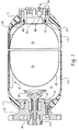
- FIG. 1 is a fragmentary, broken-away axial cross-section of a hydraulic accumulator utilizing the present invention.
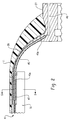
- FIG. 2 is an enlarged, fragmentary axial cross-section, similar to FIG. 1, illustrating the gas collecting means of the present invention within the accumulator housing.
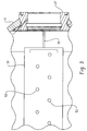
- FIG. 3 is an enlarged, fragmentary view, taken in an upward direction in FIG. 2, but on a somewhat smaller scale than FIG. 2, illustrating the gas collection means of the present invention.
- FIG. 4 is a fragmentary view, similar to FIG. 2, and on approximately the same scale, but without showing the accumulator housing, showing in greater detail certain portions of the gas collecting means of the present invention.
- FIG. 5 is a transverse cross-section through the gas collecting means of the present invention, taken on line 5-5 of FIG. 2.
- FIG. 1 is a fragmentary, broken-away, axial cross-section of a typical hydraulic accumulator, modified to include the present invention.
- the accumulator includes a housing 11, defining an internal chamber 11 C.
- the housing 11 may be of any suitable configuration, such as spherical, but is shown herein as being cylindrical and horizontally elongated.
- an embodiment of an accumulator being developed by the assignee of the present invention includes a housing which is approximately ten inches in diameter, and approximately forty inches long.
- both a high pressure accumulator and a low pressure accumulator are included in the system. In that particular system, and by way of example only, the present invention is included as part of the low pressure accumulator.
- an oil port ring 13 Disposed within an opening formed at the left end of the housing 11 is an oil port ring 13, and bolted to the ring 13 is a mounting flange member 15, by means of which the accumulator may, by way of example only, be bolted to a manifold block, or to some other type of support structure.
- a sleeve 17 Disposed within the ring 13 and flange member 15 is a sleeve 17 which defines a fluid passage (also referred to hereinafter as a "liquid port") 19, providing fluid communication between the external hydraulic circuit (not shown) and a fluid (liquid) chamber 21 disposed within the housing 11.
- the sleeve 17 supports, for reciprocable movement therein, a valve element 23 which, as is well known to those skilled in the accumulator art, is biased by a spring 25 toward the open position of the valve element 23, as shown in FIG. 1.
- a valve element 23 which, as is well known to those skilled in the accumulator art, is biased by a spring 25 toward the open position of the valve element 23, as shown in FIG. 1.
- the present invention is not limited to any particular type or configuration of fluid port and valve arrangement. All that is essential to the present invention is that the accumulator include some suitable arrangement for communicating pressurized fluid between the external hydraulic circuit and the fluid chamber 21.
- a gas port ring 27 (which is at times hereinafter considered, and referred to, as part of the "housing"), and bolted to the gas port ring 27 is a cap member 29.
- the cap member 29 defines a gas port 30, and disposed within the gas port 30 is a gas charging valve assembly 31, by means of which pressurized gas may be communicated from an external source of pressurized gas into a gas chamber 33 disposed within a bladder 35, in a manner generally well known to those skilled in the art.
- the bladder 35 is molded, or formed by some other suitable means, such that, in the presence of pressurized gas within the gas chamber 33 (and in the absence of substantial hydraulic pressure in the fluid chamber 21), the overall configuration of the bladder 35 will conform generally to that of the housing 11, as it is represented in FIG. 1. As is shown only in FIG. 1, the bladder 35 includes, at its rightward end, an enlarged bead 37 which is retained between the gas port ring 27 and the cap member 29.
- the accumulator is illustrated in FIG. 1 as being horizontally oriented, with the fluid valve element 23 being disposed at one axial end thereof, and the gas charging valve assembly 31 being disposed at the other axial end thereof.
- the fluid valve element 23 being disposed at one axial end thereof
- the gas charging valve assembly 31 being disposed at the other axial end thereof.
- annular (rather than elongated) version of the gas collector of the present invention there would be provided an annular (rather than elongated) version of the gas collector of the present invention, and it would be disposed under the gas port ring 27. Therefore, although the present invention would probably be most effective with the accumulator in the horizontal position shown in FIG. 1, it should be clear that neither configuration nor orientation comprise essential features of the invention.
- the preferred embodiment of the present invention includes the liner 39 because the housing 11 comprises a filament wound (or fiber-reinforced) polymeric housing which, in the absence of the liner 39, could be sufficiently porous to permit the flow therethrough of a small amount of the hydraulic fluid contained in the fluid chamber 21.
- the present invention provides a gas collecting assembly, generally designated 41, a portion of which may also be referred to hereinafter as a "transfer membrane", for reasons which will become apparent to those skilled in the art from a reading and understanding of the rest of the specification.
- the gas collecting assembly 41 would be disposed at or near the "top" of the internal chamber (fluid chamber 21) defined by the housing 11, as is shown in FIGS. 1, 2 and 5.
- the gas collecting assembly 41 it is preferable, for reasons which will become apparent subsequently, for the gas collecting assembly 41 to extend over a major portion of the entire axial extent of the accumulator, although it should be understood that such is not essential to the invention, except as is specifically otherwise noted in the claims.
- the overall accumulator length being about forty inches, as was mentioned previously, the axial length of the gas collecting assembly 41 is about thirty inches.
- the gas collecting assembly 41 includes an internal layer of transfer fabric 43 which would preferably comprise an open-weave fabric, or felt, or open-cell foam, or any other suitable fabric or foam-type material which would not be readily degraded by the particular type of gas being used as the charging gas in the gas chamber 33 of the accumulator.
- the transfer fabric 43 must still allow the passage of the gas (nitrogen or other type of gas) through the body of the fabric.
- the primary function of the transfer fabric 43 is to allow movement of the nitrogen gas which has penetrated to the inside of the gas collecting assembly 41.
- the gas collected within the assembly 41 is the gas which has permeated through the bladder 35, and has risen through the fluid contained within the fluid chamber 21.
- the layer of transfer fabric 43 comprises, over most of the axial length of the assembly 41, a true "layer", approximately as shown in the left-hand portion of FIG. 4.
- the gas collecting assembly 41 further includes an external barrier layer of semi-permeable material 41 a (not shown in FIG. 4, see FIG. 5), which would preferably comprise a polymeric material (such as a silicone rubber), and which will allow the passage (permeation) of gas molecules, but will inhibit the passage of the larger hydraulic fluid molecules. Therefore, as gas rises within the fluid chamber 21, the gas will readily pass through the barrier layer 41 a, and into the transfer fabric 43.
- an external barrier layer of semi-permeable material 41 a (not shown in FIG. 4, see FIG. 5), which would preferably comprise a polymeric material (such as a silicone rubber), and which will allow the passage (permeation) of gas molecules, but will inhibit the passage of the larger hydraulic fluid molecules. Therefore, as gas rises within the fluid chamber 21, the gas will readily pass through the barrier layer 41 a, and into the transfer fabric 43.
- a tube member 45 which has one end 45a (its left in FIGS. 2 and 4) attached, by any suitable means, such as an adhesive connection 47, to the gas collecting assembly 41.
- any suitable means such as an adhesive connection 47
- the left end 45a of the tube 45 is connected to the transfer fabric 43 of the assembly 41, there is a right end 45b of the tube member 45, and the right end 45b is received within an angled bore formed in the gas port ring 27, such that the right end 45b of the tube member 45 is in open communication with a gas vent passage 49.
- the tubular member 45 is also referred to hereinafter in the appended claims as a "conduit means to communicate gas”. It may be seen by comparing FIGS. 4 and 5 that the layer of transfer fabric 43 is not uniform over its entire axial length.
- the left-hand portion (in FIG. 4) of the transfer fabric 43 is a true layer, but in the region of the left end 45a of the tube member 45, the transfer fabric 43 includes an enlarged "transition" region which, in the subject embodiment, appears generally wedgeshaped surrounding the left end 45a.
- the structural layer 51 acts as a shield to protect the relatively fragile surface of the gas collecting assembly 41. More specifically, the purpose of the structural layer 51 is to protect the assembly 41 from engagement with the bladder 35, as it moves, while it is expanding or contracting.
- the structural layer 51 comprises a relatively stiff plastic member defining a series of holes 53, by means of which hydraulic fluid and gas can pass through the layer 51, and the gas can permeate the assembly 41, as described previously.
- the structural layer 51 could comprise a fabric member, or a perforated metal member, and it should be understood that the particular details of the layer 51 are not essential features of the invention.
- the opposite edges of the layer 51 are preferably attached (such as by a suitable adhesive) to the surface of the liner 39, thus "enclosing" the gas collecting assembly 41.
- the gas vent passage 49 may be connected either to the atmosphere, in situations where it is acceptable for the particular charging gas to be vented to the atmosphere, or to some sort of gas collection arrangement, which would typically be disposed external to the accumulator, and which is beyond the scope of the present invention.
- the tube member 45 is shown by way of example only, and all that is essential to the present invention is that there be provided some sort of "conduit means", which simply means some arrangement or structure or whatever by means of which the trapped gas can pass from the transfer fabric 43 to another location.
- the gas collecting assembly 41 may comprise a single layer of a semi-permeable material bonded to the liner 39, and bridging a gap, or a series of gaps, in the liner 39. Therefore, in this embodiment, gas which has passed from the liquid in the fluid chamber 21 through the semi-permeable material may then continue through the gaps in the liner 39, and then penetrate (permeate) the porous molecular structure of the composite windings of the housing 11. Eventually, this gas will emerge from the housing 11 as free molecular gas, and pass into the environment. It is believed to be within the ability of those skilled in the art to select the number and size of the openings or gaps in the liner 39 so as not to create significant resistance to the movement of gas molecules through the liner 39.
- the tube member 45 and the gas vent passage 49 are not required elements of the invention, and instead, the porous passages through the housing 11 comprise the "conduit means" of the appended claims.
- the gas collecting assembly may comprise a single component, in the form of a semi-permeable material being used as the material for the liner 39, at least over some portion of the "top" inside surface of the housing 11, i.e., the portion wherein the assembly 41 of the main embodiment resides.
- the liner 39 (or a local portion thereof) could comprise the same material as would be used for the semi-permeable material 41 a in the primary embodiment.
- the tube member 45 and the gas vent passage 49 are again not required elements of the invention, and instead, that portion of the liner comprises the "means for receiving and collecting gas” for purposes of the appended claims, and the porous passages through the liner 39 and through the housing 11 comprise the "conduit means" of the appended claims.
- the present invention has been illustrated and described in connection with an embodiment in which the gas chamber 33 is surrounded by the liquid chamber 21, it should be understood that the present invention is not so limited. Instead, the bladder 35 could contain the liquid, and be surrounded by the gas chamber, in which case, the gas collecting assembly 41 would be disposed within the bladder 35 (and probably disposed toward the "top” thereof), and surrounded by the hydraulic fluid. In this embodiment, which is within the scope of the appended claims, unless otherwise specifically noted, the gas which permeates the bladder 35 would pass through the hydraulic fluid and be received by and collected within the assembly 41, and then communicated to the exterior of the accumulator, as described previously.
Landscapes
- Engineering & Computer Science (AREA)
- Physics & Mathematics (AREA)
- Fluid Mechanics (AREA)
- Mechanical Engineering (AREA)
- General Engineering & Computer Science (AREA)
- Chemical & Material Sciences (AREA)
- Analytical Chemistry (AREA)
- Supply Devices, Intensifiers, Converters, And Telemotors (AREA)
Abstract
A gas charging valve (31) is disposed in the gas port (30) to control the admission of high pressure gas. A deformable, semi-permeable separator (35) is disposed within the housing (11) to separate said internal chamber (11C) into a gas chamber (33) in communication with the gas port (30), and a liquid chamber (21) in communication with the liquid port (19). A means (41) is disposed within the liquid chamber (21) for receiving and collecting gas which passes from the gas chamber (33), through the semi-permeable separator (35), and into said liquid chamber (21). Also included is a conduit means (45) having one end (45a) in fluid communication with the gas collecting means (41), and another end (45b) operably associated with the housing (11,27) to communicate gas from the gas collecting means (41) out of said liquid chamber (21).
Description
Claims (9)
- A hydraulic accumulator of the liquid-gas type, comprising a rigid housing (11) defining an internal chamber (11 C) and a gas port (30) and a liquid port (19); a gas charging valve (31) disposed in said gas port (30) to control the admission of high pressure gas; a deformable, semi-permeable separator (35) disposed within said housing (11) to separate said internal chamber (11 C) into a gas chamber (33) in communication with said gas port (30), and a liquid chamber (21) in communication with said liquid port (19); characterized by:(a) means (41) disposed within said liquid chamber (21) for receiving and collecting gas which passes from said gas chamber (33), through said semi-permeable separator (35), into said liquid chamber (21); and(b) conduit means (45) having one end (45a) in fluid communication with said gas collecting means (41), and another end (45b) operably associated with said housing (11,27) to communicate gas from said gas collecting means (41) out of said liquid chamber (21).
- A hydraulic accumulator as claimed in claim 1, characterized by said rigid housing (11) is generally cylindrical and horizontally elongated, said gas port (30) being disposed at one axial end of said housing (11), and said liquid port (19 ) being disposed at the other axial end of said housing.
- A hydraulic accumulator as claimed in claim 2, characterized by said semi-permeable separator comprising an elongated, generally cylindrical, elastically-deformable bladder (35) defining therein said gas chamber (33), and having one end (37) thereof fixed relative to said rigid housing (11) adjacent said gas charging valve (31).
- A hydraulic accumulator as claimed in claim 3, characterized by said generally cylindrical bladder (35) being generally centrally disposed within said internal chamber (11C) defined by said rigid housing (11); said bladder (35) being surrounded by said liquid chamber (21) under most operating conditions of said accumulator.
- A hydraulic accumulator as claimed in claim 4, characterized by said gas collecting means (41) being elongated, and extending axially over at least a major portion of the axial length of said internal chamber (11 C), and being disposed above said bladder (35) when said accumulator is in its operational position.
- A hydraulic accumulator as claimed in claim 1, characterized by said means (41) for receiving and collecting gas comprises a transfer membrane including a gas storage portion (43) through which gas can travel when said transfer membrane is subjected to normal operating pressures in said liquid chamber (21).
- A hydraulic accumulator as claimed in claim 6, characterized by said transfer membrane includes a layer of material (41 a) which is generally permeable to said gas in said gas chamber (33), while being generally impermeable to liquid, said layer of material being disposed between said gas chamber (33) and said gas storage portion (43) of said transfer membrane.
- A hydraulic accumulator of the liquid-gas type, comprising a rigid housing (11) defining an internal chamber (11 C) and a gas port (30) and a liquid port (19); a gas charging valve (31) disposed in said gas port (30) to control the admission of high pressure gas; a deformable, semi-permeable separator (35) disposed within said housing (11) to separate said internal chamber (11 C) into a gas chamber (33) in communication with said gas port (30), and a liquid chamber (21) in communication with said liquid port (19); characterized by:(a) means disposed within said liquid chamber (21) for receiving and collecting gas which passes from said gas chamber (33), through said semi-permeable separator (35), into said liquid chamber (21), said means comprising said rigid housing (11) having disposed therein a liner (39), including at least a portion of which is semi-permeable with respect to said gas; and(b) conduit means having one end in fluid communication with said gas collecting means, and another portion operably associated with said housing (11) to communicate gas from said gas collecting means, said conduit means comprising said rigid housing being formed from a porous filament material which is semi-permeable with respect to said gas .
- A hydraulic accumulator as claimed in claim 8, characterized by said liner (39) comprising a material which is substantially impermeable with respect to said liquid, but generally permeable with respect to said gas.
Applications Claiming Priority (2)
| Application Number | Priority Date | Filing Date | Title |
|---|---|---|---|
| US75220904A | 2004-01-06 | 2004-01-06 | |
| US752209 | 2004-01-06 |
Publications (3)
| Publication Number | Publication Date |
|---|---|
| EP1553307A2 true EP1553307A2 (en) | 2005-07-13 |
| EP1553307A3 EP1553307A3 (en) | 2005-11-02 |
| EP1553307B1 EP1553307B1 (en) | 2008-07-09 |
Family
ID=34592559
Family Applications (1)
| Application Number | Title | Priority Date | Filing Date |
|---|---|---|---|
| EP05000039A Expired - Lifetime EP1553307B1 (en) | 2004-01-06 | 2005-01-03 | Liquid-gas accumulator with device for trapped gas removal |
Country Status (6)
| Country | Link |
|---|---|
| US (1) | US6971411B1 (en) |
| EP (1) | EP1553307B1 (en) |
| JP (1) | JP4868205B2 (en) |
| CN (1) | CN100473844C (en) |
| AU (1) | AU2004244652B2 (en) |
| DE (1) | DE602005007944D1 (en) |
Cited By (3)
| Publication number | Priority date | Publication date | Assignee | Title |
|---|---|---|---|---|
| FR2994466A1 (en) * | 2012-08-13 | 2014-02-14 | Faurecia Sys Echappement | OLEOPNEUMATIC ACCUMULATOR AND METHOD OF MANUFACTURING THE SAME |
| EP2754852A1 (en) * | 2013-01-15 | 2014-07-16 | Services Pétroliers Schlumberger | Downhole pressure compensator |
| WO2016060990A1 (en) * | 2014-10-12 | 2016-04-21 | Key Safety Systems, Inc. | High pressure fire extinguisher |
Families Citing this family (19)
| Publication number | Priority date | Publication date | Assignee | Title |
|---|---|---|---|---|
| US8098765B1 (en) * | 2004-02-23 | 2012-01-17 | Sirf Technology, Inc. | Reducing and sharing computations for GPS signal processing |
| DE102006004120A1 (en) * | 2006-01-25 | 2007-07-26 | Hydac Technology Gmbh | Hydraulic accumulator, has coaxially abutting plastics casings, with poppet valve for controlling supply and extraction of medium |
| JP5102576B2 (en) * | 2007-10-10 | 2012-12-19 | Nok株式会社 | accumulator |
| EP2058527A3 (en) * | 2007-11-08 | 2012-05-30 | Parker-Hannifin Corporation | Lightweight high pressure repairable piston composite accumulator with slip flange |
| US7984731B2 (en) | 2007-11-13 | 2011-07-26 | Parker-Hannifin Corporation | Lightweight high pressure repairable piston tie rod composite accumulator |
| US8038770B2 (en) * | 2008-12-01 | 2011-10-18 | Eaton Corporation | Separator for degassing fluid |
| DE102008061350A1 (en) | 2008-12-10 | 2010-06-17 | Robert Bosch Gmbh | Hydrostatic system with a hydropneumatic accumulator |
| DE102009021463A1 (en) * | 2009-05-15 | 2010-11-18 | Hydac Technology Gmbh | hydraulic accumulator |
| JP2013522566A (en) * | 2010-03-19 | 2013-06-13 | スリーエム イノベイティブ プロパティズ カンパニー | Hydropneumatic conduit with pressure relief device |
| BR112013006563A2 (en) * | 2010-09-22 | 2016-06-07 | Limo Reid Inc | accumulator assembly and accumulator system |
| US8602063B2 (en) * | 2011-02-08 | 2013-12-10 | Hamilton Sundstrand Corporation | Gas over liquid accumulator |
| DE102011111098A1 (en) * | 2011-08-19 | 2013-05-16 | Hydac Technology Gmbh | pressure vessel |
| EP2788660A1 (en) * | 2011-12-05 | 2014-10-15 | Blue Wave Co S.A. | Type-4 tank for cng containment |
| CN103016428A (en) * | 2013-01-06 | 2013-04-03 | 辽宁省电力有限公司铁岭供电公司 | Air bleeder for accumulator |
| CN103206417A (en) * | 2013-05-06 | 2013-07-17 | 布柯玛蓄能器(天津)有限公司 | 70MPa stainless steel diaphragm type energy accumulator |
| DE102015014496A1 (en) * | 2015-11-10 | 2017-05-11 | Hydac Technology Gmbh | degassing |
| CN109441382A (en) * | 2018-12-28 | 2019-03-08 | 易鲁川 | A kind of hydraulic anchor |
| US12269438B2 (en) * | 2020-02-06 | 2025-04-08 | Volvo Truck Corporation | Sensor cleaning system for a vehicle and a method for cleaning a sensor |
| EP4139577A4 (en) * | 2020-03-23 | 2024-07-17 | Advanced Energy Storage, LLC | DEPLOYABLE ENERGY SUPPLY AND MANAGEMENT SYSTEM |
Family Cites Families (17)
| Publication number | Priority date | Publication date | Assignee | Title |
|---|---|---|---|---|
| FR1391050A (en) * | 1964-01-17 | 1965-03-05 | Rech Etudes Production Sarl | Hydropneumatic safety accumulator, applicable in particular to the hydraulic circuits of aerodynes |
| US3368586A (en) * | 1965-09-01 | 1968-02-13 | Bendix Corp | Accumulator |
| US3907000A (en) * | 1974-04-25 | 1975-09-23 | Teledyne Sprague Eng | Hydro-pneumatic flexible bladder accumulator |
| US4032265A (en) * | 1974-07-19 | 1977-06-28 | United States Steel Corporation | Suction stabilizer for reciprocating pumps and stabilizing method |
| US4328836A (en) * | 1980-10-14 | 1982-05-11 | Deere & Company | Pressure vessel |
| GB2104964A (en) * | 1981-08-12 | 1983-03-16 | Christie Hydraulics Ltd | Improvements relating to hydropneumatic accumulators |
| JPS6041401B2 (en) * | 1983-03-28 | 1985-09-17 | 東芝機器株式会社 | lighting equipment |
| JPS6239001A (en) * | 1985-08-14 | 1987-02-20 | 富士電機株式会社 | Voltage non-linear resistance element |
| IT8801234A0 (en) * | 1988-09-05 | 1988-09-05 | Mgz Spa | PROCEDURE FOR THE PRODUCTION OF CHAINS AND OTHER ORNAMENTAL ITEMS WITH SOLID TUBULAR WIRE AND SUCH OBJECTS |
| US5027860A (en) * | 1990-10-25 | 1991-07-02 | The United States Of America As Represented By The Administrator Of The National Aeronautics And Space Administration | Dual diaphragm tank with telltale drain |
| JPH04266601A (en) * | 1991-02-19 | 1992-09-22 | Taiyo Plant Kogyo:Yugen | Accumulator |
| US5427152A (en) * | 1991-09-21 | 1995-06-27 | Hydac Technology Gmbh | Hydraulic accumulator with dividing wall supported by connecting and retaining parts |
| US5520208A (en) * | 1995-04-03 | 1996-05-28 | Accumulators, Inc. | Resilient seal for a liquid-gas accumulator |
| FR2759144B1 (en) * | 1997-02-06 | 1999-04-23 | Olaer Ind Sa | PRESSURE TANK |
| DE10038982A1 (en) * | 1999-08-16 | 2001-03-01 | Luk Lamellen & Kupplungsbau | Liquid reservoir for a hydraulic system incorporates bellows connected to surrounding atmosphere |
| DE10060558A1 (en) * | 2000-11-29 | 2002-06-13 | Bosch Gmbh Robert | Pressure reservoir for vehicle braking system has pressure medium chamber at least partly bounded by partly permeable material enabling gas to escape and preventing pressure medium from escaping |
| US7121304B2 (en) * | 2001-12-19 | 2006-10-17 | The United States Of America As Represented By The Administrator Of The U.S. Environmental Protection Agency | Low permeation hydraulic accumulator |
-
2004
- 2004-12-24 AU AU2004244652A patent/AU2004244652B2/en not_active Ceased
-
2005
- 2005-01-03 DE DE602005007944T patent/DE602005007944D1/en not_active Expired - Lifetime
- 2005-01-03 EP EP05000039A patent/EP1553307B1/en not_active Expired - Lifetime
- 2005-01-06 JP JP2005001652A patent/JP4868205B2/en not_active Expired - Fee Related
- 2005-01-06 CN CNB2005100003034A patent/CN100473844C/en not_active Expired - Fee Related
- 2005-04-08 US US11/101,904 patent/US6971411B1/en not_active Expired - Lifetime
Cited By (5)
| Publication number | Priority date | Publication date | Assignee | Title |
|---|---|---|---|---|
| FR2994466A1 (en) * | 2012-08-13 | 2014-02-14 | Faurecia Sys Echappement | OLEOPNEUMATIC ACCUMULATOR AND METHOD OF MANUFACTURING THE SAME |
| EP2754852A1 (en) * | 2013-01-15 | 2014-07-16 | Services Pétroliers Schlumberger | Downhole pressure compensator |
| WO2014113409A1 (en) * | 2013-01-15 | 2014-07-24 | Services Petroliers Schlumberger | Downhole pressure compensator |
| WO2016060990A1 (en) * | 2014-10-12 | 2016-04-21 | Key Safety Systems, Inc. | High pressure fire extinguisher |
| CN106999745A (en) * | 2014-10-12 | 2017-08-01 | 关键安全体系股份有限公司 | High-pressure extinction device |
Also Published As
| Publication number | Publication date |
|---|---|
| US20050257844A1 (en) | 2005-11-24 |
| EP1553307B1 (en) | 2008-07-09 |
| JP2005195178A (en) | 2005-07-21 |
| DE602005007944D1 (en) | 2008-08-21 |
| AU2004244652A1 (en) | 2005-07-21 |
| US6971411B1 (en) | 2005-12-06 |
| JP4868205B2 (en) | 2012-02-01 |
| CN100473844C (en) | 2009-04-01 |
| EP1553307A3 (en) | 2005-11-02 |
| CN1657789A (en) | 2005-08-24 |
| AU2004244652B2 (en) | 2011-09-29 |
Similar Documents
| Publication | Publication Date | Title |
|---|---|---|
| EP1553307B1 (en) | Liquid-gas accumulator with device for trapped gas removal | |
| JP4938757B2 (en) | Sleeve type accumulator with built-in light weight and low permeability piston | |
| EP2486286B1 (en) | Energy storage system including an expandable accumulator and reservoir assembly | |
| RU2382913C1 (en) | Hydropneumatic accumulator with soft cellular filler | |
| US7121304B2 (en) | Low permeation hydraulic accumulator | |
| US3162213A (en) | Surge attenuating devices | |
| CN102257280B (en) | Accumulator diaphragm unit, manufacturing method thereof, and rock drilling machine including the accumulator diaphragm unit | |
| US7971608B2 (en) | Breathable low pressure accumulator | |
| CN106415024A (en) | Hydropneumatic pressure accumulator | |
| JP2001082402A (en) | Liquid container | |
| CN102227564A (en) | Hydraulic accumulator and method of manufacture | |
| US10843671B2 (en) | Housing block, in particular for a hydraulic unit of an electronically slip-controllable vehicle brake system | |
| CN1643252A (en) | Reciprocable piston with a fluid scavenging system and method of scavenging a fluid | |
| JPH0399968A (en) | Pressure medium reservoir tank | |
| US20020129859A1 (en) | Crimped piston/membrane accumulator | |
| US8038770B2 (en) | Separator for degassing fluid | |
| US6758243B2 (en) | Pressure accumulator, and method for producing the same | |
| JPH03500326A (en) | piston pump | |
| US4533274A (en) | Flexible joint means | |
| JPH0611060A (en) | Air vent | |
| JP2000186701A (en) | Piston type accumulator | |
| SU1099143A1 (en) | Air-liquid spring | |
| JPH09242702A (en) | accumulator | |
| JPH0882301A (en) | Piston type accumulator | |
| JPH03213702A (en) | Accumulator that utilizes compressibility of fluid |
Legal Events
| Date | Code | Title | Description |
|---|---|---|---|
| PUAI | Public reference made under article 153(3) epc to a published international application that has entered the european phase |
Free format text: ORIGINAL CODE: 0009012 |
|
| AK | Designated contracting states |
Kind code of ref document: A2 Designated state(s): AT BE BG CH CY CZ DE DK EE ES FI FR GB GR HU IE IS IT LI LT LU MC NL PL PT RO SE SI SK TR |
|
| AX | Request for extension of the european patent |
Extension state: AL BA HR LV MK YU |
|
| PUAL | Search report despatched |
Free format text: ORIGINAL CODE: 0009013 |
|
| AK | Designated contracting states |
Kind code of ref document: A3 Designated state(s): AT BE BG CH CY CZ DE DK EE ES FI FR GB GR HU IE IS IT LI LT LU MC NL PL PT RO SE SI SK TR |
|
| AX | Request for extension of the european patent |
Extension state: AL BA HR LV MK YU |
|
| 17P | Request for examination filed |
Effective date: 20060206 |
|
| AKX | Designation fees paid |
Designated state(s): DE FR GB IT SE |
|
| 17Q | First examination report despatched |
Effective date: 20060330 |
|
| GRAP | Despatch of communication of intention to grant a patent |
Free format text: ORIGINAL CODE: EPIDOSNIGR1 |
|
| GRAS | Grant fee paid |
Free format text: ORIGINAL CODE: EPIDOSNIGR3 |
|
| GRAA | (expected) grant |
Free format text: ORIGINAL CODE: 0009210 |
|
| AK | Designated contracting states |
Kind code of ref document: B1 Designated state(s): DE FR GB IT SE |
|
| REG | Reference to a national code |
Ref country code: GB Ref legal event code: FG4D |
|
| REF | Corresponds to: |
Ref document number: 602005007944 Country of ref document: DE Date of ref document: 20080821 Kind code of ref document: P |
|
| REG | Reference to a national code |
Ref country code: SE Ref legal event code: TRGR |
|
| PLBE | No opposition filed within time limit |
Free format text: ORIGINAL CODE: 0009261 |
|
| STAA | Information on the status of an ep patent application or granted ep patent |
Free format text: STATUS: NO OPPOSITION FILED WITHIN TIME LIMIT |
|
| 26N | No opposition filed |
Effective date: 20090414 |
|
| PGFP | Annual fee paid to national office [announced via postgrant information from national office to epo] |
Ref country code: GB Payment date: 20131227 Year of fee payment: 10 |
|
| PGFP | Annual fee paid to national office [announced via postgrant information from national office to epo] |
Ref country code: SE Payment date: 20140109 Year of fee payment: 10 |
|
| PGFP | Annual fee paid to national office [announced via postgrant information from national office to epo] |
Ref country code: FR Payment date: 20131223 Year of fee payment: 10 |
|
| REG | Reference to a national code |
Ref country code: SE Ref legal event code: EUG |
|
| GBPC | Gb: european patent ceased through non-payment of renewal fee |
Effective date: 20150103 |
|
| PG25 | Lapsed in a contracting state [announced via postgrant information from national office to epo] |
Ref country code: GB Free format text: LAPSE BECAUSE OF NON-PAYMENT OF DUE FEES Effective date: 20150103 |
|
| REG | Reference to a national code |
Ref country code: FR Ref legal event code: ST Effective date: 20150930 |
|
| PG25 | Lapsed in a contracting state [announced via postgrant information from national office to epo] |
Ref country code: FR Free format text: LAPSE BECAUSE OF NON-PAYMENT OF DUE FEES Effective date: 20150202 Ref country code: SE Free format text: LAPSE BECAUSE OF NON-PAYMENT OF DUE FEES Effective date: 20150104 |
|
| PGFP | Annual fee paid to national office [announced via postgrant information from national office to epo] |
Ref country code: IT Payment date: 20160118 Year of fee payment: 12 Ref country code: DE Payment date: 20160127 Year of fee payment: 12 |
|
| REG | Reference to a national code |
Ref country code: DE Ref legal event code: R119 Ref document number: 602005007944 Country of ref document: DE |
|
| PG25 | Lapsed in a contracting state [announced via postgrant information from national office to epo] |
Ref country code: DE Free format text: LAPSE BECAUSE OF NON-PAYMENT OF DUE FEES Effective date: 20170801 |
|
| PG25 | Lapsed in a contracting state [announced via postgrant information from national office to epo] |
Ref country code: IT Free format text: LAPSE BECAUSE OF NON-PAYMENT OF DUE FEES Effective date: 20170103 |