JP2013522566A - Hydropneumatic conduit with pressure relief device - Google Patents
Hydropneumatic conduit with pressure relief device Download PDFInfo
- Publication number
- JP2013522566A JP2013522566A JP2013500228A JP2013500228A JP2013522566A JP 2013522566 A JP2013522566 A JP 2013522566A JP 2013500228 A JP2013500228 A JP 2013500228A JP 2013500228 A JP2013500228 A JP 2013500228A JP 2013522566 A JP2013522566 A JP 2013522566A
- Authority
- JP
- Japan
- Prior art keywords
- fluid
- pressure
- compressible
- incompressible
- compressible fluid
- Prior art date
- Legal status (The legal status is an assumption and is not a legal conclusion. Google has not performed a legal analysis and makes no representation as to the accuracy of the status listed.)
- Withdrawn
Links
- 238000007599 discharging Methods 0.000 claims abstract 2
- 239000012530 fluid Substances 0.000 claims description 364
- 230000004888 barrier function Effects 0.000 claims description 24
- 238000001914 filtration Methods 0.000 claims description 18
- 238000004891 communication Methods 0.000 claims description 16
- 238000005381 potential energy Methods 0.000 claims description 14
- 238000000034 method Methods 0.000 claims description 13
- 238000001223 reverse osmosis Methods 0.000 claims description 10
- 230000000670 limiting effect Effects 0.000 claims description 2
- 230000008569 process Effects 0.000 claims description 2
- 230000001568 sexual effect Effects 0.000 claims 1
- 239000007788 liquid Substances 0.000 abstract description 3
- XLYOFNOQVPJJNP-UHFFFAOYSA-N water Substances O XLYOFNOQVPJJNP-UHFFFAOYSA-N 0.000 description 17
- 238000010586 diagram Methods 0.000 description 14
- 230000008901 benefit Effects 0.000 description 9
- IJGRMHOSHXDMSA-UHFFFAOYSA-N Atomic nitrogen Chemical compound N#N IJGRMHOSHXDMSA-UHFFFAOYSA-N 0.000 description 6
- 230000006835 compression Effects 0.000 description 5
- 238000007906 compression Methods 0.000 description 5
- 230000036961 partial effect Effects 0.000 description 5
- 230000002829 reductive effect Effects 0.000 description 4
- 239000007789 gas Substances 0.000 description 3
- 230000007257 malfunction Effects 0.000 description 3
- 239000000463 material Substances 0.000 description 3
- 229910052757 nitrogen Inorganic materials 0.000 description 3
- 239000000356 contaminant Substances 0.000 description 2
- 230000007423 decrease Effects 0.000 description 2
- 229920001971 elastomer Polymers 0.000 description 2
- 239000000806 elastomer Substances 0.000 description 2
- 238000012354 overpressurization Methods 0.000 description 2
- 230000002459 sustained effect Effects 0.000 description 2
- 238000011144 upstream manufacturing Methods 0.000 description 2
- OKTJSMMVPCPJKN-UHFFFAOYSA-N Carbon Chemical compound [C] OKTJSMMVPCPJKN-UHFFFAOYSA-N 0.000 description 1
- 230000009286 beneficial effect Effects 0.000 description 1
- 230000033228 biological regulation Effects 0.000 description 1
- 235000012206 bottled water Nutrition 0.000 description 1
- 229910052799 carbon Inorganic materials 0.000 description 1
- 230000008602 contraction Effects 0.000 description 1
- 238000013270 controlled release Methods 0.000 description 1
- 230000003247 decreasing effect Effects 0.000 description 1
- 238000009792 diffusion process Methods 0.000 description 1
- 239000003651 drinking water Substances 0.000 description 1
- 230000000694 effects Effects 0.000 description 1
- 230000005611 electricity Effects 0.000 description 1
- 239000002360 explosive Substances 0.000 description 1
- 238000005342 ion exchange Methods 0.000 description 1
- 230000000116 mitigating effect Effects 0.000 description 1
- 238000012986 modification Methods 0.000 description 1
- 230000004048 modification Effects 0.000 description 1
- 230000000737 periodic effect Effects 0.000 description 1
- 230000035699 permeability Effects 0.000 description 1
- 239000012466 permeate Substances 0.000 description 1
- 239000002244 precipitate Substances 0.000 description 1
- 230000036316 preload Effects 0.000 description 1
- 230000002028 premature Effects 0.000 description 1
- 239000000047 product Substances 0.000 description 1
- 230000009467 reduction Effects 0.000 description 1
- XZPVPNZTYPUODG-UHFFFAOYSA-M sodium;chloride;dihydrate Chemical compound O.O.[Na+].[Cl-] XZPVPNZTYPUODG-UHFFFAOYSA-M 0.000 description 1
- 239000007787 solid Substances 0.000 description 1
- 239000000243 solution Substances 0.000 description 1
- 229920002994 synthetic fiber Polymers 0.000 description 1
- 230000007704 transition Effects 0.000 description 1
Images


Classifications
-
- E—FIXED CONSTRUCTIONS
- E03—WATER SUPPLY; SEWERAGE
- E03B—INSTALLATIONS OR METHODS FOR OBTAINING, COLLECTING, OR DISTRIBUTING WATER
- E03B7/00—Water main or service pipe systems
- E03B7/07—Arrangement of devices, e.g. filters, flow controls, measuring devices, siphons, valves, in the pipe systems
- E03B7/075—Arrangement of devices for control of pressure or flow rate
-
- F—MECHANICAL ENGINEERING; LIGHTING; HEATING; WEAPONS; BLASTING
- F16—ENGINEERING ELEMENTS AND UNITS; GENERAL MEASURES FOR PRODUCING AND MAINTAINING EFFECTIVE FUNCTIONING OF MACHINES OR INSTALLATIONS; THERMAL INSULATION IN GENERAL
- F16L—PIPES; JOINTS OR FITTINGS FOR PIPES; SUPPORTS FOR PIPES, CABLES OR PROTECTIVE TUBING; MEANS FOR THERMAL INSULATION IN GENERAL
- F16L55/00—Devices or appurtenances for use in, or in connection with, pipes or pipe systems
- F16L55/04—Devices damping pulsations or vibrations in fluids
- F16L55/045—Devices damping pulsations or vibrations in fluids specially adapted to prevent or minimise the effects of water hammer
- F16L55/05—Buffers therefor
- F16L55/052—Pneumatic reservoirs
- F16L55/053—Pneumatic reservoirs the gas in the reservoir being separated from the fluid in the pipe
-
- Y—GENERAL TAGGING OF NEW TECHNOLOGICAL DEVELOPMENTS; GENERAL TAGGING OF CROSS-SECTIONAL TECHNOLOGIES SPANNING OVER SEVERAL SECTIONS OF THE IPC; TECHNICAL SUBJECTS COVERED BY FORMER USPC CROSS-REFERENCE ART COLLECTIONS [XRACs] AND DIGESTS
- Y10—TECHNICAL SUBJECTS COVERED BY FORMER USPC
- Y10T—TECHNICAL SUBJECTS COVERED BY FORMER US CLASSIFICATION
- Y10T137/00—Fluid handling
- Y10T137/0318—Processes
Abstract
非圧縮性液体チャンバから気体チャンバを分離するブラダー又はダイヤフラムを伴うアキュムレータであって、超過圧力の場合に、気体チャンバから気体を放出するための圧力レリーフ弁を有する、アキュムレータ;気体チャンバからの気体を充填及び放出するためのデバイス。 An accumulator with a bladder or diaphragm that separates the gas chamber from the incompressible liquid chamber and having a pressure relief valve for releasing the gas from the gas chamber in the event of overpressure; Device for filling and discharging.
Description
水又は他の液体といった、非圧縮性流体は、しばしば、居住及び商業用途における使用のために供給される。しばしば、かかる流体は、ポンプ又は他の原動力によって、ユーザー又は機械による消費のために、蛇口といった出口に供給される。ユーザー又は機械は、しばしば、流体が、所与の最終用途に対して、タイミング良く送達されることを確実にするように、流体が、比較的高い、維持された流速で供給されることを要求する。例えば、ユーザーは、飲用水で、いくつかの容器を素早く充填したい場合がある。別の例として、商業用コーヒーマシンは、需要が高い間に、顧客のために熱いコーヒーでカラフを充填するように、短時間で、比較的大きな体積の水を必要とする場合がある。かかる用途において、安定した水の流速は、コーヒーの味がバッチ間で同じであるように、一貫して淹れることを達成するためには望ましいことであり得る。 Incompressible fluids, such as water or other liquids, are often supplied for use in residential and commercial applications. Often, such fluid is supplied to an outlet, such as a faucet, for consumption by a user or machine by a pump or other motive force. Users or machines often require that fluid be supplied at a relatively high, sustained flow rate to ensure that the fluid is delivered in a timely manner for a given end use. To do. For example, a user may want to quickly fill some containers with potable water. As another example, a commercial coffee machine may require a relatively large volume of water in a short time to fill carafe with hot coffee for a customer while demand is high. In such applications, a stable water flow rate may be desirable to achieve consistent brewing so that the coffee taste is the same between batches.
典型的に、ポンプ単独では、上記の維持された高い流速の要件を満たすには、不十分である。典型的なポンプは、それが稼動している時のみ、圧力及び流量を供給する。このため、典型的なポンプは、流体が下流のユーザー又は機械によって要求された時に、常に、稼動していることが必要であろう。しかしながら、かかる要求は、しばしば、ポンプが迅速に間欠的に循環させられ得るように、頻繁かつ断続的であり、電気の非効率的な使用、及び恐らく早期のポンプ故障につながる可能性が高い。更に、かかる構成におけるポンプは、典型的に、圧力の低下に依存して、サービスへ切り替わるであろうことから、エンドユーザー又は機械は、流速における望ましくない変動を経験する可能性が高いであろう。 Typically, the pump alone is insufficient to meet the above maintained high flow rate requirements. A typical pump supplies pressure and flow only when it is running. Thus, a typical pump will need to be operating whenever fluid is required by a downstream user or machine. However, such demands are often frequent and intermittent so that the pump can be circulated quickly and intermittently, leading to inefficient use of electricity and possibly premature pump failure. In addition, since the pump in such a configuration will typically switch to service depending on the pressure drop, the end user or machine will likely experience an undesirable variation in flow rate.
上記の問題を軽減するために、ハイドロニューマチックタンクは、蛇口又は他の出口の上流を除き、ポンプの非圧縮性流体ライン下流に取り付けられてもよい。あるタイプのハイドロニューマチックタンクは、圧縮性流体から非圧縮性流体を分離する、内部可撓性障壁を含む。かかるハイドロニューマチックタンクにおいて、可撓性障壁の片側は、典型的に、固定量の圧縮性流体(しばしば、空気又は窒素)が事前装入され、汲み上げられた非圧縮性流体がそれに対して押しやり得るクッションを提供する。ハイドロニューマチックタンクにおける、非圧縮性流体の体積及び圧力の増加は、事前装入された圧縮性流体が、圧縮されるように、可撓性障壁の対応する拡張又は収縮を引き起こす。圧縮性流体のかかる圧縮は、ハイドロニューマチックタンクから出口に、非圧縮性流体を強制するために、後に使用することができる、ポテンシャルエネルギーを格納する。非圧縮性流体は、圧縮性流体に格納されるポテンシャルエネルギーによって、出口へ駆動されるため、ポンプは、維持された流体流量を提供するように、継続的に稼動する必要は無い。むしろ、ポンプは、許容可能なレベルで、ハイドロニューマチックタンクにおける圧力を維持するように、時折、オンに切り替わることのみ必要である。 To alleviate the above problems, the hydropneumatic tank may be installed downstream of the incompressible fluid line of the pump, except upstream of the faucet or other outlet. One type of hydropneumatic tank includes an internal flexible barrier that separates the incompressible fluid from the compressible fluid. In such hydropneumatic tanks, one side of the flexible barrier is typically pre-charged with a fixed amount of compressible fluid (often air or nitrogen) and pumped incompressible fluid is pushed against it. Provide an affordable cushion. The increase in volume and pressure of the incompressible fluid in the hydropneumatic tank causes a corresponding expansion or contraction of the flexible barrier so that the precharged compressive fluid is compressed. Such compression of the compressible fluid stores potential energy that can later be used to force the incompressible fluid from the hydropneumatic tank to the outlet. Since the incompressible fluid is driven to the outlet by the potential energy stored in the compressible fluid, the pump does not need to run continuously to provide a maintained fluid flow rate. Rather, the pump need only be switched on from time to time to maintain the pressure in the hydropneumatic tank at an acceptable level.
実際には、ある機能不全により、非圧縮性流体の圧力が許容可能なレベルを超過する可能性がある。例えば、非圧縮性流体流における圧力スイッチが、故障し、ポンプへの誤ったフィードバックを引き起こし、ポンプが許容可能なレベルを上回る流体の加圧を継続することを可能にし得る。別の例において、非圧縮性流体の予想外の熱膨張が、許容可能なレベルを超過する圧力状態を引き起こし得る。かかる場合、ハイドロニューマチックタンクを、無制御状態で加圧することを可能にしてもよい。無制御超過加圧は、システムの機能不全及び構造的なタンクの故障につながる可能性がある。 In fact, some malfunctions can cause the pressure of the incompressible fluid to exceed acceptable levels. For example, a pressure switch in an incompressible fluid flow may fail and cause false feedback to the pump, allowing the pump to continue to pressurize fluid above acceptable levels. In another example, unexpected thermal expansion of an incompressible fluid can cause a pressure condition that exceeds an acceptable level. In such a case, it may be possible to pressurize the hydropneumatic tank in an uncontrolled state. Uncontrolled overpressurization can lead to system malfunction and structural tank failure.
上記の問題に対する1つの解決策は、非圧縮性流体流に圧力レリーフ弁を提供することである。かかる弁は、動作時、システムから非圧縮性流体を排出することによって、非圧縮性流体の圧力規制を提供し、このため、その圧力が安全かつ許容可能な動作レベルを超過しないことを確実とすることができる。 One solution to the above problem is to provide a pressure relief valve for the incompressible fluid flow. Such valves provide incompressible fluid pressure regulation by draining incompressible fluid from the system during operation, thus ensuring that the pressure does not exceed safe and acceptable operating levels. can do.
残念ながら、非圧縮性流体流における圧力レリーフ弁の提供は、根本的な問題を隠すのみに過ぎず、それを検出されないまま存続させることが可能である。例えば、非圧縮性流体流における圧力レリーフ弁の流体出口は、しばしば、排出された流体(しばしば、加圧される、及び/又は熱い)が、排水管へ下方に、かつエンドユーザー又は機械から離れて、安全に経路をたどるように、排水管に直接汲み上げられる。排出された流体のこの自動的な再経路決定のため、多忙な作業者は、超過圧力状態が発生していることに気づかない場合がある。その兆候に気づいていないことで、彼らは、望ましくない超過圧力を引き起こしている根本的な状態に気づいていない可能性がより高い。 Unfortunately, the provision of a pressure relief valve in an incompressible fluid flow only hides the underlying problem and it can be left undetected. For example, the pressure relief valve fluid outlet in an incompressible fluid flow often causes the discharged fluid (often pressurized and / or hot) to flow down into the drain and away from the end user or machine. In order to safely follow the path, it is pumped directly to the drain pipe. Due to this automatic rerouting of the drained fluid, a busy worker may not be aware that an overpressure condition has occurred. By not being aware of the signs, they are more likely not aware of the underlying condition causing the undesirable overpressure.
更に、超過圧力状態が非圧縮性流体流において存続することが可能であるため、圧力レリーフ弁は、繰り返し作動されることが可能であり、潜在的に、最終的に故障につながり得る磨耗を引き起こす。磨耗が故障を引き起こさない場合でさえも、液体流における圧力レリーフ弁の繰り返しの作動は、弁の適切な動作を妨げる、非圧縮性流体における溶解された固体又は他の汚染物質をもたらす可能性がある。経時的に、かかる汚染物質は、圧力レリーフ弁が、汚染、腐食、又は急止することを引き起こし、最終的に、弁の故障につながり得る。 Furthermore, because the overpressure condition can persist in incompressible fluid flow, the pressure relief valve can be operated repeatedly, potentially causing wear that can ultimately lead to failure. . Even if wear does not cause failure, repeated actuation of the pressure relief valve in the liquid flow can result in dissolved solids or other contaminants in the incompressible fluid that prevent proper operation of the valve. is there. Over time, such contaminants can cause the pressure relief valve to become contaminated, corroded, or suddenly stopped, eventually leading to valve failure.
かかる圧力レリーフ弁が故障した場合、非圧縮性流体流は、チェックされずに加圧されることが可能となり得、潜在的に、ハイドロニューマチックタンクにおける、周期的又は維持された不安全な圧力につながる。 If such a pressure relief valve fails, the incompressible fluid flow may be able to be pressurized without being checked, potentially leading to periodic or maintained unsafe pressure in the hydropneumatic tank. Leads to.
ハイドロニューマチックタンクにおける、許容不可能な超過圧力状態を軽減することを助力することができるシステムに対する必要性が存在する。また、エンドユーザー及び作業者に、超過加圧を引き起こしている根本的な状態の存在を警告しつつ、ハイドロニューマチックタンクにおける、許容不可能な超過圧力状態を軽減することを助力することができるシステムに対する必要性も存在する。また、タンクの故障時に放出可能なエネルギーが低減されるように、ハイドロニューマチックタンクに格納されるポテンシャルエネルギーを減少させることができるシステムに対する必要性も存在する。 There is a need for a system that can help alleviate unacceptable overpressure conditions in hydropneumatic tanks. It can also help end users and workers to mitigate unacceptable overpressure conditions in hydropneumatic tanks while alerting them to the existence of fundamental conditions that are causing overpressure. There is also a need for a system. There is also a need for a system that can reduce the potential energy stored in a hydropneumatic tank so that the energy that can be released in the event of a tank failure is reduced.
本開示は、超過圧力状態が、対応する非圧縮性流体において発生するときに、ハイドロニューマチック導管から圧縮性流体を放出することができる、ハイドロニューマチックシステムを提供する。導管から圧縮性流体を放出することによって、本開示に従う、例示的なハイドロニューマチックシステムは、圧縮のために利用可能な圧縮性流体の量を低減し、このため、ポテンシャルエネルギーを格納するための導管の容量を低減することができる。本開示に従う、例示的なハイドロニューマチックシステムは、ポテンシャルエネルギーを格納するための導管の容量を低減することができるため、ハイドロニューマチックシステムの全体的な流動性能利益は、低減され、かつ最終的に、経時的に排除され、このため、エンドユーザーに、非圧縮性流体の許容不可能な超過加圧を引き起こす状態の存在を警告することができる。本開示に従う、ポテンシャルエネルギーを格納するための導管の容量を低減することの更なる利益は、導管が構造的に故障した場合に、放出可能なエネルギーの量における低減である。 The present disclosure provides a hydropneumatic system that can release a compressible fluid from a hydropneumatic conduit when an overpressure condition occurs in the corresponding incompressible fluid. By releasing the compressible fluid from the conduit, an exemplary hydropneumatic system according to the present disclosure reduces the amount of compressible fluid available for compression, and thus for storing potential energy. The capacity of the conduit can be reduced. Because the exemplary hydropneumatic system according to the present disclosure can reduce the capacity of the conduit for storing potential energy, the overall flow performance benefit of the hydropneumatic system is reduced and ultimately This can be eliminated over time, thus alerting the end user of the presence of a condition that causes unacceptable over-pressurization of the incompressible fluid. A further benefit of reducing the capacity of a conduit for storing potential energy according to the present disclosure is a reduction in the amount of energy that can be released if the conduit structurally fails.
一態様において、本開示は、非圧縮性流体部分と、第1の圧力で圧縮性流体を含有するための圧縮性流体部分であって、非圧縮性流体部分と圧力連通し、かつ可撓性障壁によって非圧縮性流体部分から分離された圧縮性流体部分、を備える、流体導管を備えるハイドロニューマチックシステムを提供する。かかる実施形態は、更に、第2の圧力で非圧縮性流体を非圧縮性流体部分に供給するための非圧縮性流体源であって、第1の圧力が第2の圧力と実質的均衡にある、非圧縮性流体源を備える。かかる実施形態は、更に、非圧縮性流体部分と流体連通している非圧縮性流体出口と、第1の圧力が、閾値圧力を超過する時に、流体導管から圧縮性流体のうちの少なくとも一部分を放出するように、圧縮性流体部分と流体連通している圧力レリーフ装置と、を備える。 In one aspect, the present disclosure provides an incompressible fluid portion and a compressible fluid portion for containing the compressible fluid at a first pressure, in pressure communication with the incompressible fluid portion, and flexible A hydropneumatic system comprising a fluid conduit comprising a compressible fluid portion separated from an incompressible fluid portion by a barrier. Such an embodiment is further an incompressible fluid source for supplying an incompressible fluid to the incompressible fluid portion at a second pressure, wherein the first pressure is substantially balanced with the second pressure. A source of incompressible fluid is provided. Such an embodiment further includes an incompressible fluid outlet in fluid communication with the incompressible fluid portion and at least a portion of the compressible fluid from the fluid conduit when the first pressure exceeds a threshold pressure. A pressure relief device in fluid communication with the compressible fluid portion for release.
一部の実施形態において、可撓性障壁は、拡張可能なブラダー(bladder)を備える。一実施形態において、可撓性障壁は、ダイヤフラム(diaphragm)を備える。 In some embodiments, the flexible barrier comprises an expandable bladder. In one embodiment, the flexible barrier comprises a diaphragm.
一態様において、非圧縮性流体源は、濾過システムを備える。かかる実施形態において、濾過システムは、逆浸透濾過エレメントを備えてもよい。 In one aspect, the incompressible fluid source comprises a filtration system. In such embodiments, the filtration system may comprise a reverse osmosis filtration element.
一実施形態において、非圧縮性流体源は、流体ポンプを備える。かかる実施形態において、流体ポンプは、井戸ポンプを備えてもよい。 In one embodiment, the incompressible fluid source comprises a fluid pump. In such embodiments, the fluid pump may comprise a well pump.
一部の実施形態において、ハイドロニューマチックシステムは、更に、圧縮性流体部分と流体連通している第1の圧縮性流体装入ポートを備える。一部のかかる実施形態において、圧力レリーフ装置は、第1の圧縮性流体装入ポートに接続される。一実施形態において、圧力レリーフ装置は、第1の圧縮性流体装入ポートに螺着可能に接続される。 In some embodiments, the hydropneumatic system further comprises a first compressible fluid inlet port in fluid communication with the compressible fluid portion. In some such embodiments, the pressure relief device is connected to the first compressible fluid charge port. In one embodiment, the pressure relief device is threadably connected to the first compressible fluid inlet port.
一部の実施形態において、第1の圧縮性流体装入ポートは、第1のバネで補助されたポペット弁を備える。一部のかかる実施形態において、圧力レリーフ装置は、第1のバネで補助されたポペット弁を押圧するための弁押圧部材を備える。 In some embodiments, the first compressible fluid input port comprises a poppet valve assisted by a first spring. In some such embodiments, the pressure relief device comprises a valve pressing member for pressing a poppet valve assisted by a first spring.
一実施形態において、ハイドロニューマチックシステムは、圧力レリーフ装置が第1の圧縮性流体装入ポートに接続されつつ、圧縮性流体部分と流体連通し、かつ、アクセス可能である、第2の圧縮性流体装入ポートを更に備える。 In one embodiment, the hydropneumatic system has a second compressibility that is in fluid communication with and accessible to the compressible fluid portion while the pressure relief device is connected to the first compressible fluid inlet port. A fluid charging port is further provided.
一態様において、本開示は、上で説明されるようなハイドロニューマチックシステムであって、非圧縮性流体源が、第2の圧力を動作圧力に制御するための圧力制御デバイスを備え、動作圧力が、閾値圧力を下回るか、又はそれに等しい、ハイドロニューマチックシステムを提供する。 In one aspect, the present disclosure is a hydropneumatic system as described above, wherein the incompressible fluid source comprises a pressure control device for controlling the second pressure to an operating pressure, the operating pressure Provides a hydropneumatic system that is below or equal to the threshold pressure.
本開示は、更に、流体導管に格納されるポテンシャルエネルギーを制限する方法であって、流体導管の非圧縮性流体部分に、第2の圧力で非圧縮性流体を供給する工程であって、流体導管が、第1の圧力で圧縮性流体を備える圧縮性流体部分を備え、圧縮性流体部分は、第1の圧力が第2の圧力と実質的均衡にあるように、非圧縮性流体部分と圧力連通し、かつ可撓性障壁によって非圧縮性流体部分から分離される、工程と、非圧縮性流体を、非圧縮性流体出口に供給する工程と、第1の圧力が閾値圧力を超過する時に、流体導管から圧縮性流体のうちの少なくとも一部分を放出する工程と、を含む方法を提供する。 The present disclosure further provides a method for limiting potential energy stored in a fluid conduit, the method comprising supplying an incompressible fluid at a second pressure to an incompressible fluid portion of the fluid conduit, the fluid comprising: The conduit comprises a compressible fluid portion comprising a compressible fluid at a first pressure, the compressible fluid portion being in an incompressible fluid portion such that the first pressure is in substantial equilibrium with the second pressure. Pressure communicating and separated from the incompressible fluid portion by a flexible barrier; supplying the incompressible fluid to the incompressible fluid outlet; and the first pressure exceeds a threshold pressure Sometimes releasing at least a portion of the compressible fluid from the fluid conduit.
一実施形態において、圧縮性流体部分は、拡張可能なブラダーによって、非圧縮性流体部分から分離される。一部の実施形態において、圧縮性流体部分は、エラストマーの障壁によって、非圧縮性流体部分から分離される。 In one embodiment, the compressible fluid portion is separated from the incompressible fluid portion by an expandable bladder. In some embodiments, the compressible fluid portion is separated from the incompressible fluid portion by an elastomeric barrier.
一部の実施形態において、該方法は、流体導管から十分な量の圧縮性流体を放出して、圧縮性流体部分に、非圧縮性流体出口への非圧縮性流体の供給の補助を停止させる工程を更に含む。 In some embodiments, the method releases a sufficient amount of the compressible fluid from the fluid conduit to cause the compressible fluid portion to stop assisting in supplying the incompressible fluid to the incompressible fluid outlet. The method further includes a step.
一態様において、該方法は、第2の圧力を、閾値圧力を下回るか又はそれに等しい動作圧力に制御する工程を更に含む。 In one aspect, the method further comprises the step of controlling the second pressure to an operating pressure that is below or equal to the threshold pressure.
本明細書において使用される際、「非圧縮性流体」は、実質的に非圧縮性であるが、例えば、変動圧力又は温度状態において、非常にわずかな圧縮を可能にする流体を含む。例えば、水は、それが、ある状態において、極度に小さく圧縮され得るとしても、典型的に「非圧縮性流体」であると見なされる。 As used herein, “incompressible fluid” includes fluids that are substantially incompressible but allow very little compression, for example, at varying pressure or temperature conditions. For example, water is typically considered to be an “incompressible fluid” even though it can be extremely small compressed under certain conditions.
本発明のこれら及び他の態様は、以下の「発明を実施するための形態」から明らかになるであろう。しかし、決して、上記概要は、請求された主題に関する限定として解釈されるべきでなく、主題は、手続処理の間補正することができる添付の特許請求の範囲によってのみ規定される。 These and other aspects of the invention will become apparent from the following Detailed Description. However, in no way should the above summary be construed as a limitation on the claimed subject matter, which is defined only by the appended claims that may be amended during procedural processing.
本明細書全体にわたって、類似の参照数字が類似のエレメントを指す添付図面が参照される。
図1Aは、本開示に従う、例示的なハイドロニューマチックシステム10の概略図である。示されるように、流体導管100は、圧縮性流体部分140及び非圧縮性流体部分120に、内部分離される。圧縮性及び非圧縮性流体122部分は、可撓性障壁110によって分離される。可撓性障壁110は、例えば、図2A及び2Bに描写されるような、拡張可能なブラダーを備えてもよく、又は、図1A〜1Dに示されるようなダイヤフラムであってもよい。典型的に、可撓性障壁110は、圧縮性流体部分140と非圧縮性流体部分120との間の流体連通が無いように、いずれかの流体に不透過性である材料で構築される。しかしながら、例えば、非圧縮性流体122における、可撓性障壁110を通じた、圧縮性気体の遅い拡散による、可撓性障壁110にわたる、あるレベルの非実質的な流体連通は、システムの適切な定常状態動作には影響し得ず、このため、許容され得るということが理解されるものとする。可撓性障壁110に対する可能な材料としては、例えば、エラストマー、並びに強度、弾性、又は透過性を改変するためのエラストマー及び他の材料の合成材料が挙げられる。
FIG. 1A is a schematic diagram of an
図1Aに示されるように、圧縮性流体部分140は、第1の圧力で固定圧力の圧縮性流体142が事前装入され、非圧縮性流体部分120は、第2の圧で非圧縮性流体122を備える。流体導管100における非圧縮性流体122の第2の圧力及び体積は、図1に示されるように、比較的低いため、かつ第1の圧力及び第2の圧力は、実質的均衡にあるため、圧縮性流体142は、最小限に圧縮される。第1の圧力は、圧力レリーフ装置180の閾値圧力を下回るため、圧縮性流体142は、圧縮性流体部分140から放出されない。 As shown in FIG. 1A, the compressible fluid portion 140 is pre-loaded with a fixed pressure compressible fluid 142 at a first pressure and the incompressible fluid portion 120 is an incompressible fluid at a second pressure. 122. Because the second pressure and volume of the incompressible fluid 122 in the fluid conduit 100 is relatively low, as shown in FIG. 1, and because the first pressure and the second pressure are in substantial equilibrium, The compressible fluid 142 is compressed to a minimum. Since the first pressure is below the threshold pressure of the pressure relief device 180, the compressible fluid 142 is not released from the compressible fluid portion 140.
ここで図1Bを参照すると、より多くの非圧縮性流体122が、非圧縮性流体源150から供給され、非圧縮性流体出口170を通って流出することが可能になる。したがって、第2の圧力が増加される。第1の圧力は比例的に増加し、このため、固定量の圧縮性流体142をより小さな体積に圧縮する。このため、図1Bは、圧縮性流体部分140は、圧縮性流体部分140が、クッション、及び要求に応じて、非圧縮性流体出口170から非圧縮性流体122を駆動するための力を供給する十分な程度まで圧縮される、圧縮性流体142を含有する、ハイドロニューマチックシステムに対する典型的な動作状態を描写する。重ねて、第1の圧力は、図1Aに描写される状態に対して増加されているが、圧力レリーフ装置180の閾値圧力を下回ったままであり、圧縮性流体142は、圧縮性流体部分140から放出されない。 Referring now to FIG. 1B, more incompressible fluid 122 can be supplied from the incompressible fluid source 150 and exit through the incompressible fluid outlet 170. Accordingly, the second pressure is increased. The first pressure increases proportionally, thus compressing a fixed amount of compressible fluid 142 to a smaller volume. Thus, FIG. 1B shows that the compressible fluid portion 140 provides a force for the compressible fluid portion 140 to drive the incompressible fluid 122 from the cushion and optionally the incompressible fluid outlet 170. 1 depicts a typical operating condition for a hydropneumatic system containing a compressible fluid 142 that is compressed to a sufficient degree. Again, the first pressure is increased relative to the situation depicted in FIG. 1A, but remains below the threshold pressure of the pressure relief device 180, and the compressible fluid 142 is removed from the compressible fluid portion 140. Not released.
図1Cを見ると、非圧縮性流体源150で生じる超過圧力状態は、第2の圧力を、閾値圧力を上回って更に増加させている。第1の圧力及び第2の圧力は、実質的均衡にあるため、第1の圧力もまた、閾値圧力を上回って増加される。このため、圧縮性流体142のうちの一部分は、第1の圧力が閾値圧力以下のレベルに減少するまで、圧力レリーフ装置180から放出される。圧縮性流体142のうちの一部分が放出されると、ハイドロニューマチックシステム10は、ここで、より少ない量の圧縮性流体142が圧縮性流体部分140に存在することを除き、実質的に、図1Bに示される構成に戻る。より少ない非圧縮性流体122が存在しているため、圧縮性流体部分140は、非圧縮性流体122へのクッション及び力を提供する能力が低く、非圧縮性流体出口170に維持された流体流量を送達する、流体導管100の能力における純損失をもたらす。
Referring to FIG. 1C, the overpressure condition that occurs at the incompressible fluid source 150 further increases the second pressure above the threshold pressure. Since the first pressure and the second pressure are in substantial equilibrium, the first pressure is also increased above the threshold pressure. Thus, a portion of the compressible fluid 142 is released from the pressure relief device 180 until the first pressure decreases to a level below the threshold pressure. When a portion of the compressible fluid 142 is released, the
各超過圧力状態の間に放出される圧縮性流体142の量に依存して、ある数の超過圧力事象は、圧縮性流体142のうちの実質的に全てが、流体導管100から放出された、図1Dに描写される状態を引き起こす。維持された超過圧力状況の間、この放出は、1つの継続的事象において発生し得る。圧縮性流体142のうちの実質的に全てが、流体導管100から放出されると、流体導管100は、非圧縮性流体122に対するクッション又は駆動力の提供を停止する。実際的な影響において、図1Dに描写される状態は、流体導管100がシステムから完全に除去される状況と異ならない。クッション又は駆動力が無いため、ハイドロニューマチックシステム10は、非圧縮性流体出口170に非圧縮性流体122を駆動することを補助する能力を損失し、このため、非圧縮性流体出口170に、圧力及び体積を供給するように、非圧縮性流体源150を残すのみである。上で説明されるように、この状態は、典型的に、許容不可能なシステム性能をもたらす。存続することが可能である場合、この状態は、最終的に、ポンプ故障等につながり得る。
Depending on the amount of compressible fluid 142 released during each overpressure condition, a certain number of overpressure events may cause substantially all of the compressive fluid 142 to be released from the fluid conduit 100. Causes the condition depicted in FIG. 1D. During a sustained overpressure situation, this release can occur in one continuous event. When substantially all of the compressible fluid 142 is released from the fluid conduit 100, the fluid conduit 100 stops providing cushion or driving force to the incompressible fluid 122. In practical effect, the situation depicted in FIG. 1D is no different from the situation where the fluid conduit 100 is completely removed from the system. Because there is no cushion or driving force, the
流体導管100の圧縮性流体部分140上に圧力レリーフ装置180を提供することは、図1A〜1Dに描写される進行が発生することを可能にする。非圧縮性流体出口170での流量性能が減少するにつれて、エンドユーザーは、非圧縮性流体122供給における、超過圧力状態の発生を警告される。この警告機能は、システムへの損傷が発生する前に、かかる超過圧力状態を修復することができるように、エンドユーザーが、適切な技術者に連絡して、かかる超過圧力状態の源を調査することを可能にすることができる。 Providing a pressure relief device 180 on the compressible fluid portion 140 of the fluid conduit 100 allows the progression depicted in FIGS. 1A-1D to occur. As the flow performance at the incompressible fluid outlet 170 decreases, the end user is warned of the occurrence of an overpressure condition in the incompressible fluid 122 supply. This warning feature allows end users to contact the appropriate technicians to investigate the source of such overpressure conditions so that they can be repaired before damage to the system occurs Can make it possible.
図1A〜1Dに描写される進行が発生することを可能にすることの更なる利益は、流体導管100の予想外の構造的故障が発生した場合の、より許容可能な故障モードへのハイドロニューマチックシステム10の遷移である。例えば、現場における、持続して損傷した流体導管100は、構造的に悪化し得る。その悪化した状態において、流体導管100は、その定格圧力よりも下回る圧力で破裂し得る。かかる破裂が発生した場合、流体導管100内に含有されるいかなる流体も、大気に放出される。相当な量の高度に圧縮された圧縮性流体142が、破裂持に、流体導管100に存在する場合、かかる圧縮された流体は、圧縮された流体内のポテンシャルエネルギーが、容易に放出されるように、爆発的に拡張することができる。本開示に従うハイドロニューマチックシステムは、流体導管100内の圧縮性流体142の量を低減し、代わりに、ずっと低いポテンシャルエネルギーを非圧縮性流体122に残すように作用するため、かかる破裂時に放出可能なポテンシャルエネルギーは、先のシステムよりも実質的により低いエネルギーであることが可能である。
A further benefit of allowing the progression depicted in FIGS. 1A-1D to occur is that hydronews to a more acceptable failure mode should an unexpected structural failure of the fluid conduit 100 occur. It is a transition of the
以下で説明される予測的実施例は、仮定的な流体導管100に関して、上で説明される利益を例示する。 The predictive example described below illustrates the benefits described above with respect to the hypothetical fluid conduit 100.
予想される実施例
圧力レリーフ装置180が提供されないことを除き、図1A〜1Bに描写され、以下の表1に示される体積を有する、流体導管100を想定されたい。更に、以下の表1に説明されるような特性を有する、圧縮性及び非圧縮性流体を想定されたい。
Expected Example Consider a fluid conduit 100 depicted in FIGS. 1A-1B and having the volume shown in Table 1 below, except that no pressure relief device 180 is provided. Further, consider compressible and incompressible fluids having properties as described in Table 1 below.

次いで、流体導管が、ハイドロニューマチックシステム10に接続され、非圧縮性流体(水)が、非圧縮性流体源から、流体導管の非圧縮性流体部分120に導入される。次いで、水を、表1からの90psi(620,528Pa)の典型的な絶対流体圧力まで加圧することが可能となる。圧縮性流体圧力及び非圧縮性流体圧力は、実質的均衡にあるため、空気圧力もまた、90psi(620,528Pa)まで加圧される。
The fluid conduit is then connected to the
これらの流体の加圧により、ここで、それらは各々、それらの圧縮された状態で、いくらかのポテンシャルエネルギーを格納する。空気は、圧縮性気体であるため(及び損失を伴わない等温圧縮及び拡張を想定して)、その利用可能なポテンシャルエネルギー(kjの単位)は、以下のように表すことができる: By pressurizing these fluids, they now each store some potential energy in their compressed state. Since air is a compressible gas (and assuming isothermal compression and expansion without loss), its available potential energy (in kj) can be expressed as:
式中、R、T、Po、M空気は、上の表1において見出され、P1は、現在の流体圧力であり、この場合は、90psi(620,528Pa)である。空気が流体導管から放出されなかったため、空気の質量は変化していないことに留意されたい。しかしながら、空気の体積は、圧縮により減少した。理想気体の法則を使用して、空気の新たな体積(V1)を以下のように計算してもよい: Where R, T, P o , M air are found in Table 1 above, where P 1 is the current fluid pressure, in this case 90 psi (620,528 Pa). Note that the mass of air has not changed because air was not released from the fluid conduit. However, the volume of air decreased with compression. Using the ideal gas law, the new volume of air (V 1 ) may be calculated as follows:
反対に、水は、実質的に非圧縮性流体であるため、その利用可能なエネルギー(同様にkjの単位)は、以下として表すことができる: Conversely, since water is a substantially incompressible fluid, its available energy (also kj units) can be expressed as:
式中、γは、上の表1からの水の圧縮性であり、V水は、流体導管における現在の水の体積であり、P1は、現在の流体圧力であり、この場合、90psi(620,528Pa)である。我々は、流体導管における新たな空気の体積を知っているため、V水は、以下として計算することができる: Where γ is the compressibility of water from Table 1 above, V water is the current water volume in the fluid conduit, and P 1 is the current fluid pressure, in this case 90 psi ( 620,528 Pa). Since we know the new air volume in the fluid conduit, V water can be calculated as:
![]()
![]()
表1からの値を当てはめると、以下の結果が出る: Applying the values from Table 1 gives the following results:
次に、内部圧力が表1からの200psi(1,378,951Pa)の上昇した圧力まで増加される、同じ流体導管を考慮されたい。上昇した圧力が、流体導管の安全な動作圧力を満たす、又は超過することを更に想定されたい。上昇した値を式1〜4に当てはめると、以下の結果が出る: Next, consider the same fluid conduit where the internal pressure is increased to an elevated pressure of 200 psi (1,378,951 Pa) from Table 1. It is further assumed that the increased pressure meets or exceeds the safe operating pressure of the fluid conduit. Applying the increased values to Equations 1-4 gives the following results:
ここで、同じ仮定的な流体導管が、本明細書において示され、説明されるように、圧力レリーフ装置180に装着される(この予測的実施例の目的上、「改変された流体導管」)ことを想定されたい。圧力レリーフ装置180が、100psi(689,475Pa)の第1の圧力を超過すると、圧縮性流体を放出するように設定されることを更に想定されたい。 Here, the same hypothetical fluid conduit is attached to the pressure relief device 180 as shown and described herein (for the purposes of this predictive example, a “modified fluid conduit”). I would like to assume that. It is further assumed that the pressure relief device 180 is set to release a compressible fluid when a first pressure of 100 psi (689,475 Pa) is exceeded.
90psi(620,528Pa)の典型的な圧力は、閾値圧力よりも下回るため、改変された流体導管内の体積及びエネルギー状態は、上の表2に示されるものと同一であろう。 Since a typical pressure of 90 psi (620,528 Pa) is below the threshold pressure, the volume and energy state in the modified fluid conduit will be the same as shown in Table 2 above.
しかしながら、改変された流体導管内の水が、表1からの200psi(1,378,951Pa)の上昇した圧力まで増加される時、圧力レリーフ装置180は、改変された流体導管から空気を放出するように起動される。上昇した圧力が維持される場合、又はそれが十分に反復する場合、空気のうちの全ては、改変された流体導管から強制される。この状態において、改変された流体導管に格納される体積及びエネルギーは、以下のとおりである: However, when the water in the modified fluid conduit is increased to an elevated pressure of 200 psi (1,378,951 Pa) from Table 1, the pressure relief device 180 releases air from the modified fluid conduit. To be launched. If the elevated pressure is maintained, or if it repeats sufficiently, all of the air is forced from the modified fluid conduit. In this state, the volume and energy stored in the modified fluid conduit is as follows:
当業者によって理解されるように、本開示は、予測的実施例において説明される実施形態によって制限されない。更に、本開示のある利益を例示するために、空気及び水が、圧縮性及び非圧縮性流体として使用されつつ、同等又は類似の利益が、他の圧縮性及び非圧縮性流体を使用して、実現可能であることを理解されたい。 As will be appreciated by those skilled in the art, the present disclosure is not limited by the embodiments described in the predictive examples. Further, to illustrate certain benefits of the present disclosure, air and water are used as compressible and incompressible fluids, while equivalent or similar benefits may be obtained using other compressible and incompressible fluids. Please understand that it is feasible.
−−予測的実施例の終了−−
図2Aは、本開示に従う、別の例示的なハイドロニューマチックシステム10の概略図である。図2Aに描写される実施形態は、可撓性障壁110が、ダイヤフラムではなくむしろ拡張可能なブラダーを備えることを除き、図1Aに示される実施形態に類似する。拡張可能なブラダーは、可撓性障壁110の将来の置換が、望ましい、又は必要であり得る場合、選択されてもよい。かかるシステムにおいて、サービス開口部は、拡張可能なブラダーが除去及び置換されることを可能にするように、流体導管100の上部に提供されてもよい。典型的なダイヤフラムシステムにおいて、図1A〜1Dに示されるように、ダイヤフラムは、置換可能ではなく、新たな流体導管100が、ダイヤフラム故障時には購入されなければならない。
--End of predictive example--
FIG. 2A is a schematic diagram of another exemplary
図2Bは、図2Aのような、例示的なハイドロニューマチックシステム10の概略図である。図2Bの図は、可撓性障壁110が、ダイヤフラムではなく拡張可能なブラダーを備えることを除き、図1Bの図に対応する。
FIG. 2B is a schematic diagram of an
図3に移ると、非圧縮性流体源150が、濾過システム154を備える、図1A〜1Dに描写及び説明されるようなハイドロニューマチックシステム10が示される。示されるように、濾過システム154は、逆浸透濾過エレメントを備える。図3に示される逆浸透システムは、流体ポンプ160が、逆浸透濾過エレメントに給水を供給するためのブースターポンプとして作用するように、上流に配置される、典型的なものである。逆浸透濾過エレメントを通過する水(透過水)は、ハイドロニューマチックシステム10に供給される。濃縮又はブライン水は、流量制限器を通って、排水管に送られる。
Turning to FIG. 3, a
一部のかかるシステムにおいて、圧力制御デバイス158は、非圧縮性流体122と流体連通して提供される。圧力制御デバイス158は、第2の圧力を動作圧力に制御するために、第2の圧力を監視し、流体ポンプ160にフィードバックを提供することができる。しばしば、マイクロコントローラ、機械的圧力スイッチ等を通じて提供される、このフィードバックは、第2の圧力が動作圧力を下回って低下する時、より多くの非圧縮性流体122を供給するように、流体ポンプ160を促すことができる。 In some such systems, a pressure control device 158 is provided in fluid communication with the incompressible fluid 122. The pressure control device 158 can monitor the second pressure and provide feedback to the fluid pump 160 to control the second pressure to the operating pressure. Often provided through a microcontroller, mechanical pressure switch, etc., this feedback provides fluid pump 160 to provide more incompressible fluid 122 when the second pressure drops below the operating pressure. Can be encouraged.
多くの逆浸透システムにおいて、逆浸透濾過エレメントは、比較的高い圧力低下、及び対応する低い流体流速を生成する。このため、水は、しばしば、非圧縮性流体出口170で維持された下流の需要を満たすように、十分な体積流量で逆浸透濾過エレメントにわたって強制することができない。かかる場合、図3に示されるようなハイドロニューマチックシステム10は、増加した流体容量及び駆動力を提供するために有用であり得る。しかしながら、上述のように、超過圧力状態が、流体導管100からの、圧縮性流体142のうちの一部又は全ての(圧力レリーフ装置180を通じた)放出を引き起こす場合、非圧縮性流体出口170での性能は、減退し、最終的に、非ハイドロニューマチックシステムの比較的乏しい性能に戻る。かかる状態は、例えば、圧力制御デバイス158が、誤作動する、又はそうでなければ、流体ポンプ160への適切なフィードバックの提供を停止する場合に、発生し得、このため、第2の圧力が動作圧力を上回って上昇し、最終的に、第1の圧力が圧力レリーフ装置180の閾値圧力を超過することを可能にする。
In many reverse osmosis systems, reverse osmosis filtration elements produce relatively high pressure drops and corresponding low fluid flow rates. For this reason, water often cannot be forced across the reverse osmosis filtration element with sufficient volumetric flow rate to meet the downstream demand maintained at the incompressible fluid outlet 170. In such a case, the
圧縮性流体142のこの制御された放出は、上に説明される利益、即ち、超過圧力状態の軽減、システム流動性能を低減することによる、エンドユーザーへの超過圧力状態の警告、及び流体導管100の構造的故障の深刻度を減少させるための、流体導管100に格納されるポテンシャルエネルギーの低減を提供することができる。 This controlled release of the compressible fluid 142 is beneficial to the benefits described above, namely, overpressure condition mitigation, end-user overpressure condition warning by reducing system flow performance, and fluid conduit 100. The potential energy stored in the fluid conduit 100 can be reduced to reduce the severity of structural failure.
示される濾過システム154は、逆浸透濾過エレメントを備えつつ、本明細書において説明される利益が、他のタイプの濾過システムを使用して達成可能であることを理解されたい。例えば、本開示に従う実施形態において、濾過システム154が、1つ以上の炭素ブロック、沈殿物フィルタ、イオン交換フィルタ等を備えてもよいことが想定される。 It will be appreciated that the filtration system 154 shown comprises a reverse osmosis filtration element while the benefits described herein can be achieved using other types of filtration systems. For example, in embodiments according to the present disclosure, it is envisioned that the filtration system 154 may include one or more carbon blocks, precipitate filters, ion exchange filters, and the like.
図4は、非圧縮性流体源150が、流体ポンプ160を備える、図1A〜1Dに描写及び説明されるような、例示的なハイドロニューマチックシステム10の概略図である。1つのかかる実施形態において、圧力制御デバイス158は、第2の圧力を監視し、第2の圧力を動作圧力に制御するための流体ポンプ160にフィードバックを提供する。
FIG. 4 is a schematic diagram of an
ここで、図5を参照すると、流体導管100が、第1の圧縮性流体装入ポート104と、圧力レリーフ装置180を備える、例示的なハイドロニューマチックシステム10の部分的な詳細概略図が示される。第1の圧縮性流体装入ポート104は、典型的に、圧縮性流体部分140を圧縮性流体142で装入又は充填するために使用される。場合によっては、圧縮性流体142は、流体導管100が使用される前に、初期圧力まで事前装入される。例えば、流体導管100が、エンドユーザーに出荷される前に、第1の圧縮性流体装入ポート104は、その範囲内の全ての値を含む、1psi(6,894Pa)、5psi(34,473Pa)、7psi(48,263Pa)、10psi(68,947Pa)、15psi(103,421Pa)、20psi(137,895Pa)、30psi(206,843Pa)、35psi(241,317Pa)、45psi(310,264Pa)、55psi(379,212Pa)、又は更には65psi(448,159Pa)で、圧縮性流体部分140に圧縮性流体142を事前装入するように使用されてもよい。圧縮性流体142は、任意の好適な圧縮性流体142であってもよいが、一般的には空気又は窒素である。ある場合において、窒素は、可撓性障壁110を通って透過する傾向がより少ない可能性がある。
Referring now to FIG. 5, a partial detailed schematic view of an
一実施形態において、第1の圧縮性流体装入ポート104は、第1のバネで補助されたポペット弁を備える。典型的に、第1のバネで補助されたポペット弁は、圧縮性流体142が、圧縮性流体部分140の中に注入させるが、ポペットが、ユーザー又はツールによって、物理的に強制的に開口されない限り、そこから放出されないことを可能にする、一方向弁(又はチェック弁)を備える。一実施形態において、第1のバネで補助されたポペット弁は、シュレーダー弁を備える。典型的なシュレーダー弁において、中央に配置されたバルブコアは、流体が弁を通過することを可能にするように、押圧されなければならない、プランジャを備える。このため、圧縮性流体部分140から圧縮性流体142を注入又は放出するために、いずれかのプランジャが、最初に押圧されなければならないか、又はバルブコア全体が除去されなければならない。第1の流体装入ポートは、代替として、プレスタ弁といった、他の一般的に既知の空気弁を備えてもよい。 In one embodiment, the first compressible fluid inlet port 104 comprises a first spring assisted poppet valve. Typically, a first spring assisted poppet valve causes compressible fluid 142 to be injected into compressible fluid portion 140, but the poppet is not physically forced open by the user or tool. As long as it is equipped with a one-way valve (or check valve) that allows it not to be released from it. In one embodiment, the first spring assisted poppet valve comprises a Schrader valve. In a typical Schroeder valve, the centrally located valve core includes a plunger that must be pressed to allow fluid to pass through the valve. Thus, in order to inject or release compressible fluid 142 from compressible fluid portion 140, either plunger must first be pressed or the entire valve core must be removed. The first fluid input port may alternatively comprise other generally known air valves, such as a presta valve.
図5はまた、圧縮性流体部分140と流体連通する、例示的な圧力レリーフ装置180を描写する。一実施形態において、圧力レリーフ装置180は、圧縮性流体142の第1の圧力が閾値圧力を超過する時、圧縮性流体142が圧縮性流体部分140から放出されることを可能にする、一方向弁(又はチェック弁)を備える。 FIG. 5 also depicts an exemplary pressure relief device 180 in fluid communication with the compressible fluid portion 140. In one embodiment, the pressure relief device 180 allows the compressible fluid 142 to be released from the compressible fluid portion 140 when the first pressure of the compressible fluid 142 exceeds a threshold pressure. A valve (or check valve) is provided.
図6は、流体導管100が、第1の圧縮性流体装入ポート104と、第1の圧縮性流体装入ポート104に接続される圧力レリーフ装置180とを備える、本開示に従う、例示的なハイドロニューマチックシステム10を描写する。一部の実施形態において、第1の圧縮性流体装入ポート104は、圧力レリーフ装置180の螺着可能な接続を可能にするように、螺刻された表面を備える。示されるように、第1の圧縮性流体装入ポート104は、押圧可能なプランジャを備える、第1のバネで補助されたポペット弁を備える。圧力レリーフ装置180は、第1のバネで補助されたポペット弁のプランジャを押圧することができる弁押圧部材を備え、このため、圧縮性流体部分140における圧縮性流体142が、圧力レリーフ装置180にアクセスすることを可能にする。一実施形態において、第1のバネで補助されたポペット弁は、シュレーダー弁を備え、圧力レリーフ装置180は、シュレーダー弁プランジャを押圧するための弁押圧部材を備える。
FIG. 6 illustrates an exemplary fluid conduit 100 according to the present disclosure, comprising a first compressible fluid charge port 104 and a pressure relief device 180 connected to the first compressible fluid charge port 104. 1 depicts a
代替として、シュレーダー弁のバルブコアは、除去されてもよく、弁押圧部材を伴わない圧力レリーフ装置180が、シュレーダー弁に接続されてもよい。バルブコアが除去された、シュレーダー弁に接続するように設計される、圧力レリーフ装置180の一例は、GENUINE INNOVATIONS,Tuscon,Arizonaから入手可能なモデル4110圧力レリーフ弁である。しかしながら、図5に示されるような実施形態において、バルブコアを除去するプロセスが、圧縮性流体142のうちの全て又は一部分を圧縮性流体部分140の外に出すため、バルブコアを除去することは典型的に望ましくない。次いで、圧力レリーフ装置180が、第1の圧縮性流体装入ポート104を被覆するため、より多くの圧縮性流体142を圧縮性流体部分140の中に注入することができない。このため、モデル4110といった製品は、かかる用途においては望ましくない場合がある。 Alternatively, the valve core of the Schröder valve may be removed and a pressure relief device 180 without a valve pressing member may be connected to the Schröder valve. An example of a pressure relief device 180, designed to connect to a Schrader valve, with the valve core removed, is a model 4110 pressure relief valve available from GENINE INNOVATIONS, Tuscon, Arizona. However, in an embodiment such as that shown in FIG. 5, it is typical to remove the valve core because the process of removing the valve core forces all or a portion of the compressible fluid 142 out of the compressible fluid portion 140. Not desirable. The pressure relief device 180 then covers the first compressible fluid inlet port 104 so that more compressible fluid 142 cannot be injected into the compressible fluid portion 140. For this reason, products such as the model 4110 may not be desirable in such applications.
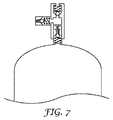
なお別の実施形態を、図7に示す。図7は、流体導管100が、第1の圧縮性流体装入ポート104と、圧力レリーフ装置180とを備え、第2の圧縮性流体装入ポート108が、第1の圧縮性流体装入ポート104に接続される、本開示に従う、例示的なハイドロニューマチックシステム10の部分的な詳細概略図である。かかる実施形態において、ユーザーは、第1の圧縮性流体装入ポート104のバルブコアをそのままにしておくことを選択してもよく、圧縮性流体部分140が圧力レリーフ装置180と流体連通することを可能にするように、圧力レリーフ装置180に弁押圧部材を提供してもよい。代替として、第2の圧縮性流体装入ポート108は、圧縮性流体部分140に装入又は再装入するために提供されるため、ユーザーは、第1の圧縮性流体装入ポート104からバルブコアを除去してもよい。図7に示されるような実施形態において、ユーザーは、有利に、機能的な圧力レリーフ装置180を保持し、かつ同時に圧縮性流体部分140に装入するためのアクセスを維持することができる。
Yet another embodiment is shown in FIG. FIG. 7 shows that the fluid conduit 100 comprises a first compressible fluid charge port 104 and a pressure relief device 180, and the second compressible fluid charge port 108 is a first compressible fluid charge port. 1 is a partial detailed schematic diagram of an
この発明の種々の修正及び変更が発明の趣旨及び範囲から逸脱しないことは、当業者には分かるであろう。本発明は、本明細書において説明した例示の実施形態に制限されないことを理解されたい。 It will be apparent to those skilled in the art that various modifications and variations of the present invention can be made without departing from the spirit and scope of the invention. It should be understood that the present invention is not limited to the exemplary embodiments described herein.
Claims (19)
非圧縮性流体部分、及び
第1の圧力で圧縮性流体を含有するための圧縮性流体部分であって、前記非圧縮性流体部分と圧力連通し、かつ可撓性障壁によって前記非圧縮性流体部分から分離された圧縮性流体部分、を備える、流体導管と、
前記非圧縮性流体部分に第2の圧力で非圧縮性流体を供給するための非圧縮性流体源であって、前記第1の圧力が前記第2の圧力と実質的均衡にある、非圧縮性流体源と、
前記非圧縮性流体部分と流体連通している非圧縮性流体出口と、
前記第1の圧力が閾値圧力を超過する時に、前記流体導管から前記圧縮性流体のうちの少なくとも一部分を放出するように、前記圧縮性流体部分と流体連通している圧力レリーフ装置と、を備える、ハイドロニューマチックシステム。 A hydropneumatic system,
An incompressible fluid portion, and a compressible fluid portion for containing the compressible fluid at a first pressure, wherein the incompressible fluid portion is in pressure communication with the incompressible fluid portion and by a flexible barrier. A fluid conduit comprising a compressible fluid portion separated from the portion;
An incompressible fluid source for supplying an incompressible fluid to the incompressible fluid portion at a second pressure, wherein the first pressure is in substantial equilibrium with the second pressure. A source of sexual fluid,
An incompressible fluid outlet in fluid communication with the incompressible fluid portion;
A pressure relief device in fluid communication with the compressible fluid portion to release at least a portion of the compressible fluid from the fluid conduit when the first pressure exceeds a threshold pressure. , Hydropneumatic system.
前記流体導管の非圧縮性流体部分に、第2の圧力で非圧縮性流体を供給する工程であって、前記流体導管が、第1の圧力で圧縮性流体を備える圧縮性流体部分を備え、前記圧縮性流体部分は、前記第1の圧力が前記第2の圧力と実質的均衡にあるように、前記非圧縮性流体部分と圧力連通し、かつ可撓性障壁によって前記非圧縮性流体部分から分離される、工程と、
前記非圧縮性流体を、非圧縮性流体出口に供給する工程と、
前記第1の圧力が閾値圧力を超過する時に、前記流体導管から前記圧縮性流体のうちの少なくとも一部分を放出する工程と、を含む、方法。 A method for limiting the potential energy stored in a fluid conduit,
Supplying an incompressible fluid at a second pressure to an incompressible fluid portion of the fluid conduit, the fluid conduit comprising a compressible fluid portion comprising a compressible fluid at a first pressure; The compressible fluid portion is in pressure communication with the incompressible fluid portion such that the first pressure is substantially balanced with the second pressure, and the incompressible fluid portion is provided by a flexible barrier. Separated from the process, and
Supplying the incompressible fluid to an incompressible fluid outlet;
Releasing at least a portion of the compressible fluid from the fluid conduit when the first pressure exceeds a threshold pressure.
Applications Claiming Priority (3)
| Application Number | Priority Date | Filing Date | Title |
|---|---|---|---|
| US31567810P | 2010-03-19 | 2010-03-19 | |
| US61/315,678 | 2010-03-19 | ||
| PCT/US2011/028999 WO2011116285A2 (en) | 2010-03-19 | 2011-03-18 | Pressure relief apparatus for hydropneumatic vessel |
Publications (2)
| Publication Number | Publication Date |
|---|---|
| JP2013522566A true JP2013522566A (en) | 2013-06-13 |
| JP2013522566A5 JP2013522566A5 (en) | 2014-04-24 |
Family
ID=44021506
Family Applications (1)
| Application Number | Title | Priority Date | Filing Date |
|---|---|---|---|
| JP2013500228A Withdrawn JP2013522566A (en) | 2010-03-19 | 2011-03-18 | Hydropneumatic conduit with pressure relief device |
Country Status (6)
| Country | Link |
|---|---|
| US (1) | US20130000735A1 (en) |
| EP (1) | EP2547831A2 (en) |
| JP (1) | JP2013522566A (en) |
| CN (1) | CN102803623A (en) |
| BR (1) | BR112012023651A2 (en) |
| WO (1) | WO2011116285A2 (en) |
Families Citing this family (7)
| Publication number | Priority date | Publication date | Assignee | Title |
|---|---|---|---|---|
| CN105972369B (en) * | 2016-07-07 | 2018-12-21 | 滁州普立惠技术服务有限公司 | Petroleum and flow-aiding device in pipeline |
| CN106122662A (en) * | 2016-07-07 | 2016-11-16 | 安庆宜源石油机械配件制造有限责任公司 | Turbine type petroleum pipeline |
| CN107878500A (en) * | 2016-09-30 | 2018-04-06 | 北欧地面支持设备公司 | The anti-freeze method of vehicle on train ice protection system and track |
| EP3385163B1 (en) * | 2017-04-07 | 2024-03-27 | Airbus Operations GmbH | An aircraft comprising a high-pressure water supply and distribution system |
| BR112022014117A2 (en) * | 2020-01-16 | 2022-09-13 | Performance Pulsation Control Inc | REACTIVE FLUID SYSTEM COMPENSATING THERMAL EXPANSION IN NITROGEN REPLACEMENT INSIDE CHARGED PULSE CONTROL EQUIPMENT |
| US10900206B1 (en) * | 2020-02-11 | 2021-01-26 | Ramses S. Nashed | Vapor-liquid mixture-based constant pressure hydropneumatics system |
| EP4242105A1 (en) * | 2022-03-11 | 2023-09-13 | Airbus Operations GmbH | Buffer for storing liquid at a consumer pressure |
Family Cites Families (19)
| Publication number | Priority date | Publication date | Assignee | Title |
|---|---|---|---|---|
| FR429749A (en) * | 1911-05-16 | 1911-09-29 | Antony Bruyant | Pneumatic water hammer device applicable to pressurized liquid pipelines |
| US2775255A (en) * | 1952-07-19 | 1956-12-25 | Robert E Snyder | Apparatus for controlling hydraulic surge |
| US2952211A (en) * | 1958-07-30 | 1960-09-13 | Charles C Saner | Pump |
| US3331117A (en) * | 1966-04-04 | 1967-07-18 | Alphouse A Jacobellis | Method of manufacturing a jacketed spaced-wall accumulator |
| JPS495847B1 (en) * | 1968-06-01 | 1974-02-09 | ||
| US3741692A (en) * | 1970-12-17 | 1973-06-26 | Rupp Co Warren | Surge suppressor for fluid lines |
| US4136714A (en) * | 1976-12-27 | 1979-01-30 | Creavco, Inc. | Accumulator drain closure |
| US4408635A (en) * | 1980-02-14 | 1983-10-11 | Liquid Dynamics, Inc. | Hydropneumatic pulse interceptor |
| US4836409A (en) * | 1988-02-18 | 1989-06-06 | Amtrol Inc. | Integral diaphragm-liner bladder for hydropneumatic tank |
| US6016841A (en) * | 1997-08-27 | 2000-01-25 | Autoliv Asp, Inc. | Accumulator with low permeability flexible diaphragm |
| DE10113415A1 (en) * | 2001-03-20 | 2002-10-02 | Hydac Technology Gmbh | Hydropneumatic pressure accumulator |
| US6860296B2 (en) * | 2001-06-27 | 2005-03-01 | Winston B. Young | High flow nozzle system for flow control in bladder surge tanks |
| DE10233481A1 (en) * | 2002-07-24 | 2004-02-12 | Hydraulik-Ring Gmbh | Storage for a liquid medium |
| AU2004244652B2 (en) * | 2004-01-06 | 2011-09-29 | Eaton Corporation | Trapped gas removal in liquid-gas accumulator |
| US7108016B2 (en) * | 2004-03-08 | 2006-09-19 | The United States Of America As Represented By The Administrator Of The Environmental Protection Agency | Lightweight low permeation piston-in-sleeve accumulator |
| US20070056649A1 (en) * | 2005-09-09 | 2007-03-15 | Chang Hsu P | Pressure container with replaceable bellows |
| CN1749581A (en) * | 2005-10-14 | 2006-03-22 | 王祖林 | Wound diaphragm type accumulator |
| CN201101811Y (en) * | 2007-10-31 | 2008-08-20 | 深圳市轻松科技股份有限公司 | Manual safety valve |
| CN201401376Y (en) * | 2009-05-13 | 2010-02-10 | 王祖林 | Pressure-regulating safety energy accumulator |
-
2011
- 2011-03-18 WO PCT/US2011/028999 patent/WO2011116285A2/en active Application Filing
- 2011-03-18 JP JP2013500228A patent/JP2013522566A/en not_active Withdrawn
- 2011-03-18 CN CN2011800136453A patent/CN102803623A/en active Pending
- 2011-03-18 BR BR112012023651A patent/BR112012023651A2/en not_active IP Right Cessation
- 2011-03-18 EP EP20110712383 patent/EP2547831A2/en not_active Withdrawn
- 2011-03-18 US US13/634,566 patent/US20130000735A1/en not_active Abandoned
Also Published As
| Publication number | Publication date |
|---|---|
| WO2011116285A3 (en) | 2011-11-17 |
| CN102803623A (en) | 2012-11-28 |
| WO2011116285A2 (en) | 2011-09-22 |
| EP2547831A2 (en) | 2013-01-23 |
| US20130000735A1 (en) | 2013-01-03 |
| BR112012023651A2 (en) | 2019-09-24 |
Similar Documents
| Publication | Publication Date | Title |
|---|---|---|
| JP2013522566A (en) | Hydropneumatic conduit with pressure relief device | |
| WO2014155767A1 (en) | Hydraulic device and prime mover device | |
| JP6526984B2 (en) | Gas filling system | |
| US20180128412A1 (en) | Water piping system and control method therefor | |
| CN106345306B (en) | Control method of water purifier | |
| JP5629796B2 (en) | Pump device | |
| NO20120067A1 (en) | Intermediate storage chamber | |
| JP2013522566A5 (en) | ||
| JP6033321B2 (en) | Hot water system | |
| CN105020207A (en) | Dual-redundancy pressure adjusting device having emergent pressure relief | |
| JP2013108622A (en) | Machine tool and motor pump unit | |
| US20140069869A1 (en) | Cross flow filtration system using atmospheric bladder tank | |
| JP2016065567A (en) | Hydrogen station and operation method of hydrogen station | |
| KR102396591B1 (en) | Water treating apparatus | |
| CN103343756B (en) | Liquid twin-stage constant voltage supply station | |
| JP3218896B2 (en) | Natural gas filling equipment | |
| CN203498182U (en) | Reverse osmosis water treatment device | |
| JP5221429B2 (en) | Fire extinguishing equipment | |
| JP5755666B2 (en) | Pressure dehydration apparatus and pressure dehydration method | |
| US20170198689A1 (en) | Displacement pump with fluid reservoir | |
| KR102283706B1 (en) | Water treating apparatus | |
| KR102573494B1 (en) | Water treating apparatus | |
| CN108105174A (en) | Automatically controlled pressure relief mechanism with pressure holding function | |
| JP2009079777A (en) | Relief valve | |
| KR20160025949A (en) | Water treating apparatus |
Legal Events
| Date | Code | Title | Description |
|---|---|---|---|
| A521 | Request for written amendment filed |
Free format text: JAPANESE INTERMEDIATE CODE: A523 Effective date: 20140306 |
|
| A621 | Written request for application examination |
Free format text: JAPANESE INTERMEDIATE CODE: A621 Effective date: 20140306 |
|
| A761 | Written withdrawal of application |
Free format text: JAPANESE INTERMEDIATE CODE: A761 Effective date: 20141014 |