EP1553287B1 - Injection Nozzle - Google Patents
Injection Nozzle Download PDFInfo
- Publication number
- EP1553287B1 EP1553287B1 EP05075610A EP05075610A EP1553287B1 EP 1553287 B1 EP1553287 B1 EP 1553287B1 EP 05075610 A EP05075610 A EP 05075610A EP 05075610 A EP05075610 A EP 05075610A EP 1553287 B1 EP1553287 B1 EP 1553287B1
- Authority
- EP
- European Patent Office
- Prior art keywords
- coating
- nozzle body
- thermal conductivity
- injection nozzle
- nozzle
- Prior art date
- Legal status (The legal status is an assumption and is not a legal conclusion. Google has not performed a legal analysis and makes no representation as to the accuracy of the status listed.)
- Expired - Lifetime
Links
Images

Classifications
-
- F—MECHANICAL ENGINEERING; LIGHTING; HEATING; WEAPONS; BLASTING
- F02—COMBUSTION ENGINES; HOT-GAS OR COMBUSTION-PRODUCT ENGINE PLANTS
- F02M—SUPPLYING COMBUSTION ENGINES IN GENERAL WITH COMBUSTIBLE MIXTURES OR CONSTITUENTS THEREOF
- F02M61/00—Fuel-injectors not provided for in groups F02M39/00 - F02M57/00 or F02M67/00
- F02M61/16—Details not provided for in, or of interest apart from, the apparatus of groups F02M61/02 - F02M61/14
- F02M61/18—Injection nozzles, e.g. having valve seats; Details of valve member seated ends, not otherwise provided for
-
- F—MECHANICAL ENGINEERING; LIGHTING; HEATING; WEAPONS; BLASTING
- F02—COMBUSTION ENGINES; HOT-GAS OR COMBUSTION-PRODUCT ENGINE PLANTS
- F02M—SUPPLYING COMBUSTION ENGINES IN GENERAL WITH COMBUSTIBLE MIXTURES OR CONSTITUENTS THEREOF
- F02M61/00—Fuel-injectors not provided for in groups F02M39/00 - F02M57/00 or F02M67/00
- F02M61/16—Details not provided for in, or of interest apart from, the apparatus of groups F02M61/02 - F02M61/14
- F02M61/166—Selection of particular materials
-
- F—MECHANICAL ENGINEERING; LIGHTING; HEATING; WEAPONS; BLASTING
- F02—COMBUSTION ENGINES; HOT-GAS OR COMBUSTION-PRODUCT ENGINE PLANTS
- F02M—SUPPLYING COMBUSTION ENGINES IN GENERAL WITH COMBUSTIBLE MIXTURES OR CONSTITUENTS THEREOF
- F02M2200/00—Details of fuel-injection apparatus, not otherwise provided for
- F02M2200/06—Fuel-injection apparatus having means for preventing coking, e.g. of fuel injector discharge orifices or valve needles
Definitions
- the first coating may be formed from a material having a higher thermal conductivity than the thermal conductivity of the nozzle body.
- FIG 2 shows another example of a fuel injector in which similar parts to those shown in Figure 1 are denoted with like reference numerals.
- the nozzle body 10 is arranged within an engine cylinder head 20 in a conventional manner, the nozzle body 10 being received within a cap nut 22 which is received within a further bore provided in the cylinder head 20.
- the nozzle body 10 is provided with an annular sealing member 24 which is arranged to provide a seal between the associated engine cylinder into, which fuel is delivered and the upper parts of the injection nozzle and the cylinder head 20.
- suitable materials from which the coating 14a may be formed include aluminium nitride (having a thermal conductivity of 200 W/mK), aluminium (having a thermal conductivity of 204 W/mK), copper (having a thermal conductivity of 384 W/mK), silver (having a thermal conductivity of 407 W/mK) or gold (having a thermal conductivity of 310 W/mK). It will be appreciated, however, that alternative materials having similar thermal properties to the aforementioned materials may also be used for the coating 14a.
Abstract
Description
- This invention relates to an injection nozzle suitable for use in a fuel injector for use in the delivery of fuel under high pressure to a combustion space of a compression ignition internal combustion engine.
- An injection nozzle is exposed, in use, to the temperature within the engine cylinder or other combustion space. As a result, the parts of the injection nozzle which are exposed to such temperatures, for example the seating surface, must be able to withstand such temperatures without significant degradation which would otherwise result in an undesirable reduction in the service life of the injection nozzle. Further, the deposition of fuel lacquer within the injection nozzle, which can undesirably effect, for example, the fuel flow rate through the injector, is accelerated where the nozzle is exposed to high operating temperatures.
- In a known arrangement, in order to protect an injection nozzle from degradation resulting from the temperature within the cylinder or combustion space, a heat shield in the form of a tubular member is provided, the heat shield surrounding a part of the injection nozzle, shielding that part of the nozzle from combustion flames, in use, and conducting heat away from the injection nozzle. Although such an arrangement may result in the service life of the injection nozzle being increased, the provision of the additional heat shield results in the arrangement being relatively complex. Further, in some arrangements, insufficient space may be available to permit the use of such a heat shield.
- It is an object of the invention to provide an injection nozzle in which the disadvantageous effects described hereinbefore are reduced.
- According to a first aspect of the present invention there is provided an injection nozzle for use in delivering fuel to a combustion space. The injection nozzle comprises a nozzle body that comprises a tip region. The tip region projects into the combustion space from an engine cylinder head within which the injection nozzle is received, in use. The tip region is provided with one or more outlet opening. The nozzle body at the tip region is provided with a first coating formed from a material having a first thermal conductivity, and a second coating formed from a material having a second thermal conductivity that is different to the first thermal conductivity of the first coating. The first coating and second coating are provided over at least the part of the tip region which is exposed to the temperature within the combustion space, and are arranged so as to reduce the temperature of at least a part of the nozzle body, in use. The provision of such a coating reduces the temperature to which at least the coated part of the injection nozzle is exposed, and thus reduces the risk of degradation and of the deposition of fuel lacquer, and increases the service life of the injection nozzle.
- The first coating is conveniently provided over at least the part of the exterior of the nozzle body which is exposed to the temperature within the cylinder or other combustion space, in use.
- Typically, the first coating has a thickness of up to 1 mm.
- Conveniently, the nozzle body is received within an engine cylinder head.
- In one embodiment of the invention, the first coating may take the form of a thermally insulating coating, the first coating having a thermal conductivity lower than the thermal conductivity of the nozzle body. Conveniently, the thermally insulating coating may be a ceramic material.
- In the invention, the injection nozzle comprises a second coating formed from a material having a higher thermal conductivity than the thermal conductivity of the nozzle body, wherein the second coating is applied to the first coating to provide a multi-layer coating.
- Alternatively, in a preferred embodiment of the invention, the first coating may be formed from a material having a higher thermal conductivity than the thermal conductivity of the nozzle body.
- The provision of a coating having a higher thermal conductivity than the thermal conductivity of the nozzle body increases the rate of heat transfer from the nozzle body to the cylinder head within which the nozzle body is received. Thus, heat is transferred away from the one or more outlet openings provided in the nozzle body at a higher rate compared with arrangements in which the nozzle body is uncoated or in which the nozzle body is coated with a material having a lower thermal conductivity than the nozzle body.
- Conveniently, the nozzle body may be formed from steel. The first coating is preferably formed from any one of aluminium nitride, aluminium, copper, silver or gold.
- At least a part of the tip region of the nozzle body may be uncoated. This has the effect of further improving the heat transfer away from the or each outlet opening.
- At least a part of the tip region may be coated with a second coating formed from a material having a lower thermal conductivity than the thermal conductivity of the nozzle body. This has the effect of reducing heat transfer to the tip region, whilst the coating of higher thermal conductivity increases heat transfer away from the tip region. Thus, the or each outlet opening reaches a lower operating temperature for given operating conditions.
- Conveniently, the second coating may be formed from a ceramic material. Typically, the second coating has a thickness of up to 1 mm.
- In one embodiment of the invention, in which the first coating has a thermal conductivity higher than that of the nozzle body, the second coating may be formed from a material having a lower thermal conductivity than the thermal conductivity of the nozzle body, wherein the second coating is applied to the first coating to provide a multi-layer coating. Preferably, the second coating is only applied to a part of the first coating which is exposed to the temperature within the combustion space, in use.
- Preferably, the first or second coatings may be bonded to the nozzle body by means of an additional substrate material
- By way of background, a method of assembling an injection nozzle comprises the steps of;
initially providing a coating on the nozzle body of the injection nozzle and,
subsequently forming one or more outlet opening in the nozzle body by drilling through the coating and the nozzle body. - By way of background, another method of assembling an injection nozzle comprises the steps of;
forming one or more outlet opening in the nozzle body of the injection nozzle;
providing shielding means in a region of the nozzle body of the injection nozzle in which the or each outlet opening is formed; and
subsequently providing a coating on the nozzle body. - The invention will further be described, by way of example, with reference to the accompanying drawings in which;
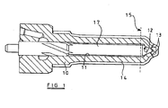
- Figure 1 is a diagrammatic sectional view of an injection nozzle described by way of background to the invention; and
- Figures 2 and 3 are diagrammatic sectional views of other injection nozzles given as background examples in the description.
- By way of background the injection nozzle illustrated in the accompanying drawings comprises a
nozzle body 10 having ablind bore 11 formed therein, theblind bore 11 being supplied with fuel under pressure from a suitable source, for example the common rail of a common rail fuel system. Theblind bore 11 is shaped to define, adjacent the blind end thereof, aseating surface 12. In use, avalve needle 17 is slidable within thebore 11. Thevalve needle 17 is shaped for engagement with theseating surface 12 to control communication between a delivery chamber defined between thebore 11 and thevalve needle 17 upstream of the line of engagement between thevalve needle 17 and theseating surface 12, and at least one outlet opening 13 which communicates with thebore 11 downstream of theseating surface 12. It will be appreciated that when thevalve needle 17 engages theseating surface 12 then fuel is unable to flow from the delivery chamber to the outlet opening(s) 13, thus fuel injection does not take place. Upon movement of thevalve needle 17 away from theseating surface 12, fuel is able to flow from the delivery chamber past the seating surface to the outlet opening(s) 13 and injection of fuel takes place. The position occupied by thevalve needle 17 is controlled by any suitable technique, for example by controlling the fuel pressure within a control chamber defined, in part, by a surface associated with the valve needle, to control the magnitude of a force applied to the valve needle urging the valve needle towards its seating. - Although the description hereinbefore is of a fuel injector intended for use in a common rail type fuel system, it will be appreciated that the invention is not restricted to injectors of this type, and that the invention is applicable to all types of fuel injector, no matter how they are controlled.
- As illustrated by way of example in Figure 1, the exterior of the
nozzle body 10 is provided with acoating 14 of a ceramic material, thecoating 14 being heat resistant and being relatively thermally insulating. Although in Figure 1, theceramic coating 14 is applied over a large part of the exterior of thenozzle body 10, this need not be the case, and thecoating 14 could, if desired, be applied only to the part of thenozzle body 10 to the right of thebroken line 15, this being the part of thenozzle body 10 which, in use, projects into the cylinder or other combustion space of an engine, and being the part containing theseating surface 12, and so being the part of the nozzle body where there is the greatest risk of degradation, and also the region where the deposition of fuel lacquer is most problematic. It is thought that in order to achieve the desired level of thermal protection for the injection nozzle, it may be desirable to provide a coating of thickness up to 1 mm, although it will be appreciated that the example is not limited to this particular thickness of material, and that the thickness of the coating will, in practise, be dependent, to some extent, upon the thermal properties of the coating material and the ability of the material of the nozzle body to withstand degradation resulting from exposure to high temperatures. It will be appreciated that alternative materials having similar heat-shielding properties to a ceramic material may be used for thecoating 14. - As it is thought that the formation of a ceramic coating of thickness up to 1 mm including openings which align with the
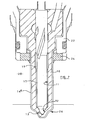
outlet openings 13 may be difficult to achieve, it is envisaged to provide the coating on thenozzle body 10 before the outlet opening(s) 13 are drilled, and that the outlet opening(s) 13 may be drilled through the ceramic material coating and thenozzle body 10 in the same operation. Alternatively, thenozzle body 10 may be shielded in the regions of the outlet opening(s) during the coating process to prevent outlet openings being coated. The coating may additionally or alternatively, if desired, be provided in suitable places on thenozzle body 10, prior to heat treatment of thenozzle body 10, thereby shielding thenozzle body 10 and thus avoiding the formation of a carbon rich layer in places where it is not desired. - Figure 2 shows another example of a fuel injector in which similar parts to those shown in Figure 1 are denoted with like reference numerals. In the fuel injector shown in Figure 2, the
nozzle body 10 is arranged within anengine cylinder head 20 in a conventional manner, thenozzle body 10 being received within acap nut 22 which is received within a further bore provided in thecylinder head 20. Thenozzle body 10 is provided with anannular sealing member 24 which is arranged to provide a seal between the associated engine cylinder into, which fuel is delivered and the upper parts of the injection nozzle and thecylinder head 20. A part of the length of thenozzle body 10 is received within the further bore provided by thecylinder head 20, the nozzle body being provided with atip region 26 which projects through the open end of the further bore into the associated engine cylinder or other combustion space. Thetip region 26 of thenozzle body 10 is that part of thenozzle body 10 which contains theseating surface 12 and theoutlet openings 13, and is therefore that part of thenozzle body 10 where there is the greatest risk of degradation and the region where the deposition of fuel lacquer is most problematic. - By way of background, Figure 2 shows the exterior of the
nozzle body 10 provided with the coating 14a that is formed from a material which has a higherthermal conductivity than the material from which thenozzle body 10 is formed, rather than being formed from a material having a lower thermal conductivity. Usually, thenozzle body 10 is formed from a steel alloy having a thermal conductivity in the region of 50 W/mK. Thus, suitable materials from which the coating 14a may be formed include aluminium nitride (having a thermal conductivity of 200 W/mK), aluminium (having a thermal conductivity of 204 W/mK), copper (having a thermal conductivity of 384 W/mK), silver (having a thermal conductivity of 407 W/mK) or gold (having a thermal conductivity of 310 W/mK). It will be appreciated, however, that alternative materials having similar thermal properties to the aforementioned materials may also be used for the coating 14a. - As the coating 14a applied to the
nozzle body 10 has a higher thermal conductivity than the nozzle body itself, the rate of heat transfer to thenozzle body 10 will be slightly higher than for the case where no coating is applied or where acoating 14 of lower thermal conductivity than that of thenozzle body 10 is applied, as described previously. In the fuel injector shown in Figure 2, heat is transferred from thetip region 26, including the region in which theoutlet openings 13 are formed, to thecylinder head 20 and the sealingmember 24 at a higher rate. The net effect of providing the coating 14a of relatively higher thermal conductivity is therefore to increase the rate of hear transfer away from the region of thenozzle body 10 where the deposition of fuel lacquer is most problematic. Thus, the operating temperature of that part of thetip region 26 containing theoutlet openings 13 is reduced. - As shown in Figure 2, the coating 14a is applied to the part of the
nozzle body 10 which projects from thecap nut 22, and an enlarged diameter region of thenozzle body 10 which is received within thecap nut 22. By applying the coating to the enlarged diameter region of the nozzle body, heat is conducted more effectively to thecap nut 22. - Figure 3 is a further example of a fuel injector described by way of background, in which like reference numerals are used to denote similar parts to those shown in Figures 1 and 2. In this fuel injector, the coating 14a, having a higher thermal conductivity than the thermal conductivity of the
nozzle body 10, is only applied along a part of the exterior of thenozzle body 10, including the part of the exterior of thenozzle body 10 received within thecylinder head 20, such that at least a part of thetip region 26 remains uncoated. This further increases that rate of transfer of heat away from the region of thenozzle body 10 provided with theoutlet openings 13 to the sealingmember 24 and thecylinder head 20, thereby further reducing the operating temperature of this region of thenozzle body 10. It will be appreciated that more or less of the exterior of thenozzle body 10 may be coated, such that more or less of thetip region 26 to that shown in Figure 3 remains uncoated. - In an embodiment of the invention, the part of the
tip region 26 of a fuel injector which is shown to be uncoated in Figure 3 may be coated with a material having a lower thermal conductivity than the thermal conductivity of thenozzle body 10. For example, at least a part of thetip region 26 may be coated with a ceramic material. This provides the further advantage that the rate of heat transfer to the ceramic coated part of thetip region 26 is reduced, whilst the coating 14a of higher thermal conductivity increases the rate of heat transfer away from thetip region 26. Thus, the operating temperature of the part of thetip region 26 provided with theoutlet openings 13 is further reduced. - In order to achieve the desired level of heat transfer away from the
nozzle body 10, it may be desirable to provide a coating 14a having a thickness of up to 1 mm. - In an alternative embodiment of the invention, based on the arrangements shown in Figures 1 to 3, the
nozzle body 10 may be provided with a multi-layer coating, whereby a first coating having a lower thermal conductivity than the thermal conductivity of thenozzle body 10 is applied to the nozzle body 10 (as shown in Figure 1) and a further coating having a higher thermal conductivity than the thermal conductivity of thenozzle body 10 is applied to the first coating. Typically, the further coating may be formed from a material having properties similar to that of the coating 14a, as described previously with reference to Figures 2 and 3. As described previously, the first coating serves to insulate thenozzle body 10, whilst the further coating will aid the conduction of heat away from thenozzle body 10. Alternatively, the order in which the coatings are layered may be reversed such that a first coating having a relatively high thermal conductivity is applied to thenozzle body 10 and an additional coating having a relatively low thermal conductivity is applied to the first coating. Typically, the additional coating may be formed from a material having properties similar to thecoating 14, as described previously with reference to Figure 1. This alternative embodiment is particularly advantageous if the additional coating (i.e. the outermost layer) having a relatively low thermal conductivity is only applied to a lower region of thenozzle body 10, preferably only that region which projects from thecylinder head 20 and is exposed to temperatures within the combustion space. - In any of the embodiments of the invention, and for either a ceramic or other material, an additional substrate material may be applied to the
nozzle body 10 to which acoating 14, 14a is to be applied to ensure satisfactory bonding of the coating(s) to the nozzle body. Additionally, in any of the embodiments of the invention, thenozzle body 10 preferably forms an interference fit within thecylinder head 20, as this improves the effectiveness of thecoating 14, 14a. The effect of the coating(s) is also improved if thenozzle body 10 forms an interference fit within thecap nut 22. - As mentioned hereinbefore, the invention is not restricted to the particular type of injector described hereinbefore, or to injectors suitable for use with common rail type fuel systems. By way of example, the invention is also applicable to fuel pressure actuable injectors suitable for use with rotary distributor pumps, to injectors of the outwardly opening type and to injectors having more than one set of outlet openings and having a valve needle operable between first and second stages of lift.
Claims (9)
- An injection nozzle for use in delivering fuel to a combustion space, the injection nozzle comprising a nozzle body (10), the nozzle body (10) comprising a tip region (26) which projects from an engine cylinder head within which the injection nozzle is received, in use, into the combustion space, the tip region (26) being provided with one or more outlet opening (13) and wherein at the tip region (26) is provided with:a first coating (14; 14a) formed from a material having a first thermal conductivity, anda second coating formed from a material having a second thermal conductivity that is different to the first thermal conductivity of the first coating (14; 14a),wherein the first coating (14; 14a) and second coating are provided over at least the part of the tip region (26) which is exposed to the temperature within the combustion space, and are arranged so as to reduce the temperature of at least a part of the nozzle body (10), in use.
- An injection nozzle according to claim 1, wherein the first coating (14; 14a) and second coating are arranged so as to reduce the temperature of the tip region (26), in use.
- An injection nozzle according to claims 1 and 2, the second coating being applied to the first coating (14; 14a) to provide a multi-layer coating, wherein the first coating (14; 14a) is formed from a material having a higher thermal conductivity than the thermal conductivity of the nozzle body (10) and wherein the second coating is formed from a material having a lower thermal conductivity than the thermal conductivity of the nozzle body (10).
- The injection nozzle as claimed in claims 1 to 3, wherein the second coating is formed from a ceramic material.
- An injection nozzle according to claims 1 and 2, the second coating being applied to the first coating (14; 14a) to provide a multilayer coating, wherein the first coating (14; 14a) is formed from a material having a lower thermal conductivity than the thermal conductivity of the nozzle body (10) and wherein the second coating is formed from a material having a higher thermal conductivity than the thermal conductivity of the nozzle body (10).
- The injection nozzle as claimed in claim 5, wherein the first coating (14; 14a) is formed from a ceramic material.
- The injection nozzle as claimed in any previous claim, comprising an additional substrate material applied to the nozzle body (10), whereby the first coating is bonded to the nozzle body (10) by means of the additional substrate material.
- The injection nozzle as claimed in any previous claim, wherein a part of the tip region (26) of the nozzle body (10) remains uncoated.
- The injection nozzle as claimed in any preceding claim, wherein the exterior of the nozzle body (10) which is exposed to the temperature within the combustion space consists of the tip region (26).
Applications Claiming Priority (5)
| Application Number | Priority Date | Filing Date | Title |
|---|---|---|---|
| GB9920687 | 1999-09-03 | ||
| GBGB9920687.2A GB9920687D0 (en) | 1999-09-03 | 1999-09-03 | Injection nozzle |
| GB9924460 | 1999-10-16 | ||
| GBGB9924460.0A GB9924460D0 (en) | 1999-10-16 | 1999-10-16 | Injection nozzle |
| EP00307569A EP1081374B1 (en) | 1999-09-03 | 2000-09-01 | Injection nozzle |
Related Parent Applications (1)
| Application Number | Title | Priority Date | Filing Date |
|---|---|---|---|
| EP00307569A Division EP1081374B1 (en) | 1999-09-03 | 2000-09-01 | Injection nozzle |
Publications (2)
| Publication Number | Publication Date |
|---|---|
| EP1553287A1 EP1553287A1 (en) | 2005-07-13 |
| EP1553287B1 true EP1553287B1 (en) | 2007-03-07 |
Family
ID=26315901
Family Applications (2)
| Application Number | Title | Priority Date | Filing Date |
|---|---|---|---|
| EP00307569A Expired - Lifetime EP1081374B1 (en) | 1999-09-03 | 2000-09-01 | Injection nozzle |
| EP05075610A Expired - Lifetime EP1553287B1 (en) | 1999-09-03 | 2000-09-01 | Injection Nozzle |
Family Applications Before (1)
| Application Number | Title | Priority Date | Filing Date |
|---|---|---|---|
| EP00307569A Expired - Lifetime EP1081374B1 (en) | 1999-09-03 | 2000-09-01 | Injection nozzle |
Country Status (4)
| Country | Link |
|---|---|
| US (1) | US7331535B2 (en) |
| EP (2) | EP1081374B1 (en) |
| AT (2) | ATE296953T1 (en) |
| DE (2) | DE60020463T2 (en) |
Families Citing this family (20)
| Publication number | Priority date | Publication date | Assignee | Title |
|---|---|---|---|---|
| GB2376047B (en) * | 2001-05-31 | 2005-03-30 | Finch Ltd | Fuel injection devices |
| DE10200044A1 (en) * | 2002-01-03 | 2003-07-24 | Bosch Gmbh Robert | Fuel injection valve, in particular, for an internal combustion engine with external ignition comprises an anti-friction coating in the gap between the bore in the cylinder head and the valve nozzle |
| DE10319694A1 (en) * | 2003-05-02 | 2004-12-02 | Robert Bosch Gmbh | Fuel injector |
| CA2442601C (en) * | 2003-09-26 | 2005-05-24 | Westport Research Inc. | A fuel injection system and method of operation for a gaseous fuelled engine with liquid pilot fuel ignition |
| GB2423353A (en) * | 2005-02-19 | 2006-08-23 | Siemens Ind Turbomachinery Ltd | A Fuel Injector Cooling Arrangement |
| US20070264435A1 (en) * | 2006-05-10 | 2007-11-15 | Kenrick Venett | Material processing system through an injection nozzle |
| JP2008232120A (en) * | 2007-03-23 | 2008-10-02 | Denso Corp | Fuel injection valve |
| DE102008051872A1 (en) * | 2008-10-16 | 2010-04-22 | Albonair Gmbh | two-fluid nozzle |
| JP2010138778A (en) * | 2008-12-11 | 2010-06-24 | Mitsubishi Heavy Ind Ltd | Cooling structure of fuel injection valve |
| EP2439400A1 (en) * | 2010-10-05 | 2012-04-11 | Continental Automotive GmbH | Valve assembly for an injection valve and injection valve |
| DE102012204757A1 (en) * | 2012-03-26 | 2013-09-26 | Robert Bosch Gmbh | Injection device for injecting a medium into a combustion chamber of an internal combustion engine and method for producing an injection device |
| DE102012212039A1 (en) * | 2012-07-10 | 2014-01-16 | Robert Bosch Gmbh | Receiving device for an injection device for injecting a medium into a combustion chamber of an internal combustion engine |
| DE102012214522B3 (en) * | 2012-08-15 | 2014-03-27 | Ford Global Technologies, Llc | Injector |
| DE102013211681A1 (en) * | 2013-06-20 | 2014-12-24 | Robert Bosch Gmbh | Fuel injection valve and device for thermal spray coating |
| DE102013212321A1 (en) | 2013-06-26 | 2014-12-31 | Robert Bosch Gmbh | fuel injector |
| US9410520B2 (en) * | 2013-08-08 | 2016-08-09 | Cummins Inc. | Internal combustion engine including an injector combustion seal positioned between a fuel injector and an engine body |
| US10036355B2 (en) | 2013-08-08 | 2018-07-31 | Cummins Inc. | Heat transferring fuel injector combustion seal with load bearing capability |
| US10605213B2 (en) | 2015-08-21 | 2020-03-31 | Cummins Inc. | Nozzle combustion shield and sealing member with improved heat transfer capabilities |
| JP2019100208A (en) | 2017-11-29 | 2019-06-24 | 株式会社デンソー | Fuel injection valve |
| CN113153599B (en) * | 2021-05-17 | 2024-04-09 | 一汽解放汽车有限公司 | Engine oil nozzle structure and assembly method thereof |
Family Cites Families (19)
| Publication number | Priority date | Publication date | Assignee | Title |
|---|---|---|---|---|
| DE7827497U1 (en) * | 1978-09-15 | 1980-03-06 | Robert Bosch Gmbh, 7000 Stuttgart | HEAT PROTECTION FOR NOZZLES OF INTERNAL COMBUSTION ENGINES |
| DE3404709A1 (en) * | 1984-02-10 | 1985-08-14 | Robert Bosch Gmbh, 7000 Stuttgart | FUEL INJECTION NOZZLE FOR INTERNAL COMBUSTION ENGINES |
| JPS6220672A (en) * | 1985-07-18 | 1987-01-29 | Hitachi Zosen Corp | Fuel valve atomizer for internal-combustion engine |
| DE3623221A1 (en) * | 1986-07-10 | 1988-02-04 | Daimler Benz Ag | Fuel injection nozzle, especially hole-type nozzle for direct injection internal combustion engines |
| US5987882A (en) * | 1996-04-19 | 1999-11-23 | Engelhard Corporation | System for reduction of harmful exhaust emissions from diesel engines |
| US6108189A (en) * | 1996-04-26 | 2000-08-22 | Applied Materials, Inc. | Electrostatic chuck having improved gas conduits |
| DE69706850T2 (en) * | 1996-06-13 | 2002-05-16 | Siemens Ag | ARTICLE WITH PROTECTIVE LAYER CONTAINING AN IMPROVED ANCHOR LAYER AND ITS PRODUCTION |
| JPH1089192A (en) * | 1996-09-10 | 1998-04-07 | Toyota Central Res & Dev Lab Inc | Deposit reducing-type fuel injection valve |
| JPH10274134A (en) * | 1997-03-28 | 1998-10-13 | Zexel Corp | Fuel injection valve |
| US6172331B1 (en) * | 1997-09-17 | 2001-01-09 | General Electric Company | Method and apparatus for laser drilling |
| FR2772432B1 (en) * | 1997-12-12 | 2000-02-18 | Magneti Marelli France | PETROL INJECTOR WITH ANTI-CALAMINE COATING, FOR DIRECT INJECTION |
| US6520154B2 (en) | 1998-02-20 | 2003-02-18 | Delphi Technologies, Inc. | Side feed fuel injector and integrated fuel rail/intake manifold |
| US6260537B1 (en) | 1998-02-20 | 2001-07-17 | Delphi Technologies, Inc. | Side feed fuel injector and integrated fuel rail/intake manifold |
| DE19847839A1 (en) | 1998-10-16 | 2000-04-20 | Gen Motors Corp | Fuel injection device alters pressure in pressure chamber by allowing or interrupting outlet channel flow to actuate nozzle element with pressure chamber connected to fuel pressure line |
| GB9904938D0 (en) | 1999-03-04 | 1999-04-28 | Lucas Ind Plc | Fuel injector |
| GB9916464D0 (en) | 1999-07-14 | 1999-09-15 | Lucas Ind Plc | Fuel injector |
| GB9920144D0 (en) | 1999-08-26 | 1999-10-27 | Lucas Industries Ltd | Fuel injector |
| US6105884A (en) | 1999-09-15 | 2000-08-22 | Delphi Technologies, Inc. | Fuel injector with molded plastic valve guides |
| DE10002366A1 (en) * | 2000-01-20 | 2001-08-02 | Siemens Ag | Fuel injection nozzle for internal combustion engine comprises nozzle body with shaft bore and tip area formed at combustion chamber-side end of nozzle body |
-
2000
- 2000-09-01 EP EP00307569A patent/EP1081374B1/en not_active Expired - Lifetime
- 2000-09-01 AT AT00307569T patent/ATE296953T1/en not_active IP Right Cessation
- 2000-09-01 DE DE60020463T patent/DE60020463T2/en not_active Expired - Lifetime
- 2000-09-01 AT AT05075610T patent/ATE356291T1/en not_active IP Right Cessation
- 2000-09-01 EP EP05075610A patent/EP1553287B1/en not_active Expired - Lifetime
- 2000-09-01 DE DE60033867T patent/DE60033867T2/en not_active Expired - Lifetime
-
2003
- 2003-08-07 US US10/636,112 patent/US7331535B2/en not_active Expired - Fee Related
Also Published As
| Publication number | Publication date |
|---|---|
| EP1081374A2 (en) | 2001-03-07 |
| EP1081374B1 (en) | 2005-06-01 |
| EP1553287A1 (en) | 2005-07-13 |
| US20040026532A1 (en) | 2004-02-12 |
| ATE356291T1 (en) | 2007-03-15 |
| DE60020463D1 (en) | 2005-07-07 |
| DE60033867T2 (en) | 2007-11-22 |
| DE60033867D1 (en) | 2007-04-19 |
| DE60020463T2 (en) | 2006-04-27 |
| ATE296953T1 (en) | 2005-06-15 |
| US7331535B2 (en) | 2008-02-19 |
| EP1081374A3 (en) | 2003-04-16 |
Similar Documents
| Publication | Publication Date | Title |
|---|---|---|
| EP1553287B1 (en) | Injection Nozzle | |
| US10605213B2 (en) | Nozzle combustion shield and sealing member with improved heat transfer capabilities | |
| EP0798460B1 (en) | Method for suppressing formation of deposits on fuel injector and device for injecting fuel | |
| US4434940A (en) | Insulated fuel injection nozzle device and method for manufacturing same | |
| US7021558B2 (en) | Fuel injector having a cooled lower nozzle body | |
| US7926178B2 (en) | Method of fuel nozzle construction | |
| US7070126B2 (en) | Fuel injector with non-metallic tip insulator | |
| US7028918B2 (en) | Fuel injector having a nozzle with improved cooling | |
| US6119658A (en) | Fuel nozzle injecting onto the combustion space of an internal combust | |
| SG104995A1 (en) | Method of forming a coating resistant to deposits and coating formed thereby | |
| EP1116878A2 (en) | Fuel injector | |
| US6053432A (en) | Fuel injector | |
| JPS60187754A (en) | Fuel jet nozzle for internal combustion engine | |
| JPH1089192A (en) | Deposit reducing-type fuel injection valve | |
| JPH10274134A (en) | Fuel injection valve | |
| US4337735A (en) | Light metal cylinder head for a valve-controlled internal combustion engine | |
| US20100055479A1 (en) | Coating for a combustion chamber defining component | |
| GB2238349A (en) | Ceramic faced i.c. engine valves | |
| EP2157312B1 (en) | Fuel injection valve device | |
| JP2007032421A (en) | Fuel injection valve | |
| US20140197245A1 (en) | Arrangement and method for preventing carbon formation in spray guiding structures | |
| CN113153599B (en) | Engine oil nozzle structure and assembly method thereof | |
| KR20040068608A (en) | Fuel injection valve | |
| JPS6026158A (en) | Direct injection type fuel injection valve | |
| JP4033684B2 (en) | Fuel injection device for internal combustion engine |
Legal Events
| Date | Code | Title | Description |
|---|---|---|---|
| PUAI | Public reference made under article 153(3) epc to a published international application that has entered the european phase |
Free format text: ORIGINAL CODE: 0009012 |
|
| 17P | Request for examination filed |
Effective date: 20050406 |
|
| AC | Divisional application: reference to earlier application |
Ref document number: 1081374 Country of ref document: EP Kind code of ref document: P |
|
| AK | Designated contracting states |
Kind code of ref document: A1 Designated state(s): AT BE CH CY DE DK ES FI FR GB GR IE IT LI LU MC NL PT SE |
|
| AKX | Designation fees paid |
Designated state(s): AT BE CH CY DE DK ES FI FR GB GR IE IT LI LU MC NL PT SE |
|
| GRAP | Despatch of communication of intention to grant a patent |
Free format text: ORIGINAL CODE: EPIDOSNIGR1 |
|
| GRAS | Grant fee paid |
Free format text: ORIGINAL CODE: EPIDOSNIGR3 |
|
| GRAA | (expected) grant |
Free format text: ORIGINAL CODE: 0009210 |
|
| AC | Divisional application: reference to earlier application |
Ref document number: 1081374 Country of ref document: EP Kind code of ref document: P |
|
| AK | Designated contracting states |
Kind code of ref document: B1 Designated state(s): AT BE CH CY DE DK ES FI FR GB GR IE IT LI LU MC NL PT SE |
|
| PG25 | Lapsed in a contracting state [announced via postgrant information from national office to epo] |
Ref country code: AT Free format text: LAPSE BECAUSE OF FAILURE TO SUBMIT A TRANSLATION OF THE DESCRIPTION OR TO PAY THE FEE WITHIN THE PRESCRIBED TIME-LIMIT Effective date: 20070307 Ref country code: LI Free format text: LAPSE BECAUSE OF FAILURE TO SUBMIT A TRANSLATION OF THE DESCRIPTION OR TO PAY THE FEE WITHIN THE PRESCRIBED TIME-LIMIT Effective date: 20070307 Ref country code: FI Free format text: LAPSE BECAUSE OF FAILURE TO SUBMIT A TRANSLATION OF THE DESCRIPTION OR TO PAY THE FEE WITHIN THE PRESCRIBED TIME-LIMIT Effective date: 20070307 Ref country code: CH Free format text: LAPSE BECAUSE OF FAILURE TO SUBMIT A TRANSLATION OF THE DESCRIPTION OR TO PAY THE FEE WITHIN THE PRESCRIBED TIME-LIMIT Effective date: 20070307 Ref country code: BE Free format text: LAPSE BECAUSE OF FAILURE TO SUBMIT A TRANSLATION OF THE DESCRIPTION OR TO PAY THE FEE WITHIN THE PRESCRIBED TIME-LIMIT Effective date: 20070307 Ref country code: NL Free format text: LAPSE BECAUSE OF FAILURE TO SUBMIT A TRANSLATION OF THE DESCRIPTION OR TO PAY THE FEE WITHIN THE PRESCRIBED TIME-LIMIT Effective date: 20070307 |
|
| REG | Reference to a national code |
Ref country code: GB Ref legal event code: FG4D |
|
| REG | Reference to a national code |
Ref country code: CH Ref legal event code: EP |
|
| REF | Corresponds to: |
Ref document number: 60033867 Country of ref document: DE Date of ref document: 20070419 Kind code of ref document: P |
|
| REG | Reference to a national code |
Ref country code: IE Ref legal event code: FG4D |
|
| PG25 | Lapsed in a contracting state [announced via postgrant information from national office to epo] |
Ref country code: SE Free format text: LAPSE BECAUSE OF FAILURE TO SUBMIT A TRANSLATION OF THE DESCRIPTION OR TO PAY THE FEE WITHIN THE PRESCRIBED TIME-LIMIT Effective date: 20070607 |
|
| PG25 | Lapsed in a contracting state [announced via postgrant information from national office to epo] |
Ref country code: ES Free format text: LAPSE BECAUSE OF FAILURE TO SUBMIT A TRANSLATION OF THE DESCRIPTION OR TO PAY THE FEE WITHIN THE PRESCRIBED TIME-LIMIT Effective date: 20070618 |
|
| ET | Fr: translation filed | ||
| PG25 | Lapsed in a contracting state [announced via postgrant information from national office to epo] |
Ref country code: PT Free format text: LAPSE BECAUSE OF FAILURE TO SUBMIT A TRANSLATION OF THE DESCRIPTION OR TO PAY THE FEE WITHIN THE PRESCRIBED TIME-LIMIT Effective date: 20070807 |
|
| NLV1 | Nl: lapsed or annulled due to failure to fulfill the requirements of art. 29p and 29m of the patents act | ||
| REG | Reference to a national code |
Ref country code: CH Ref legal event code: PL |
|
| PLBE | No opposition filed within time limit |
Free format text: ORIGINAL CODE: 0009261 |
|
| STAA | Information on the status of an ep patent application or granted ep patent |
Free format text: STATUS: NO OPPOSITION FILED WITHIN TIME LIMIT |
|
| PG25 | Lapsed in a contracting state [announced via postgrant information from national office to epo] |
Ref country code: DK Free format text: LAPSE BECAUSE OF FAILURE TO SUBMIT A TRANSLATION OF THE DESCRIPTION OR TO PAY THE FEE WITHIN THE PRESCRIBED TIME-LIMIT Effective date: 20070307 |
|
| 26N | No opposition filed |
Effective date: 20071210 |
|
| PG25 | Lapsed in a contracting state [announced via postgrant information from national office to epo] |
Ref country code: MC Free format text: LAPSE BECAUSE OF NON-PAYMENT OF DUE FEES Effective date: 20070930 Ref country code: GR Free format text: LAPSE BECAUSE OF FAILURE TO SUBMIT A TRANSLATION OF THE DESCRIPTION OR TO PAY THE FEE WITHIN THE PRESCRIBED TIME-LIMIT Effective date: 20070608 |
|
| GBPC | Gb: european patent ceased through non-payment of renewal fee |
Effective date: 20070901 |
|
| PG25 | Lapsed in a contracting state [announced via postgrant information from national office to epo] |
Ref country code: IE Free format text: LAPSE BECAUSE OF NON-PAYMENT OF DUE FEES Effective date: 20070903 |
|
| PG25 | Lapsed in a contracting state [announced via postgrant information from national office to epo] |
Ref country code: GB Free format text: LAPSE BECAUSE OF NON-PAYMENT OF DUE FEES Effective date: 20070901 |
|
| PG25 | Lapsed in a contracting state [announced via postgrant information from national office to epo] |
Ref country code: CY Free format text: LAPSE BECAUSE OF FAILURE TO SUBMIT A TRANSLATION OF THE DESCRIPTION OR TO PAY THE FEE WITHIN THE PRESCRIBED TIME-LIMIT Effective date: 20070307 |
|
| PG25 | Lapsed in a contracting state [announced via postgrant information from national office to epo] |
Ref country code: LU Free format text: LAPSE BECAUSE OF NON-PAYMENT OF DUE FEES Effective date: 20070901 |
|
| REG | Reference to a national code |
Ref country code: FR Ref legal event code: TP |
|
| REG | Reference to a national code |
Ref country code: FR Ref legal event code: TP Owner name: DELPHI INTERNATIONAL OPERATIONS LUXEMBOURG S.A, LU Effective date: 20140516 |
|
| REG | Reference to a national code |
Ref country code: DE Ref legal event code: R082 Ref document number: 60033867 Country of ref document: DE Representative=s name: MANITZ, FINSTERWALD & PARTNER GBR, DE |
|
| REG | Reference to a national code |
Ref country code: DE Ref legal event code: R081 Ref document number: 60033867 Country of ref document: DE Owner name: DELPHI INTERNATIONAL OPERATIONS LUXEMBOURG S.A, LU Free format text: FORMER OWNER: DELPHI TECHNOLOGIES HOLDING S.A.R.L., BASCHARAGE, LU Effective date: 20140702 Ref country code: DE Ref legal event code: R082 Ref document number: 60033867 Country of ref document: DE Representative=s name: MANITZ, FINSTERWALD & PARTNER GBR, DE Effective date: 20140702 Ref country code: DE Ref legal event code: R082 Ref document number: 60033867 Country of ref document: DE Representative=s name: MANITZ FINSTERWALD PATENTANWAELTE PARTMBB, DE Effective date: 20140702 |
|
| REG | Reference to a national code |
Ref country code: FR Ref legal event code: PLFP Year of fee payment: 16 |
|
| REG | Reference to a national code |
Ref country code: FR Ref legal event code: PLFP Year of fee payment: 17 |
|
| REG | Reference to a national code |
Ref country code: FR Ref legal event code: PLFP Year of fee payment: 18 |
|
| REG | Reference to a national code |
Ref country code: FR Ref legal event code: PLFP Year of fee payment: 19 |
|
| PGFP | Annual fee paid to national office [announced via postgrant information from national office to epo] |
Ref country code: FR Payment date: 20180925 Year of fee payment: 19 Ref country code: IT Payment date: 20180920 Year of fee payment: 19 Ref country code: DE Payment date: 20180927 Year of fee payment: 19 |
|
| REG | Reference to a national code |
Ref country code: DE Ref legal event code: R119 Ref document number: 60033867 Country of ref document: DE |
|
| PG25 | Lapsed in a contracting state [announced via postgrant information from national office to epo] |
Ref country code: DE Free format text: LAPSE BECAUSE OF NON-PAYMENT OF DUE FEES Effective date: 20200401 |
|
| PG25 | Lapsed in a contracting state [announced via postgrant information from national office to epo] |
Ref country code: IT Free format text: LAPSE BECAUSE OF NON-PAYMENT OF DUE FEES Effective date: 20190901 |
|
| PG25 | Lapsed in a contracting state [announced via postgrant information from national office to epo] |
Ref country code: FR Free format text: LAPSE BECAUSE OF NON-PAYMENT OF DUE FEES Effective date: 20190930 |