EP1553281A1 - Vorrichtung zur Reduktion des Austrittslärms von Strahltriebwerken unter Benutzung von oszillierenden Strahlen - Google Patents
Vorrichtung zur Reduktion des Austrittslärms von Strahltriebwerken unter Benutzung von oszillierenden Strahlen Download PDFInfo
- Publication number
- EP1553281A1 EP1553281A1 EP04257993A EP04257993A EP1553281A1 EP 1553281 A1 EP1553281 A1 EP 1553281A1 EP 04257993 A EP04257993 A EP 04257993A EP 04257993 A EP04257993 A EP 04257993A EP 1553281 A1 EP1553281 A1 EP 1553281A1
- Authority
- EP
- European Patent Office
- Prior art keywords
- engine exhaust
- oscillating
- jet
- flow
- gas
- Prior art date
- Legal status (The legal status is an assumption and is not a legal conclusion. Google has not performed a legal analysis and makes no representation as to the accuracy of the status listed.)
- Granted
Links
Images


Classifications
-
- F—MECHANICAL ENGINEERING; LIGHTING; HEATING; WEAPONS; BLASTING
- F02—COMBUSTION ENGINES; HOT-GAS OR COMBUSTION-PRODUCT ENGINE PLANTS
- F02K—JET-PROPULSION PLANTS
- F02K1/00—Plants characterised by the form or arrangement of the jet pipe or nozzle; Jet pipes or nozzles peculiar thereto
- F02K1/06—Varying effective area of jet pipe or nozzle
- F02K1/12—Varying effective area of jet pipe or nozzle by means of pivoted flaps
- F02K1/1292—Varying effective area of jet pipe or nozzle by means of pivoted flaps of three series of flaps, the upstream series having its flaps hinged at their upstream ends on a fixed structure, the internal downstream series having its flaps hinged at their upstream ends on the downstream ends of the flaps of the upstream series and at their downstream ends on the downstream ends of the flaps of the external downstream series hinged at their upstream ends on a substantially axially movable structure
-
- F—MECHANICAL ENGINEERING; LIGHTING; HEATING; WEAPONS; BLASTING
- F02—COMBUSTION ENGINES; HOT-GAS OR COMBUSTION-PRODUCT ENGINE PLANTS
- F02K—JET-PROPULSION PLANTS
- F02K1/00—Plants characterised by the form or arrangement of the jet pipe or nozzle; Jet pipes or nozzles peculiar thereto
- F02K1/28—Plants characterised by the form or arrangement of the jet pipe or nozzle; Jet pipes or nozzles peculiar thereto using fluid jets to influence the jet flow
- F02K1/34—Plants characterised by the form or arrangement of the jet pipe or nozzle; Jet pipes or nozzles peculiar thereto using fluid jets to influence the jet flow for attenuating noise
-
- F—MECHANICAL ENGINEERING; LIGHTING; HEATING; WEAPONS; BLASTING
- F05—INDEXING SCHEMES RELATING TO ENGINES OR PUMPS IN VARIOUS SUBCLASSES OF CLASSES F01-F04
- F05D—INDEXING SCHEME FOR ASPECTS RELATING TO NON-POSITIVE-DISPLACEMENT MACHINES OR ENGINES, GAS-TURBINES OR JET-PROPULSION PLANTS
- F05D2250/00—Geometry
- F05D2250/10—Two-dimensional
- F05D2250/11—Two-dimensional triangular
-
- F—MECHANICAL ENGINEERING; LIGHTING; HEATING; WEAPONS; BLASTING
- F05—INDEXING SCHEMES RELATING TO ENGINES OR PUMPS IN VARIOUS SUBCLASSES OF CLASSES F01-F04
- F05D—INDEXING SCHEME FOR ASPECTS RELATING TO NON-POSITIVE-DISPLACEMENT MACHINES OR ENGINES, GAS-TURBINES OR JET-PROPULSION PLANTS
- F05D2260/00—Function
- F05D2260/96—Preventing, counteracting or reducing vibration or noise
-
- Y—GENERAL TAGGING OF NEW TECHNOLOGICAL DEVELOPMENTS; GENERAL TAGGING OF CROSS-SECTIONAL TECHNOLOGIES SPANNING OVER SEVERAL SECTIONS OF THE IPC; TECHNICAL SUBJECTS COVERED BY FORMER USPC CROSS-REFERENCE ART COLLECTIONS [XRACs] AND DIGESTS
- Y02—TECHNOLOGIES OR APPLICATIONS FOR MITIGATION OR ADAPTATION AGAINST CLIMATE CHANGE
- Y02T—CLIMATE CHANGE MITIGATION TECHNOLOGIES RELATED TO TRANSPORTATION
- Y02T50/00—Aeronautics or air transport
- Y02T50/60—Efficient propulsion technologies, e.g. for aircraft
Definitions
- This invention relates to an apparatus for reducing jet engine exhaust noise, and more particularly to using oscillating jets to reduce jet engine exhaust noise.
- fluidic devices that can be used in jet engine exhaust systems, which require no additional moving parts or complex systems, and can be turned off when noise suppression is not needed, are desirable.
- oscillating jets are placed at a trailing edge lip of a jet aircraft engine exhaust nozzle to enhance the mixing of jet engine exhaust.
- An oscillating jet which can also be referred to as a flip-flop jet, is a passive system in the engine exhaust system.
- the oscillating jet has a nozzle with a triangular shaped orifice and an exhaust pipe, through which the stream of mixing gas passes.
- the oscillating jet introduces an oscillating stream of a gas into the engine exhaust.
- the oscillating stream of gas interacts with the jet engine exhaust shear layers and enhances the mixing of the engine exhaust shear layers. This mixing creates a fluidic chevron, which results in the overall reduction of the jet engine exhaust noise, while avoiding the need for a complex control system or a significant number of moving parts.
- the oscillating stream of gas is created passively by using high pressure gas extracted from upstream turbomachinery equipment from the engine.
- the triangular orifice, in combination with the exhaust pipe, of the oscillating jet, creates flow instabilities that provides the oscillation to the stream of gas without the need of any extra power, or moving parts.
- the oscillating stream of gas is introduced into the engine exhaust gases near the exit of the engine exhaust gases from the exhaust nozzle of the engine.
- FIG. 1 is a cross-sectional side view of a portion of a jet aircraft engine 10 including an oscillating jet 12, positioned according to an embodiment of the invention.
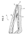
- FIG. 2 is a cross-sectional side view of a portion of a jet aircraft engine 10 including an oscillating jet 12, positioned according to another embodiment of the invention.
- FIG. 3 is a cross-sectional side view of a portion of a jet aircraft engine 10, similar to that shown in FIG. 1, where a flow control valve is located upstream of the oscillating jet 12.
- FIG. 4 shows an aircraft engine 10 with an oscillating jet 12 positioned in the exhaust portion 16 of the engine 10.
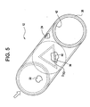
- FIG. 5 is an asymmetric, cross-sectional view of an oscillating jet 12, and
- FIG. 6 is a lateral cross-sectional view of an oscillating jet 12.
- the jet engine exhaust gas 14 passes through the engine exhaust portion 16 in a direction indicated by the arrow, past an aft lip 18 of the jet engine exhaust portion 16.
- a number of oscillating jets 12 are positioned on an external surface of the jet engine exhaust portion 16 . It is noted that in FIGs 1, 2 and 3 only a single jet 12 is shown for simplicity.
- the oscillating jets 12 are positioned symmetrically along the perimeter of the lip 18 of the jet engine exhaust portion 16. Other embodiments include positioning the oscillating jets asymmetrically with respect to the exhaust portion 16. The oscillating jets 12 are positioned to enhance mixing at peak noise locations in the engine portion 16. Additionally, the number of oscillating jets 12 employed vary according to the design requirements and limitations of the engine 10. The oscillating jets 12 can also be deployed in clusters with two (2) or more arranged to provide optimal mixing enhancement.
- the oscillating jets 12 mounted on an exterior surface of the exhaust portion 16 are positioned at an angle in the range of about 120 degrees to about 0 degrees with respect to the flow direction of the exhaust gases 14. In one embodiment, the oscillating jets are positioned at an angle of about 30 degrees with respect to the flow direction of the exhaust gases 14. The angle chosen for the oscillating jets 12 optimizes mixing of the oscillating flow, exiting from the oscillating jets 12, with the engine exhaust gases 14 and shear layers to create a fluidic chevron.
- Coupled to the oscillating jets 12 are channels 20 which direct the high pressure gas to the oscillating jets 12.
- the high pressure gas is air.
- Other embodiments could include air seeded with other non-combustible or combustible materials (liquids and solids).
- the high pressure gas needed to power, or flow through, the oscillating jets 12 is extracted from turbomachinery components positioned upstream from the engine exhaust portion 16, in the engine 10.
- high pressure gas can be provided by dedicated equipment employed for this purpose, if necessary.
- the pressure of the high pressure gas is in the range of about 5 to about 500 PSI. In one embodiment, the pressure of the high pressure gas is about 50 PSI.
- the pressure of the high pressure gas is selected to ensure sustained oscillation of the gas flow as it exits the oscillating jets 12, to provide mixing with the engine exhaust gases 14.
- FIG. 2 a portion of an aircraft engine 10 is shown having an oscillating jet 12 positioned within the aft lip 18 of the engine exhaust portion 16.
- the channels 20 for the oscillating jets 12 are positioned within the structure of the exhaust portion 16.
- the exit opening of the oscillating jet 12 is positioned such that the oscillating gas contacts, or begins mixing with, the engine exhaust gas 14 at a point aft of the aft lip 18 of the engine exhaust portion 16.
- the exit opening of the oscillating jet 12 is positioned upstream of the lip 18, such that the oscillating gas begins mixing with the exhaust gases 14 prior to the gases 14 exiting the engine 10. This is shown in FIG. 4.
- a combination of the above positioning is used, where some of the oscillating jets 12 are located such that the oscillating gas mixes with the engine exhaust gases 14 aft of the engine lip 18, while other oscillating jets 12 are located such that they exhaust the oscillating gas forward of the engine lip 18.
- FIG. 3 depicts a portion of an engine 10 similar to that shown in FIG.1.
- a flow control valve 28 is positioned to control the flow of high pressure gas in the channel 20 to the oscillating jet 12.
- the flow control valve 28 controls any one of the flow pressure, flow rate, flow volume, or any combination thereof. This provides a diversity of control regarding the flow of the oscillating gas exiting from the oscillating jet 12, including permitting the flow to be stopped, if desired.
- the operation of the flow control valve 28 is manual or automatic, or both depending on the design requirements and specifications.
- FIG. 4 shows an aircraft engine 10 with a number of oscillating jets 12 positioned on an outer surface of the exhaust portion 16 of the engine 10.
- the oscillating jets 12 are coupled to their respective channels 20.
- the upper channel 20 is coupled to a compressor stage 30, so as to provide high pressure air to the oscillating jet 12 from this stage of the engine 10.
- the lower channel 20 is coupled to a turbine stage 34, so as to provide high pressure air to the oscillating jet 12 from this stage of the engine 10.
- the lower oscillating jet 12 is positioned such that the oscillating gas mixes with the engine exhaust 14 upstream of the lip 18.
- both of the channels 20 are coupled to the same stage of the engine 10, so as to obtain the high pressure gas from the same engine stage.
- the oscillating jets 12 are positioned in the exhaust portion 16 of the engine 10 at the same location, so as to have the oscillating streams from the jets 12 mix with the engine exhaust gases 14 at the same plane in the engine exhaust portion 16. Further, it is noted that although only two oscillating jets 12 are depicted in FIG. 4, in another embodiment there are more than two oscillating jets.
- the channels 20 are coupled to a bypass air portion of the engine (not depicted). Further, in an additional embodiment all of the oscillating jets 12 are coupled to the same source of high pressure gas through a single channel 20.
- a flow control valve 28 is provided to control the flow of high pressure gas to the oscillating jets 12. Additionally, in each of the channels 20 a flow stabilizer 32 is located to stabilize the high pressure gas and aid in providing a uniform flow to the oscillating jets 12. In an embodiment, the flow stabilizers 32 are removed. In another embodiment, the flow stabilizers 32 are located upstream from the flow control valves 28.
- a combustor or heat source 46 is located upstream of the oscillating jets 12 to increase the pressure and temperature of the gas prior to entering the oscillating jets 12.
- a liquid spray is introduced into the gas prior to the gas exiting the jet 12.
- the liquid is water.
- other liquids, including a combustible liquid are used.
- the primary purpose of introducing these liquid sprays is to modify the mixing and oscillatory characteristics of the oscillating flow, such that they improve the mixing enhancement of the jet flow.
- a combustible liquid can be used to provide additional thrust for the engine. As the gas and combustible liquid mixture exits the oscillating jets 12, the liquid comes in contact with the engine exhaust and is ignited.
- the additional liquid can be added to the gas upstream of the jet 12 or within the structure of the jet 12. The addition of the liquid to the gas flowing through the nozzle 12 is to be such that the oscillation of the gas exiting the nozzle is not to be eliminated.
- fine solid particles are added to the flow of gas.
- the solid particles are made of a solid propellant material and are injected into the gas flow either within the oscillating jet 12 or upstream of the jet 12. The size and amount of particles added to the gas flow is such that the oscillating flow of the gas as it exits the oscillating jet is not eliminated.
- FIGs. 5 and 6 show an oscillating jet 12 having a nozzle 22 with a triangular shaped orifice 36 coupled to a cylindrically shaped exhaust pipe 24, from which the oscillating gas 26 exits.
- the triangular shaped orifice 36 is an equilateral triangle.
- a lip 38 is provided at the exit portion of the exhaust pipe 24, having a smaller diameter opening D L than the diameter D E of the inner surface of the exhaust pipe 24.
- the opening in the lip 38 is circular and has a chamfered edge 44.
- the triangular orifice 36 has a chamfered surface 40, to aid the flow of high pressure gas in separating at the upstream face of the orifice 36.
- the diameter D L of the opening in the lip 38 is the same as the diameter D E of the inner surface exhaust pipe 24. In another embodiment, the diameter D L of the lip 38 is about 90% of the diameter D E of the exhaust pipe 24. Also, in an embodiment of the invention, the chamfer 40 of the triangular orifice is rounded, made square or beveled to optimize flow separation and to control instabilities.
- the triangular orifice 36 has an effective diameter D TO , which is equivalent to a diameter of a circle having the same area as the orifice 36.
- the nozzle 22 has an internal diameter D N
- the exhaust pipe 24 has a length L from the upstream surface of the orifice 36 to the downstream surface of the lip 38.
- the ratio of the exhaust pipe diameter D E to the effective diameter D TO of the orifice is in the range of about two (2) to about five (5).
- the ratio of the length L of the exhaust pipe 24 to the diameter D E of the pipe 24 is in the range of about 1.5 to about four (4). Each of these ratios is optimized with respect to the operational parameters of the oscillating jets 12.
- the high pressure gas from the channel 20 passes through the nozzle 22 and the triangular orifice 36 and enters the exhaust pipe 24.
- the length L and diameter D E of exhaust pipe 24 are selected to optimize the oscillation of the oscillating gas 26.
- the nozzle 22, triangular orifice 36, exhaust pipe 24 and channel 20 are made from typical materials used in jet aircraft engines. According to a particular embodiment, the materials are optimized based on the operating conditions and environment of the jets 12. Further, these components are secured to each via welding, fasteners or other suitable methods capable of withstanding the engine 10 operating parameters and pressures. In one embodiment, at least the nozzle 22, orifice 36 and the cylinder 24 are made integrally with each other.
- the triangular orifice 36 is variable to provide optimization of oscillating flow at various stages and under various flight parameters.
- the length L of the exhaust pipe 24 is adjustable to provide optimization of oscillating flow at various stages and under various flight parameters. In either embodiment, the variations or adjustments are made either manually or automatically to optimize the oscillating flow at various conditions.
Landscapes
- Engineering & Computer Science (AREA)
- Chemical & Material Sciences (AREA)
- Combustion & Propulsion (AREA)
- Mechanical Engineering (AREA)
- General Engineering & Computer Science (AREA)
- Exhaust Silencers (AREA)
- Jet Pumps And Other Pumps (AREA)
Applications Claiming Priority (2)
| Application Number | Priority Date | Filing Date | Title |
|---|---|---|---|
| US10/750,240 US7308966B2 (en) | 2003-12-30 | 2003-12-30 | Device for reducing jet engine exhaust noise using oscillating jets |
| US750240 | 2003-12-30 |
Publications (2)
| Publication Number | Publication Date |
|---|---|
| EP1553281A1 true EP1553281A1 (de) | 2005-07-13 |
| EP1553281B1 EP1553281B1 (de) | 2008-06-11 |
Family
ID=34592544
Family Applications (1)
| Application Number | Title | Priority Date | Filing Date |
|---|---|---|---|
| EP04257993A Not-in-force EP1553281B1 (de) | 2003-12-30 | 2004-12-21 | Vorrichtung zur Reduktion des Austrittslärms von Strahltriebwerken unter Benutzung von oszillierenden Strahlen |
Country Status (5)
| Country | Link |
|---|---|
| US (1) | US7308966B2 (de) |
| EP (1) | EP1553281B1 (de) |
| JP (1) | JP4613061B2 (de) |
| CN (1) | CN1637262A (de) |
| DE (1) | DE602004014337D1 (de) |
Families Citing this family (21)
| Publication number | Priority date | Publication date | Assignee | Title |
|---|---|---|---|---|
| FR2892152B1 (fr) * | 2005-10-19 | 2007-11-23 | Airbus France Sas | Turbomoteur a bruit de jet attenue |
| US8015819B2 (en) * | 2006-09-29 | 2011-09-13 | The United States Of America As Represented By The Administrator Of The National Aeronautics And Space Administration | Wet active chevron nozzle for controllable jet noise reduction |
| FR2928183A1 (fr) * | 2008-02-29 | 2009-09-04 | Aircelle Sa | Dispositif de reduction de bruit pour moteur d'aeronef, du type a chevrons mobiles |
| FR2929337B1 (fr) * | 2008-03-31 | 2012-06-01 | Airbus France | Dispositif a jets secondaires de reduction du bruit genere par un reacteur d'aeronef |
| JP5360835B2 (ja) * | 2008-07-28 | 2013-12-04 | 国立大学法人群馬大学 | 噴流騒音防止方法および噴流ノズル |
| JP5459317B2 (ja) * | 2009-10-28 | 2014-04-02 | 株式会社Ihi | 騒音低減装置 |
| US9528468B2 (en) * | 2009-10-28 | 2016-12-27 | Ihi Corporation | Noise reduction system |
| EP2397762A1 (de) * | 2010-06-17 | 2011-12-21 | Siemens Aktiengesellschaft | Dämpfvorrichtung zum Dämpfen von Druckschwingungen in einer Brennkammer einer Turbine |
| US8443931B2 (en) | 2011-04-06 | 2013-05-21 | Lockheed Martin Corporation | Noise reduction of supersonic jet engines |
| US8984714B2 (en) | 2011-10-04 | 2015-03-24 | Bha Altair, Llc | Method and systems for acoustic cleaning |
| CN103101614B (zh) * | 2011-11-14 | 2015-05-06 | 中国航空工业集团公司沈阳空气动力研究所 | 一种定常微射流武器舱噪声抑制装置 |
| DE102012109647B4 (de) * | 2012-10-10 | 2015-09-03 | Airbus Defence and Space GmbH | Flugtriebwerk mit einer Einrichtung zum pulsierenden Ausblasen eines Gases in die Abgasdüse |
| US9428263B2 (en) * | 2013-10-16 | 2016-08-30 | The Boeing Company | Frequency response and health tracker for a synthetic jet generator |
| US9869190B2 (en) | 2014-05-30 | 2018-01-16 | General Electric Company | Variable-pitch rotor with remote counterweights |
| US10072510B2 (en) | 2014-11-21 | 2018-09-11 | General Electric Company | Variable pitch fan for gas turbine engine and method of assembling the same |
| FR3041596B1 (fr) * | 2015-09-30 | 2017-12-08 | Plastic Omnium Cie | Systeme aerodynamique a generateur de vortex alimente par des gaz d'echappement |
| US10100653B2 (en) | 2015-10-08 | 2018-10-16 | General Electric Company | Variable pitch fan blade retention system |
| CN107023420B (zh) * | 2017-05-16 | 2018-09-21 | 北京理工大学 | 一种具有推力可控功能的二次流喉栓火箭发动机 |
| CN106988928B (zh) * | 2017-05-16 | 2019-05-07 | 北京理工大学 | 一种具有抗烧蚀和降温功能的二次流喉栓火箭发动机 |
| US11674435B2 (en) | 2021-06-29 | 2023-06-13 | General Electric Company | Levered counterweight feathering system |
| US11795964B2 (en) | 2021-07-16 | 2023-10-24 | General Electric Company | Levered counterweight feathering system |
Citations (6)
| Publication number | Priority date | Publication date | Assignee | Title |
|---|---|---|---|---|
| US5092425A (en) * | 1990-04-02 | 1992-03-03 | The United States Of America As Represented By The Secretary Of The Air Force | Jet noise suppressor and method |
| WO1999026021A1 (en) * | 1997-11-18 | 1999-05-27 | Luminis Pty. Ltd. | Oscillating jets |
| US6308898B1 (en) * | 1999-06-11 | 2001-10-30 | The Boeing Company | Apparatus and methods for active flow control of a nozzle exhaust plume |
| US6571549B1 (en) * | 2001-10-05 | 2003-06-03 | The United States Of America As Represented By The Secretary Of The Air Force | Jet noise suppressor |
| EP1418331A2 (de) * | 2002-11-09 | 2004-05-12 | ROLLS-ROYCE plc | Abgasschalldämpfer für Gasturbinen |
| EP1493912A1 (de) * | 2003-06-30 | 2005-01-05 | General Electric Company | Fluidisches Abströmelement und konfigurierbarer thermischer Schield zur Reduktion von Luftstrahllärm |
Family Cites Families (19)
| Publication number | Priority date | Publication date | Assignee | Title |
|---|---|---|---|---|
| US2943821A (en) * | 1950-12-30 | 1960-07-05 | United Aircraft Corp | Directional control means for a supersonic vehicle |
| FR1370149A (fr) * | 1963-07-11 | 1964-08-21 | Snecma | Déviateur de jet par injection de liquide |
| US3204405A (en) * | 1964-02-20 | 1965-09-07 | Raymond W Warren | Three dimensional jet vectoring system |
| US3420060A (en) * | 1966-04-22 | 1969-01-07 | Mc Donnell Douglas Corp | Pressure induced jet vectoring augmentation apparatus |
| US3527317A (en) * | 1969-04-18 | 1970-09-08 | Gen Electric | Sound control of turbofan engines |
| US3826331A (en) * | 1972-02-29 | 1974-07-30 | Bolt Beranek & Newman | Method of and apparatus for reducing sound generated by surfaces in fluid jet streams and the like |
| US3830431A (en) * | 1973-03-23 | 1974-08-20 | Nasa | Abating exhaust noises in jet engines |
| US4474259A (en) * | 1982-04-26 | 1984-10-02 | The Boeing Company | Internally ventilated noise suppressor for jet engine |
| US5428954A (en) * | 1994-04-11 | 1995-07-04 | Cowan, Sr.; Howard H. | System for suppressing engine exhaust noise |
| US5664415A (en) * | 1994-06-01 | 1997-09-09 | Lockheed Fort Worth Company | After-burning turbo-fan engine with a fixed geometry exhaust nozzle having a variable flow coefficient |
| US5490545A (en) * | 1994-08-31 | 1996-02-13 | Michael D. Sokoloff | Vortex connector |
| US5590520A (en) * | 1995-05-05 | 1997-01-07 | The Regents Of The University Of California | Method of eliminating mach waves from supersonic jets |
| US5758823A (en) * | 1995-06-12 | 1998-06-02 | Georgia Tech Research Corporation | Synthetic jet actuator and applications thereof |
| US6336319B1 (en) * | 2000-05-26 | 2002-01-08 | General Electric Company | Fluidic nozzle control system |
| US6308740B1 (en) * | 2000-08-15 | 2001-10-30 | Lockheed Martin Corporation | Method and system of pulsed or unsteady ejector |
| US6375118B1 (en) * | 2000-08-30 | 2002-04-23 | The Boeing Company | High frequency excitation apparatus and method for reducing jet and cavity noise |
| US6532729B2 (en) * | 2001-05-31 | 2003-03-18 | General Electric Company | Shelf truncated chevron exhaust nozzle for reduction of exhaust noise and infrared (IR) signature |
| US6655632B1 (en) * | 2002-08-27 | 2003-12-02 | General Electric Company | System and method for actively changing an effective flow-through area of an inlet region of an aircraft engine |
| US7086498B2 (en) * | 2003-08-25 | 2006-08-08 | Ford Global Technologies, Llc | Noise attenuation device for a vehicle exhaust system |
-
2003
- 2003-12-30 US US10/750,240 patent/US7308966B2/en active Active
-
2004
- 2004-12-21 DE DE602004014337T patent/DE602004014337D1/de active Active
- 2004-12-21 EP EP04257993A patent/EP1553281B1/de not_active Not-in-force
- 2004-12-28 JP JP2004380330A patent/JP4613061B2/ja not_active Expired - Fee Related
- 2004-12-30 CN CNA2004100821902A patent/CN1637262A/zh active Pending
Patent Citations (6)
| Publication number | Priority date | Publication date | Assignee | Title |
|---|---|---|---|---|
| US5092425A (en) * | 1990-04-02 | 1992-03-03 | The United States Of America As Represented By The Secretary Of The Air Force | Jet noise suppressor and method |
| WO1999026021A1 (en) * | 1997-11-18 | 1999-05-27 | Luminis Pty. Ltd. | Oscillating jets |
| US6308898B1 (en) * | 1999-06-11 | 2001-10-30 | The Boeing Company | Apparatus and methods for active flow control of a nozzle exhaust plume |
| US6571549B1 (en) * | 2001-10-05 | 2003-06-03 | The United States Of America As Represented By The Secretary Of The Air Force | Jet noise suppressor |
| EP1418331A2 (de) * | 2002-11-09 | 2004-05-12 | ROLLS-ROYCE plc | Abgasschalldämpfer für Gasturbinen |
| EP1493912A1 (de) * | 2003-06-30 | 2005-01-05 | General Electric Company | Fluidisches Abströmelement und konfigurierbarer thermischer Schield zur Reduktion von Luftstrahllärm |
Also Published As
| Publication number | Publication date |
|---|---|
| CN1637262A (zh) | 2005-07-13 |
| JP4613061B2 (ja) | 2011-01-12 |
| EP1553281B1 (de) | 2008-06-11 |
| JP2005195019A (ja) | 2005-07-21 |
| US7308966B2 (en) | 2007-12-18 |
| DE602004014337D1 (de) | 2008-07-24 |
| US20050144935A1 (en) | 2005-07-07 |
Similar Documents
| Publication | Publication Date | Title |
|---|---|---|
| EP1553281B1 (de) | Vorrichtung zur Reduktion des Austrittslärms von Strahltriebwerken unter Benutzung von oszillierenden Strahlen | |
| US7159383B2 (en) | Apparatus, method and system for gas turbine engine noise reduction | |
| US7055329B2 (en) | Method and apparatus for noise attenuation for gas turbine engines using at least one synthetic jet actuator for injecting air | |
| EP0700498B1 (de) | Radial angeordneter druckluftinjektor für kraftstoff | |
| US7600384B2 (en) | Gas exhaust nozzle for a bypass turbomachine having an exhaust or throat section that can be varied by moving the secondary cowl | |
| EP1580417B1 (de) | Verfahren und Gasturbine mit einem System zur Schalldämpfung | |
| CN103184913B (zh) | 紧凑式高压排气消音装置 | |
| US7614211B2 (en) | Swirling flows and swirler to enhance pulse detonation engine operation | |
| EP1881161A2 (de) | Abblaseventil eines Flugtriebwerks | |
| EP3163054A1 (de) | Verfahren und system zur abschwächung von hohlraumresonanzen | |
| EP1780124B1 (de) | Vorrichtung zur Auflösung von Verwirbelungen in einem Eduktor | |
| US4696159A (en) | Gas turbine outlet arrangement | |
| CN105637208A (zh) | 用于发动机的喷管安排 | |
| US10352570B2 (en) | Turbine engine fuel injection system and methods of assembling the same | |
| US10781756B2 (en) | Active tip clearance control system for gas turbine engine | |
| US7197881B2 (en) | Low loss flow limited feed duct | |
| EP2993405A1 (de) | Variabler öffnungsstrahl für einen turbinenmotor | |
| US9759133B2 (en) | Turbofan with variable bypass flow | |
| EP1036988A3 (de) | Kraftstoff/Luft-Vormischeinrichtung mit veränderlicher Geometrie und Methode, die Ausströmgeschwindigkeit zu regeln | |
| CN102597474A (zh) | 噪声降低装置 | |
| EP4220013A1 (de) | Brennstoffmischer für turbinenmotor | |
| US20220364511A1 (en) | Integral fuel-nozzle and mixer with angled jet-in-crossflow fuel injection | |
| US20090165864A1 (en) | Supersonic inlet | |
| MXPA97009841A (en) | Nozzle to supply liquid mixture / |
Legal Events
| Date | Code | Title | Description |
|---|---|---|---|
| PUAI | Public reference made under article 153(3) epc to a published international application that has entered the european phase |
Free format text: ORIGINAL CODE: 0009012 |
|
| AK | Designated contracting states |
Kind code of ref document: A1 Designated state(s): AT BE BG CH CY CZ DE DK EE ES FI FR GB GR HU IE IS IT LI LT LU MC NL PL PT RO SE SI SK TR |
|
| AX | Request for extension of the european patent |
Extension state: AL BA HR LV MK YU |
|
| 17P | Request for examination filed |
Effective date: 20060113 |
|
| AKX | Designation fees paid |
Designated state(s): DE FR GB |
|
| GRAP | Despatch of communication of intention to grant a patent |
Free format text: ORIGINAL CODE: EPIDOSNIGR1 |
|
| GRAS | Grant fee paid |
Free format text: ORIGINAL CODE: EPIDOSNIGR3 |
|
| GRAA | (expected) grant |
Free format text: ORIGINAL CODE: 0009210 |
|
| AK | Designated contracting states |
Kind code of ref document: B1 Designated state(s): DE FR GB |
|
| REG | Reference to a national code |
Ref country code: GB Ref legal event code: FG4D |
|
| REF | Corresponds to: |
Ref document number: 602004014337 Country of ref document: DE Date of ref document: 20080724 Kind code of ref document: P |
|
| PLBE | No opposition filed within time limit |
Free format text: ORIGINAL CODE: 0009261 |
|
| STAA | Information on the status of an ep patent application or granted ep patent |
Free format text: STATUS: NO OPPOSITION FILED WITHIN TIME LIMIT |
|
| 26N | No opposition filed |
Effective date: 20090312 |
|
| REG | Reference to a national code |
Ref country code: FR Ref legal event code: PLFP Year of fee payment: 12 |
|
| REG | Reference to a national code |
Ref country code: FR Ref legal event code: PLFP Year of fee payment: 13 |
|
| REG | Reference to a national code |
Ref country code: FR Ref legal event code: PLFP Year of fee payment: 14 |
|
| PGFP | Annual fee paid to national office [announced via postgrant information from national office to epo] |
Ref country code: DE Payment date: 20191119 Year of fee payment: 16 |
|
| PGFP | Annual fee paid to national office [announced via postgrant information from national office to epo] |
Ref country code: FR Payment date: 20191120 Year of fee payment: 16 |
|
| PGFP | Annual fee paid to national office [announced via postgrant information from national office to epo] |
Ref country code: GB Payment date: 20191122 Year of fee payment: 16 |
|
| REG | Reference to a national code |
Ref country code: DE Ref legal event code: R119 Ref document number: 602004014337 Country of ref document: DE |
|
| GBPC | Gb: european patent ceased through non-payment of renewal fee |
Effective date: 20201221 |
|
| PG25 | Lapsed in a contracting state [announced via postgrant information from national office to epo] |
Ref country code: FR Free format text: LAPSE BECAUSE OF NON-PAYMENT OF DUE FEES Effective date: 20201231 |
|
| PG25 | Lapsed in a contracting state [announced via postgrant information from national office to epo] |
Ref country code: GB Free format text: LAPSE BECAUSE OF NON-PAYMENT OF DUE FEES Effective date: 20201221 Ref country code: DE Free format text: LAPSE BECAUSE OF NON-PAYMENT OF DUE FEES Effective date: 20210701 |