EP1553244A1 - Scaffolding device for work on inner wall face of tower vessel body, and method of work on inner wall face using the scaffolding device - Google Patents
Scaffolding device for work on inner wall face of tower vessel body, and method of work on inner wall face using the scaffolding device Download PDFInfo
- Publication number
- EP1553244A1 EP1553244A1 EP03730815A EP03730815A EP1553244A1 EP 1553244 A1 EP1553244 A1 EP 1553244A1 EP 03730815 A EP03730815 A EP 03730815A EP 03730815 A EP03730815 A EP 03730815A EP 1553244 A1 EP1553244 A1 EP 1553244A1
- Authority
- EP
- European Patent Office
- Prior art keywords
- operations
- tower structure
- posts
- wall surface
- height adjustable
- Prior art date
- Legal status (The legal status is an assumption and is not a legal conclusion. Google has not performed a legal analysis and makes no representation as to the accuracy of the status listed.)
- Withdrawn
Links
- 238000000034 method Methods 0.000 title claims description 12
- 239000000463 material Substances 0.000 claims description 24
- 230000009467 reduction Effects 0.000 abstract description 7
- 238000004140 cleaning Methods 0.000 description 16
- CURLTUGMZLYLDI-UHFFFAOYSA-N Carbon dioxide Chemical compound O=C=O CURLTUGMZLYLDI-UHFFFAOYSA-N 0.000 description 11
- 238000010276 construction Methods 0.000 description 11
- 230000000694 effects Effects 0.000 description 9
- 230000006872 improvement Effects 0.000 description 6
- 238000009434 installation Methods 0.000 description 5
- 230000008439 repair process Effects 0.000 description 5
- 238000005422 blasting Methods 0.000 description 4
- 238000004519 manufacturing process Methods 0.000 description 4
- 238000009423 ventilation Methods 0.000 description 4
- 238000003466 welding Methods 0.000 description 4
- 238000007689 inspection Methods 0.000 description 3
- 238000005304 joining Methods 0.000 description 3
- 230000009471 action Effects 0.000 description 2
- 235000011089 carbon dioxide Nutrition 0.000 description 2
- 238000006073 displacement reaction Methods 0.000 description 2
- 239000010419 fine particle Substances 0.000 description 2
- 238000009408 flooring Methods 0.000 description 2
- 238000012423 maintenance Methods 0.000 description 2
- 230000004048 modification Effects 0.000 description 2
- 238000012986 modification Methods 0.000 description 2
- 238000005096 rolling process Methods 0.000 description 2
- 235000017166 Bambusa arundinacea Nutrition 0.000 description 1
- 235000017491 Bambusa tulda Nutrition 0.000 description 1
- 241001330002 Bambuseae Species 0.000 description 1
- 235000015334 Phyllostachys viridis Nutrition 0.000 description 1
- 229910000831 Steel Inorganic materials 0.000 description 1
- 238000005299 abrasion Methods 0.000 description 1
- 230000001464 adherent effect Effects 0.000 description 1
- 239000011425 bamboo Substances 0.000 description 1
- 238000006243 chemical reaction Methods 0.000 description 1
- 238000005336 cracking Methods 0.000 description 1
- 230000002349 favourable effect Effects 0.000 description 1
- 230000005484 gravity Effects 0.000 description 1
- 230000036541 health Effects 0.000 description 1
- JEIPFZHSYJVQDO-UHFFFAOYSA-N iron(III) oxide Inorganic materials O=[Fe]O[Fe]=O JEIPFZHSYJVQDO-UHFFFAOYSA-N 0.000 description 1
- 230000014759 maintenance of location Effects 0.000 description 1
- 238000011017 operating method Methods 0.000 description 1
- 230000001105 regulatory effect Effects 0.000 description 1
- 230000000717 retained effect Effects 0.000 description 1
- 239000010959 steel Substances 0.000 description 1
- 238000003860 storage Methods 0.000 description 1
- 239000000126 substance Substances 0.000 description 1
- 238000012546 transfer Methods 0.000 description 1
- 238000005493 welding type Methods 0.000 description 1
Images




Classifications
-
- E—FIXED CONSTRUCTIONS
- E04—BUILDING
- E04G—SCAFFOLDING; FORMS; SHUTTERING; BUILDING IMPLEMENTS OR AIDS, OR THEIR USE; HANDLING BUILDING MATERIALS ON THE SITE; REPAIRING, BREAKING-UP OR OTHER WORK ON EXISTING BUILDINGS
- E04G1/00—Scaffolds primarily resting on the ground
- E04G1/36—Scaffolds for particular parts of buildings or buildings of particular shape, e.g. for stairs, cupolas, domes
-
- E—FIXED CONSTRUCTIONS
- E04—BUILDING
- E04G—SCAFFOLDING; FORMS; SHUTTERING; BUILDING IMPLEMENTS OR AIDS, OR THEIR USE; HANDLING BUILDING MATERIALS ON THE SITE; REPAIRING, BREAKING-UP OR OTHER WORK ON EXISTING BUILDINGS
- E04G1/00—Scaffolds primarily resting on the ground
- E04G1/18—Scaffolds primarily resting on the ground adjustable in height
- E04G1/20—Scaffolds comprising upright members and provision for supporting cross-members or platforms at different positions therealong
-
- E—FIXED CONSTRUCTIONS
- E04—BUILDING
- E04G—SCAFFOLDING; FORMS; SHUTTERING; BUILDING IMPLEMENTS OR AIDS, OR THEIR USE; HANDLING BUILDING MATERIALS ON THE SITE; REPAIRING, BREAKING-UP OR OTHER WORK ON EXISTING BUILDINGS
- E04G1/00—Scaffolds primarily resting on the ground
- E04G1/36—Scaffolds for particular parts of buildings or buildings of particular shape, e.g. for stairs, cupolas, domes
- E04G1/362—Scaffolds for particular parts of buildings or buildings of particular shape, e.g. for stairs, cupolas, domes specially adapted for tanks, silos or similar vessels
-
- E—FIXED CONSTRUCTIONS
- E04—BUILDING
- E04G—SCAFFOLDING; FORMS; SHUTTERING; BUILDING IMPLEMENTS OR AIDS, OR THEIR USE; HANDLING BUILDING MATERIALS ON THE SITE; REPAIRING, BREAKING-UP OR OTHER WORK ON EXISTING BUILDINGS
- E04G3/00—Scaffolds essentially supported by building constructions, e.g. adjustable in height
- E04G3/24—Scaffolds essentially supported by building constructions, e.g. adjustable in height specially adapted for particular parts of buildings or for buildings of particular shape, e.g. chimney stacks or pylons
-
- E—FIXED CONSTRUCTIONS
- E04—BUILDING
- E04G—SCAFFOLDING; FORMS; SHUTTERING; BUILDING IMPLEMENTS OR AIDS, OR THEIR USE; HANDLING BUILDING MATERIALS ON THE SITE; REPAIRING, BREAKING-UP OR OTHER WORK ON EXISTING BUILDINGS
- E04G3/00—Scaffolds essentially supported by building constructions, e.g. adjustable in height
- E04G3/24—Scaffolds essentially supported by building constructions, e.g. adjustable in height specially adapted for particular parts of buildings or for buildings of particular shape, e.g. chimney stacks or pylons
- E04G3/246—Scaffolds essentially supported by building constructions, e.g. adjustable in height specially adapted for particular parts of buildings or for buildings of particular shape, e.g. chimney stacks or pylons following the inside contour of a building
Definitions
- the present invention relates to a scaffold apparatus for conducting operations on an inner wall surface of a tower structure, used for conducting a variety of operations on the inner wall surface of a tall tower structure with a blast furnace type structure, such as the digester provided in a paper production plant, as well as an operational method for an inner wall surface using such a scaffold apparatus.
- maintenance is essential in ensuring retention of the tower functions over an extended period, and the inner wall surface of the tower in particular is exposed to severe temperature and pressure conditions, or a corrosive environment of chemicals or the like, and consequently frequent maintenance operations such as inspections, cleaning, modifications and welding must be undertaken.
- a tower structure is tall, and the operational target zone extends over a wide height range, from regions near the bottom of the tower to regions near the top, and because the operations on the inner wall surface of such a tower structure require both operators and a variety of operational materials, an operations scaffold must be put up inside the tower structure.
- the most typical method of assembling this type of operations scaffold has usually involved assembling a scaffold framework inside the tower, and then providing an operations footing on top.
- an object of the present invention is to provide a scaffold apparatus for conducting operations on an inner wall surface of a tower structure, which enables operations on the inner wall surface of the tower structure to be conducted safely and with good operability, as well as an operational method that utilizes such a scaffold apparatus.
- a scaffold apparatus for conducting operations on an inner wall surface of a tower structure comprises either a single post or a plurality of posts put up inside a tower structure from a bottom section thereof toward a top section, and a height adjustable operations platform that is attached to the posts in a manner of freely movable in up or down direction.
- a scaffold apparatus for conducting operations on an inner wall surface of a tower structure comprises either a single post or a plurality of posts put up inside a tower structure from a bottom section thereof toward a top section, and a height adjustable operations platform that is attached to the posts in a manner of freely movable in up or down direction, and consequently, putting up the posts inside the tower structure and then attaching the height adjustable operations platform means that when any of a variety of operations are conducted on the inner wall surface of the tower structure, adjustments of the installation height of the height adjustable operations platform within the tower structure (that is, the height position at which operations are conducted using the height adjustable operations platform) are performed easily and quickly by moving the height adjustable operations platform up or down along the posts.
- a second aspect of the present invention is the scaffold apparatus for conducting operations on an inner wall surface of a tower structure according to the first aspect of the present invention, wherein the posts are put up by sequentially stacking and connecting a plurality of posts pieces, which are of dimensions that enable transport through a materials transport port provided in the tower structure, from the bottom section of the tower structure toward the top section.
- a scaffold apparatus for conducting operations on an inner wall surface of a tower structure according to this second aspect of the present invention offers the following characteristic effects in addition to the effects provided by the first aspect of the invention.
- the posts are put up by sequentially stacking and connecting a plurality of posts pieces, which are of dimensions that enable transport through a materials transport port provided in the tower structure, from the bottom section of the tower structure toward the top section, and consequently, even though the operation must be conducted under the restricted operational space conditions unique to tower structures, a post of any height is put up easily by carrying the required number of post pieces into the tower structure and then sequentially combining the pieces.
- the scaffold apparatus is applied to inner wall surface operations within a variety of different tower structures of different heights, enabling an improvement in the general-purpose applicability of the scaffold apparatus.
- a third aspect of the present invention is the scaffold apparatus for conducting operations on an inner wall surface of a tower structure according to either of the first or second aspects of the present invention, wherein the bottom end of each post is supported by a lower support base, which is secured immediately above a tower bottom section via securing pieces provided on the side wall of the tower structure immediately above the tower bottom section.
- a scaffold apparatus for conducting operations on an inner wall surface of a tower structure according to this third aspect of the present invention offers the following characteristic effects in addition to the effects provided by the first and second aspects of the invention. Namely, in the scaffold apparatus for conducting operations on an inner wall surface of a tower structure according to this aspect of the present invention, the bottom end of each post is supported by a lower support base secured immediately above a tower bottom section via a securing piece provided on the side wall of the tower structure immediately above the tower bottom section, and consequently the entire weight, including the dead load of the posts and the attached height adjustable operations platform, and the weight of any operators and/or operating materials loaded onto this height adjustable operations platform, is supported directly by the side walls at a point immediately above the tower bottom section of the tower structure, via the aforementioned lower support base, and the application of load onto the tower bottom section is avoided.
- the weight of the posts and the like is supported more reliably and in a more stable manner, and both the reliability of the installation of the posts and the like, and the reliability of the various operations conducted using the posts and the attached height adjustable operations platform, are improved.
- the tower bottom section of the tower structure has the end plate structure described above, that section is more complex and more expensive to produce than the side wall section, and consequently by not needing to use this tower bottom section as the support site for the posts and the like, damage to the tower bottom section is effectively avoided, resulting in an improvement of the durability of the tower structure, or a reduction of the production costs.
- a fourth aspect of the present invention is the scaffold apparatus for conducting operations on an inner wall surface of a tower structure according to the first aspect of the present invention, wherein the height adjustable operations platform is a knockdown structure that is capable of being transported through a materials transport port provided in the tower structure.
- a scaffold apparatus for conducting operations on an inner wall surface of a tower structure according to this fourth aspect of the present invention offers the following characteristic effects in addition to the effects provided by the first aspect of the invention.
- the height adjustable operations platform is a knockdown structure that is capable of being transported through a materials transport port provided in the tower structure, and consequently even though the operation must be conducted under the restricted operational space conditions unique to tower structures, a height adjustable operations platform having any of a variety of different shapes (namely, a shape that corresponds with the internal dimensions of the target tower structure) is assembled easily by carrying the disassembled members into the tower structure and then sequentially combining the members, and as a result, the scaffold apparatus become applied to inner wall surface operations within a variety of different tower structures of different internal dimensions, enabling an improvement in the general purpose applicability of the scaffold apparatus.
- a fifth aspect of the present invention is the scaffold apparatus for conducting operations on an inner wall surface of a tower structure according to the fourth aspect of the present invention, wherein the height adjustable operations platform is equipped with elevation drive means that enables the platform to be raised and lowered under its own power, and the external periphery of the height adjustable operations platform is equipped with guide wheel units that are provided with a wheel, which displaces freely toward, and away from, the inner wall surface of the tower structure and is held in continuous contact with the inner wall surface by a predetermined pressure.
- a scaffold apparatus for conducting operations on an inner wall surface of a tower structure according to this fifth aspect of the present invention offers the following characteristic effects in addition to the effects provided by the fourth aspect of the invention.
- the height adjustable operations platform is equipped with elevation drive means that enables the platform to be raised and lowered under its own power
- the external periphery of the height adjustable operations platform is equipped with guide wheel units that are provided with a wheel, which displaces freely toward, and away from, the inner wall surface of the tower structure and is held in continuous contact with the inner wall surface by a predetermined pressure.
- the height adjustable operations platform is capable of being raised and lowered under its own power, during various operations using the height adjustable operations platform, adjustments to the height of the height adjustable operations platform is performed easily and quickly, for example in accordance with the requirements of an operator, and consequently both the operability and mobility are good, meaning the operating efficiency of operations that are conducted using the height adjustable operations platform is improved markedly.
- an operational method for an inner wall surface comprises the steps of loading people and/or an operating material onto a height adjustable operations platform, which is attached to a single post or a plurality of posts put up inside a tower structure from a bottom section thereof toward a top section in a manner that enables free up or down movement along the posts, and adjusting the operating height by moving the height adjustable operations platform up and down along the posts, while performing the required operations on the inner wall surface of the tower structure.
- an operational method for an inner wall surfaces of a tower structure by using this type of operational method, in an operational method for an inner wall surfaces of a tower structure according to the sixth aspect of the present invention, people and/or operating materials are loaded onto a height adjustable operations platform, which is attached to a single post or a plurality of posts put up inside a tower structure from a bottom section thereof toward a top section in a manner that enables free up or down movement along the posts, and the operating height is adjusted by moving the height adjustable operations platform up and down along the posts, while the required operations are performed on the inner wall surfaces of the tower structure, and consequently, compared with a conventional case in which, for example, a level adjustment operation such as adding to the scaffold framework is required inside the tower structure every time the operating height is altered, the operating efficiency of inner wall surface operations improves markedly, and because level adjustment operations need not be conducted at great heights, the safety of the operations also improves, meaning operations realizes both cost reductions and improvement of safety.
- a level adjustment operation such as adding to the scaffold framework is required
- FIG. 1 shows a digester 1, with a scaffold apparatus for operations, which is used for conducting a cleaning operation of the inner wall surface, erected therein.
- the digester 1 is, for example, a large scale, tall, closed vessel with an internal diameter of 4 to 5 meters and a height of 40 to 50 meters, and is classified as a type-1 pressure vessel in the safety standards. Accordingly, the state of the inner wall surface must be inspected for safety purposes, and where necessary, required inner wall surface repair operations, such as the repair, by welding, of reduced thickness sections caused by cracking or abrasion of the inner wall surface, must be carried out. When this type of welding repair of the inner wall surface is required, the inner wall surface must first be subjected to a cleaning operation as a preparatory operation. In this embodiment, a cleaning operation using a CO 2 blast device, which acts as a preparatory operation for a welding repair operation, is described as an example of an operation that uses the scaffold apparatus for operations.
- the digester 1 is formed as a sealed vessel, comprising a main body section 2 with a large diameter cylindrical structure, and a digester bottom structure 3 with an end plate construction joined at the bottom end and a digester top structure 4 joined at the top end, and is fixed in a vertical position with a bottom section 1a of the digester bottom structure 3 supported on a base 5.
- the main body section 2 has a so-called “bamboo construction" wherein the diameter dimension reduces in a stepwise manner from the bottom section 1a of the digester 1 through to a top section 1b, and comprises a first main body section 21 that has the largest diameter and is joined to the top edge of the digester bottom structure 3, a second main body section 22, which is of a smaller diameter than the first main body section 21 and is joined so that the bottom end thereof is inserted inside the top end of the first main body section 21, and a third main body section 23, which is of a smaller diameter than the second main body section 22, is joined so that the bottom end thereof is inserted inside the top end of the second main body section 22, and which has the aforementioned digester top structure 4 joined to the top end thereof.
- a second main body section 22 which is of a smaller diameter than the first main body section 21 and is joined so that the bottom end thereof is inserted inside the top end of the first main body section 21, and a third main body section 23, which is of a smaller diameter than the second main body section 22, is
- an inner wall surface 1d of the main body section 2 has a stepped structure in which the internal diameter dimension varies at the joint regions between the first main body section 21 through the third main body section 23. Consequently, a height adjustable operations platform 8 described below, which is used during cleaning operations of the inner wall surface 1d, has a structure that enables vertical movement from the first main body section 21 through to the third main body section 23 without being affected in any way by the steps at the joint sections between the main body sections.
- the CO 2 blasting is a technique in which fine particles of dry ice are projected at the target surface as a blast material, and during the blasting operation, because CO 2 gas accumulates at the bottom inside the digester 1, in order to generate a downward ventilation flow inside the digester 1, an exhaust system 32 is attached to a bottom manhole 31 provided in a central position within the digester bottom structure 3, exhaust systems 33, 34 are disposed at a pair of upper and lower manholes provided toward the top section 1b, and an air supply device 37 is provided at a large diameter manhole 35 provided substantially halfway up the digester.
- This ventilation system ensures a good working environment inside the digester 1, and guarantees a highly safe operation.
- a manhole 36 provided near the joint section between the digester bottom structure 3 and the first main body section 21 of the digester 1 is used for carrying materials in and out of the digester 1, and for people to enter or exit from the digester 1.
- the aforementioned scaffold apparatus for operations comprises a left and right pair of posts 16, which are put up from the bottom section 1a of the digester 1 toward the top section 1b, and the bottom ends of which are supported by a lower fixed operations floor 6 and the top ends of which are supported by an upper fixed operations floor 7, and a height adjustable operations platform 8 which moves up and down along each of these posts 16.
- the aforementioned lower fixed operations floor 6, the upper fixed operations floor 7, the height adjustable operations platform 8, and the posts 16 that make up the scaffold apparatus for operations are all divided structures, and are each carried into the digester 1 in a disassembled state through the manhole 36, and then assembled inside the digester 1.
- the aforementioned lower fixed operations floor 6, the upper fixed operations floor 7, the height adjustable operations platform 8, and the posts 16 that make up the scaffold apparatus for operations are all divided structures, and are each carried into the digester 1 in a disassembled state through the manhole 36, and then assembled inside the digester 1.
- the lower fixed operations floor 6 corresponds with the "lower support base 6" disclosed in the claims, and is the first structure assembled during erection of the scaffold apparatus for operations.
- the lower fixed operations floor 6 is secured near the boundary between the straight region and the curved region of the aforementioned digester bottom structure 3 of the digester 1 (see FIG. 4), and in addition to its original function as an operations platform, also performs the important function of acting as a support base for the posts 16 described below.
- the lower fixed operations floor 6 is constructed by assembling four support girders 43 in a cross girder arrangement, and then installing and securing a flooring material 44 in a circular shape, the periphery of which extends out to a position close to, and facing the inner wall surface 1d of the digester 1, onto the top of these support girders 43. Furthermore, a left and right pair of support bases 41, 41 for mounting and supporting the bottom ends of the posts 16 described below are provided in positions toward the center of the lower fixed operations floor 6, and positioning stoppers 42 for restricting the sideways movement of the bottom ends of the posts 16 are provided on these support bases 41 (see FIG. 5).
- the lower fixed operations floor 6 is carried from outside the digester 1, through the manhole 36 and into the digester in a disassembled state, where it is then assembled, and consequently all of the structural members must be formed from parts that are of a size capable of passing through the manhole 36, and must be bolt secured structures that are capable of being assembled and disassembled.
- the four support girders 43 are carried into the digester 1, and assembled in a cross girder arrangement inside the digester 1.
- eight securing pieces 45 are welded to the inner wall surface 1d at a position directly above the aforementioned digester bottom structure 3 of the digester 1 in advance, with a predetermined spacing in the circumferential direction.
- Each securing piece 45 is then attached to a connecting member 46 via a bolt 18, and the end section of a support girder 43 is then secured to the connecting member 46 via a bolt 19.
- the posts 16 are put up inside the digester 1 so as to extend from the aforementioned lower fixed operations floor 6 through to the upper fixed operations floor 7 described below, and in this embodiment two posts 16 are arranged in parallel with a predetermined spacing therebetween, and are connected by joint members 17, forming an approximately ladder type structure.
- the number of posts 16 to be installed is appropriately selectable upon the needs, and either a single post, or a set of three or more posts, may be used.
- the posts 16 are carried from outside the digester 1, through the manhole 36, and are then assembled inside, and in this embodiment, a plurality of truss structured post pieces 16a with a rectangular cross-section (see FIG. 9) and a length that represent a size capable of passing through the manhole 36 are prepared, and these are then joined together sequentially in an axial direction to form a column type structure.
- the post pieces 16a are carried onto the lower fixed operations floor 6 via the manhole 36. Then, as shown in FIG. 3 and FIG. 5, first, two post pieces 16a are put up on top of the aforementioned support bases 41 of the lower fixed operations floor 6, positioned in place by the positioning stoppers 42, and then secured in place with bolts (not shown in the drawings). Subsequently, a predetermined number of additional post pieces 16a are stacked on top of, and connected to, the bottommost post pieces 16a, sequentially increasing the height of the posts, and the uppermost post pieces 16a that are joined last are secured to the upper fixed operations floor 7 described below. Furthermore, a rack 15 (see FIG. 9) that extends in the axial direction is provided on the post pieces 16a, and when a plurality of post pieces 16a are joined together to form a post 16, these racks 15 also extend continuously from the bottom end of the post 16 to the top end.
- the operation for stacking and joining the post pieces 16a, the assembly of the upper fixed operations floor 7, and the operation for joining the floor to the top end of the posts 16, are carried out using the height adjustable operations platform 8 described below.
- the aforementioned height adjustable operations platform 8 is assembled on the lower fixed operations floor 6 and attached to these post pieces 16a, and is then raised and lowered along these post pieces 16a. This height adjustable operations platform 8 is then moved sequentially upward, while the post pieces 16a are sequentially stacked and joined together.
- the disassembled parts for the aforementioned upper fixed operations floor 7 are loaded onto the height adjustable operations platform 8, and following completion of the joining operation of the uppermost post pieces 16a, the upper fixed operations floor 7 is assembled on top of the height adjustable operations platform 8 and then secured to the top end of the posts 16 (namely, the top end of the uppermost post pieces 16a).
- the upper fixed operations floor 7 corresponds with the "upper support base" disclosed in the claims, and as shown in FIG. 1, is disposed at a position immediately below the digester top structure 4 of the digester 1, and in addition to functioning as an operations floor as per its original function, also performs the important function of acting as a top end support base for the posts 16 as described above.
- the upper fixed operations floor 7 is a circular, flat shape, and is positioned inside the side walls 1c of the digester 1 with a predetermined space retained between the floor and the side walls 1c. Furthermore, the upper fixed operations floor 7 supports the top ends of the aforementioned pair of posts 16, 16 via a left and right pair of post securing members 50, 50 that are provided toward the center of the floor, while movement in the horizontal direction is regulated by bracing the tips of jacks 51, 51, .., which are provided at four locations around the outer periphery of the floor, against the inner wall surface 1d of the side walls 1c.
- this upper fixed operations floor 7 is also a knockdown structure that is bolted together, and is carried into the digester 1 through the aforementioned manhole 36, and then assembled on top of the height adjustable operations platform 8.
- the height adjustable operations platform 8 is used as an operations floor for the cleaning operation conducted on the inner wall surface 1d of the digester 1 as in this embodiment, but is also used as the operations floor for a wide variety of other operations such as inspection operations or repair operations conducted on the inner wall surface 1d, and for the transport and transfer of operating materials or operators during any of these operations.
- the height adjustable operations platform 8 is formed as a circular shaped flat structure by attaching a flooring material 49 to the top of girder members 47, 48 that are assembled in a cross girder arrangement, with a predetermined spacing maintained between the periphery of the platform and the inner wall surface 1d of the digester 1.
- a left and right pair of post guides 62, 62 are provided in the central region of this height adjustable operations platform 8, and the aforementioned posts 16, 16 pass through each of these post guides 62, 62.
- Pinion gears 40 that are rotated and driven by travel drive motors 30 (which correspond with the "elevator drive means” disclosed in the claims) via a pair of bevel gears 38, 39 are attached to one side of each of the post guides 62, 62, namely, on the side of the posts 16 to which the racks 15 are attached, as shown in FIG. 7 and FIG. 9, and these pinion gears 40 engage with, and travel along the racks 15 on the side of the posts 16, enabling the height adjustable operations platform 8 to move up and down along the posts 16 under its own power.
- guide wheel units 9 are provided at four locations around the outer periphery of the height adjustable operations platform 8. These guide wheel units 9 run along the inner wall surface 1d of the digester 1 when the height adjustable operations platform 8 is raised or lowered, restricting sideways deviation of the height adjustable operations platform 8 and ensuring stable up and down movement.
- the guide wheel units 9 are constructed by attaching a wheel 10 to the tip of a pivoted arm 11, which is provided on the height adjustable operations platform 8 and is free to swing in the radial direction of the digester 1, and then using a damper 12 to energize the arm 11 to apply pressure continually in the outward direction.
- the wheels 10 run along the inner wall surface 1d while being pressed against the inner wall surface with a constant, predetermined pressure, stability during the raising and lowering of the height adjustable operations platform 8 is ensured at all times, and because the wheels 10 are free to deviate along the radial direction of the digester 1, the wheels 10 are able to accommodate steps (namely, the joint sections between the first through third main body sections 21 to 23 of the main body section 2) in the inner wall surface 1d, and easily ride over such steps, meaning the reliability of the movement of the height adjustable operations platform 8 is ensured.
- steps namely, the joint sections between the first through third main body sections 21 to 23 of the main body section 2
- each structural member must be a knockdown structure formed from parts that are of a size capable of passing through the manhole 36, which are then bolted together.
- the aforementioned height adjustable operations platform 8 is freely raised and lowered along the posts 16 between the lower fixed operations floor 6 and the upper fixed operations floor 7, and consequently, as shown in FIG. 1 and FIG.
- an operator M is placed on the height adjustable operations platform 8
- hoses 24 extending from a CO 2 blast operations unit 20 located outside the digester 1 are passed through the bottom manhole 31 provided in the digester bottom structure 3 of the digester 1 and up onto the top of the height adjustable operations platform 8,
- the operator M holds a blast nozzle 54 attached to the tip of the hoses 24, and a blast material, namely fine particles of dry ice, projected from the blast nozzle 54 is sprayed onto the inner wall surface 1d, and the impact energy of the blast material removes adherents such as rust from the surface of the inner wall surface 1d, thereby producing a clean surface.
- the cleaning operation is performed in a uniform manner over the entire height of the inner wall surface 1d.
- the blast material sublimes after projection and becomes CO 2 gas
- a post-operation for recovering the blast material such as that required when steel spheres or the like are used as the blast material, is unnecessary, meaning the operation is very favorable in terms of improving the operating efficiency of the overall cleaning operation, and reducing the operating costs.
- the CO 2 gas accumulates at the bottom of the digester 1, and because a downward ventilation flow exists inside the digester 1, discharge of the gas outside the digester 1 is performed very efficiently, the operating environment inside the digester 1 is maintained at a good condition, and the gas causes absolutely no harm to the health of the operator M.
- an air line mask 53 is passed into the digester 1 from the aforementioned manhole 35, as shown in FIG. 1, and the operator M wears this mask.
- the wheels 10 of the guide wheel units 9 are capable of being displaced freely toward, and away from, the inner wall surface 1d, when the height adjustable operations platform 8 moves over the joint sections between the first main body section 21 through the third main body section 23 of the main body section 2, even if there are steps formed at these joint sections, by utilizing the aforementioned displacement function, the wheels 10 easily ride over such steps, and steps in the inner wall surface 1d cause absolutely no impediment to the movement of the height adjustable operations platform 8.
- stable vertical movement of the height adjustable operations platform 8 is achieved, meaning the general purpose applicability of the scaffold apparatus for conducting operations on the inner wall surfaces of tower structures of a variety of constructions is improved even further.
- the height adjustable operations platform 8 is equipped with the aforementioned motors 30 and is capable of being raised and lowered under its own power, during various operations that use the height adjustable operations platform 8, adjustments to the height of the height adjustable operations platform 8 is performed easily and quickly, for example in accordance with the requirements of an operator, meaning both the operability and mobility are good. As a result, the operating efficiency of operations that are conducted using the height adjustable operations platform 8 is improved markedly.
- the aforementioned lower fixed operations floor 6 is attached via the securing pieces 45 provided on the side wall 1c of the digester 1 immediately above the tower bottom structure 3, and the bottom ends of the aforementioned posts 16 are supported by this lower fixed operations floor 6, and consequently the entire weight, including the dead load of the posts 16 and the attached height adjustable operations platform 8, and the weight of the operator M and/or operating materials loaded onto this height adjustable operations platform 8, is supported directly by the side walls 1c at a point immediately above the tower bottom section 3 of the digester 1, via the lower fixed operations floor 6, and the application of load onto the tower bottom section 3 is avoided.
- the weight of the posts 16 and the like is supported more reliably and in a more stable manner, and both the reliability of the installation of the posts 16 and the like, and the reliability of the various operations conducted using the posts 16 and the attached height adjustable operations platform 8 are improved.
- the tower bottom section 3 of the digester 1 has the end plate structure described above, that section is more complex and more expensive to produce than the side wall section 1c, and consequently by not needing to use this tower bottom section 3 as the support site for the posts 16 and the like, damage to the tower bottom section 3 is effectively avoided, resulting in an improvement of the durability of the digester 1, or a reduction of the production costs.
- the digester 1 was described as one example of the "tower structure” that is the target of the present invention, but the “tower structure” is not restricted to structures such as the digester 1 with a blast furnace type construction, and for example, also includes comparatively low structures such as oil storage tanks and the like. Furthermore, the aforementioned"tower structure” is not restricted to pressure vessels such as the aforementioned digester 1, it may be used with comparatively low-pressure structures too.
- a cleaning operation conducted on the inner wall surface of the digester 1 was described as an example of an operation using the scaffold apparatus for operations, but the scaffold apparatus for operations according to the present invention is not restricted to this operation, and is also ideally applied to a variety of other operations including inspection operations, modification operations, and welding operations. Furthermore, each of these different types of operations is of course conducted individually, or a plurality of operations is conducted conjointly, in parallel.
- the present invention comprises either a single post or a plurality of posts put up inside a tower structure from a bottom section thereof toward a top section, and a height adjustable operations platform that is attached in a manner that enables free up or down movement along the posts, and consequently, assembling the posts inside the tower structure and then attaching the height adjustable operations platform means that when any of a variety of operations are conducted on the inner wall surfaces of the tower structure, adjustments of the installation height of the height adjustable operations platform within the tower structure is performed easily and quickly by moving the height adjustable operations platform up or down along the posts, and consequently, a level adjustment operation such as adding to the scaffold framework is not required inside the tower structure every time the operating height is altered, enabling a marked improvement in the operability of inner wall surface operations, and in addition, because level adjustment operations need not be conducted at great heights, the safety of the operations improves, meaning the invention is also ideal for achieving both operating cost reductions and improved safety.
Landscapes
- Engineering & Computer Science (AREA)
- Architecture (AREA)
- Mechanical Engineering (AREA)
- Civil Engineering (AREA)
- Structural Engineering (AREA)
- Movable Scaffolding (AREA)
- Working Measures On Existing Buildindgs (AREA)
Abstract
A scaffold apparatus for operations comprises either a
single post or a plurality of posts (16) put up inside a tower
structure (1), from a bottom section thereof toward a top section,
and a height adjustable operations platform (8) that is attached
in a manner that enables free up or down movement along the posts
(16), and during operation, if the posts (16) are assembled
inside the tower structure (1) and the height adjustable
operations platform (8) is then attached to the posts, then
subsequent adjustments of the operating height is performed
easily and quickly by moving the height adjustable operations
platform (8) up or down along the posts (16), and compared with
a case in which, for example, a level adjustment operation such
as adding to the scaffold framework is required inside the tower
structure every time the operating height is altered, the
operability of inner wall surface operations improves markedly,
and because level adjustment operations need not be conducted
at great heights, the safety of operations also improves,
meaning both operating cost reductions and improved safety are
achieved.
Description
- The present invention relates to a scaffold apparatus for conducting operations on an inner wall surface of a tower structure, used for conducting a variety of operations on the inner wall surface of a tall tower structure with a blast furnace type structure, such as the digester provided in a paper production plant, as well as an operational method for an inner wall surface using such a scaffold apparatus.
- Generally, in a tower structure, maintenance is essential in ensuring retention of the tower functions over an extended period, and the inner wall surface of the tower in particular is exposed to severe temperature and pressure conditions, or a corrosive environment of chemicals or the like, and consequently frequent maintenance operations such as inspections, cleaning, modifications and welding must be undertaken.
- However, a tower structure is tall, and the operational target zone extends over a wide height range, from regions near the bottom of the tower to regions near the top, and because the operations on the inner wall surface of such a tower structure require both operators and a variety of operational materials, an operations scaffold must be put up inside the tower structure. Conventionally, the most typical method of assembling this type of operations scaffold has usually involved assembling a scaffold framework inside the tower, and then providing an operations footing on top.
- However, according to this operations scaffold assembling method using a scaffold framework, each time the operating height is altered, a level adjustment operation requiring the addition of further scaffold framework is required, and consequently the operating efficiency is extremely poor, and because these level adjustment operations are conducted at considerable height, problems also arise regarding the safety of the actual level adjustment operation itself.
- Accordingly, an object of the present invention is to provide a scaffold apparatus for conducting operations on an inner wall surface of a tower structure, which enables operations on the inner wall surface of the tower structure to be conducted safely and with good operability, as well as an operational method that utilizes such a scaffold apparatus.
- A scaffold apparatus for conducting operations on an inner wall surface of a tower structure according to a first aspect of the present invention comprises either a single post or a plurality of posts put up inside a tower structure from a bottom section thereof toward a top section, and a height adjustable operations platform that is attached to the posts in a manner of freely movable in up or down direction.
- By using this type of construction, a scaffold apparatus for conducting operations on an inner wall surface of a tower structure according to the first aspect of the present invention comprises either a single post or a plurality of posts put up inside a tower structure from a bottom section thereof toward a top section, and a height adjustable operations platform that is attached to the posts in a manner of freely movable in up or down direction, and consequently, putting up the posts inside the tower structure and then attaching the height adjustable operations platform means that when any of a variety of operations are conducted on the inner wall surface of the tower structure, adjustments of the installation height of the height adjustable operations platform within the tower structure (that is, the height position at which operations are conducted using the height adjustable operations platform) are performed easily and quickly by moving the height adjustable operations platform up or down along the posts. As a result, compared with a conventional case in which, for example, a level adjustment operation such as adding to the scaffold framework is required inside the tower structure every time the operating height is altered, the operability of inner wall surface operations improves markedly, and because level adjustment operations need not be conducted at great heights, the safety of the operations also improves, meaning both operating cost reductions and improved safety are achieved.
- Furthermore, a second aspect of the present invention is the scaffold apparatus for conducting operations on an inner wall surface of a tower structure according to the first aspect of the present invention, wherein the posts are put up by sequentially stacking and connecting a plurality of posts pieces, which are of dimensions that enable transport through a materials transport port provided in the tower structure, from the bottom section of the tower structure toward the top section.
- By using this type of construction, a scaffold apparatus for conducting operations on an inner wall surface of a tower structure according to this second aspect of the present invention offers the following characteristic effects in addition to the effects provided by the first aspect of the invention. Namely, in the scaffold apparatus for conducting operations on an inner wall surface of a tower structure according to this aspect of the present invention, the posts are put up by sequentially stacking and connecting a plurality of posts pieces, which are of dimensions that enable transport through a materials transport port provided in the tower structure, from the bottom section of the tower structure toward the top section, and consequently, even though the operation must be conducted under the restricted operational space conditions unique to tower structures, a post of any height is put up easily by carrying the required number of post pieces into the tower structure and then sequentially combining the pieces. As a result, the scaffold apparatus is applied to inner wall surface operations within a variety of different tower structures of different heights, enabling an improvement in the general-purpose applicability of the scaffold apparatus.
- In addition, a third aspect of the present invention is the scaffold apparatus for conducting operations on an inner wall surface of a tower structure according to either of the first or second aspects of the present invention, wherein the bottom end of each post is supported by a lower support base, which is secured immediately above a tower bottom section via securing pieces provided on the side wall of the tower structure immediately above the tower bottom section.
- By adopting these types of features, a scaffold apparatus for conducting operations on an inner wall surface of a tower structure according to this third aspect of the present invention offers the following characteristic effects in addition to the effects provided by the first and second aspects of the invention. Namely, in the scaffold apparatus for conducting operations on an inner wall surface of a tower structure according to this aspect of the present invention, the bottom end of each post is supported by a lower support base secured immediately above a tower bottom section via a securing piece provided on the side wall of the tower structure immediately above the tower bottom section, and consequently the entire weight, including the dead load of the posts and the attached height adjustable operations platform, and the weight of any operators and/or operating materials loaded onto this height adjustable operations platform, is supported directly by the side walls at a point immediately above the tower bottom section of the tower structure, via the aforementioned lower support base, and the application of load onto the tower bottom section is avoided.
- As a result, compared with the case in which the entire weight of the aforementioned posts and the like is supported by the tower bottom section of the tower structure, that is, the region that is typically constructed from an end plate with a curved surface, the weight of the posts and the like is supported more reliably and in a more stable manner, and both the reliability of the installation of the posts and the like, and the reliability of the various operations conducted using the posts and the attached height adjustable operations platform, are improved.
- In addition, because the tower bottom section of the tower structure has the end plate structure described above, that section is more complex and more expensive to produce than the side wall section, and consequently by not needing to use this tower bottom section as the support site for the posts and the like, damage to the tower bottom section is effectively avoided, resulting in an improvement of the durability of the tower structure, or a reduction of the production costs.
- Furthermore, a fourth aspect of the present invention is the scaffold apparatus for conducting operations on an inner wall surface of a tower structure according to the first aspect of the present invention, wherein the height adjustable operations platform is a knockdown structure that is capable of being transported through a materials transport port provided in the tower structure.
- By using this type of construction, a scaffold apparatus for conducting operations on an inner wall surface of a tower structure according to this fourth aspect of the present invention offers the following characteristic effects in addition to the effects provided by the first aspect of the invention. Namely, in the scaffold apparatus for conducting operations on an inner wall surface of a tower structure according to this aspect of the present invention, the height adjustable operations platform is a knockdown structure that is capable of being transported through a materials transport port provided in the tower structure, and consequently even though the operation must be conducted under the restricted operational space conditions unique to tower structures, a height adjustable operations platform having any of a variety of different shapes (namely, a shape that corresponds with the internal dimensions of the target tower structure) is assembled easily by carrying the disassembled members into the tower structure and then sequentially combining the members, and as a result, the scaffold apparatus become applied to inner wall surface operations within a variety of different tower structures of different internal dimensions, enabling an improvement in the general purpose applicability of the scaffold apparatus.
- Furthermore, a fifth aspect of the present invention is the scaffold apparatus for conducting operations on an inner wall surface of a tower structure according to the fourth aspect of the present invention, wherein the height adjustable operations platform is equipped with elevation drive means that enables the platform to be raised and lowered under its own power, and the external periphery of the height adjustable operations platform is equipped with guide wheel units that are provided with a wheel, which displaces freely toward, and away from, the inner wall surface of the tower structure and is held in continuous contact with the inner wall surface by a predetermined pressure.
- By using this type of construction, a scaffold apparatus for conducting operations on an inner wall surface of a tower structure according to this fifth aspect of the present invention offers the following characteristic effects in addition to the effects provided by the fourth aspect of the invention. Namely, in the scaffold apparatus for conducting operations on an inner wall surface of a tower structure according to this aspect of the present invention, the height adjustable operations platform is equipped with elevation drive means that enables the platform to be raised and lowered under its own power, and the external periphery of the height adjustable operations platform is equipped with guide wheel units that are provided with a wheel, which displaces freely toward, and away from, the inner wall surface of the tower structure and is held in continuous contact with the inner wall surface by a predetermined pressure.
- Accordingly, in a scaffold apparatus for conducting operations on an inner wall surface according to this aspect of the present invention, because the height adjustable operations platform is capable of being raised and lowered under its own power, during various operations using the height adjustable operations platform, adjustments to the height of the height adjustable operations platform is performed easily and quickly, for example in accordance with the requirements of an operator, and consequently both the operability and mobility are good, meaning the operating efficiency of operations that are conducted using the height adjustable operations platform is improved markedly.
- In addition, in this scaffold apparatus for conducting operations on an inner wall surface of a tower structure, because the height adjustable operations platform is equipped with the aforementioned guide wheel units, the following types of effects are achieved:
- (1) the wheels of the guide wheel units are held in continuous contact with the inner wall surface by a predetermined pressure, and as a result of the bracing action provided by these wheels, sideways swinging during raising or lowering of the height adjustable operations platform is largely inhibited, enabling a more stable, smoother movement, and improving the safety during movement;
- (2) in those cases in which an operator on the height adjustable operations platform performs an operation using any of a variety of operating materials, with the height adjustable operations platform secured at a predetermined height position, the bracing action of the wheels of the guide wheel units prevents sideways rolling of the height adjustable operations platform, and ensures good safety on the height adjustable operations platform during operations; and
- (3) because the wheels of the guide wheel units displace freely toward, and away from, the inner wall surface of the tower structure, even if, for example, there are irregularities along the height direction (that is, in the direction of movement for the height adjustable operations platform) of the tower structure (for example, even if there are sections in which the internal diameter dimension of the tower structure changes), by utilizing the aforementioned displacement function, the wheels easily ride over such irregularities, and irregularities and the like in the inner wall surface cause absolutely no impediment to the movement of the height adjustable operations platform, and as a result, stable vertical movement of the height adjustable operations platform is achieved, meaning the general purpose applicability of the scaffold apparatus for conducting operations on the inner wall surface of tower structures of a variety of constructions is improved even further.
-
- In addition, an operational method for an inner wall surface according to a sixth aspect of the present invention comprises the steps of loading people and/or an operating material onto a height adjustable operations platform, which is attached to a single post or a plurality of posts put up inside a tower structure from a bottom section thereof toward a top section in a manner that enables free up or down movement along the posts, and adjusting the operating height by moving the height adjustable operations platform up and down along the posts, while performing the required operations on the inner wall surface of the tower structure.
- By using this type of operational method, in an operational method for an inner wall surfaces of a tower structure according to the sixth aspect of the present invention, people and/or operating materials are loaded onto a height adjustable operations platform, which is attached to a single post or a plurality of posts put up inside a tower structure from a bottom section thereof toward a top section in a manner that enables free up or down movement along the posts, and the operating height is adjusted by moving the height adjustable operations platform up and down along the posts, while the required operations are performed on the inner wall surfaces of the tower structure, and consequently, compared with a conventional case in which, for example, a level adjustment operation such as adding to the scaffold framework is required inside the tower structure every time the operating height is altered, the operating efficiency of inner wall surface operations improves markedly, and because level adjustment operations need not be conducted at great heights, the safety of the operations also improves, meaning operations realizes both cost reductions and improvement of safety.
-
- FIG.1 is a cross-sectional view of a tower structure showing the operational state when a scaffold apparatus for conducting operations according to the present invention is used to perform any of a variety of operations on the inner wall surface of a digester.
- FIG.2 is an enlarged view of the height adjustable operations platform section shown in FIG.1.
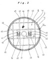
- FIG.3 is a view along the arrow headed line III-III of FIG.1.
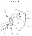
- FIG.4 is an enlarged perspective view of the section IV shown in FIG.3.
- FIG.5 is an enlarged cross-sectional view along V-V of FIG.3.
- FIG. 6 is an enlarged view along the arrow headed line VI-VI of FIG.1.
- FIG.7 is an enlarged view along the arrow headed line VII-VII of FIG.1.
- FIG.8 is an enlarged view along the arrow headed line VIII-VIII of FIG.7.
- FIG.9 is an enlarged view of the section IX shown in FIG.7.
-
- As follows is a description of a scaffold apparatus for conducting operations and an operational method according to the present invention, using the case of a CO2 blast cleaning operation of the inner wall surface of a digester (tower structure) with a blast furnace type structure employed in a paper production plant as an example.
- FIG. 1 shows a
digester 1, with a scaffold apparatus for operations, which is used for conducting a cleaning operation of the inner wall surface, erected therein. - The
digester 1 is, for example, a large scale, tall, closed vessel with an internal diameter of 4 to 5 meters and a height of 40 to 50 meters, and is classified as a type-1 pressure vessel in the safety standards. Accordingly, the state of the inner wall surface must be inspected for safety purposes, and where necessary, required inner wall surface repair operations, such as the repair, by welding, of reduced thickness sections caused by cracking or abrasion of the inner wall surface, must be carried out. When this type of welding repair of the inner wall surface is required, the inner wall surface must first be subjected to a cleaning operation as a preparatory operation. In this embodiment, a cleaning operation using a CO2 blast device, which acts as a preparatory operation for a welding repair operation, is described as an example of an operation that uses the scaffold apparatus for operations. - As follows is a simple description of the construction of the
digester 1, which represents the operation target. - The
digester 1 is formed as a sealed vessel, comprising a main body section 2 with a large diameter cylindrical structure, and adigester bottom structure 3 with an end plate construction joined at the bottom end and a digester top structure 4 joined at the top end, and is fixed in a vertical position with a bottom section 1a of thedigester bottom structure 3 supported on a base 5. - Furthermore, the main body section 2 has a so-called "bamboo construction" wherein the diameter dimension reduces in a stepwise manner from the bottom section 1a of the
digester 1 through to atop section 1b, and comprises a firstmain body section 21 that has the largest diameter and is joined to the top edge of thedigester bottom structure 3, a secondmain body section 22, which is of a smaller diameter than the firstmain body section 21 and is joined so that the bottom end thereof is inserted inside the top end of the firstmain body section 21, and a thirdmain body section 23, which is of a smaller diameter than the secondmain body section 22, is joined so that the bottom end thereof is inserted inside the top end of the secondmain body section 22, and which has the aforementioned digester top structure 4 joined to the top end thereof. Accordingly, aninner wall surface 1d of the main body section 2 has a stepped structure in which the internal diameter dimension varies at the joint regions between the firstmain body section 21 through the thirdmain body section 23. Consequently, a heightadjustable operations platform 8 described below, which is used during cleaning operations of theinner wall surface 1d, has a structure that enables vertical movement from the firstmain body section 21 through to the thirdmain body section 23 without being affected in any way by the steps at the joint sections between the main body sections. - Furthermore in this embodiment, when a cleaning operation using CO2 blasting is conducted on the inner wall surface of the
digester 1, in order to ensure good ventilation through the inside of thedigester 1, manholes that are provided in thedigester 1 for that purpose are used. In other words, the CO2 blasting is a technique in which fine particles of dry ice are projected at the target surface as a blast material, and during the blasting operation, because CO2 gas accumulates at the bottom inside thedigester 1, in order to generate a downward ventilation flow inside thedigester 1, anexhaust system 32 is attached to abottom manhole 31 provided in a central position within thedigester bottom structure 3,exhaust systems top section 1b, and anair supply device 37 is provided at alarge diameter manhole 35 provided substantially halfway up the digester. This ventilation system ensures a good working environment inside thedigester 1, and guarantees a highly safe operation. - In addition, a manhole 36 provided near the joint section between the
digester bottom structure 3 and the firstmain body section 21 of thedigester 1 is used for carrying materials in and out of thedigester 1, and for people to enter or exit from thedigester 1. - As shown in FIG. 1, the aforementioned scaffold apparatus for operations comprises a left and right pair of
posts 16, which are put up from the bottom section 1a of thedigester 1 toward thetop section 1b, and the bottom ends of which are supported by a lower fixed operations floor 6 and the top ends of which are supported by an upperfixed operations floor 7, and a heightadjustable operations platform 8 which moves up and down along each of theseposts 16. - The aforementioned lower fixed operations floor 6, the upper
fixed operations floor 7, the heightadjustable operations platform 8, and theposts 16 that make up the scaffold apparatus for operations are all divided structures, and are each carried into thedigester 1 in a disassembled state through the manhole 36, and then assembled inside thedigester 1. As follows is a description of each of the structural elements, in the order in which they are assembled. - The lower fixed operations floor 6 corresponds with the "lower support base 6" disclosed in the claims, and is the first structure assembled during erection of the scaffold apparatus for operations.
- In other words, as shown in FIG. 1, the lower fixed operations floor 6 is secured near the boundary between the straight region and the curved region of the aforementioned
digester bottom structure 3 of the digester 1 (see FIG. 4), and in addition to its original function as an operations platform, also performs the important function of acting as a support base for theposts 16 described below. - As shown in FIG. 3, the lower fixed operations floor 6 is constructed by assembling four
support girders 43 in a cross girder arrangement, and then installing and securing aflooring material 44 in a circular shape, the periphery of which extends out to a position close to, and facing theinner wall surface 1d of thedigester 1, onto the top of thesesupport girders 43. Furthermore, a left and right pair ofsupport bases posts 16 described below are provided in positions toward the center of the lower fixed operations floor 6, andpositioning stoppers 42 for restricting the sideways movement of the bottom ends of theposts 16 are provided on these support bases 41 (see FIG. 5). - As described above, the lower fixed operations floor 6 is carried from outside the
digester 1, through the manhole 36 and into the digester in a disassembled state, where it is then assembled, and consequently all of the structural members must be formed from parts that are of a size capable of passing through the manhole 36, and must be bolt secured structures that are capable of being assembled and disassembled. - Accordingly, in an assembly procedure for the lower fixed operations floor, first, the four
support girders 43 are carried into thedigester 1, and assembled in a cross girder arrangement inside thedigester 1. In other words, as shown in FIG. 4, eight securingpieces 45 are welded to theinner wall surface 1d at a position directly above the aforementioneddigester bottom structure 3 of thedigester 1 in advance, with a predetermined spacing in the circumferential direction. Each securingpiece 45 is then attached to a connectingmember 46 via abolt 18, and the end section of asupport girder 43 is then secured to the connectingmember 46 via abolt 19. The reason that the securingpieces 45 and thesupport girders 43 are joined together via the aforementioned connectingmembers 46 is to enable ready compatibility with changes in the structure of thesupport girders 43. Furthermore, when the operations have been completed and the lower fixed operations floor 6 has been disassembled and removed, these securingpieces 45 remain attached to thedigester 1, and are used in the next operation. - As shown in FIG. 1, FIG. 2, and FIG. 9, the
posts 16 are put up inside thedigester 1 so as to extend from the aforementioned lower fixed operations floor 6 through to the upper fixedoperations floor 7 described below, and in this embodiment twoposts 16 are arranged in parallel with a predetermined spacing therebetween, and are connected byjoint members 17, forming an approximately ladder type structure. The number ofposts 16 to be installed is appropriately selectable upon the needs, and either a single post, or a set of three or more posts, may be used. - As described above, the
posts 16 are carried from outside thedigester 1, through the manhole 36, and are then assembled inside, and in this embodiment, a plurality of truss structuredpost pieces 16a with a rectangular cross-section (see FIG. 9) and a length that represent a size capable of passing through the manhole 36 are prepared, and these are then joined together sequentially in an axial direction to form a column type structure. - In other words, the
post pieces 16a are carried onto the lower fixed operations floor 6 via the manhole 36. Then, as shown in FIG. 3 and FIG. 5, first, twopost pieces 16a are put up on top of the aforementioned support bases 41 of the lower fixed operations floor 6, positioned in place by thepositioning stoppers 42, and then secured in place with bolts (not shown in the drawings). Subsequently, a predetermined number ofadditional post pieces 16a are stacked on top of, and connected to, thebottommost post pieces 16a, sequentially increasing the height of the posts, and theuppermost post pieces 16a that are joined last are secured to the upper fixedoperations floor 7 described below. Furthermore, a rack 15 (see FIG. 9) that extends in the axial direction is provided on thepost pieces 16a, and when a plurality ofpost pieces 16a are joined together to form apost 16, theseracks 15 also extend continuously from the bottom end of thepost 16 to the top end. - The operation for stacking and joining the
post pieces 16a, the assembly of the upper fixedoperations floor 7, and the operation for joining the floor to the top end of theposts 16, are carried out using the heightadjustable operations platform 8 described below. In other words, in the operation of putting up theposts 16, once thebottommost post pieces 16a have been attached, the aforementioned heightadjustable operations platform 8 is assembled on the lower fixed operations floor 6 and attached to thesepost pieces 16a, and is then raised and lowered along thesepost pieces 16a. This heightadjustable operations platform 8 is then moved sequentially upward, while thepost pieces 16a are sequentially stacked and joined together. Furthermore, in this case, the disassembled parts for the aforementioned upper fixedoperations floor 7 are loaded onto the heightadjustable operations platform 8, and following completion of the joining operation of theuppermost post pieces 16a, the upper fixedoperations floor 7 is assembled on top of the heightadjustable operations platform 8 and then secured to the top end of the posts 16 (namely, the top end of theuppermost post pieces 16a). This completes the assembling of theposts 16, the bottom ends of which are supported by the lower fixed operations floor 6, and the top ends of which are supported by the upper fixedoperations floor 7. - The upper fixed
operations floor 7 corresponds with the "upper support base" disclosed in the claims, and as shown in FIG. 1, is disposed at a position immediately below the digester top structure 4 of thedigester 1, and in addition to functioning as an operations floor as per its original function, also performs the important function of acting as a top end support base for theposts 16 as described above. - As shown in FIG. 6, the upper fixed
operations floor 7 is a circular, flat shape, and is positioned inside theside walls 1c of thedigester 1 with a predetermined space retained between the floor and theside walls 1c. Furthermore, the upper fixedoperations floor 7 supports the top ends of the aforementioned pair ofposts post securing members jacks inner wall surface 1d of theside walls 1c. - In the same manner as the lower fixed operations floor 6 described above, this upper fixed
operations floor 7 is also a knockdown structure that is bolted together, and is carried into thedigester 1 through the aforementioned manhole 36, and then assembled on top of the heightadjustable operations platform 8. - The height
adjustable operations platform 8 is used as an operations floor for the cleaning operation conducted on theinner wall surface 1d of thedigester 1 as in this embodiment, but is also used as the operations floor for a wide variety of other operations such as inspection operations or repair operations conducted on theinner wall surface 1d, and for the transport and transfer of operating materials or operators during any of these operations. - A shown in FIG. 7, the height
adjustable operations platform 8 is formed as a circular shaped flat structure by attaching aflooring material 49 to the top ofgirder members inner wall surface 1d of thedigester 1. A left and right pair of post guides 62, 62 are provided in the central region of this heightadjustable operations platform 8, and theaforementioned posts bevel gears posts 16 to which theracks 15 are attached, as shown in FIG. 7 and FIG. 9, and these pinion gears 40 engage with, and travel along theracks 15 on the side of theposts 16, enabling the heightadjustable operations platform 8 to move up and down along theposts 16 under its own power. - In addition, as shown in FIG. 7 and FIG. 8,
guide wheel units 9 are provided at four locations around the outer periphery of the heightadjustable operations platform 8. Theseguide wheel units 9 run along theinner wall surface 1d of thedigester 1 when the heightadjustable operations platform 8 is raised or lowered, restricting sideways deviation of the heightadjustable operations platform 8 and ensuring stable up and down movement. - In other words, the
guide wheel units 9 are constructed by attaching awheel 10 to the tip of a pivotedarm 11, which is provided on the heightadjustable operations platform 8 and is free to swing in the radial direction of thedigester 1, and then using adamper 12 to energize thearm 11 to apply pressure continually in the outward direction. According to such a construction, because thewheels 10 run along theinner wall surface 1d while being pressed against the inner wall surface with a constant, predetermined pressure, stability during the raising and lowering of the heightadjustable operations platform 8 is ensured at all times, and because thewheels 10 are free to deviate along the radial direction of thedigester 1, thewheels 10 are able to accommodate steps (namely, the joint sections between the first through thirdmain body sections 21 to 23 of the main body section 2) in theinner wall surface 1d, and easily ride over such steps, meaning the reliability of the movement of the heightadjustable operations platform 8 is ensured. - Because the height
adjustable operations platform 8 is carried through the manhole 36 from outside thedigester 1, and is then assembled inside the digester, each structural member must be a knockdown structure formed from parts that are of a size capable of passing through the manhole 36, which are then bolted together. - C: Cleaning Operation using the Scaffold Apparatus for Operations
- As follows is a description of the operating procedure for conducting a CO2 blast cleaning operation on the
inner wall surface 1d of theaforementioned digester 1 using the scaffold apparatus for operations described above. - As described above, in the aforementioned scaffold apparatus for operations that has been assembled inside a
digester 1, the aforementioned heightadjustable operations platform 8 is freely raised and lowered along theposts 16 between the lower fixed operations floor 6 and the upper fixedoperations floor 7, and consequently, as shown in FIG. 1 and FIG. 2, an operator M is placed on the heightadjustable operations platform 8,hoses 24 extending from a CO2blast operations unit 20 located outside thedigester 1 are passed through thebottom manhole 31 provided in thedigester bottom structure 3 of thedigester 1 and up onto the top of the heightadjustable operations platform 8, the operator M holds ablast nozzle 54 attached to the tip of thehoses 24, and a blast material, namely fine particles of dry ice, projected from theblast nozzle 54 is sprayed onto theinner wall surface 1d, and the impact energy of the blast material removes adherents such as rust from the surface of theinner wall surface 1d, thereby producing a clean surface. By conducting this cleaning operation while the heightadjustable operations platform 8 is sequentially raised or lowered by predetermined distance, the cleaning operation is performed in a uniform manner over the entire height of theinner wall surface 1d. - In this case, because the blast material sublimes after projection and becomes CO2 gas, a post-operation for recovering the blast material, such as that required when steel spheres or the like are used as the blast material, is unnecessary, meaning the operation is very favorable in terms of improving the operating efficiency of the overall cleaning operation, and reducing the operating costs. Furthermore, because of the difference in specific gravity from air, the CO2 gas accumulates at the bottom of the
digester 1, and because a downward ventilation flow exists inside thedigester 1, discharge of the gas outside thedigester 1 is performed very efficiently, the operating environment inside thedigester 1 is maintained at a good condition, and the gas causes absolutely no harm to the health of the operator M. Coarse particulates generated by the blasting also get carried along the downward flow and are discharged externally from thedigester 1, but to avoid inhalation of these coarse particulates, anair line mask 53 is passed into thedigester 1 from theaforementioned manhole 35, as shown in FIG. 1, and the operator M wears this mask. - Focusing on the utility of the height
adjustable operations platform 8, because thewheels 10 of each of theguide wheel units 9 brace the heightadjustable operations platform 8 against theinner wall surface 1d, sideways swinging during raising or lowering of the platform is largely inhibited, enabling a more stable, smoother movement, and improving the safety during movement, and furthermore, during a cleaning operation while the heightadjustable operations platform 8 is stopped, even if, for example, the projection of the blast material from theblast nozzle 54 causes a reaction force, the platform is maintained in a stable state with no sideways rolling, enabling a very uniform cleaning operation to be conducted on theinner wall surface 1d, and ensuring good reliability for the operation. - In addition, because the
wheels 10 of theguide wheel units 9 are capable of being displaced freely toward, and away from, theinner wall surface 1d, when the heightadjustable operations platform 8 moves over the joint sections between the firstmain body section 21 through the thirdmain body section 23 of the main body section 2, even if there are steps formed at these joint sections, by utilizing the aforementioned displacement function, thewheels 10 easily ride over such steps, and steps in theinner wall surface 1d cause absolutely no impediment to the movement of the heightadjustable operations platform 8. As a result, stable vertical movement of the heightadjustable operations platform 8 is achieved, meaning the general purpose applicability of the scaffold apparatus for conducting operations on the inner wall surfaces of tower structures of a variety of constructions is improved even further. - Furthermore, because the height
adjustable operations platform 8 is equipped with theaforementioned motors 30 and is capable of being raised and lowered under its own power, during various operations that use the heightadjustable operations platform 8, adjustments to the height of the heightadjustable operations platform 8 is performed easily and quickly, for example in accordance with the requirements of an operator, meaning both the operability and mobility are good. As a result, the operating efficiency of operations that are conducted using the heightadjustable operations platform 8 is improved markedly. - Furthermore on the other hand, focusing on the utility of the entire scaffold apparatus for operations, which incorporates the height
adjustable operations platform 8, then in the above embodiment, if theaforementioned posts 16 are put up inside thedigester 1 and the heightadjustable operations platform 8 is then attached to theposts 16, then adjustments of the installation height of the heightadjustable operations platform 8 within the digester 1 (that is, the height position at which operations are conducted using the height adjustable operations platform 8) is performed easily and quickly by moving the heightadjustable operations platform 8 up or down along theposts 16, and consequently, compared with a conventional case in which, for example, a level adjustment operation such as adding to the scaffold framework is required inside thedigester 1 every time the operating height is altered, the operability of inner wall surface operations improves markedly, and because level adjustment operations need not be conducted at great heights, the safety of the operations also improves, meaning both operating cost reductions and improved safety are achieved. - Furthermore, in this embodiment, the aforementioned lower fixed operations floor 6 is attached via the securing
pieces 45 provided on theside wall 1c of thedigester 1 immediately above thetower bottom structure 3, and the bottom ends of theaforementioned posts 16 are supported by this lower fixed operations floor 6, and consequently the entire weight, including the dead load of theposts 16 and the attached heightadjustable operations platform 8, and the weight of the operator M and/or operating materials loaded onto this heightadjustable operations platform 8, is supported directly by theside walls 1c at a point immediately above thetower bottom section 3 of thedigester 1, via the lower fixed operations floor 6, and the application of load onto thetower bottom section 3 is avoided. As a result, compared with the case in which the entire weight of theposts 16 and the like are supported by thetower bottom section 3 of thedigester 1 that is, the region that is typically constructed from an end plate with a curved surface, the weight of theposts 16 and the like is supported more reliably and in a more stable manner, and both the reliability of the installation of theposts 16 and the like, and the reliability of the various operations conducted using theposts 16 and the attached heightadjustable operations platform 8 are improved. Moreover, because thetower bottom section 3 of thedigester 1 has the end plate structure described above, that section is more complex and more expensive to produce than theside wall section 1c, and consequently by not needing to use thistower bottom section 3 as the support site for theposts 16 and the like, damage to thetower bottom section 3 is effectively avoided, resulting in an improvement of the durability of thedigester 1, or a reduction of the production costs. - In the embodiment described above, the
digester 1 was described as one example of the "tower structure" that is the target of the present invention, but the "tower structure" is not restricted to structures such as thedigester 1 with a blast furnace type construction, and for example, also includes comparatively low structures such as oil storage tanks and the like. Furthermore, the aforementioned"tower structure" is not restricted to pressure vessels such as theaforementioned digester 1, it may be used with comparatively low-pressure structures too. - Furthermore, in the above embodiment, a cleaning operation conducted on the inner wall surface of the
digester 1 was described as an example of an operation using the scaffold apparatus for operations, but the scaffold apparatus for operations according to the present invention is not restricted to this operation, and is also ideally applied to a variety of other operations including inspection operations, modification operations, and welding operations. Furthermore, each of these different types of operations is of course conducted individually, or a plurality of operations is conducted conjointly, in parallel. - As described above, the present invention comprises either a single post or a plurality of posts put up inside a tower structure from a bottom section thereof toward a top section, and a height adjustable operations platform that is attached in a manner that enables free up or down movement along the posts, and consequently, assembling the posts inside the tower structure and then attaching the height adjustable operations platform means that when any of a variety of operations are conducted on the inner wall surfaces of the tower structure, adjustments of the installation height of the height adjustable operations platform within the tower structure is performed easily and quickly by moving the height adjustable operations platform up or down along the posts, and consequently, a level adjustment operation such as adding to the scaffold framework is not required inside the tower structure every time the operating height is altered, enabling a marked improvement in the operability of inner wall surface operations, and in addition, because level adjustment operations need not be conducted at great heights, the safety of the operations improves, meaning the invention is also ideal for achieving both operating cost reductions and improved safety.
Claims (6)
- A scaffold apparatus for conducting operations on an inner wall surface of a tower structure, comprising either a single post or a plurality of posts (16) put up inside a tower structure (1), from a bottom section thereof toward a top section, and a height adjustable operations platform (8) that is attached in a manner that enables free up or down movement along said posts (16).
- The scaffold apparatus for conducting operations on an inner wall surface of a tower structure according to claim 1, wherein said posts (16) are assembled by sequentially stacking and connecting a plurality of posts pieces (16a), which are of dimensions that enable transport through a materials transport port (36) provided in said tower structure (1), from the bottom section (1a) of said tower structure (1) toward the top section (1b).
- The scaffold apparatus for conducting operations on an inner wall surface of a tower structure according to claim 1 or claim 2, wherein a bottom end of each post (16) is supported by a lower support base (6), which is secured immediately above a tower bottom section (3) via securing pieces (45) provided on a side wall (1c) of said tower structure (1) immediately above said tower bottom section (3).
- The scaffold apparatus for conducting operations on an inner wall surface of a tower structure according to claim 1, wherein said height adjustable operations platform (8) is a knockdown structure that is capable of being transported through a materials transport port (36) provided in said tower structure (1).
- The scaffold apparatus for conducting operations on an inner wall surface of a tower structure according to claim 4, wherein said height adjustable operations platform (8) is equipped with elevation drive means (30), which enables said platform to be raised and lowered under its own power, and an external periphery of said height adjustable operations platform (8) is equipped with a guide wheel unit (9) that is provided with a wheel (10), which is capable of being displaced freely toward, and away from, an inner wall surface (1d) of said tower structure (1) and is held in continuous contact with said inner wall surface (1d) by a predetermined pressure.
- An operational method for an inner wall surface of a tower structure, comprising the steps of: loading a person and/or an operating material onto a height adjustable operations platform (8), which is attached to a single post or a plurality of posts (16) put up inside a tower structure (1) from a bottom section thereof toward a top section in a manner that enables free up or down movement along said posts (16); and adjusting an operating height by moving said platform up and down along said posts (16), while performing required operations on an inner wall surface (1d) of said tower structure (1).
Applications Claiming Priority (3)
| Application Number | Priority Date | Filing Date | Title |
|---|---|---|---|
| JP2002163776A JP4209635B2 (en) | 2002-06-05 | 2002-06-05 | Scaffolding device for inner wall surface work of tower tank body and inner wall surface working method using the scaffolding device |
| JP2002163776 | 2002-06-05 | ||
| PCT/JP2003/007046 WO2003104585A1 (en) | 2002-06-05 | 2003-06-03 | Scaffolding device for work on inner wall face of tower vessel body, and method of work on inner wall face using the scaffolding device |
Publications (1)
| Publication Number | Publication Date |
|---|---|
| EP1553244A1 true EP1553244A1 (en) | 2005-07-13 |
Family
ID=29727552
Family Applications (1)
| Application Number | Title | Priority Date | Filing Date |
|---|---|---|---|
| EP03730815A Withdrawn EP1553244A1 (en) | 2002-06-05 | 2003-06-03 | Scaffolding device for work on inner wall face of tower vessel body, and method of work on inner wall face using the scaffolding device |
Country Status (7)
| Country | Link |
|---|---|
| US (1) | US20050247008A1 (en) |
| EP (1) | EP1553244A1 (en) |
| JP (1) | JP4209635B2 (en) |
| CN (1) | CN1659346A (en) |
| BR (1) | BR0309741A (en) |
| CA (1) | CA2482742A1 (en) |
| WO (1) | WO2003104585A1 (en) |
Cited By (1)
| Publication number | Priority date | Publication date | Assignee | Title |
|---|---|---|---|---|
| US9382719B2 (en) | 2013-09-10 | 2016-07-05 | Alstom Renewable Technologies | Platform for accessing a hydraulic machine and methods for installing and disassembling such a platform in a suction tube |
Families Citing this family (19)
| Publication number | Priority date | Publication date | Assignee | Title |
|---|---|---|---|---|
| ES2283192B1 (en) * | 2005-09-16 | 2008-09-16 | GAMESA INNOVATION & TECHNOLOGY, S.L. | METHOD OF ASSEMBLY OF ELEMENTS INSIDE THE TOWER OF AN AEROGENERATOR. |
| JP4843327B2 (en) * | 2006-02-14 | 2011-12-21 | 雅明 五十嵐 | Construction method of temporary scaffolding inside a hollow structure |
| US20110140437A1 (en) * | 2010-05-26 | 2011-06-16 | Satish Vemuri | Self-supporting platform for a wind turbine |
| HK1172197A2 (en) * | 2012-06-01 | 2013-04-12 | Wls Intellectual Property Limited | Improvements in building components and structures |
| DE102012109860A1 (en) * | 2012-10-16 | 2014-04-17 | Max Bögl Wind AG | Supply tower for a tower, tower with a utility scaffold and method for erecting a utility scaffolding inside a tower |
| CN104120870A (en) * | 2013-04-28 | 2014-10-29 | 中际联合工业技术(北京)有限公司 | Temporary operating platform |
| DE102013217088A1 (en) * | 2013-08-27 | 2015-03-05 | Senvion Se | Method for assembling tower installations |
| US9487960B2 (en) * | 2014-06-17 | 2016-11-08 | One Energy Enterprises Llc | Suspended deck systems, kits, and methods of installing, inspecting, and repairing a suspended deck system |
| CN104594631B (en) * | 2015-02-05 | 2016-06-29 | 中化二建集团有限公司 | The construction technology of sliding form apparatus traction operation platform construction granulation tower spraying layer |
| DE102017002525B4 (en) | 2017-03-16 | 2020-06-04 | Goracon Engineering Gmbh | Working platform for the construction of tower segments and towers of wind turbines, for example |
| EP3425136B1 (en) * | 2017-07-05 | 2020-02-26 | Alimak Group Management AB | Transportation systems, elevator systems, kits, tower sections and methods for performing assembly or maintenance operations in towers |
| US11136967B2 (en) * | 2018-07-02 | 2021-10-05 | Inventus Holdings, Llc | Articulating joint for wind turbine |
| US20220056890A1 (en) * | 2018-11-15 | 2022-02-24 | Vestas Wind Systems A/S | A logistics system for a multirotor wind turbine |
| CN109556978B (en) * | 2019-01-23 | 2024-03-15 | 上汽大众汽车有限公司 | Drop-out impact test equipment |
| CN110410277B (en) * | 2019-08-09 | 2023-11-24 | 戚永维 | A wind turbine tower and its installation method |
| CN111441565A (en) * | 2020-03-18 | 2020-07-24 | 航天海鹰(哈尔滨)钛业有限公司 | Lifting device for limited space operation of hot isostatic pressing machine and use method |
| CN113898154A (en) * | 2021-08-24 | 2022-01-07 | 上海宝冶集团有限公司 | Adjustable wall body moisturizing device |
| CN116464255B (en) * | 2023-03-29 | 2025-05-09 | 山东送变电工程有限公司 | A steel pipe tower station platform with adjustable installation dimensions |
| CN117401530B (en) * | 2023-12-14 | 2024-02-23 | 招远市河西金矿有限公司 | Blind shaft wellhead maintenance platform |
Family Cites Families (3)
| Publication number | Priority date | Publication date | Assignee | Title |
|---|---|---|---|---|
| JP3415925B2 (en) * | 1994-04-22 | 2003-06-09 | 良忠 越原 | Elevator for construction |
| JP3258582B2 (en) * | 1996-11-29 | 2002-02-18 | 三菱重工業株式会社 | Scaffolding for beverage tanks |
| JP2001193278A (en) * | 2000-01-07 | 2001-07-17 | Kajima Corp | Construction method and climbing scaffold for structures with internal space |
-
2002
- 2002-06-05 JP JP2002163776A patent/JP4209635B2/en not_active Expired - Fee Related
-
2003
- 2003-06-03 WO PCT/JP2003/007046 patent/WO2003104585A1/en not_active Ceased
- 2003-06-03 CN CN038127717A patent/CN1659346A/en active Pending
- 2003-06-03 US US10/509,844 patent/US20050247008A1/en not_active Abandoned
- 2003-06-03 CA CA002482742A patent/CA2482742A1/en not_active Abandoned
- 2003-06-03 BR BR0309741-2A patent/BR0309741A/en not_active Application Discontinuation
- 2003-06-03 EP EP03730815A patent/EP1553244A1/en not_active Withdrawn
Non-Patent Citations (1)
| Title |
|---|
| See references of WO03104585A1 * |
Cited By (2)
| Publication number | Priority date | Publication date | Assignee | Title |
|---|---|---|---|---|
| US9382719B2 (en) | 2013-09-10 | 2016-07-05 | Alstom Renewable Technologies | Platform for accessing a hydraulic machine and methods for installing and disassembling such a platform in a suction tube |
| EP2845966B1 (en) * | 2013-09-10 | 2020-10-28 | GE Renewable Technologies | Platform for accessing a hydraulic machine and methods for installing and disassembling such a platform in a suction tube |
Also Published As
| Publication number | Publication date |
|---|---|
| CA2482742A1 (en) | 2003-12-18 |
| JP2004011193A (en) | 2004-01-15 |
| WO2003104585A1 (en) | 2003-12-18 |
| CN1659346A (en) | 2005-08-24 |
| US20050247008A1 (en) | 2005-11-10 |
| BR0309741A (en) | 2005-03-22 |
| JP4209635B2 (en) | 2009-01-14 |
Similar Documents
| Publication | Publication Date | Title |
|---|---|---|
| US20050247008A1 (en) | Scaffolding device for work on inner wall face of tower vessel body, and method of work on inner wall face using the scaffolding device | |
| CN110998042B (en) | Transport system, kit and method for performing assembly or maintenance operations in a tower structure | |
| CN102235107B (en) | Hydraulic lifting construction method for chimney steel inner cylinder | |
| CA2473926A1 (en) | Working device for inner wall surface of tower tank, and inner wall surface working method using the same | |
| US10337194B2 (en) | Work platform system configured for use structure with internal cavity, and related methods of assembly and use | |
| CN113585087A (en) | A easy dismouting template supporting platform for tie beam construction | |
| CN109879179B (en) | Assembled steel construction tower crane platform | |
| CN110847031A (en) | Mobile gondolas for bridge construction | |
| CN114408735A (en) | Rotatable multi-purpose formula waterwheel room jack-up overhauls platform | |
| CN203486787U (en) | Integral lifting device for cabinet top of Wiggins coal gas cabinet | |
| CN113309330A (en) | Auxiliary device for assembling large tank | |
| JPH09268778A (en) | Dismantling method of water-containing gas holder and members used for the method | |
| JP5299982B1 (en) | Wall linking band for cylindrical structure construction / repair work, and method for construction / repair of cylindrical structure by moving lifting type scaffolding using the wall linking band | |
| JP2010090633A (en) | Prefabricated work platform for cylindrical concrete structure | |
| CN118951264A (en) | A plasma underwater cutting method | |
| CN118186912A (en) | A kind of assembled beam-column bracket and bracket construction method | |
| JP3757509B2 (en) | Construction method of water-containing gas holder | |
| JPH07102793A (en) | Method and apparatus for dismantling tower | |
| CN212270670U (en) | Movable hanging basket for bridge construction | |
| CN210857939U (en) | Scaffold moving platform base | |
| CN214701974U (en) | Chimney blasting is demolishd and is pushed down device with single action | |
| CN222414066U (en) | Frame type concrete placing support for small spaces | |
| JP4839052B2 (en) | Rotating dismantling method of storage tank | |
| CN223317505U (en) | A high-altitude assembly construction operation platform for rotary kiln cylinders | |
| CN117365134B (en) | Assistant mounting system for assembled rectangular steel column and using method thereof |
Legal Events
| Date | Code | Title | Description |
|---|---|---|---|
| PUAI | Public reference made under article 153(3) epc to a published international application that has entered the european phase |
Free format text: ORIGINAL CODE: 0009012 |
|
| 17P | Request for examination filed |
Effective date: 20041222 |
|
| AK | Designated contracting states |
Kind code of ref document: A1 Designated state(s): AT BE BG CH CY CZ DE DK EE ES FI FR GB GR HU IE IT LI LU MC NL PT RO SE SI SK TR |
|
| RBV | Designated contracting states (corrected) |
Designated state(s): ES FI SE |
|
| REG | Reference to a national code |
Ref country code: DE Ref legal event code: 8566 |
|
| STAA | Information on the status of an ep patent application or granted ep patent |
Free format text: STATUS: THE APPLICATION IS DEEMED TO BE WITHDRAWN |
|
| 18D | Application deemed to be withdrawn |
Effective date: 20070103 |