EP1553034A2 - Verfahren und Vorrichtung zur Steuerung von Ereignissen synchron zu einer bewegten Materialbahn - Google Patents
Verfahren und Vorrichtung zur Steuerung von Ereignissen synchron zu einer bewegten Materialbahn Download PDFInfo
- Publication number
- EP1553034A2 EP1553034A2 EP05000156A EP05000156A EP1553034A2 EP 1553034 A2 EP1553034 A2 EP 1553034A2 EP 05000156 A EP05000156 A EP 05000156A EP 05000156 A EP05000156 A EP 05000156A EP 1553034 A2 EP1553034 A2 EP 1553034A2
- Authority
- EP
- European Patent Office
- Prior art keywords
- brand
- web
- signal
- pattern
- brightness
- Prior art date
- Legal status (The legal status is an assumption and is not a legal conclusion. Google has not performed a legal analysis and makes no representation as to the accuracy of the status listed.)
- Withdrawn
Links
Images
Classifications
-
- B—PERFORMING OPERATIONS; TRANSPORTING
- B65—CONVEYING; PACKING; STORING; HANDLING THIN OR FILAMENTARY MATERIAL
- B65H—HANDLING THIN OR FILAMENTARY MATERIAL, e.g. SHEETS, WEBS, CABLES
- B65H23/00—Registering, tensioning, smoothing or guiding webs
- B65H23/04—Registering, tensioning, smoothing or guiding webs longitudinally
- B65H23/18—Registering, tensioning, smoothing or guiding webs longitudinally by controlling or regulating the web-advancing mechanism, e.g. mechanism acting on the running web
- B65H23/188—Registering, tensioning, smoothing or guiding webs longitudinally by controlling or regulating the web-advancing mechanism, e.g. mechanism acting on the running web in connection with running-web
- B65H23/1882—Registering, tensioning, smoothing or guiding webs longitudinally by controlling or regulating the web-advancing mechanism, e.g. mechanism acting on the running web in connection with running-web and controlling longitudinal register of web
-
- B—PERFORMING OPERATIONS; TRANSPORTING
- B65—CONVEYING; PACKING; STORING; HANDLING THIN OR FILAMENTARY MATERIAL
- B65H—HANDLING THIN OR FILAMENTARY MATERIAL, e.g. SHEETS, WEBS, CABLES
- B65H2511/00—Dimensions; Position; Numbers; Identification; Occurrences
- B65H2511/50—Occurence
- B65H2511/51—Presence
- B65H2511/512—Marks, e.g. invisible to the human eye; Patterns
-
- B—PERFORMING OPERATIONS; TRANSPORTING
- B65—CONVEYING; PACKING; STORING; HANDLING THIN OR FILAMENTARY MATERIAL
- B65H—HANDLING THIN OR FILAMENTARY MATERIAL, e.g. SHEETS, WEBS, CABLES
- B65H2553/00—Sensing or detecting means
- B65H2553/40—Sensing or detecting means using optical, e.g. photographic, elements
- B65H2553/43—Bar code reader
Definitions
- the invention relates to a method and a device for Control of events synchronous to a moving Material web according to the preamble of claim 1 or claim 11.
- Such an event or series of Events that synchronize to a high accuracy moved material web to be controlled for example, an observation of a moving printing web represent by means of a video camera, in which the recorded Picture frozen by a flash lighting and is recorded. The moment of triggering the flash determines which image content has been captured on the camera is.
- Another improvement uses an ID code brand, which is recognized on the basis of its given pattern and can be used as a fixed point on the track. It will Although possible, the brand in an environment of print motifs However, the disadvantage remains that the brand must be relatively large in order to lateral Trajectories still to be found.
- the printing web On the material web, in particular the printing web, is of a printing cylinder periodically (usually per Cylinder revolution once) a trademark (code mark) printed using dashes and spaces different dimensions. Over the track, in the this mark pattern is printed is the invention Device arranged.
- the trade mark pattern becomes recorded in the subsequent evaluation process preferably a brand recognition for the connected Process reached quickly enough.
- This training is advantageous in that as the Influence of brightness fluctuations, for example caused by ambient light changes, as well as the Background to the signal formation is significantly reduced.
- the emergence of the output signals is practically a local differentiation of the gray value curve, by the only at the brightness transitions a signal peak formed becomes.
- About a threshold operation are preferably all Signals are cut below a defined level, so that only significant light / dark transitions be marked.
- the distances between the light / dark transitions are with the corresponding known distances from an ID code mark put into proportion and directly with a previously determined Ratio compared.
- the device according to the invention has a measuring head, with a lighting device, a cell sensor element, that is preferably a photodiode double line represents, in which both cells are parallel to each other and are arranged perpendicular to the direction of movement, a Calculator with a memory, which signals the two Evaluates photodiode lines at high speed and an output which, upon detection of a Match of current code and pattern a signal emits.
- a cell sensor element that is preferably a photodiode double line represents, in which both cells are parallel to each other and are arranged perpendicular to the direction of movement
- a Calculator with a memory, which signals the two Evaluates photodiode lines at high speed and an output which, upon detection of a Match of current code and pattern a signal emits.
- This signal is synchronous with high accuracy and can for controlling, for example, an image recording of a Video camera, to be used.
- the code mark is made of bars of alternating brightness (Alternatively, changing colors can be provided, the perceived as brightness change of the sensor array are) and is preferably a previously known Pattern of light / dark arrangements and thus transitions.
- the preferably provided beams lie in the web running direction seen one behind the other and thereby run when moving the Trace under the sensor array through.
- controller according to the method or the device according to the invention in a running web, which is also printed with other print motifs, permanent must be done is preferably a calculator structure provided, which performs the evaluation practically continuously and in the described application, the output signal with only very short delay, preferably less than 6 ⁇ s is.
- the arithmetic unit may preferably be constructed so that the comparison process is parallel for all sensor elements the sensor arrangement is executed and thus almost immediately, if a coincidence is reached in a lane, the Output signal is formed.
- the model can also be a calculator and a method chosen be in the recorded signals first cached and then processed sequentially.
- this can Process part be formed so that when parallel Reading out the lines immediately this difference value is formed and then proceed as described above.
- a further method step is inserted, accordingly the in signal formed in a preceding process step is further processed if it is below a defined Threshold is.
- Sensor element consisting of a number of individual sensors be used.
- a standard distance can be in the inventive method of Distance between at least two previous signals to be used.
- the standard distance is the distance between any two selected distances from the Signal sequence used.
- Illumination device preferably a constant light source be provided for adequate illumination of the Recording field provides.
- a LED lighting is used.
- a source consists of discrete ones Light-emitting surfaces.
- This training can be used others, the brightness distribution on the sensor affecting effects, e.g. the edge drop of an optic, to compensate.
- This can be done, for example happen that driving the luminescent diodes with according to different currents, so that individual diodes also shine differently strong and thus cause a non-homogeneous illumination on the measurement object, but their distribution is precisely designed so that they, superimposed with the edge drop of the lens, a uniform Signal generated on the sensor.
- the same can also be done be achieved that the arrangement of the light emitting elements in a different surface density (diodes each Area unit) or in a respectively adapted different distance from the measuring field.
- the passing object in particular the material web, becomes advantageously via an optical system on the sensor level displayed.
- the arrangement of the light source and the Sensor arrangement depends on which type of Underground (reflective, transparent, pronounced ...) the Trademark or Code mark has been and can be printed to serve different lighting principles, such as for example, a dark field illumination or a Bright field illumination.
- the calculator is integrated with the measuring head such that such a unit only needs a power supply as well an output line and possibly a bus interface to Communication needed.
- inventive method and the Device according to the invention a training, the Real-time recognition process.
- the device according to the invention preferably also has Sensor elements, which at an angle to the web running direction of> 0 ° are arranged.
- the angle between the web running direction and the sensor elements here at 90 °.
- the sensor cells in which the sensor elements are arranged, parallel are arranged.
- the sensor lines integrated in a sensor.
- the arithmetic unit is a freely programmable logic device (FPGA device), which includes all operations.
- FPGA device freely programmable logic device
- the individual sensor elements can in the inventive Device further consist of lines that are not more than 128 Include sensor elements.
- the exist Sensor elements themselves in turn from a number of Individual sensors.
- two CCD cells Charged Couple Devices
- the sensor elements can be a CMOS area sensor is provided, of which at least selected two lines are provided for evaluation.
- the device according to the invention can be constructed in this way be that the light-emitting elements individually so be controlled that the emitted light power through other assemblies or elements caused known compensated for local inhomogeneities.
- the arrangement of the light-emitting elements can Preferably, be chosen such that they by a different density in the arrangement by others Assemblies or elements caused known local Inhomogeneities compensated.
- the arrangement of the light-emitting elements so it is chosen by a different distance the light emitting elements of the illuminated surface is suitable, by other assemblies or elements caused known local inhomogeneities compensate.
- the lighting device may preferably have a Light stripes parallel to the arrangement of the sensor lines produce.
- a device for Signal preprocessing be arranged between the sensor arrangement and the calculating unit.
- the Signal processing devices of the invention Device a controller for controlling or regulating the Calculator, the lighting control device and the Has interfaces.
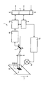
- the device 1 shown in the drawing has first a lighting device 1a, which in the particular preferred embodiment shown with a Lighting control 1b is connected.
- the Lighting device 1a is used to illuminate one measuring material web image area of a material web 10.
- the image area is in Example trap provided with a brand pattern 3 that off three arranged in the web running direction L one behind the other Brand elements 3a, 3b and 3c is constructed. in principle However, it would also be possible to have only two brand elements or to provide a greater number of these elements.
- the device 1 has a Signal processing device, which in the illustrated Embodiment an arithmetic unit 4a, an interface 7 and a Controller or a control / regulating device 9 has. Between the material web 10 and a sensor arrangement 2, the in the illustrated embodiment as a line sensor element is formed, an optic 5 is arranged. Between the Sensor assembly 2 and the calculator 4a is in the particular preferred embodiment according to the drawing a Device 4b arranged for signal preprocessing.
- the arithmetic unit 4a is also in mutual relationship with an output (trigger) 6 and the controller 9 coupled. Of the Controller 9 in turn is connected to the device 1b for Lighting control and the interface 7 coupled. Finally, the device 1 according to the invention has a Power supply 8 on.
- the one shown in the figure Embodiment of the device 1 according to the invention is used preferably for carrying out the initially described Method for controlling events synchronous to the moving web of material 10 by means of a comparison of on the Material web 10 located brand pattern 3 with a predetermined brand pattern.
Landscapes
- Length Measuring Devices By Optical Means (AREA)
- Inking, Control Or Cleaning Of Printing Machines (AREA)
- Controlling Sheets Or Webs (AREA)
- Accessory Devices And Overall Control Thereof (AREA)
Abstract
Description
- 1
- Vorrichtung
- 1a
- Beleuchtungseinrichtung
- 1b
- Beleuchtungssteuerung
- 2
- Sensoranordnung
- 3
- Markenmuster
- 3a-3c
- Markenelemente
- 4a
- Rechenwerk
- 4b
- Signalvorverarbeitung
- 5
- Optik
- 6
- Ausgang
- 7
- Interface
- 8
- Spannungsversorgung
- 9
- Controller
- 10
- Materialbahn
- L
- Laufrichtung der Materialbahn
Claims (14)
- Verfahren zur Steuerung von Ereignissen synchron zu einer bewegten Materialbahn mit folgenden Verfahrensschritten:Erfassen von Helligkeits- und/oder Farbkontrastunterschieden von in Bahnlaufrichtung hintereinander auf die Materialbahn aufgebrachten Markenmustern zum Zwecke der Identifikation des Markenmusters;wobei die Abtastung der Markenmuster durch zumindestens zwei hintereinander angeordnete zeilenförmige Sensoren erfolgt, die aus mehreren diskreten nebeneinander liegenden Sensorelementen bestehen;Vergleich des auf die Materialbahn aufgebrachten und erfassten Markenmusters mit einem vorgegebenen Markenmuster; undAusgeben eines Steuersignales entsprechend dem Ergebnis des durchgeführten Vergleiches.
- Verfahren nach Anspruch 1, bei dem aus den Messwerten der zwei hintereinander angeordneten Sensorelemente verschiedener Zeilen eine Differenz gebildet wird und dies für jedes Sensorelementpaar erfolgt und auf diese Weise eine Differenzierung des von einer Zeile aufgenommenen Helligkeitsverlaufes vorgenommen wird.
- Verfahren nach Anspruch 1 oder 2, bei dem die Abstände zwischen den verbleibenden impulsförmigen Signalen für jede aus zwei Sensorelementen gebildete Signalfolge in ein Verhältnis zu einem Normabstand gesetzt wird, sodass für jede Signalfolge eine eigene Folge von Abstandsverhältnissen entsteht.
- Verfahren nach Anspruch 3, bei dem die Verhältnisfolgen jeweils mit denen für das bekannte Markenmuster verglichen werden.
- Verfahren nach Anspruch 4, bei dem für den Fall, dass für mindestens eine Verhältnisfolge eine Übereinstimmung mit dem bekannten Muster erkannt wird, ein Ausgangssignal gesetzt wird.
- Verfahren nach einem der Ansprüche 1 bis 3, bei dem aus dem Signalverlauf jeweils mindestens zwei Wendepunkte gefunden werden und ein Ausgangssignal gebildet wird, das sich jeweils am Wendepunkt seiner Amplitude um einen Mindestbetrag verändert.
- Verfahren nach einem der Ansprüche 1 bis 6, bei dem als Normabstand der Abstand zwischen zumindestens zwei vorausgegangenen Signalen benutzt wird.
- Verfahren nach Anspruch 1-7, bei dem eine Schwelle aus einem Histogramm der einlaufenden Messwerte gebildet wird, wobei das Histogramm über eine Umdrehung des Druckformzylinders oder einen Nutzen bei bekannter Nutzengröße gewonnen wird, und die Schwelle sich um etwa 10 % bzw. 25 % vom Helligkeitswert des Untergrundes unterscheidet.
- Verfahren nach einem der Ansprüche 1 bis 8, bei dem der Grad der Übereinstimmung durch Toleranzwerte vorgegeben wird.
- Verfahren nach einem der Ansprüche 1 bis 9, bei dem zusätzlich eine Information zur absoluten Größe mindestens eines Teils des Markenmusters und die Geschwindigkeit der bewegten Bahn ermittelt wird, aus der Bahngeschwindigkeit und den gemessenen Streckenverhältnissen zusätzlich die absolute Größe der vermessenen Markenmuster oder Teilen davon als Gebiete mit Kontrastunterschieden errechnet wird, diese zusätzlich mit der bekannten Größe des Markenmusters oder eines Teiles davon verglichen wird und bei Nichtübereinstimmung kein Ausgangssignal gesetzt wird.
- Vorrichtung (1) zur Steuerung von Ereignissen synchron zu einer bewegten Materialbahn (10), gekennzeichnet durcheine Beleuchtungseinrichtung (1a, 1b) zur Beleuchtung eines zu vermessenden Materialbahn-Bildbereiches, der zumindestens ein auf die Materialbahn (10) aufgebrachtes und aus zumindestens zwei in Bahnlaufrichtung (L) hintereinander angeordneten Markenelementen (3a, 3b, 3c) aufgebautes Markenmuster (3) aufweist;mit einer Sensoranordnung (2), die zumindestens zwei in Bahnlaufrichtung (L) hintereinander angeordnete Sensorelemente zur Abtastung des Materialbahn-Bildbereiches aufweist; undeine Signalverarbeitungseinrichtung (4a, 7, 9), die mit der Sensoranordnung (2) gekoppelt ist und einen Signalausgang (6) aufweist.
- Vorrichtung nach Anspruch 10, dadurch gekennzeichnet, dass die Signalverarbeitungseinrichtung ein Rechenwerk (4a) zur Differentiation des von jedem Sensorelement einlaufenden Signals und zur anschließenden Normierung der entstandenen Verhältnisfolge aufweist, wobei das Rechenwerk (4a) so ausgebildet ist, dass es diese Verhältnisfolge mit einer vorgegebenen Impulsfolge vergleicht und bei Übereinstimmung ein Ausgangssignal über den Signalausgang (6) abgibt.
- Vorrichtung nach einem der Ansprüche 10 oder 11, dadurch gekennzeichnet, dass die Beleuchtungseinrichtung (1a, 1b) als kontinuierliche Einrichtung ausgebildet ist und einzeln lichtemittierende Elemente zum Ausgleich von örtlichen Inhomogenitäten der Ausleuchtung aufweist.
- Vorrichtung nach einem der Ansprüche 10-12, dadurch gekennzeichnet, dass eine Einrichtung (1b) zur Beleuchtungssteuerung vorgesehen ist, die eine Steuerung der Helligkeit vornimmt, indem die Maximalwerte des Helligkeitsverlaufs erfasst werden und die Helligkeit so gesteuert wird, dass die Sensoranordnung (2) in allen ihren Wirkungselementen stets unterhalb der Sättigungsgrenze betreibbar ist.
Applications Claiming Priority (2)
| Application Number | Priority Date | Filing Date | Title |
|---|---|---|---|
| DE102004001338 | 2004-01-08 | ||
| DE102004001338A DE102004001338A1 (de) | 2004-01-08 | 2004-01-08 | Verfahren und Vorrichtung zur Steuerung von Ereignissen synchron zu einer bewegten Materialbahn |
Publications (2)
| Publication Number | Publication Date |
|---|---|
| EP1553034A2 true EP1553034A2 (de) | 2005-07-13 |
| EP1553034A3 EP1553034A3 (de) | 2009-04-29 |
Family
ID=34585362
Family Applications (1)
| Application Number | Title | Priority Date | Filing Date |
|---|---|---|---|
| EP05000156A Withdrawn EP1553034A3 (de) | 2004-01-08 | 2005-01-05 | Verfahren und Vorrichtung zur Steuerung von Ereignissen synchron zu einer bewegten Materialbahn |
Country Status (3)
| Country | Link |
|---|---|
| US (1) | US20050200862A1 (de) |
| EP (1) | EP1553034A3 (de) |
| DE (1) | DE102004001338A1 (de) |
Families Citing this family (4)
| Publication number | Priority date | Publication date | Assignee | Title |
|---|---|---|---|---|
| DE102006050743A1 (de) * | 2006-10-27 | 2008-04-30 | Koenig & Bauer Aktiengesellschaft | Verfahren zur Voreinstellung von Messtakten eines Inline-Sensors |
| DE102007049679B4 (de) * | 2007-10-17 | 2013-10-17 | Robert Bosch Gmbh | Markierungssensor und Verfahren zum Auswerten von Markierungen |
| DE102008002387B3 (de) * | 2008-06-12 | 2009-07-09 | Koenig & Bauer Aktiengesellschaft | Verfahren zur Ermittlung einer Referenz zur Einstellung eines Arbeitsaktes |
| DE102017109469A1 (de) | 2017-05-03 | 2018-11-08 | Sick Ag | Kontrastsensor |
Family Cites Families (9)
| Publication number | Priority date | Publication date | Assignee | Title |
|---|---|---|---|---|
| DE2926448A1 (de) * | 1978-06-29 | 1980-01-10 | Moulton Successors | Registersteuerung |
| US5434629A (en) * | 1993-12-20 | 1995-07-18 | Focus Automation Systems Inc. | Real-time line scan processor |
| USH1616H (en) * | 1994-05-31 | 1996-12-03 | Minnesota Mining And Manufacturing Company | Web inspection system having enhanced video signal preprocessing |
| US6043840A (en) * | 1996-04-19 | 2000-03-28 | Alliedsignal Inc. | Apparatus and method for characterizing fiber crimps |
| US5999636A (en) * | 1997-10-10 | 1999-12-07 | Printprobe Technology, Llc | Apparatus and process for inspecting print material |
| US6955733B2 (en) * | 1997-12-19 | 2005-10-18 | The Procter & Gamble Company | Method and system for registering pre-produced webs with variable pitch length |
| US6266437B1 (en) * | 1998-09-04 | 2001-07-24 | Sandia Corporation | Sequential detection of web defects |
| US6206263B1 (en) * | 1999-05-13 | 2001-03-27 | Gerber Scientific Products, Inc. | Material advance tracking system |
| US6566670B1 (en) * | 2000-04-13 | 2003-05-20 | Accuweb, Inc. | Method and system for guiding a web of moving material |
-
2004
- 2004-01-08 DE DE102004001338A patent/DE102004001338A1/de not_active Withdrawn
-
2005
- 2005-01-05 EP EP05000156A patent/EP1553034A3/de not_active Withdrawn
- 2005-01-07 US US11/031,446 patent/US20050200862A1/en not_active Abandoned
Also Published As
| Publication number | Publication date |
|---|---|
| EP1553034A3 (de) | 2009-04-29 |
| US20050200862A1 (en) | 2005-09-15 |
| DE102004001338A1 (de) | 2005-08-04 |
Similar Documents
| Publication | Publication Date | Title |
|---|---|---|
| EP3022145B1 (de) | Codierungsvorrichtung sowie positionsbestimmungsvorrichtung und -verfahren | |
| EP0228500B2 (de) | Verfahren und Einrichtung zur berührungslosen Vermessung des Radprofils der Räder von Eisenbahnradsätzen | |
| DE102015105656B4 (de) | Steuermodul für eine Kamera, Kamera, Produktionssystem und Verfahren zum Erfassen von Bildern mittels einer solchen Kamera | |
| DE1941680A1 (de) | Verfahren zur Bildung eines Musters durch eine Steuerung der Bildung einer grossen Anzahl von kleinen Fluessigkeitstropfen sowie Vorrichtung zur Ausfuehrung des Verfahrens | |
| EP0892280A2 (de) | Verfahren zum Betrieb einer opto-elektronischen Sensoranordnung | |
| EP0357987A2 (de) | Verfahren zur Überwachung und/oder Regelung der Feuchtmittel-führung bei einer Offset-Druck-mashine | |
| WO2008113579A1 (de) | Verfahren zur erkennung von oberflächenmerkmalen metallurgischer erzeugnisse, insbesondere strangguss- und walzerzeugnisse, sowie eine einrichtung zur durchführung des verfahrens | |
| DE2850117A1 (de) | Daten-eingabetablett-steuerung | |
| EP2619525A1 (de) | Verfahren zum optischen antasten einer kante in oder an einem oberlächenbereich | |
| DE102005031490A1 (de) | Kostengünstige multi-sensorielle Oberflächeninspektion | |
| DE102009018464A1 (de) | Optischer Sensor | |
| EP2559010B1 (de) | Sensor zur prüfung von wertdokumenten | |
| DE2302731A1 (de) | Vorrichtung zur optischen abtastung eines musters und erzeugung eines kodesignals | |
| EP1553034A2 (de) | Verfahren und Vorrichtung zur Steuerung von Ereignissen synchron zu einer bewegten Materialbahn | |
| EP0860276B1 (de) | Vorrichtung und Verfahren zur Durchführung von qualitätsmanagement | |
| DE102007007828B4 (de) | Verfahren und Vorrichtung zum Beleuchten eines Druckbildes auf einer Materialbahn | |
| DE102004061951B4 (de) | Verfahren zur Qualitätskontrolle an oberflächenvariablen Drucksachen | |
| EP3312595B1 (de) | Verfahren und vorrichtung zur kompensation eines materialbahnversatzes bei der materialbahninspektion | |
| EP2258552A2 (de) | Vorrichtung zum Erfassen einer Markierung auf einem flächigen Gegenstand und Verfahren dazu sowie Einrichtung zum Trennen von Abschnitten von einem flächigen Gegenstand | |
| EP1862309B1 (de) | Sensoreinrichtung | |
| DE10215548B4 (de) | Verfahren und Vorrichtung zur Erfassung von Abtastpositionen in Druckbildern | |
| DE102016118291B3 (de) | Verfahren zur erfassung von relativbewegungen | |
| DE1413857B2 (de) | Verfahren zur kontrolle des registergerechten laufes bahn foermigen gutes | |
| DE102013223852B4 (de) | Verfahren zur Erstellung von mindestens zwei Bildern mit einer Kameravorrichtung sowie Kameravorrichtung | |
| DE102016109131B4 (de) | Verfahren zur dreidimensionalen Erfassung eines Objekts |
Legal Events
| Date | Code | Title | Description |
|---|---|---|---|
| PUAI | Public reference made under article 153(3) epc to a published international application that has entered the european phase |
Free format text: ORIGINAL CODE: 0009012 |
|
| AK | Designated contracting states |
Kind code of ref document: A2 Designated state(s): AT BE BG CH CY CZ DE DK EE ES FI FR GB GR HU IE IS IT LI LT LU MC NL PL PT RO SE SI SK TR |
|
| AX | Request for extension of the european patent |
Extension state: AL BA HR LV MK YU |
|
| PUAL | Search report despatched |
Free format text: ORIGINAL CODE: 0009013 |
|
| AK | Designated contracting states |
Kind code of ref document: A3 Designated state(s): AT BE BG CH CY CZ DE DK EE ES FI FR GB GR HU IE IS IT LI LT LU MC NL PL PT RO SE SI SK TR |
|
| AX | Request for extension of the european patent |
Extension state: AL BA HR LV MK YU |
|
| 17P | Request for examination filed |
Effective date: 20090911 |
|
| AKX | Designation fees paid |
Designated state(s): DE ES FR GB IT |
|
| 17Q | First examination report despatched |
Effective date: 20110413 |
|
| STAA | Information on the status of an ep patent application or granted ep patent |
Free format text: STATUS: THE APPLICATION IS DEEMED TO BE WITHDRAWN |
|
| 18D | Application deemed to be withdrawn |
Effective date: 20110824 |