EP1552988A2 - Infrarotnäherungssensor für Airbag-Sicherheit - Google Patents
Infrarotnäherungssensor für Airbag-Sicherheit Download PDFInfo
- Publication number
- EP1552988A2 EP1552988A2 EP04078513A EP04078513A EP1552988A2 EP 1552988 A2 EP1552988 A2 EP 1552988A2 EP 04078513 A EP04078513 A EP 04078513A EP 04078513 A EP04078513 A EP 04078513A EP 1552988 A2 EP1552988 A2 EP 1552988A2
- Authority
- EP
- European Patent Office
- Prior art keywords
- proximity sensor
- image
- distance
- air bag
- light
- Prior art date
- Legal status (The legal status is an assumption and is not a legal conclusion. Google has not performed a legal analysis and makes no representation as to the accuracy of the status listed.)
- Withdrawn
Links
Images


Classifications
-
- B—PERFORMING OPERATIONS; TRANSPORTING
- B60—VEHICLES IN GENERAL
- B60R—VEHICLES, VEHICLE FITTINGS, OR VEHICLE PARTS, NOT OTHERWISE PROVIDED FOR
- B60R21/00—Arrangements or fittings on vehicles for protecting or preventing injuries to occupants or pedestrians in case of accidents or other traffic risks
- B60R21/01—Electrical circuits for triggering passive safety arrangements, e.g. airbags, safety belt tighteners, in case of vehicle accidents or impending vehicle accidents
- B60R21/015—Electrical circuits for triggering passive safety arrangements, e.g. airbags, safety belt tighteners, in case of vehicle accidents or impending vehicle accidents including means for detecting the presence or position of passengers, passenger seats or child seats, and the related safety parameters therefor, e.g. speed or timing of airbag inflation in relation to occupant position or seat belt use
- B60R21/01512—Passenger detection systems
- B60R21/0153—Passenger detection systems using field detection presence sensors
- B60R21/01538—Passenger detection systems using field detection presence sensors for image processing, e.g. cameras or sensor arrays
Definitions
- the present invention generally relates to a vehicle occupant safety system, and more particularly, to a vehicle occupant proximity sensor for use with a vehicle occupant safety system.
- Vehicle occupant safety systems that are activated in response to a vehicle crash for the purpose of mitigating the vehicle's occupant's injuries are well known in the art. Such systems may include front and side air bags as well as seat belt pretensioners and knee bolsters.
- An occupant protection system may also include a crash sensor for sensing the occurrence of a vehicle crash and for providing an electrical signal indicative of the crash severity.
- Known occupant protection systems include occupant position sensors that sense the position of a vehicle occupant with respect to an air bag. Such sensors include ultrasonic sensors, infrared sensors, weight sensors and/or capacitive sensors.
- a microcontroller connected to the sensors controls the air bag in response to the sensed position of the occupant.
- the deployment of the air bag may be adjusted. For example, if the occupant is positioned in a position such that deploying the air bag will not increase the occupant's chances for protection, it may be desirable to suppress the deployment of the air bag.
- An occupant who is near the air bag is referred to as being within the air bag deployment zone.
- the air bag deployment zone varies with different vehicles and air bag deployment schemes. Deploying the air bag for an occupant who is not within the air bag deployment zone may not increase the occupant's chances for protection.
- the prior art also teaches the use of infrared beams that reflect off the surface of an object to sense the location of the object's surface.
- the prior art teaches an infrared beam directed by a transmitter at a point of reflection on the object.
- a receiver detects the reflected light and measures the distance of the point of reflection from the transmitter based upon a triangulation of the transmitted and received beams for purposes of controlling the activation of an air bag.
- Other object measurement techniques are also known, including time-of-flight and stereoscopic techniques. Temperature can sometimes cause systems implementing the time-of-flight technique to provide inaccurate measurements.
- Stereoscopic techniques often require a considerable amount of signal processing, and current designs struggle to reach the response time necessary for air bag deployment decisions. Subsequently, systems implementing these techniques may be costly. For these reasons, a more accurate and less expensive system is needed that determines whether the occupant is within the air bag deployment zone.
- the present invention provides a system and method for establishing the distance from an object proximity sensor to a vehicle occupant by utilizing both fundamental optics equations and the relationship between image magnification and object distance to determine whether the vehicle occupant is within the air bag deployment zone. Such a system and method are necessary to increase the vehicle occupant's chances of protection in a crash situation.
- the present invention provides several advantages.
- One advantage of the present invention is that it monitors the air bag deployment zone in order to improve air bag deployment safety. By determining the distance between the object proximity sensor and a vehicle occupant positioned in the air bag deployment zone, a determination may then be made as to whether an air bag can be safely deployed to decrease the chances of injuring the vehicle occupant.
- Another advantage provided by the present invention is that it uses low power infrared light sources that emit light beams which are invisible to the human eye. Because the emitted light beams are operationally safe to the vehicle occupant, the present invention may be constantly used in vehicles to monitor the air bag deployment zone.
- the present invention provides an object proximity sensor system including a light transmitter capable of emitting light beams that illuminate a predefined area and are capable of reflecting off an object positioned in the predefined area; a light receiver capable of detecting the reflected light beams, the light receiver including an image sensor capable of acquiring an image of the object in the illuminated predefined area and capable of distinguishing a plurality of imaged spots in the image; and a microcontroller coupled to the light receiver and operable to determine diameters of the imaged spots and to use the determined diameters to calculate the object's distance from the light transmitter.
- the present invention provides an object proximity sensory system including light detecting means for detecting a plurality of light beams emitted by the light transmitter and reflected off the target, the light detecting means and the light transmitter adapted to be positioned proximate to the air bag module; image capture means for capturing an image of the target in the occupant area, the image containing a plurality of imaged spots produced by the reflected light beams; and means for determining diameters of each of the imaged spots and using the diameters to determine the target's distance from the light transmitter
- the present invention provides an object proximity sensor, the sensor system including a plurality of light sources for generating a plurality of light beams that illuminate the object positioned in the occupant area; imaging optics for imaging the plurality of light beams on a photosensitive device, the imaged light beams forming reflected imaged spots on the photosensitive device, the imaged spots each having a diameter; an image processor in communication with the imaging optics; and a microcontroller coupled to the imaging optics and the image processor, the microcontroller and the image processor together operable to determine the diameter of the reflected imaged spots, and the microcontroller operable to use the diameters to determine the object's distance.
- a method of establishing the distance between the light transmitter and a target positioned in the occupant area including the steps of emitting a plurality of light beams, the light beams illuminating the occupant area and capable of reflecting off the target; acquiring an image of the target in the occupant area, the image including a plurality of imaged spots produced by the reflected light beams, each of the imaged spots having a diameter; determining the diameters of each of the imaged spots; and determining the distance of the target from the light transmitter based upon the diameters of the plurality of imaged spots.
- the present invention provides a system and method for determining the location of a vehicle occupant, for example, whether automobile vehicle occupants are within an air bag deployment zone.
- the air bag deployment zone varies with different vehicles and different air bag deployment schemes.
- a safe air bag deployment area is considered to be a hemisphere with a minor radius of 200 to 300 millimeters directly in front of the air bag door.
- a safe air bag deployment zone is determined in accordance to the specifications of the vehicles in which the air bags are implemented.
- the object proximity sensor of the present invention monitors this hemisphere to determine whether the occupant's distance from the air bag door is within the safe deployment area.
- vehicle 110 includes vehicle occupant protection device 113.
- vehicle occupant protection device 113 is an inflatable restraint module that includes an inflatable restraint such as air bag 115.
- Air bag 115 is inflatable within occupant area 118 in front of an occupant seated in vehicle seat 111a. Protection device 113 will be hereinafter referred to as air bag module 113.
- air bag module 113 may be contained within steering wheel 117 so as to provide inflatable air bag 115 within occupant area 119 and in front of a vehicle occupant seat in vehicle seat 111b.
- Air bag module 113 is contained within dashboard 112 of vehicle 110 behind air bag door 114.
- OPS system 120 Object proximity sensor (“OPS") system 120 is illustrated in Fig. 1 as well.
- OPS system 120 is positioned on dashboard 112 proximate to air bag module 113.
- OPS system 120 is integrated with air bag door 114.
- OPS system 120 may be positioned adjacent to air bag door 114 or at other locations in which a direct line of sight is available between OPS system 120 and the vehicle occupant.
- OPS system 120 interacts with air bag module 113 by using light beams 116 to monitor occupant area 118 where an occupant may be positioned, and based on the distance of the occupant from OPS system 120, producing a control signal to either inhibit or enable deployment of air bag 115 in response to a crash event of sufficient severity.
- Air bag module 113 may be adjusted to enable or inhibit the deployment of air bag 115. The criteria concerning whether to enable or inhibit deployment of air bag 115 are outside the scope of this invention and are generally defined either by the manufacturer of vehicle 110 or by government regulations.
- the deployment of air bag 115 should be disabled if seat 111 a is unoccupied, or occupied by a front facing infant seat (“FFIS”), a rear facing infant seat (“RFIS”), or by an out-of-position (“OOP”) adult or small child, where the term "out-of-position” is defined by a predetermined proximity of the occupant's head or torso to the point of deployment of air bag 115.
- FFIS front facing infant seat
- RFIS rear facing infant seat
- OOP out-of-position
- the objective of OPS system 120 is to determine the proximity of an occupant seated in vehicle seat 111a to OPS system 120.
- Controller 227 receives sensory input from one or more sensors and uses the input to determine which control signals to provide to air bag module 229.
- Controller 227 includes a processor and is associated with memory 228, each of which are used by OPS system 220 in determining the distance between target 204 and OPS system 220.
- OPS system 220 One of the sensory input sources for controller 227 is OPS system 220.
- OPS system 220 and its method of use will be explained by reference to Figs. 2 and 3.
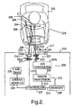
- OPS system 220 is positioned proximate to air bag module 229, which is located within dashboard 212.
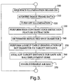
- System 220 includes light emitter 221, which is coupled to controller 227 by communication bus 213 and contains multiple light sources 221a that, when activated (step 300 of Fig. 3), emit infrared (“IR”) light beams 206 to illuminate occupant area 218 between OPS system 220 and vehicle seat 202.
- IR infrared
- Emitter 221 also includes lens system 216, which may include aspheric element 222a for concentrating light beams 206 and convex lens 222 for focusing light beams 206 on vehicle occupant, or target, 204.
- Light beams 206 are directed towards occupant area 218 in a manner to provide sufficient coverage of the air bag deployment zone. Light beams 206 illuminate spots 208 on vehicle target 204 and are reflected as reflected light beams 210.
- OPS system 220 also includes a light receiver.
- the light receiver includes imaging sensor 223 used to acquire images.
- Imaging sensor 223 may include, for example, complementary metal oxide semiconductor (“CMOS”) image sensors and charge-coupled device (“CCD”) image sensors. Such sensors are manufactured by Eastman Kodak Company of New Jersey.
- Imaging sensor 223 includes lens system 217, which may include IR filter 219, aspheric element 219a for imaging reflected light beams 210 to produce imaged spots 211, and convex lens 224 for focusing and magnifying imaged spots 211 onto photosensitive device 225.
- CMOS complementary metal oxide semiconductor
- CCD charge-coupled device
- imaging sensor 223 acquires an image of occupant area 218 (step 310).
- Photosensitive device 225 includes multiple photodiodes that convert light to electrons. The number of electrons produced is a function of the wavelength and the intensity of reflected light beams 210 striking photosensitive device 225. Electrons are collected in a holding region (not shown) until light sources 221a are inactivated and the illumination period is finished (step 320), upon which time reflected light beams 210 are either converted into a voltage (e.g., CMOS processors) or transferred to a metering register (e.g., CCD sensors) and subsequently converted to a voltage. The measured voltage is passed through analog-to-digital converter circuitry 225a of photosensitive device 225, which then forms a digital electronic representation of the scene imaged by imaging sensor 223.
- CMOS processors e.g., CMOS processors
- a metering register e.g., CCD sensors
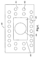
- OPS system 420 is shown in Fig. 4.
- image sensor 423 is integrated with light sources 422.
- Light emitter 421 contains a plurality of light sources 422, which surround image sensor 423.
- light sources 422 are arranged in a collimated array.
- Light sources 422 may include, for example, infrared light sources and/or sensor light sources.
- Image sensor 423 includes focusing lens 424 and photodiode 425, upon which reflected spots 211 (Fig. 2) produced by reflected light beams 210 are imaged.
- Image sensor 423 may be capable of capturing images at a rate of anywhere between 30 to 1000 frames per second.
- light sources 422 may be arranged in a different relationship with respect to image sensor 423, and image sensor 423 and light emitter 421 may be positioned separately on dashboard 212 of the vehicle.
- object proximity sensor system 520 is positioned in object proximity sensor system plane 523 and includes light sources 521 and focusing lens 524.
- Light sources 521 are positioned proximately to and above and below lens 524 and may emit infrared light beams 506.
- target 504 which is a first distance ("D1") away from object proximity sensor plane 523
- D1 a first distance
- Magnified reflected light beam 511a forms magnified imaged spot 512a on the photodiode.
- the diameter of imaged spot 512a can then be determined to find out D1.
- light beam 506 emitted from light source 521 hits target 524, which is a second distance (“D2") away from object proximity sensor system plane 523, it creates illumination spot 508b and then reflects off target 524 and is magnified by lens 524 onto a photodiode 525a positioned in photodiode plane 525.
- Magnified reflected light beam 511b forms magnified imaged spot 512b on the photodiode.
- the diameter of imaged spot 512b may then be determined to find out D2.
- communication bus 213 couples photosensitive device 225 to image processor 226.
- the image captured by imaging sensor 223 is output as video signals to image processor 226 and subsequently processed.
- image processor 226 is an Application Specific Integrated Circuit ("ASIC").
- ASIC Application Specific Integrated Circuit
- Image 600 is illustrated in Fig. 6A.
- Image 600 displays occupant area 618 of a vehicle that is captured in image 600 by an imaging sensor.
- Image 600 portrays vehicle occupant 604 sitting in vehicle seat 602.
- Imaged spots 600 also appear on image 600.
- Imaged spots 608 are the spots produced by light beams that are (1) emitted by a light emitter's plurality of light sources to illuminate the air bag deployment zone of occupant area 618, (2) reflected off of either occupant 604, seat 602 or other object in the occupant area; and (3) received and captured by an imaging sensor to render image 600.
- the size of imaged spots 608 on image 600 is a function of the non-linear magnification of the imaging sensor's lens system, or optics.
- the distance of occupant 604 from the imaging sensor may be directly determined from the relative change in the magnification of imaged spots 608. Because the relationship between the size of imaged spots 608 and occupant's 604 distance is a fundamental aspect of optics, as long as the sizes of imaged spots 608 are known, the distance between occupant 604 and the imaging sensor can be determined. As is known in the art, the relationship between size and distance can be expressed using the following standard mathematic equations:
- imaged spots 608 may be distorted and, hence, not a perfect circle. Therefore, in order to ascertain an accurate diameter for imaged spots 608 so that the distance of occupant 604 from the imaging sensor may be determined, it may be necessary to compensate for the distortion by performing image processing functions on image 600.
- image processing functions Well known processing operations in the art of digital image processing may be performed on image 600 to more clearly determine the edges of imaged spots 608 for measurement, including, but not limited to, image feature extraction (step 330), the Sobel operator for edge enhancement, and filtering to remove noise from image 500.
- Image processor 226 (Fig. 2) may be capable of executing a set of preprogrammed instructions (perhaps stored in memory 228) necessary to process image 600.
- image processor 226 may be programmed to carry out a feature extraction technique. After receiving image 600 (Fig. 5), image processor 226, using known algorithms and methods, may extract a feature set from image 600 to pixel accuracy. The feature set may be the outlines or edges of imaged spots 608. Image processor 226 may then transmit this data to controller 227 for use in calculating the diameters of each imaged spot 608 (step 340).
- image processor 226 may include a known edge extracting device which performs a filtering treatment to image 600 that may use a spatial filter to emphasize, or extract, pixels from image 600 whose brightness steeply changes. Consequently, the edges of imaged spots 608 may be more clearly obtained, and the diameters of imaged spots 608 more easily determined.
- Memory 228 of OPS system 220 may be used to store look-up tables containing calculated data that shows the relationship between the diameters of imaged spots 608 and the distance that vehicle occupant 604 is from light emitter 221.
- the data in the look-up tables may be adjusted for various application parameters, e.g., actual lens magnification versus theoretical lens magnification, actual light source angle and location versus theoretical light source angle and location, etc.
- the image sensor is calibrated before use so that these adjustments may be made.
- a look-up table may contain a plurality of spot diameter data values, e.g., 2 mm, 4 mm, 6 mm, ... , 10 mm, etc.
- the look-up table may also contain a plurality of vehicle occupant distance data values, e.g., 400 mm, 390 mm, 380 mm, ... , 100 mm, etc.
- Each of the spot diameter data values may correspond to a vehicle occupant distance data value. This relationship may be shown in terms of a relative diameter and pixels.
- imaging sensor 223 may be a 640 X 480 pixel device that is 5 mm x 4 mm and has 7.5 um x 7.5 um pixels. Accordingly, if the vehicle occupant distance data value is 100 mm (i.e., target 204 is 100 mm from light emitter 221), the spot diameter data value is 100 pixels.
- the spot diameter data vale is 50 pixels.
- the spot diameter data value is 33 pixels, and if the vehicle occupant distance data value is 400 mm, the spot diameter data value is 25 pixels.
- the look-up table may be used to predict the distance that vehicle occupant 604 is from light emitter 221.
- FIG. 7 depicts the theoretical magnification of IR light beams that reflect off vehicle occupant 604 as occupant 604 moves closer to the imaging sensor.
- theoretical curve 710 indicates that as the distance between vehicle occupant 604 and the imaging sensor decreases, the magnification of imaged spots 608 increases.
- data points 712, 714, 716 were measured in a lab environment using an IR light emitting source and an imaging sensor. The imaged spots produced in the images captured by the image sensor were viewed with a commercial photo editor so that the diameters of the imaged spots could be measured. As may be seen in Fig.
- controller 227 interpolates the look-up table stored in memory 228 to determine distance D between vehicle target 204 and light emitter 221 (step 350 of Fig. 3). The determination of distance D is done at the frame rate of imaging sensor 223 and provides a high response rate to any movement of target 204. Once distance D has been determined, controller 227 may execute preprogrammed instructions to determine whether vehicle occupant 604 is within the vehicle's safe air bag deployment zone. Base on the position of vehicle occupant 604, controller 227 can determine whether to enable/disable air bag 230 (step 370).
- controller 227 Before making the determination to enable/disable air bag 230, however, it may first be necessary for controller 227 to analyze distance D as the distance is calculated in order to interpret target 204 and classify target 204 in seat 202 as a FFIS, a RFIS, an OOP small child or an adult, or an unoccupied seat. Upon classification of target 204, tracking and OOP testing may be performed as well.
- the tracking function involves identifying the head/torso portion of target 204 (if target 204 is classified as a child or an adult) based on distance D, identifying a grouping of light beams 206 corresponding to that portion, and updating distance D using the identified grouping of light beams 206 at a very fast rate so that the position of the head/torso can be tracked relative to a predefined OOP threshold, i.e., a predefined distance from the point of deployment of air bag 230.
- a predefined OOP threshold i.e., a predefined distance from the point of deployment of air bag 230.
Landscapes
- Engineering & Computer Science (AREA)
- Computer Vision & Pattern Recognition (AREA)
- Mechanical Engineering (AREA)
- Air Bags (AREA)
- Measurement Of Optical Distance (AREA)
- Length Measuring Devices By Optical Means (AREA)
Applications Claiming Priority (2)
| Application Number | Priority Date | Filing Date | Title |
|---|---|---|---|
| US753839 | 1985-07-11 | ||
| US10/753,839 US20050151053A1 (en) | 2004-01-08 | 2004-01-08 | Infrared proximity sensor for air bag safety |
Publications (2)
| Publication Number | Publication Date |
|---|---|
| EP1552988A2 true EP1552988A2 (de) | 2005-07-13 |
| EP1552988A3 EP1552988A3 (de) | 2007-04-18 |
Family
ID=34592586
Family Applications (1)
| Application Number | Title | Priority Date | Filing Date |
|---|---|---|---|
| EP04078513A Withdrawn EP1552988A3 (de) | 2004-01-08 | 2004-12-23 | Infrarotnäherungssensor für Airbag-Sicherheit |
Country Status (2)
| Country | Link |
|---|---|
| US (1) | US20050151053A1 (de) |
| EP (1) | EP1552988A3 (de) |
Cited By (4)
| Publication number | Priority date | Publication date | Assignee | Title |
|---|---|---|---|---|
| US9024810B2 (en) | 2009-01-27 | 2015-05-05 | Xyz Interactive Technologies Inc. | Method and apparatus for ranging finding, orienting, and/or positioning of single and/or multiple devices |
| GB2553644A (en) * | 2016-07-06 | 2018-03-14 | Ford Global Tech Llc | Vehicle dashboard safety features |
| US10320384B2 (en) | 2014-06-02 | 2019-06-11 | Xyz Interactive Technologies Inc. | Touch-less switching |
| US10452157B2 (en) | 2014-10-07 | 2019-10-22 | Xyz Interactive Technologies Inc. | Device and method for orientation and positioning |
Families Citing this family (10)
| Publication number | Priority date | Publication date | Assignee | Title |
|---|---|---|---|---|
| US20080023946A1 (en) * | 2004-01-30 | 2008-01-31 | Daimlerchrysler Ag | Driver Restraining System in a Motor Vehicle |
| US7448251B2 (en) * | 2005-01-06 | 2008-11-11 | Honda Motor Co., Ltd. | Method for preparing a motor vehicle for a crash test |
| JP4389812B2 (ja) * | 2005-03-03 | 2009-12-24 | 株式会社デンソーウェーブ | 光学情報読取装置 |
| US20080136227A1 (en) * | 2006-12-11 | 2008-06-12 | 3M Innovative Properties Company | Vehicle seat sensor assembly |
| US7810992B2 (en) * | 2007-04-09 | 2010-10-12 | Avita Corporation | Non-contact temperature-measuring device and the method thereof |
| KR101048768B1 (ko) * | 2009-06-10 | 2011-07-15 | (주)실리콘화일 | 조도, 근접도 및 색온도 측정이 가능한 이미지센서 |
| US20110133755A1 (en) * | 2009-12-08 | 2011-06-09 | Delphi Technologies, Inc. | System and Method of Occupant Detection with a Resonant Frequency |
| US9744929B2 (en) | 2015-11-25 | 2017-08-29 | Ford Global Technologies, Llc | Front passenger knee bolster deployment control |
| US9604588B1 (en) | 2015-11-25 | 2017-03-28 | Ford Global Technologies, Llc | Rear row knee bolster deployment control |
| US9834165B2 (en) | 2015-11-25 | 2017-12-05 | Ford Global Technologies, Llc | Driver knee bolster deployment control |
Citations (1)
| Publication number | Priority date | Publication date | Assignee | Title |
|---|---|---|---|---|
| US6298311B1 (en) | 1999-03-01 | 2001-10-02 | Delphi Technologies, Inc. | Infrared occupant position detection system and method for a motor vehicle |
Family Cites Families (10)
| Publication number | Priority date | Publication date | Assignee | Title |
|---|---|---|---|---|
| US6442465B2 (en) * | 1992-05-05 | 2002-08-27 | Automotive Technologies International, Inc. | Vehicular component control systems and methods |
| US5479011A (en) * | 1992-12-18 | 1995-12-26 | Spectra-Physics Scanning Systems, Inc. | Variable focus optical system for data reading |
| US5446661A (en) * | 1993-04-15 | 1995-08-29 | Automotive Systems Laboratory, Inc. | Adjustable crash discrimination system with occupant position detection |
| DE4400664C2 (de) * | 1994-01-12 | 1995-11-16 | Spies Martin Dipl Ing Fh | Vorrichtung zur Erkennung der Sitzbelegung in Fahrzeugen etc. |
| DE19637108B4 (de) * | 1996-09-12 | 2005-10-27 | Adam Opel Ag | Insassenschutzsystem für Kraftfahrzeuge sowie ein Verfahren zur kontinuierlichen Überwachung der Sitzposition des Insassen |
| US6697103B1 (en) * | 1998-03-19 | 2004-02-24 | Dennis Sunga Fernandez | Integrated network for monitoring remote objects |
| US6323487B1 (en) * | 1999-01-26 | 2001-11-27 | Delphi Technologies, Inc. | IR optical position sensor system |
| US6875993B2 (en) * | 2001-04-12 | 2005-04-05 | Honeywell International Inc. | Systems and methods for optically detecting and identifying objects in an environment |
| US6781676B2 (en) * | 2002-03-22 | 2004-08-24 | Trw Inc. | Structured lighting detection of vehicle occupant type and position |
| JP2004053324A (ja) * | 2002-07-17 | 2004-02-19 | Denso Corp | 自動車用衝突安全制御装置 |
-
2004
- 2004-01-08 US US10/753,839 patent/US20050151053A1/en not_active Abandoned
- 2004-12-23 EP EP04078513A patent/EP1552988A3/de not_active Withdrawn
Patent Citations (1)
| Publication number | Priority date | Publication date | Assignee | Title |
|---|---|---|---|---|
| US6298311B1 (en) | 1999-03-01 | 2001-10-02 | Delphi Technologies, Inc. | Infrared occupant position detection system and method for a motor vehicle |
Cited By (7)
| Publication number | Priority date | Publication date | Assignee | Title |
|---|---|---|---|---|
| US9024810B2 (en) | 2009-01-27 | 2015-05-05 | Xyz Interactive Technologies Inc. | Method and apparatus for ranging finding, orienting, and/or positioning of single and/or multiple devices |
| US10320384B2 (en) | 2014-06-02 | 2019-06-11 | Xyz Interactive Technologies Inc. | Touch-less switching |
| US11362657B2 (en) | 2014-06-02 | 2022-06-14 | Xyz Interactive Technologies Inc. | Touch-less switching |
| US10452157B2 (en) | 2014-10-07 | 2019-10-22 | Xyz Interactive Technologies Inc. | Device and method for orientation and positioning |
| US10996768B2 (en) | 2014-10-07 | 2021-05-04 | Xyz Interactive Technologies Inc. | Device and method for orientation and positioning |
| GB2553644A (en) * | 2016-07-06 | 2018-03-14 | Ford Global Tech Llc | Vehicle dashboard safety features |
| US10676058B2 (en) | 2016-07-06 | 2020-06-09 | Ford Global Technologies, Llc | Vehicle dashboard safety features |
Also Published As
| Publication number | Publication date |
|---|---|
| EP1552988A3 (de) | 2007-04-18 |
| US20050151053A1 (en) | 2005-07-14 |
Similar Documents
| Publication | Publication Date | Title |
|---|---|---|
| US6772057B2 (en) | Vehicular monitoring systems using image processing | |
| US6507779B2 (en) | Vehicle rear seat monitor | |
| US6442465B2 (en) | Vehicular component control systems and methods | |
| US6856873B2 (en) | Vehicular monitoring systems using image processing | |
| US6553296B2 (en) | Vehicular occupant detection arrangements | |
| US6324453B1 (en) | Methods for determining the identification and position of and monitoring objects in a vehicle | |
| US6005958A (en) | Occupant type and position detection system | |
| US6757009B1 (en) | Apparatus for detecting the presence of an occupant in a motor vehicle | |
| US7607509B2 (en) | Safety device for a vehicle | |
| US6480616B1 (en) | Status-of-use decision device for a seat | |
| US8081800B2 (en) | Detection device of vehicle interior condition | |
| US8059867B2 (en) | Detection system, informing system, actuation system and vehicle | |
| Hsu et al. | Performance of a time-of-flight range camera for intelligent vehicle safety applications | |
| EP1552988A2 (de) | Infrarotnäherungssensor für Airbag-Sicherheit | |
| KR100630842B1 (ko) | 스테레오 영상 정합을 이용한 자동차의 탑승자 자세 판별시스템 및 그 방법 | |
| US10131309B2 (en) | Apparatus and method for controlling airbag | |
| US20070289799A1 (en) | Vehicle occupant detecting system | |
| US20040220705A1 (en) | Visual classification and posture estimation of multiple vehicle occupants | |
| US6781676B2 (en) | Structured lighting detection of vehicle occupant type and position | |
| KR20030082550A (ko) | 차량 내 대상을 감지하기 위한 장치 및 방법 | |
| JP2004503759A (ja) | 乗員センサ | |
| US6678598B1 (en) | Device and method for seat supervision in motor vehicles | |
| EP1792788A1 (de) | Abtastendes Laserlinienmessgerät für einen Fahrzeuginsassen | |
| US6947575B2 (en) | Apparatus and method for determining vehicle occupant characteristic utilizing imaging with provided light | |
| EP1800964B1 (de) | Verfahren zur Tiefenschätzung von einer Einzelkamera aus |
Legal Events
| Date | Code | Title | Description |
|---|---|---|---|
| PUAI | Public reference made under article 153(3) epc to a published international application that has entered the european phase |
Free format text: ORIGINAL CODE: 0009012 |
|
| AK | Designated contracting states |
Kind code of ref document: A2 Designated state(s): AT BE BG CH CY CZ DE DK EE ES FI FR GB GR HU IE IS IT LI LT LU MC NL PL PT RO SE SI SK TR |
|
| AX | Request for extension of the european patent |
Extension state: AL BA HR LV MK YU |
|
| PUAL | Search report despatched |
Free format text: ORIGINAL CODE: 0009013 |
|
| AK | Designated contracting states |
Kind code of ref document: A3 Designated state(s): AT BE BG CH CY CZ DE DK EE ES FI FR GB GR HU IE IS IT LI LT LU MC NL PL PT RO SE SI SK TR |
|
| AX | Request for extension of the european patent |
Extension state: AL BA HR LV MK YU |
|
| 17P | Request for examination filed |
Effective date: 20071018 |
|
| AKX | Designation fees paid |
Designated state(s): AT BE BG CH CY CZ DE DK EE ES FI FR GB GR HU IE IS IT LI LT LU MC NL PL PT RO SE SI SK TR |
|
| GRAP | Despatch of communication of intention to grant a patent |
Free format text: ORIGINAL CODE: EPIDOSNIGR1 |
|
| STAA | Information on the status of an ep patent application or granted ep patent |
Free format text: STATUS: THE APPLICATION IS DEEMED TO BE WITHDRAWN |
|
| 18D | Application deemed to be withdrawn |
Effective date: 20110621 |