EP1552260B1 - Capteur de pression et fabrication de celui-ci - Google Patents
Capteur de pression et fabrication de celui-ci Download PDFInfo
- Publication number
- EP1552260B1 EP1552260B1 EP03751047A EP03751047A EP1552260B1 EP 1552260 B1 EP1552260 B1 EP 1552260B1 EP 03751047 A EP03751047 A EP 03751047A EP 03751047 A EP03751047 A EP 03751047A EP 1552260 B1 EP1552260 B1 EP 1552260B1
- Authority
- EP
- European Patent Office
- Prior art keywords
- sensor
- diaphragm
- plate
- sensor plate
- pressure
- Prior art date
- Legal status (The legal status is an assumption and is not a legal conclusion. Google has not performed a legal analysis and makes no representation as to the accuracy of the status listed.)
- Expired - Lifetime
Links
Images


Classifications
-
- G—PHYSICS
- G01—MEASURING; TESTING
- G01L—MEASURING FORCE, STRESS, TORQUE, WORK, MECHANICAL POWER, MECHANICAL EFFICIENCY, OR FLUID PRESSURE
- G01L15/00—Devices or apparatus for measuring two or more fluid pressure values simultaneously
-
- G—PHYSICS
- G01—MEASURING; TESTING
- G01L—MEASURING FORCE, STRESS, TORQUE, WORK, MECHANICAL POWER, MECHANICAL EFFICIENCY, OR FLUID PRESSURE
- G01L19/00—Details of, or accessories for, apparatus for measuring steady or quasi-steady pressure of a fluent medium insofar as such details or accessories are not special to particular types of pressure gauges
- G01L19/14—Housings
- G01L19/148—Details about the circuit board integration, e.g. integrated with the diaphragm surface or encapsulation
-
- G—PHYSICS
- G01—MEASURING; TESTING
- G01L—MEASURING FORCE, STRESS, TORQUE, WORK, MECHANICAL POWER, MECHANICAL EFFICIENCY, OR FLUID PRESSURE
- G01L9/00—Measuring steady of quasi-steady pressure of fluid or fluent solid material by electric or magnetic pressure-sensitive elements; Transmitting or indicating the displacement of mechanical pressure-sensitive elements, used to measure the steady or quasi-steady pressure of a fluid or fluent solid material, by electric or magnetic means
- G01L9/0041—Transmitting or indicating the displacement of flexible diaphragms
- G01L9/0051—Transmitting or indicating the displacement of flexible diaphragms using variations in ohmic resistance
- G01L9/0052—Transmitting or indicating the displacement of flexible diaphragms using variations in ohmic resistance of piezoresistive elements
- G01L9/0055—Transmitting or indicating the displacement of flexible diaphragms using variations in ohmic resistance of piezoresistive elements bonded on a diaphragm
Definitions
- the present invention relates to a pressure sensor and to a method of producing a pressure sensor.
- US-B-6318183 discloses a multiple element sensor for sensing pressure.
- a substrate has a rectangular diaphragm portion on which are disposed first, second, third and fourth sensing elements.
- Each sensing element is a strain gauge.
- the diaphragm is flexible and flexes when subjected to pressure.
- Each of the sensing elements is adapted to output a signal proportional to the deflection.
- Each sensing element is disposed proximate a respective edge of the diaphragm.
- Each sensing element has respective output terminals and is also connected to respective power supply terminals.
- Each of the output terminals for the sensing elements provides a signal indicative of sensed pressure and the terminals are connected to a combining circuit.
- the combining circuit outputs signals indicative of pressure applied to one or more of the sensing elements.
- the different sensing elements have different respective pressure sensing ranges so that the pressure sensor has a wide pressure sensing range, as a result of the provision of a plurality of sensing elements on the same diaphragm, yet the sensor has good sensitivity within the range of each sensing element.
- the multiple element sensor for sensing pressure disclosed in US-B-6318183 does not address the problem of providing a pressure sensor which can independently sense a number of discrete pressures from different sources. Furthermore, the sensor has a large number of electrical connections, which can reduce the reliability of the device.
- US-A-2001/0049965 discloses an electronic control apparatus, contained within a housing and a cover, which comprises a printed circuit board with both electronic components and at least one pressure sensor in the form of an integrated circuit (IC).
- the printed circuit board contains the pressure sensor, which is disclosed as being designed as a conventional component or in the form of a surface mounted component that is soldered directly to the printed circuit board, which in turn is mounted to the cover.
- a “snorkel” consists of a tubular lower part and a pot-shaped upper part, the latter having an edge which is sealed to the printed circuit board by means of a sealing ring so that the upper part encloses the pressure sensor.
- the snorkel channels a pressure medium to be measured to the pressure sensor.
- a pressure equalisation chamber is configured on the opposite side of the printed circuit board in relation to the snorkel, which has the same cross-sectional surface area as the upper part of the snorkel.
- a pressure equalisation bore, penetrating the printed circuit board at the location of the pressure sensor, enables the aeration of the pressure equalisation chamber.
- a heat sink type of printed circuit board is mounted directly to the interior surface of the cover for the housing. The provides rigidity to a heat sink printed circuit board for withstanding the applied pressure medium applied by the snorkel.
- the electronic control apparatus incorporating at least one pressure sensor disclosed in US-A-2001/0049965 is mechanically complicated and physically bulky. It only discloses sensors mounted onto a printed circuit board (PCB), typically composed of epoxy resin or another polymer, but the PCB may suffer from the problem of poor corrosion resistance in certain environments. There is also a risk of short circuit due to a potential exposure of electrical connections to an electrically conducting pressure medium.
- PCB printed circuit board
- the prior art is also known to provide a pressure sensor which is configured to sense a number of discrete pressures.
- a single manifold block is provided having a plurality of ports therein, and a respective individual sensor is threadably received in each port.
- Each sensor is connected by its respective electrical wire interconnects to a remote printed circuit board which provides the sensor's output.
- This known arrangement is physically bulky, has relatively high cost and has low reliability as a result of the large number of electrical connectors required.
- WO-A-97/00433 disclose a pressure sensor plate in which the sensor plate has a plurality of integral measuring diaphragms. For each diaphragm, strain gauges are applied on the respective diaphragm, and conductor tracks interconnect them to form a Wheatstone bridge, having terminal contacts.
- the terminal contacts associated with respective measuring diaphragms are connected to a common evaluation circuit by thick-wire bonds, specifically by aluminium wires connected to the terminal contacts by friction welding. Again, such electrical connections can reduce the reliability of the device.
- US-A-5421956 discloses a method of fabricating an integrated pressure sensor.
- a silicon wafer has a plurality of thin diaphragms formed therein.
- the wafer is applied to a glass seat and the wafer is cut through with grooves that extend into the glass seat.
- the grooves define the boundaries of the chips, which are separated from each other by the grooves. Terminal plates of the sensor are connected to the chip by bonding wires.
- bonding wires are required, which is disadvantageous and can affect reliability, even though a complicated testing protocol is employed to test that each chip is operative.
- the use of a silicon wafer can limit the applications of the device, particularly when the pressure gauge is to be used in particular environments containing potential contaminants for the silicon wafer.
- US-A-4790192 discloses silicon side by side coplanar pressure sensors.
- the sensors include a complicated multi-component stack of layers enclosed within a housing.
- US-A-3930412 discloses electrically scanned pressure transducer configurations. Pressure sensors associated with respective pressure ports are connected together by wires to a printed circuit board. This reduces device reliability.
- the present invention aims at least partially to solve the aforementioned problems in the prior art, and more particularly to provide a pressure sensor permitting compatibility between the materials of the pressure sensor and the pressure medium, low cost and suitability for high pressures.
- the present invention provides a pressure sensor comprising a sensor plate defining a plurality of diaphragms therein, and an electrical circuit on the sensor plate, the electrical circuit including a plurality of sensor elements, each sensor element being located above a respective diaphragm and arranged to detect a deflection of the diaphragm, and a manifold defining therein a plurality of ports for receiving pressurised fluid, the sensor plate covering an end of each of the plurality of ports, with each diaphragm being adjacent to a respective one of the ports for detecting fluid pressure changes in the respective port, and wherein the electrical circuit is a thick-film printed circuit, that has been formed in situ on the sensor plate, the sensor elements being formed by printing on a substrate of the electrical circuit, the electrical circuit and the sensor plate being integrated to form a monolithic plate, and the adjacent surfaces of the sensor plate and the manifold are hermetically sealed together.
- the present invention provides a method of producing a pressure sensor, the method comprising the steps of:
- a pressure sensor designated generally as 2, in accordance with a first embodiment of the present invention comprises a sensor plate 4 disposed on a manifold block 6.
- a plurality of pressure ports 8 are defined in the manifold block 6.
- Each pressure port 8 at one end terminates in an opening 10 adjacent to a respective diaphragm portion 12 of the sensor plate 4.
- the pressure port 8 is connected to a respective source (not shown) of hydraulic or pneumatic pressure which is to be measured by the pressure sensor.
- the pressure sensor can detect fluid pressure from a liquid or gas.
- the adjacent surfaces 14,16 of the sensor plate 4 and the manifold block 6 are hermetically sealed together.
- a diaphragm 18 is defined by the sensor plate 4 at the respective end 10 of each pressure port 8.
- the diaphragm 18 is defined by a cavity 20 formed in the sensor plate 4 above the end 10 of the respective port 8.
- the cavity 20 may be formed by etching, for example mechanical etching or machining, laser etching, wet chemical etching, either isotropic or anisotropic, dry reactive ion etching, ion beam etching or plasma etching.
- the diaphragm 18 is defined by a reduced thickness region of the sensor plate 4 which overlies a respective pressure port 8.
- the cavity 20 extends laterally with respect to edges of the respective pressure port 8 to define cutaway portions 22 of the sensor plate 4 above respective associated shoulder portions 24 of the manifold block 6.
- the surface area of the diaphragm 18 is may be greater than (as in Figures 1 to 3 ), smaller than or the same size as the cross-sectional area of the pressure port 8.
- a printed electrical circuit 28 is disposed on that surface 26 of the sensor plate 4 which is remote from the surface 14 adjacent to the manifold block 6, a printed electrical circuit 28 is disposed.
- the printed circuit 28 has been formed on the sensor plate 4 so as to form an integral monolithic structure.
- the printed circuit 28 includes a plurality of sensor elements in the form of strain gauges 30, each formed in the printed circuit 28 above a respective diaphragm 18, and electrical interconnects 32, which connect the respective strain gauges 30 to respective integrated circuits 34 formed in the printed circuit 28.
- the integrated circuits 34 are attached as prefabricated chips on the printed circuit 28.
- the printed circuit 28 is formed in situ on the sensor plate 4 by, for example, printing, typically screen printing, various electrically conductive, insulating and resistive layers onto the surface 26 of the sensor plate 4.
- This when combined with surface mounted components, forms what is known in the art as a "thick-film circuit" on the sensor plate 4, thereby to form a monolithic substrate.
- This combines both the diaphragms 18 and the strain gauges 30, and also the associated circuitry 32,34 for compensation networks, comprising temperature compensating and bridge balance resistors, to supply power to the strain gauges 30, and to provide signal outputs, represented schematically by the output 36 in the Figure 1 .
- the circuitry of the thick film circuit conducts the signals from the strain sensor resistors to the output stage, which thereafter may be accessed via an analogue and/or digital communications bus.
- the printed circuit 28 thereby forms a functional element of the pressure sensor.
- the sensor plate 4 is electrically conductive, in particular being composed of a metal such as stainless steel, and is accordingly initially screen printed with an insulating layer 38 upon which the thick-film printed circuit 28 is subsequently fabricated as described above.
- the strain gauges 30 preferably comprise thick-film piezoelectric resistors which have been screen printed onto the insulating layer 38.
- the complementary circuitry 32,42 is also screen printed onto the insulating layer 38.
- the additional screen printed insulating layer can be omitted, and the strain sensing resistors of the strain gauges can be printed directly onto the sensor plate.
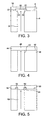
- FIG. 4 A modified assembly of the sensor plate and the manifold block is shown in Figure 4 .
- no cavity has been formed in the sensor plate 44 by etching and accordingly the surface 42 of the sensor plate 44 adjacent the manifold block 44, and defining the input side of the diaphragm 48, is planar.
- the surface area of each diaphragm 48 is therefore defined by the cross-sectional area of the corresponding pressure port 50.
- FIG. 5 A further modification of the sensor plate and manifold block assembly is illustrated in Figure 5 .
- an annular cavity 52 has been etched, as described above, in the surface 54 of the sensor plate 56 which is adjacent to the manifold block 58 so as to define an annular diaphragm 60 in the sensor plate 56 associated with the respective pressure ports 62.
- the annular diaphragm 60 is typically coaxial with the pressure port 62.
- the surface area of the diaphragm 60 is larger than the cross-sectional area of the corresponding pressure port 62.
- FIG. 6 shows a pressure sensor in accordance with a further embodiment of the present invention.
- any deflection of the diaphragm resulting from fluid pressure in the respective pressure port is detected using an inductive or capacitative technique rather by using a sensing element in the form of a strain gauge having a strain sensing resistor.
- each diaphragm 70 is defined by forming a cavity 72, for example by etching as described above, in the surface 74 of the sensor plate 76 which is remote from the manifold block 78.
- An insulating substrate 78 supporting a printed circuit 80 extends over and covers each cavity 72.
- the printed circuit 80 may have been formed by printing so as to form a thick film circuit as described above.
- a sensing element 82 comprising a printed capacitor plate or a mounted or printed inductive coil is on the underside of the insulating substrate 78 in the cavity 72 thereby to define an air gap 84 between the diaphragm 70 and the sensing element 82.
- the diaphragm 70 has an inverted structure compared to the diaphragm of the embodiment of Figures 1 to 3 in the sense that a cavity 72 is formed in the surface 74 of the sensor plate 76 remote from the pressure port 86 rather than in the surface of the sensor plate communicating with the pressure port.
- FIG. 7 A yet further embodiment of a pressure sensor in accordance with the present invention is illustrated in Figure 7 .
- the sensor plate comprises a laminated structure to form an air gap rather than a single plate having an etched cavity.
- the sensor plate 90 comprises a substrate layer 92 which has an outer surface 94 partially defining a diaphragm-forming portion 96 and partially sealed to the manifold block 98.
- a patterned layer 100 is laminated over the substrate layer 92.
- the patterned layer 100 includes an opening 102, in this embodiment an annular opening 102 and a central portion 103, which is registered with a central part 104 of a corresponding diaphragm-forming portion 96 of the substrate layer 92, thereby to define a diaphragm 106 over the associated pressure port 108.
- the adjacent surfaces of the substrate layer 92, patterned layer 100 and insulating substrate 110 are fixed together, for example by adhesive, or, when the layers are of metal, by soldering or brazing 113, except above the central portion 103 of the patterned layer 100 where an air gap 114 is provided between the central portion 103 and the insulating substrate 110.
- a capacitor plate or inductive coil (not shown) is mounted or printed onto the underside of the insulating substrate 110 to sense the thickness of the air gap 114, thereby producing an output signal indicative of the deflection of the diaphragm 106 as a result of fluid pressure in the respective pressure port 108.
- the sensor plate may be configured to have different pressure ranges for detection by the sensor elements by changing at least one of the aperture of the pressure port, the respective diaphragm area, or the thickness of the substrate and/or the diaphragm.
- the diaphragm may have a constant thickness across its surface area (i.e. a simple diaphragm) as shown in Figures 1 to 3 and 4 or alternatively may be annular, having a thickened central portion, as shown in Figures 5 , 6 and 7 .
- the diaphragm may be any geometric shape such as square, circular, rectangular or hexagonal.
- the sensor plate may comprise a single plate, which may have had cavities found therein, or a laminate structure of which one or more plates may be shaped to form cavities in the laminate.
- the laminated structure may be suitable for any sensing technique i.e. strain gauge, inductive, or capacitive
- the diaphragms and associated sensing elements may be sited over the individual pressure ports in the manifold block in a linear or matrix fashion to provide multiple-point pressure sensing using a monolithic substrate.
- a plurality of sensing elements may be associated with each diaphragm, for example two sensing elements for each pressure port, each aligned with a respective lateral edge of the respective pressure port.
- the sensor elements may alternatively comprise a resonant, tunnelling current or optical detector.
- the pressure sensor of the invention can be employed to sense a plurality of discrete pressures, and in particular pressures which may be encountered by corrosive, ionising or non-ionising media.
- the pressure sensor of the present invention has particular utility for sensing a plurality of pneumatic pressures which are present in a pneumatic brake system for a vehicle, for example a truck.
- the pressure sensor of the present invention provides a pressure sensor which has low unit cost, small physical volume and high reliability. Since a plurality of pressure sensing elements are incorporated into a common monolithic plate, which integrates together both the diaphragms, the sensing elements and the electronic circuitry for generating output signals, the pressure sensor of the present invention is physically compact and can be produced at relatively low cost, for example by using known screen printing techniques for producing thick-film circuits. Furthermore, by forming a thick film printed circuit integral with the sensor plate, the number of electrical connections between the sensing elements and the output stage can be reduced as compared to known pressure sensors, for example the pressure sensor known from US-B-6318183 . This reduction in the number of electrical connections can greatly increase the reliability of the pressure sensor.
- the corrosion resistance can be improved. Furthermore, with the present invention there is a reduced risk of short circuit when employed in an electrical conducting pressure medium.
Abstract
Claims (10)
- Capteur de pression (2) comprenant une plaque de détection (4) définissant une pluralité de diaphragmes (18) dedans, et un circuit électrique (28) sur la plaque de détection (4), le circuit électrique (28) comportant une pluralité d'éléments de détection (30), chaque élément de détection (30) étant situé au-dessus d'un diaphragme respectif (18) et agencé pour détecter une déviation du diaphragme (18), et un collecteur (6) définissant dedans une pluralité d'orifices (8) pour recevoir un fluide sous pression, la plaque de détection (4) couvrant une extrémité de chacun de la pluralité d'orifices (8), avec chaque diaphragme (18) étant adjacent à un orifice respectif des orifices (8) pour détecter des changements de pression de fluide dans l'orifice respectif (8), et où le circuit électrique (28) est un circuit imprimé à couches épaisses, qui a été formé in situ sur la plaque de détection (4), les éléments de détection (30) étant formés par impression sur un substrat du circuit électrique (28), le circuit électrique (28) et la plaque de détection (4) étant intégrés pour former une plaque monolithique, et les surfaces adjacentes de la plaque de détection (4) et le collecteur sont hermétiquement scellés entre eux.
- Capteur de pression selon la revendication 1 dans lequel la plaque de détection (4) comprend une structure stratifiée, avec au moins une couche du stratifié étant conformée pour obtenir au moins une cavité (20) dans la plaque de détection (4) adjacente à un diaphragme respectif (18).
- Capteur de pression selon la revendication 1 ou 2, dans lequel les éléments de détection (30) sont des extensomètres qui sont formés sur une surface de la plaque de détection (4).
- Capteur de pression selon la revendication 3, dans lequel le diaphragme (18) comprend une partie de la plaque de détection (4) à épaisseur constante qui est la même que celle des parties adjacentes de la plaque de détection (4).
- Capteur de pression selon la revendication 3, dans lequel le diaphragme (18) comprend une partie de la plaque à épaisseur constante ayant une épaisseur réduite par rapport à des parties adjacentes de la plaque de détection (4).
- Capteur de pression selon la revendication 3, dans lequel le diaphragme (18) est annulaire avec une partie à épaisseur réduite entourant une partie centrale plus épaisse.
- Capteur de pression selon l'une quelconque des revendications 1 à 6, dans lequel l'élément de détection (30) comprend au moins l'un d'un élément capacitif ou d'un élément inducteur relié au circuit électrique.
- Capteur de pression selon la revendication 7, dans lequel le diaphragme (18) est défini par une cavité (74) formée dans une surface de la plaque de détection et le circuit électrique (88) couvre au moins partiellement la cavité (74).
- Capteur de pression selon la revendication 8, dans lequel l'élément de détection (90) est disposé dans la cavité et est adapté pour détecter un mouvement du diaphragme par la détection d'un changement de dimension d'un entrefer (114) défini dans la cavité.
- Procédé de production d'un capteur de pression (2), le procédé comprenant les étapes qui consistent à :(a) fournir une plaque de détection (4) définissant une pluralité de diaphragmes (18) dedans ;(b) former un circuit électrique (28) in situ sur la plaque de détection (4), grâce à quoi le circuit électrique (28) et la plaque de détection (4) sont intégrés pour former une plaque monolithique, le circuit électrique (28) étant un circuit imprimé à couches épaisses comportant une pluralité d'éléments de détection (30) formés par impression sur un substrat du circuit électrique (28), chaque élément de détection (30) étant situé au-dessus d'un diaphragme respectif (18) et agencé pour détecter une déviation du diaphragme (18) ;(c) fournir un collecteur (6) définissant une pluralité d'orifices (8) dedans pour recevoir un fluide sous pression ; et(d) disposer la plaque de détection (4) sur le collecteur (6) de sorte que la plaque de détection (4) couvre une extrémité de chacun de la pluralité d'orifices (8), avec chaque diaphragme (18) étant adjacent à un orifice respectif des orifices (8) pour détecter des changements de pression de fluide dans l'orifice respectif (8), et les surfaces adjacentes de la plaque de détection (4) et le collecteur (6) étant scellés hermétiquement entre eux.
Applications Claiming Priority (3)
| Application Number | Priority Date | Filing Date | Title |
|---|---|---|---|
| GB0223704A GB2394055B (en) | 2002-10-11 | 2002-10-11 | Pressure sensor and production thereof |
| GB0223704 | 2002-10-11 | ||
| PCT/GB2003/004404 WO2004034006A2 (fr) | 2002-10-11 | 2003-10-10 | Capteur de pression et fabrication de celui-ci |
Publications (3)
| Publication Number | Publication Date |
|---|---|
| EP1552260A2 EP1552260A2 (fr) | 2005-07-13 |
| EP1552260B1 true EP1552260B1 (fr) | 2010-07-21 |
| EP1552260B8 EP1552260B8 (fr) | 2010-09-01 |
Family
ID=9945770
Family Applications (1)
| Application Number | Title | Priority Date | Filing Date |
|---|---|---|---|
| EP03751047A Expired - Lifetime EP1552260B8 (fr) | 2002-10-11 | 2003-10-10 | Capteur de pression et fabrication de celui-ci |
Country Status (5)
| Country | Link |
|---|---|
| EP (1) | EP1552260B8 (fr) |
| AU (1) | AU2003269269A1 (fr) |
| DE (1) | DE60333465D1 (fr) |
| GB (1) | GB2394055B (fr) |
| WO (1) | WO2004034006A2 (fr) |
Families Citing this family (2)
| Publication number | Priority date | Publication date | Assignee | Title |
|---|---|---|---|---|
| GB2542332A (en) * | 2015-06-29 | 2017-03-22 | Continental automotive systems inc | Pressure sensor device with a MEMS piezoresistive element attached to an in-circuit ceramic board |
| FR3041431B1 (fr) | 2015-09-17 | 2019-04-05 | Safran Electronics & Defense | Capteur de pression, dispositif de mesure et systeme de mesure d'une pression comprenant un tel capteur |
Family Cites Families (7)
| Publication number | Priority date | Publication date | Assignee | Title |
|---|---|---|---|---|
| US3930412A (en) * | 1975-01-03 | 1976-01-06 | Kulite Semiconductor Products, Inc. | Electrically scanned pressure transducer configurations |
| US4790192A (en) * | 1987-09-24 | 1988-12-13 | Rosemount Inc. | Silicon side by side coplanar pressure sensors |
| US4966039A (en) * | 1988-04-21 | 1990-10-30 | Marelli Autronica S.P.A. | Electrical force and/or deformation sensor, particularly for use as a pressure sensor |
| DE4022742A1 (de) * | 1990-07-18 | 1992-01-23 | Bosch Gmbh Robert | Druckgeber zur druckerfassung im brennraum von brennkraftmaschinen |
| US5421956A (en) * | 1991-11-20 | 1995-06-06 | Nippondenso Co., Ltd. | Method of fabricating an integrated pressure sensor |
| DE19521832A1 (de) * | 1995-06-16 | 1996-12-19 | Bosch Gmbh Robert | Druckmeßvorrichtung |
| US6318183B1 (en) * | 1998-12-22 | 2001-11-20 | Motorola, Inc. | Multiple element pressure sensor having a selectively pressure sensor range |
-
2002
- 2002-10-11 GB GB0223704A patent/GB2394055B/en not_active Expired - Lifetime
-
2003
- 2003-10-10 WO PCT/GB2003/004404 patent/WO2004034006A2/fr not_active Application Discontinuation
- 2003-10-10 DE DE60333465T patent/DE60333465D1/de not_active Expired - Lifetime
- 2003-10-10 AU AU2003269269A patent/AU2003269269A1/en not_active Abandoned
- 2003-10-10 EP EP03751047A patent/EP1552260B8/fr not_active Expired - Lifetime
Also Published As
| Publication number | Publication date |
|---|---|
| DE60333465D1 (de) | 2010-09-02 |
| AU2003269269A1 (en) | 2004-05-04 |
| GB0223704D0 (en) | 2002-11-20 |
| EP1552260B8 (fr) | 2010-09-01 |
| AU2003269269A8 (en) | 2004-05-04 |
| WO2004034006A3 (fr) | 2004-08-12 |
| EP1552260A2 (fr) | 2005-07-13 |
| GB2394055B (en) | 2006-04-12 |
| GB2394055A (en) | 2004-04-14 |
| WO2004034006A2 (fr) | 2004-04-22 |
Similar Documents
| Publication | Publication Date | Title |
|---|---|---|
| EP2189773B1 (fr) | Design de capteur de pression différentielle liquide/liquide basé sur un procédé de conditionnement microélectronique | |
| EP0831315B1 (fr) | Capteur de pression | |
| EP0354479B1 (fr) | Capteur de pression à semi-conducteurs | |
| US7013735B2 (en) | Pressure sensor | |
| US8443676B2 (en) | Pressure sensor for hydraulic media in motor vehicle brake systems | |
| US5867886A (en) | Method of making a thick film pressure sensor | |
| US7673518B2 (en) | Compact absolute and gage pressure transducer having a mounting apparatus for accurately positioning and aligning a leadless semiconductor chip on an associated header | |
| US7036383B2 (en) | Pressure sensor having sensor chip and signal processing circuit mounted on a common stem | |
| EP1219940A2 (fr) | Capteurs de pression capacitive | |
| EP2273247A2 (fr) | Ensemble d'emballage de capteur de pression doté d'une puce de détection sans contraintes | |
| EP0545319B1 (fr) | Capteur de pression à sémi-conducteurs comportant une structure avec deux diaphragmes | |
| WO2007056022A1 (fr) | Capteur economique pour hautes pressions | |
| EP1969334A2 (fr) | Capteur de pression avec capuchon colle de fritte de silicium | |
| US5877425A (en) | Semiconductor-type pressure sensor with sensing based upon pressure or force applied to a silicon plate | |
| US5932809A (en) | Sensor with silicon strain gage | |
| US10048139B2 (en) | Pressure transducer structures suitable for curved surfaces | |
| WO2003093779A1 (fr) | Boitier-sonde | |
| US6997059B2 (en) | Pressure sensor | |
| US5034848A (en) | Low pressure sensor | |
| US20060185438A1 (en) | Pressure sensor | |
| US20060117860A1 (en) | Transducer responsive to pressure, vibration/acceleration and temperature and methods of fabricating the same | |
| EP1552260B1 (fr) | Capteur de pression et fabrication de celui-ci | |
| JP3607420B2 (ja) | ドライタイプ圧力検出装置 | |
| JPH10148593A (ja) | 圧力センサ及び静電容量型圧力センサチップ | |
| JPH09138173A (ja) | 半導体圧力センサ |
Legal Events
| Date | Code | Title | Description |
|---|---|---|---|
| PUAI | Public reference made under article 153(3) epc to a published international application that has entered the european phase |
Free format text: ORIGINAL CODE: 0009012 |
|
| 17P | Request for examination filed |
Effective date: 20050506 |
|
| AK | Designated contracting states |
Kind code of ref document: A2 Designated state(s): AT BE BG CH CY CZ DE DK EE ES FI FR GB GR HU IE IT LI LU MC NL PT RO SE SI SK TR |
|
| AX | Request for extension of the european patent |
Extension state: AL LT LV MK |
|
| DAX | Request for extension of the european patent (deleted) | ||
| RBV | Designated contracting states (corrected) |
Designated state(s): DE FR GB |
|
| RIC1 | Information provided on ipc code assigned before grant |
Ipc: G01L 9/00 20060101AFI20080827BHEP |
|
| GRAP | Despatch of communication of intention to grant a patent |
Free format text: ORIGINAL CODE: EPIDOSNIGR1 |
|
| GRAS | Grant fee paid |
Free format text: ORIGINAL CODE: EPIDOSNIGR3 |
|
| GRAA | (expected) grant |
Free format text: ORIGINAL CODE: 0009210 |
|
| AK | Designated contracting states |
Kind code of ref document: B1 Designated state(s): DE FR GB |
|
| REG | Reference to a national code |
Ref country code: GB Ref legal event code: FG4D |
|
| RBV | Designated contracting states (corrected) |
Designated state(s): DE FR |
|
| REF | Corresponds to: |
Ref document number: 60333465 Country of ref document: DE Date of ref document: 20100902 Kind code of ref document: P |
|
| PLBE | No opposition filed within time limit |
Free format text: ORIGINAL CODE: 0009261 |
|
| STAA | Information on the status of an ep patent application or granted ep patent |
Free format text: STATUS: NO OPPOSITION FILED WITHIN TIME LIMIT |
|
| 26N | No opposition filed |
Effective date: 20110426 |
|
| REG | Reference to a national code |
Ref country code: DE Ref legal event code: R097 Ref document number: 60333465 Country of ref document: DE Effective date: 20110426 |
|
| REG | Reference to a national code |
Ref country code: FR Ref legal event code: PLFP Year of fee payment: 13 |
|
| REG | Reference to a national code |
Ref country code: FR Ref legal event code: PLFP Year of fee payment: 14 |
|
| REG | Reference to a national code |
Ref country code: FR Ref legal event code: PLFP Year of fee payment: 15 |
|
| REG | Reference to a national code |
Ref country code: FR Ref legal event code: PLFP Year of fee payment: 16 |
|
| PGFP | Annual fee paid to national office [announced via postgrant information from national office to epo] |
Ref country code: FR Payment date: 20220908 Year of fee payment: 20 |
|
| PGFP | Annual fee paid to national office [announced via postgrant information from national office to epo] |
Ref country code: DE Payment date: 20220907 Year of fee payment: 20 |
|
| REG | Reference to a national code |
Ref country code: DE Ref legal event code: R071 Ref document number: 60333465 Country of ref document: DE |