EP1552235B1 - Method for obtaining a gaseous phase from a liquid medium and device for carrying out the same - Google Patents
Method for obtaining a gaseous phase from a liquid medium and device for carrying out the same Download PDFInfo
- Publication number
- EP1552235B1 EP1552235B1 EP03788952A EP03788952A EP1552235B1 EP 1552235 B1 EP1552235 B1 EP 1552235B1 EP 03788952 A EP03788952 A EP 03788952A EP 03788952 A EP03788952 A EP 03788952A EP 1552235 B1 EP1552235 B1 EP 1552235B1
- Authority
- EP
- European Patent Office
- Prior art keywords
- modules
- evaporator
- stack
- channels
- gap
- Prior art date
- Legal status (The legal status is an assumption and is not a legal conclusion. Google has not performed a legal analysis and makes no representation as to the accuracy of the status listed.)
- Expired - Lifetime
Links
- 239000007788 liquid Substances 0.000 title claims abstract description 69
- 238000000034 method Methods 0.000 title claims abstract description 33
- 239000007792 gaseous phase Substances 0.000 title claims abstract description 23
- 239000011552 falling film Substances 0.000 claims abstract description 45
- 238000006243 chemical reaction Methods 0.000 claims abstract description 37
- 238000001704 evaporation Methods 0.000 claims abstract description 36
- 230000008020 evaporation Effects 0.000 claims abstract description 36
- 239000007789 gas Substances 0.000 claims abstract description 30
- 239000012530 fluid Substances 0.000 claims abstract description 24
- 230000008569 process Effects 0.000 claims description 22
- 239000012071 phase Substances 0.000 claims description 14
- 239000003054 catalyst Substances 0.000 claims description 11
- MHAJPDPJQMAIIY-UHFFFAOYSA-N Hydrogen peroxide Chemical compound OO MHAJPDPJQMAIIY-UHFFFAOYSA-N 0.000 claims description 10
- 239000000376 reactant Substances 0.000 claims description 7
- 150000001336 alkenes Chemical class 0.000 claims description 6
- 230000005484 gravity Effects 0.000 claims description 5
- JRZJOMJEPLMPRA-UHFFFAOYSA-N olefin Natural products CCCCCCCC=C JRZJOMJEPLMPRA-UHFFFAOYSA-N 0.000 claims description 5
- 238000011065 in-situ storage Methods 0.000 claims description 4
- 239000007791 liquid phase Substances 0.000 claims description 4
- 239000011248 coating agent Substances 0.000 claims description 3
- 238000000576 coating method Methods 0.000 claims description 3
- 239000011261 inert gas Substances 0.000 claims description 3
- 150000001875 compounds Chemical class 0.000 claims description 2
- 238000012545 processing Methods 0.000 claims description 2
- 125000004432 carbon atom Chemical group C* 0.000 claims 2
- 238000011084 recovery Methods 0.000 claims 1
- 238000000638 solvent extraction Methods 0.000 claims 1
- 230000010512 thermal transition Effects 0.000 claims 1
- 238000010276 construction Methods 0.000 abstract description 3
- 238000004519 manufacturing process Methods 0.000 abstract description 2
- 125000006850 spacer group Chemical group 0.000 description 12
- 238000012546 transfer Methods 0.000 description 12
- 239000010408 film Substances 0.000 description 8
- 239000000126 substance Substances 0.000 description 7
- 238000001816 cooling Methods 0.000 description 4
- 238000000354 decomposition reaction Methods 0.000 description 4
- 238000006735 epoxidation reaction Methods 0.000 description 4
- OAKJQQAXSVQMHS-UHFFFAOYSA-N Hydrazine Chemical compound NN OAKJQQAXSVQMHS-UHFFFAOYSA-N 0.000 description 3
- QQONPFPTGQHPMA-UHFFFAOYSA-N Propene Chemical compound CC=C QQONPFPTGQHPMA-UHFFFAOYSA-N 0.000 description 3
- 238000003776 cleavage reaction Methods 0.000 description 3
- 239000012141 concentrate Substances 0.000 description 3
- 238000009826 distribution Methods 0.000 description 3
- 238000010438 heat treatment Methods 0.000 description 3
- 238000005984 hydrogenation reaction Methods 0.000 description 3
- 230000003647 oxidation Effects 0.000 description 3
- 238000007254 oxidation reaction Methods 0.000 description 3
- 230000007017 scission Effects 0.000 description 3
- 239000000758 substrate Substances 0.000 description 3
- 239000010409 thin film Substances 0.000 description 3
- 239000012808 vapor phase Substances 0.000 description 3
- QGZKDVFQNNGYKY-UHFFFAOYSA-N Ammonia Chemical compound N QGZKDVFQNNGYKY-UHFFFAOYSA-N 0.000 description 2
- AVXURJPOCDRRFD-UHFFFAOYSA-N Hydroxylamine Chemical compound ON AVXURJPOCDRRFD-UHFFFAOYSA-N 0.000 description 2
- 230000008901 benefit Effects 0.000 description 2
- 230000015572 biosynthetic process Effects 0.000 description 2
- 239000002826 coolant Substances 0.000 description 2
- 239000000463 material Substances 0.000 description 2
- 239000000203 mixture Substances 0.000 description 2
- 238000013341 scale-up Methods 0.000 description 2
- 239000002904 solvent Substances 0.000 description 2
- 230000008016 vaporization Effects 0.000 description 2
- XLYOFNOQVPJJNP-UHFFFAOYSA-N water Substances O XLYOFNOQVPJJNP-UHFFFAOYSA-N 0.000 description 2
- 238000003466 welding Methods 0.000 description 2
- KZDCMKVLEYCGQX-UDPGNSCCSA-N 2-(diethylamino)ethyl 4-aminobenzoate;(2s,5r,6r)-3,3-dimethyl-7-oxo-6-[(2-phenylacetyl)amino]-4-thia-1-azabicyclo[3.2.0]heptane-2-carboxylic acid;hydrate Chemical compound O.CCN(CC)CCOC(=O)C1=CC=C(N)C=C1.N([C@H]1[C@H]2SC([C@@H](N2C1=O)C(O)=O)(C)C)C(=O)CC1=CC=CC=C1 KZDCMKVLEYCGQX-UDPGNSCCSA-N 0.000 description 1
- VGGSQFUCUMXWEO-UHFFFAOYSA-N Ethene Chemical compound C=C VGGSQFUCUMXWEO-UHFFFAOYSA-N 0.000 description 1
- 238000007259 addition reaction Methods 0.000 description 1
- 239000000853 adhesive Substances 0.000 description 1
- 230000001070 adhesive effect Effects 0.000 description 1
- 230000004888 barrier function Effects 0.000 description 1
- 230000005587 bubbling Effects 0.000 description 1
- 230000003197 catalytic effect Effects 0.000 description 1
- 238000012993 chemical processing Methods 0.000 description 1
- 238000012824 chemical production Methods 0.000 description 1
- 239000007795 chemical reaction product Substances 0.000 description 1
- 239000003638 chemical reducing agent Substances 0.000 description 1
- 239000003795 chemical substances by application Substances 0.000 description 1
- 230000001276 controlling effect Effects 0.000 description 1
- 238000007796 conventional method Methods 0.000 description 1
- 230000007423 decrease Effects 0.000 description 1
- 238000013461 design Methods 0.000 description 1
- 230000000694 effects Effects 0.000 description 1
- 244000144992 flock Species 0.000 description 1
- 235000013305 food Nutrition 0.000 description 1
- 239000013505 freshwater Substances 0.000 description 1
- 235000015203 fruit juice Nutrition 0.000 description 1
- 230000006872 improvement Effects 0.000 description 1
- 238000009413 insulation Methods 0.000 description 1
- 230000002262 irrigation Effects 0.000 description 1
- 238000003973 irrigation Methods 0.000 description 1
- 238000011068 loading method Methods 0.000 description 1
- 239000000155 melt Substances 0.000 description 1
- 239000003595 mist Substances 0.000 description 1
- 238000002156 mixing Methods 0.000 description 1
- 239000003960 organic solvent Substances 0.000 description 1
- 238000013021 overheating Methods 0.000 description 1
- 239000007800 oxidant agent Substances 0.000 description 1
- 230000002265 prevention Effects 0.000 description 1
- 239000000047 product Substances 0.000 description 1
- 125000004805 propylene group Chemical group [H]C([H])([H])C([H])([*:1])C([H])([H])[*:2] 0.000 description 1
- 239000011541 reaction mixture Substances 0.000 description 1
- 230000001105 regulatory effect Effects 0.000 description 1
- 230000004044 response Effects 0.000 description 1
- 230000000717 retained effect Effects 0.000 description 1
- 150000003839 salts Chemical class 0.000 description 1
- 239000007921 spray Substances 0.000 description 1
- 238000005496 tempering Methods 0.000 description 1
- 238000005979 thermal decomposition reaction Methods 0.000 description 1
- 238000012384 transportation and delivery Methods 0.000 description 1
Images


Classifications
-
- F—MECHANICAL ENGINEERING; LIGHTING; HEATING; WEAPONS; BLASTING
- F28—HEAT EXCHANGE IN GENERAL
- F28F—DETAILS OF HEAT-EXCHANGE AND HEAT-TRANSFER APPARATUS, OF GENERAL APPLICATION
- F28F3/00—Plate-like or laminated elements; Assemblies of plate-like or laminated elements
- F28F3/02—Elements or assemblies thereof with means for increasing heat-transfer area, e.g. with fins, with recesses, with corrugations
- F28F3/04—Elements or assemblies thereof with means for increasing heat-transfer area, e.g. with fins, with recesses, with corrugations the means being integral with the element
- F28F3/048—Elements or assemblies thereof with means for increasing heat-transfer area, e.g. with fins, with recesses, with corrugations the means being integral with the element in the form of ribs integral with the element or local variations in thickness of the element, e.g. grooves, microchannels
-
- B—PERFORMING OPERATIONS; TRANSPORTING
- B01—PHYSICAL OR CHEMICAL PROCESSES OR APPARATUS IN GENERAL
- B01J—CHEMICAL OR PHYSICAL PROCESSES, e.g. CATALYSIS OR COLLOID CHEMISTRY; THEIR RELEVANT APPARATUS
- B01J19/00—Chemical, physical or physico-chemical processes in general; Their relevant apparatus
-
- B—PERFORMING OPERATIONS; TRANSPORTING
- B01—PHYSICAL OR CHEMICAL PROCESSES OR APPARATUS IN GENERAL
- B01B—BOILING; BOILING APPARATUS ; EVAPORATION; EVAPORATION APPARATUS
- B01B1/00—Boiling; Boiling apparatus for physical or chemical purposes ; Evaporation in general
- B01B1/005—Evaporation for physical or chemical purposes; Evaporation apparatus therefor, e.g. evaporation of liquids for gas phase reactions
-
- B—PERFORMING OPERATIONS; TRANSPORTING
- B01—PHYSICAL OR CHEMICAL PROCESSES OR APPARATUS IN GENERAL
- B01J—CHEMICAL OR PHYSICAL PROCESSES, e.g. CATALYSIS OR COLLOID CHEMISTRY; THEIR RELEVANT APPARATUS
- B01J19/00—Chemical, physical or physico-chemical processes in general; Their relevant apparatus
- B01J19/0093—Microreactors, e.g. miniaturised or microfabricated reactors
-
- B—PERFORMING OPERATIONS; TRANSPORTING
- B01—PHYSICAL OR CHEMICAL PROCESSES OR APPARATUS IN GENERAL
- B01J—CHEMICAL OR PHYSICAL PROCESSES, e.g. CATALYSIS OR COLLOID CHEMISTRY; THEIR RELEVANT APPARATUS
- B01J19/00—Chemical, physical or physico-chemical processes in general; Their relevant apparatus
- B01J19/24—Stationary reactors without moving elements inside
-
- C—CHEMISTRY; METALLURGY
- C01—INORGANIC CHEMISTRY
- C01B—NON-METALLIC ELEMENTS; COMPOUNDS THEREOF; METALLOIDS OR COMPOUNDS THEREOF NOT COVERED BY SUBCLASS C01C
- C01B15/00—Peroxides; Peroxyhydrates; Peroxyacids or salts thereof; Superoxides; Ozonides
- C01B15/01—Hydrogen peroxide
-
- F—MECHANICAL ENGINEERING; LIGHTING; HEATING; WEAPONS; BLASTING
- F28—HEAT EXCHANGE IN GENERAL
- F28D—HEAT-EXCHANGE APPARATUS, NOT PROVIDED FOR IN ANOTHER SUBCLASS, IN WHICH THE HEAT-EXCHANGE MEDIA DO NOT COME INTO DIRECT CONTACT
- F28D3/00—Heat-exchange apparatus having stationary conduit assemblies for one heat-exchange medium only, the media being in contact with different sides of the conduit wall, in which the other heat-exchange medium flows in a continuous film, or trickles freely, over the conduits
-
- F—MECHANICAL ENGINEERING; LIGHTING; HEATING; WEAPONS; BLASTING
- F28—HEAT EXCHANGE IN GENERAL
- F28F—DETAILS OF HEAT-EXCHANGE AND HEAT-TRANSFER APPARATUS, OF GENERAL APPLICATION
- F28F3/00—Plate-like or laminated elements; Assemblies of plate-like or laminated elements
- F28F3/08—Elements constructed for building-up into stacks, e.g. capable of being taken apart for cleaning
- F28F3/083—Elements constructed for building-up into stacks, e.g. capable of being taken apart for cleaning capable of being taken apart
-
- B—PERFORMING OPERATIONS; TRANSPORTING
- B01—PHYSICAL OR CHEMICAL PROCESSES OR APPARATUS IN GENERAL
- B01D—SEPARATION
- B01D1/00—Evaporating
- B01D1/22—Evaporating by bringing a thin layer of the liquid into contact with a heated surface
-
- B—PERFORMING OPERATIONS; TRANSPORTING
- B01—PHYSICAL OR CHEMICAL PROCESSES OR APPARATUS IN GENERAL
- B01J—CHEMICAL OR PHYSICAL PROCESSES, e.g. CATALYSIS OR COLLOID CHEMISTRY; THEIR RELEVANT APPARATUS
- B01J2219/00—Chemical, physical or physico-chemical processes in general; Their relevant apparatus
- B01J2219/00781—Aspects relating to microreactors
- B01J2219/00783—Laminate assemblies, i.e. the reactor comprising a stack of plates
-
- B—PERFORMING OPERATIONS; TRANSPORTING
- B01—PHYSICAL OR CHEMICAL PROCESSES OR APPARATUS IN GENERAL
- B01J—CHEMICAL OR PHYSICAL PROCESSES, e.g. CATALYSIS OR COLLOID CHEMISTRY; THEIR RELEVANT APPARATUS
- B01J2219/00—Chemical, physical or physico-chemical processes in general; Their relevant apparatus
- B01J2219/00781—Aspects relating to microreactors
- B01J2219/00819—Materials of construction
- B01J2219/00835—Comprising catalytically active material
-
- B—PERFORMING OPERATIONS; TRANSPORTING
- B01—PHYSICAL OR CHEMICAL PROCESSES OR APPARATUS IN GENERAL
- B01J—CHEMICAL OR PHYSICAL PROCESSES, e.g. CATALYSIS OR COLLOID CHEMISTRY; THEIR RELEVANT APPARATUS
- B01J2219/00—Chemical, physical or physico-chemical processes in general; Their relevant apparatus
- B01J2219/00781—Aspects relating to microreactors
- B01J2219/00851—Additional features
- B01J2219/00871—Modular assembly
-
- B—PERFORMING OPERATIONS; TRANSPORTING
- B01—PHYSICAL OR CHEMICAL PROCESSES OR APPARATUS IN GENERAL
- B01J—CHEMICAL OR PHYSICAL PROCESSES, e.g. CATALYSIS OR COLLOID CHEMISTRY; THEIR RELEVANT APPARATUS
- B01J2219/00—Chemical, physical or physico-chemical processes in general; Their relevant apparatus
- B01J2219/00781—Aspects relating to microreactors
- B01J2219/00873—Heat exchange
-
- F—MECHANICAL ENGINEERING; LIGHTING; HEATING; WEAPONS; BLASTING
- F28—HEAT EXCHANGE IN GENERAL
- F28F—DETAILS OF HEAT-EXCHANGE AND HEAT-TRANSFER APPARATUS, OF GENERAL APPLICATION
- F28F2260/00—Heat exchangers or heat exchange elements having special size, e.g. microstructures
- F28F2260/02—Heat exchangers or heat exchange elements having special size, e.g. microstructures having microchannels
Definitions
- the invention is directed to a process for recovering a gaseous phase from a liquid medium by at least partially vaporizing the liquid medium or at least one component contained therein or releasing a component formed by cleavage.
- the method is carried out in a modularly constructed falling-film evaporator which comprises stack-shaped vertically or inclined plate-shaped modules and gap-shaped evaporator spaces between in each case two modules.
- the device to be used according to the invention is a reactor which can be operated on an industrial scale, in particular on a tons scale.
- Falling film evaporators which may be implemented as horizontal or vertical tube bundles or else as vertical plate stacks, are used in many ways in the chemical industry.
- the advantage of falling film evaporators over conventional forced circulation or natural circulation evaporators is the low overheating of the liquid. While in the falling film evaporators, the liquid film flows solely by gravity over a surface - for example, refer to the US Patent 5,203,406 - are used in particularly thermolabile substances thin-film evaporator in which by means of mechanical means on an evaporator surface produces a thin film, and by turbulence in Film of the material and heat transfer can be improved - by way of example, reference is made to US Pat. No. 6,173,762. Examples of applications of Falling film evaporators are: removing organic solvents from solutions to enrich for dissolved thermolabile products and to recover the solvent; Concentration of fruit juices (food chemistry); Production of fresh water from salt or brackish water.
- the falling-film evaporator according to US Pat. No. 5,203,406 comprises a package of heat exchanger plates arranged substantially vertically at a certain distance from one another, wherein every second space between the plates is designed as an evaporator space. Instructions, according to which the evaporator plates are structured, can not be found in this document.
- a modular microreactor for carrying out reactions between a liquid and a gaseous reactant is taught by DE 100 36 602 A1.
- This Microreactor comprises a stack of any number of vertically or inclined fluid guide plates, an equal number of intermediate plates and between two plates gap-shaped reaction spaces.
- the fluid guide plates have parallel microchannels in which a liquid can flow by gravity and / or capillary forces in uninterrupted capillary threads and contact and react with a gas.
- the fluid guide plate may be coated with a catalyst and in contact with a heat exchange medium at its rear wall. The resulting liquid reaction mixture is discharged at the lower end of the fluid guide plates via collecting channels.
- a disadvantage of the microreactor according to DE 100 36 602 A1 is the very complicated technical structure caused by many inlets and outlets, collection and distribution channels, pressure loss barriers and special ramps. Although the throughput can be increased to some extent due to the modular structure, this document can be no suggestions as to how the miniaturized reaction system must be changed in order to make it economically feasible on an industrial scale and especially for large-scale applications. Suggestions for using the microreactor as an evaporator can not be found in the document.
- a further reactor for carrying out reactions between at least two fluid reactants on an industrial scale comprises a stack of substantially cuboid, vertically arranged wall elements with integrated cooling device and gap-shaped reaction spaces between the wall elements.
- the wall elements can be structured and covered with a catalyst, however There is no evidence in this document that the structure consists of a family of parallel microchannels and that the reactor could be used as an evaporator.
- DD Patent 246,257 teaches a process micro-apparatus consisting of a stack of individual substrate chips with indented recesses, the substrate platelets being covered to form closed channel-shaped cavities.
- This microreactor contains channel-shaped reaction chambers in which, in addition to a chemical reaction, evaporation processes can also be carried out.
- Such a microreactor is suitable as a reaction vessel for use in chemical microanalytics, but not for use as an evaporator in a process on an industrial (tons) scale.
- German Offenlegungsschrift 1 667 241 discloses a reactor for chemical reactions which comprises a stack of plate-shaped modules optionally coated with a catalyst and gap-shaped reaction spaces arranged between them, spacing devices for limiting the reaction spaces and inlet and outlet devices in these spaces.
- the areal distance between the plates is in the range of 0.001 and 6.3 mm, so that the effective reaction space can be increased compared to microreactors.
- the surface of the plates on which a liquid film expediently flows under centrifugal force can be etched, indications of the presence of parallel microchannels can not be found in the document.
- the plate stack can be tempered as a whole, but devices for tempering individual plates are not provided, so that this Device not immediately suitable for use in a large-scale process.
- the reactor according to US Pat. No. 5,811,062 comprises a plurality of vertically stacked laminates with microstructure elements arranged therein, in particular microchannels. By interconnecting many such microreactors, it is also possible to carry out reactions on a macro scale.
- the dimensions of the microcomponents are in the range of about 1 .mu.m to 1 cm.
- the width of the grooves in the laminates, from which the channels are formed by covering, is given as 1 ⁇ m to 1 mm; if a gap remains at all above the grooves, the gap width should be less than 100 ⁇ m, in particular less than 10 ⁇ m.
- the reactor can also be used as an evaporator, there is no suggestion in this document of arranging the laminates with the microstructures, that is to say the reaction channels, in a manner other than vertical.
- the reactor is not used as a falling film evaporator.
- a disadvantage of this reactor is further that by dimensioning the grooves, even if there is still a small gap over this, evaporation of the liquid flowing in grooves sets narrow limits.
- EP patent 0 688 242 teaches an integral structure for chemical processing and production comprising a plurality of interconnected platelets, at least one three-dimensional coiled through channel between adjacent platelets, and at least one inlet and outlet port for the substances to be transposed.
- This modular microreactor can also have channels between adjacent plates for passing a heat transfer medium.
- This too Microreactor can not be arbitrarily increased by parallel connection of many reactors and / or increase the number of plates within a stack in order to carry out a process on a large scale. Suggestions for reshaping this microreactor so that it can be used as a falling-film reactor can not be found in this document.
- Another object of the invention is to concentrate a liquid medium containing a thermolabile component without appreciable decomposition and in particular without the risk of uncontrolled decomposition, whereby the formed gaseous phase and the liquid concentrated phase can be put to further uses.
- a further object is to provide a gas obtained by evaporation of a liquid under constant pressure and quickly controllable for a subsequent reaction with a second reaction component.
- a further object of the invention is directed to the provision of a device for carrying out the method according to the invention on an industrial scale.
- the device should have the simplest possible structure and, moreover, it can easily be adapted to different capacity deliveries.
- the device according to the invention should itself be suitable as a reactor for further reaction of the gas phase formed and / or the concentrating liquid phase with one or more further reaction components.
- a process for obtaining a gaseous phase from a liquid medium on an industrial scale, by at least partially vaporizing the liquid medium or at least one component contained therein or releasing a component formed by cleavage from the liquid medium in a modularly constructed falling film evaporator comprising stacked vertically or inclined arranged plate-shaped modules, wherein at least every second module is designed as an evaporator module, and gap-shaped evaporator spaces between mutually facing side surfaces of substantially equal-sized, rectangular modules, characterized, to use a falling-film evaporator whose evaporator modules, at least on a side facing the gap-shaped evaporation spaces, have a family of parallel microchannels whose orientation corresponds to the running direction of the liquid medium flowing therein by gravity and / or capillary forces and whose evaporation spaces above and / or below substantially the entire width of the modules are open, the liquid medium by means of a feeder feeds the microchannels, indirectly heats the microchannels by means of
- the liquid medium which is supplied to the respective family of parallel microchannels may be a pure substance or a substance mixture, for example a solution of one or more components in a solvent.
- liquid medium includes melts. Under the process conditions, which are essentially based on the material properties of the liquid medium in terms of temperature and pressure, by at least partial evaporation of a component of the liquid medium or by targeted thermal decomposition of a component contained therein formed gaseous phase.
- gaseous phase also includes vapors and mists.
- a reactor according to the invention which, analogously to the microreactor according to DE 100 36 602 A1, contains a fluid guide plate and gap-shaped reaction chambers, but the gaps are open at the top and / or bottom over substantially the entire width of the plates, can be used for the evaporation of a liquid medium ,
- the said document does not provide any suggestions in this respect.
- the method can be realized on an industrial scale.
- falling film evaporators evaporator modules, and evaporator compartments are used in the present invention, although not all of them involve evaporation of the liquid medium or a component contained therein, but may also involve the release of a component formed by targeted cleavage.
- falling-film evaporator is used, although the liquid flowing through the evaporator module is not a flat film, but continuous capillary threads flowing parallel to one another.
- the falling-film evaporator to be used according to the invention is a modularly constructed falling-film evaporator which contains plate-shaped evaporator modules and can therefore be adapted easily and with little technical effort to a desired evaporator capacity.
- the method according to the invention can also be carried out in a falling-film evaporator which comprises a plurality of concentrically interconnected tubes as modules, wherein at least part of the annular gaps between the tubes are designed as evaporator chambers and at least one tube wall of these evaporator chambers has a family of parallel microchannels.
- such a modular tubular falling film evaporator is technically more complicated than a plate-shaped evaporator and, moreover, it can not be enlarged in an equally simple manner as that of the modularly constructed falling-film evaporator to be used according to the invention with plate-shaped modules arranged in a stack.
- the gaseous phase formed in the process according to the invention can be withdrawn from the evaporator chambers and fed to a further use outside thereof.
- the recovered gaseous phase can be further reacted directly in the evaporator chambers with a second gaseous reaction component supplied thereto in the presence or in the presence of a catalyst on at least part of the surfaces bounding the evaporator spaces.
- the second gaseous reactant can be introduced in the same or in countercurrent to the direction of the liquid medium in the evaporator chambers. If the reaction of the gas formed in situ with the introduced second reactant is catalysed heterogeneously, it is advantageous if the the evaporator sides opposite sides of the evaporator chambers are coated with an effective catalyst.
- the gaseous phase formed in the Verdampfer examples is discharged by means of an introduced from below or above in the evaporator chambers inert or reactive gas as such or partially reacted gas from the evaporator chambers. If a chemical reaction is already carried out in the Verelampfer rooms, the evaporator rooms are at the same time also Reaktiärisschreib.
- the mixture of the recovered gas phase with the inert gas or a Reaktiönsgas can be implemented for example in a downstream reactor, in particular a modular plate-shaped reactor.
- the volume of the liquid medium fed into the microchannels generally decreases as the microchannels flow through. Only when the concentrating liquid medium is further reacted with a further gaseous reactant conducted into the evaporator spaces, the volume can remain substantially constant, or become larger.
- the effluent from the microchannels liquid medium is either collected directly in a container arranged under the evaporator chambers or withdrawn from the falling film evaporator by means of a gutter.
- the method according to the invention is particularly suitable for concentrating such a liquid medium, containing one or more thermolabile compounds.
- the one or more thermolabile substances can be contained both in the concentrating liquid phase and / or in the vapor or vapor phase formed by evaporation.
- the falling-film evaporator to be used comprises a plurality of stacks of vertically arranged modules and intermediate gap-shaped evaporator spaces with at least one family of parallel microchannels in each evaporator space.
- the stacks are arranged one above the other and the gap-shaped spaces between the modules over substantially the entire width of the modules open top and bottom, so that they can be flowed through substantially freely and without significant pressure loss of a gas and additionally from an upper stack the micro-channels draining liquid can be supplied to the micro-channels of the underlying stack.
- a stack may also be formed such that the evaporator modules are subdivided into a plurality of horizontally arranged zones.
- the individual stacks or the individual zones of the evaporator modules of a stack can be operated in such a way that the individual stacks or the individual zones can be operated at different temperatures through the use of heat transfer media of different temperatures.
- evaporator rooms defined spaces of the falling film evaporator to be used according to the invention can thus, although the term evaporator space has been retained, also liquid media are cooled.
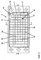
- FIG. 1 shows a preferred embodiment of a falling-film evaporator (1) to be used according to the invention. which is particularly suitable for concentrating solutions containing a thermolabile component.
- a container comprising a container side wall (12), a container bottom (13) and a container lid (14), in this preferred embodiment, two stacks (2, 2 ') of evaporator modules (3, 3') according to the invention are located directly above one another, with intermediate ones slit-shaped spaces, which are not visible in Figure 1, however, fixed by means of any, not shown in Figure 1 holding device.
- the container has in the upper part of a nozzle for withdrawing the gas phase (gas, steam or mist) (10) and in the lower part of a nozzle for withdrawing a liquid phase (11).
- the stack-shaped vertically arranged plate-shaped modules of the two stacks are arranged directly above one another so that the orientation of the evaporator compartments of the upper stack substantially corresponds to that of the lower stack.
- the spaces between the modules are not visible in Figure 1, since the narrow sides are closed in this embodiment.
- the term "substantially over the entire width" means that the gap can be interrupted by structurally related welds, spacers and the like.
- the gap-shaped spaces in both stacks are open both above and below substantially over the entire width of the modules, so that in the invention. Process formed gaseous phase can escape quickly and without a complicated pipe system down or up.
- a device (9) for introducing a gas into the gap-shaped evaporation chambers is arranged between the two stacks.
- a gas-tight separating element (16) is arranged between the container wall and the upper edge of the upper stack.
- This separator can be designed in any way, provided that it is ensured that backmixing is avoided.
- the container lid is placed directly on the outer edge of the upper stack and the container bottom directly on the outer edge of the lower stack and the outer sides of the plate stack represent the container wall.
- the plate stacks comprise a multiplicity of evaporator modules (3) and evaporator chambers arranged between them.
- the gap width (s) between two evaporator modules and the dimensional stability of the evaporator chambers is effected by spacers (22) (see FIGS. 2 to 5).
- end modules which can be designed as simple plates, are located on both sides of the plate stack.
- the plate stack is fixed by means of any tensioning device, in Figure 1 comprises these threaded bolts and nuts (5).
- one line for the heating medium inlet (6), the heating medium return line (7) and the inlet of a cooling medium (8) for the lower stack can be seen in FIG.
- the module comprises the two on each other lying plates (29) and (30) with interposed channels (20) for a heat transfer medium.
- the stability of the plates is fixed by welding points (24) and / or welds.
- On the outer sides of the plates are a plurality of spacers (22); Gaps (23) between the spacers allow cross-mixing of the gaseous phase on both sides of the spacers, conveniently arranged in a vertical line.
- the outer surfaces (27) of the plates (29, 30) are each provided with a family of parallel microchannels, these microchannels generally extending over the entire plate height.
- This line and the uppermost part of the plates is covered by means of a cover plate (21) such that the liquid is introduced directly from the line (26) only in the microchannels.
- FIG. 4 again illustrates the basic construction of an evaporator module comprising two plates (29, 30) with the cavities for the heat transfer medium (20), the spacers (22), a distributor line (19) for the liquid medium and bores (18). for threaded bolt for fixing the module package.
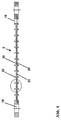
- FIG. 2 shows a plan view of an evaporator plate (3).
- the sets (not shown) of parallel microchannels In the fields between the spacers (27) are the sets (not shown) of parallel microchannels.
- the flow direction of Liquid in the microchannels is indicated by the arrow (28).
- the Schumediumzulauf (6), the Schumedium Weglauf (7) and some channels (20) for the heat transfer within the plate are also shown in dashed lines.
- the feeding device for the liquid medium comprises the distribution line (19), the supply line (26) and the cover plate (21). Also indicated are welding points (24) and bores (18) for the threaded bolts.
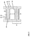
- FIG. 5 shows a detail of two adjacent evaporator modules (3).
- the gap width (s) of the evaporator space formed between two evaporator modules is determined by the height of the spacers (22).
- flocks (31) of parallel microchannels (32), between which the webs (32, 33) are located can be seen. Shown are also the depth (t) of the Mirkokanäle and the width (b) of the same.
- the gap width (s) measured from the bottom of the microchannels, is greater than the depth (t) thereof and less than 20 mm.
- s is greater than 2 t, in particular greater than 5 t and particularly preferably greater than 100 microns.
- the width b of the microchannels can be within wide limits, but it is expedient to have a width of less than 2000 ⁇ m, in particular such in the range from 50 to 500 ⁇ m.
- the depth (t) of the microchannels is generally less than 1000 microns, in particular, it is in the range of 25 to 500 microns.
- the width of the webs between the microchannels is less critical, but determines the enforceable amount of liquid, so it is advantageous if the web width is less than 1000 microns, in particular in the range of 25 to 500 microns.
- Another object of the invention is directed to the device suitable for carrying out the method according to the device claims.
- the Verdampferräüme are closed at their narrow sides and open at the top and bottom substantially over the entire width of the modules.
- the preferred embodiment of a falling-film evaporator according to the invention according to FIG. 1 can also be modified such that a single module package is used instead of the combination of two stacks of modules with intermediate gap-shaped spaces shown in FIG. 1, but the cavities for the heat transfer medium extending in the evaporator modules be arranged so that several horizontally arranged zones result. Each zone is assigned a separate heating medium inlet and outlet so that a gradual temperature profile can be set via the evaporator modules.
- a falling-film evaporator with a plurality of stacks of evaporator modules with associated gap-shaped spaces between them, these stacks are located laterally offset one above the other in one or more containers.
- This embodiment is advantageous when in the lower stack of a liquid medium, a gaseous phase recovered and these in the upper stack with supply of a second reaction component, which may be gaseous, is reacted and the reaction product itself is liquid and thus at the lower end of the upper Piles dripping off and not combined with the liquid dripping from the lower stack.
- the modules may be completely or partially coated with an effective catalyst.
- modules with a family of parallel microchannels in a second module package are not required in all cases, it is still advantageous to also equip the modules of the second stack with families of parallel microchannels if the second component itself is a liquid and / or a liquid Catalyst should be present in direct layer.
- the process according to the invention may be a simple evaporation or formation of a gaseous phase by decomposition, or a combination of the formation of the gas phase with immediately subsequent reaction with a second reaction component.
- This reaction can be any reaction, for example oxidation, epoxidation, hydrogenation or addition reaction.
- the second reactant may be gaseous or liquid.
- An example of the use of the device according to the invention is directed to the evaporation of an aqueous hydrogen peroxide solution to obtain (i) a concentrated aqueous hydrogen peroxide solution and (ii) a vapor phase containing hydrogen peroxide and water, which in turn immediately follow-up reactions such as the epoxidation of an olefin such as propylene. can be supplied in the gas phase.
- Another example of the use of the method according to the invention relates to the provision of a gas stream obtained from a liquid, for example one Ammonia gas stream from liquid ammonia, which is easily and quickly regulated and can be supplied as needed to a chemical reaction.
- the need-based provision under substantially constant pressure can be in contrast to conventional methods, which often lead to a pressure drop and also have the risk of bubbling, by controlling the heat supply to the evaporator modules and / or control of the liquid supply, such as a liquid supply to a reduced or increased number of modules effect.
Abstract
Description
Die Erfindung richtet sich auf ein Verfahren zur Gewinnung einer gasförmigen Phase aus einem flüssigen Medium durch mindestens teilweises Verdampfen des flüssigen Mediums oder mindestens einer darin enthaltenen Komponente öder Freisetzen einer durch Spaltung gebildeten Komponente. Das Verfahren wird in einem modular aufgebauten Fallfilmverdampfer, der stapelförmig vertikal oder geneigt angeordnete plattenförmige Module und spaltförmige Verdampferräume zwischen jeweils zwei Modulen umfasst, durchgeführt.The invention is directed to a process for recovering a gaseous phase from a liquid medium by at least partially vaporizing the liquid medium or at least one component contained therein or releasing a component formed by cleavage. The method is carried out in a modularly constructed falling-film evaporator which comprises stack-shaped vertically or inclined plate-shaped modules and gap-shaped evaporator spaces between in each case two modules.
Bei der erfindungsgemäß zu verwendenden Vorrichtung handelt es sich um einen Reaktor, welcher im technischen Maßstab, insbesondere im tons-Maßstab, betrieben werden kann.The device to be used according to the invention is a reactor which can be operated on an industrial scale, in particular on a tons scale.
Fallfilmverdampfer, welche als horizontale oder vertikale Rohrbündel oder auch als vertikale Plattenstapel ausgeführt sein können, werden in der chemischen Industrie in vielseitiger Weise eingesetzt. Der Vorteil von Fallfilmverdampfern gegenüber üblichen Zwangsumlauf- oder Naturumlaufverdampfern ist die geringe Überhitzung der Flüssigkeit. Während bei den Fallfilmverdampfern der Flüssigkeitsfilm ausschließlich durch die Schwerkraft über eine Oberfläche fließt - beispielhaft wird auf das US-Patent 5,203,406 verwiesen - werden bei besonders thermolabilen Substanzen Dünnschichtverdampfer eingesetzt, bei welchen mittels mechanischer Mittel auf einer Verdampferoberfläche ein dünner Film erzeugt, und durch Turbulenzen im Film der Stoff- und Wärmeübergang verbessert werden - beispielhaft wird auf das US-Patent 6,173,762 verwiesen. Beispiele für Anwendungen von Fallfilmverdampfern sind: Entfernen organischer Lösungsmittel aus Lösungen, um darin gelöste thermolabile Produkte anzureichern und das Lösemittel zurückzugewinnen; Aufkonzentrieren von Fruchtsäften (Lebensmittelchemie); Gewinnung von Süsswasser aus Salz- oder Brackwasser.Falling film evaporators, which may be implemented as horizontal or vertical tube bundles or else as vertical plate stacks, are used in many ways in the chemical industry. The advantage of falling film evaporators over conventional forced circulation or natural circulation evaporators is the low overheating of the liquid. While in the falling film evaporators, the liquid film flows solely by gravity over a surface - for example, refer to the US Patent 5,203,406 - are used in particularly thermolabile substances thin-film evaporator in which by means of mechanical means on an evaporator surface produces a thin film, and by turbulence in Film of the material and heat transfer can be improved - by way of example, reference is made to US Pat. No. 6,173,762. Examples of applications of Falling film evaporators are: removing organic solvents from solutions to enrich for dissolved thermolabile products and to recover the solvent; Concentration of fruit juices (food chemistry); Production of fresh water from salt or brackish water.
Der Fallfilmverdampfer gemäß US-Patent 5,203,406 umfasst ein Paket von im wesentlichen vertikal in einem bestimmten Abstand voneinander angeordneten Wärmeaustauscherplatten, wobei jeder zweite Zwischenraum zwischen den Platten als Verdampferraum ausgebildet ist. Hinweise, wonach die Verdampferplatten strukturiert sind, lassen sich diesem Dokument nicht entnehmen.The falling-film evaporator according to US Pat. No. 5,203,406 comprises a package of heat exchanger plates arranged substantially vertically at a certain distance from one another, wherein every second space between the plates is designed as an evaporator space. Instructions, according to which the evaporator plates are structured, can not be found in this document.
Aus dem US-Patent 6,173,762 B1 ist bekannt, zur Verbesserung des Wärme- und Stoffübergangs die filmtragende Oberfläche eines Wärmeaustauscherrohres für einen Fallfilmverdampfer mit Rippen und Rillen zu strukturieren. Die Höhe der Rippen wird mit 0,2 bis 0,8 mm angegeben, die Anzahl Rippen mit 900 bis 1100/m.From US Pat. No. 6,173,762 B1 it is known to structure the film-carrying surface of a heat exchanger tube for a falling-film evaporator with ribs and grooves in order to improve the heat and mass transfer. The height of the ribs is specified as 0.2 to 0.8 mm, the number of ribs as 900 to 1100 / m.
In üblichen Fallfilmverdampfern dürfen minimale Werte der Berieselüngsdichte und der Filmdicke, um 1 mm bei Fallfilmverdampfern und 0,5 mm bei Dünnschichtverdampfern nicht unterschritten werden, weil es sonst zu Filmabrissen, zum Trockenlaufen und zu unerwünschten "hot-spots" und damit bei der Konzentrierung eines flüssigen Mediums, welches eine thermolabile Komponente enthält, zu unerwünschten Zersetzungserscheinungen kommen kann.In conventional falling-film evaporators, minimum values of spray density and film thickness, by 1 mm for falling-film evaporators and 0.5 mm for thin-film evaporators, must not be fallen short because otherwise film breaks, dry running and undesired "hot spots" and thus concentration of a film liquid medium containing a thermolabile component may cause undesirable decomposition phenomena.
Einen modular aufgebauten Mikroreaktor zur Durchführung von Reaktionen zwischen einem flüssigen und einem gasförmigen Reaktionspartner lehrt die DE 100 36 602 A1. Dieser Mikroreaktor umfasst einen Stapel aus einer beliebigen Anzahl von vertikal oder geneigt angeordneten Fluidführungsplatten, einer gleichen Anzahl Zwischenplatten und zwischen je zwei Platten spaltförmigen Reaktionsräumen. Die Fluidführungsplatten weisen parallel angeordnete Mikrokanäle auf, in welchen eine Flüssigkeit durch Schwerkraft und/oder Kapillarkräfte in ununterbrochenen Kapillarfäden fließen und mit einem Gas in Kontakt treten und reagieren kann. Die Fluidführungsplatte kann mit einem Katalysator beschichtet sein und an ihrer Rückwand mit einem Wärmetauschermedium in Kontakt stehen. Das entstehende flüssige Reaktionsgemisch wird am unteren Ende der Fluidführungsplatten über Sammelkanäle abgeleitet. Nachteilig an dem Mikroreaktor gemäß DE 100 36 602 A1 ist der durch viele Zu- und Ableitungen, Sammel- und Verteilerkanäle, Druckverlustbarrieren und spezielle Rampen bedingte sehr komplizierte technische Aufbau. Durch den modularen Aufbau kann zwar die Durchsatzmenge in gewissem Umfang gesteigert werden, jedoch lassen sich diesem Dokument keine Anregungen entnehmen, wie das miniaturisierte Reaktionssystem verändert werden muss, um es im technischen Maßstab und insbesondere für großtechnische Einsatzzwecke in wirtschaftlicher Weise einsatzfähig zu machen. Anregungen, den Mikroreaktor als Verdampfer zu verwenden, lassen sich dem Dokument nicht entnehmen.A modular microreactor for carrying out reactions between a liquid and a gaseous reactant is taught by DE 100 36 602 A1. This Microreactor comprises a stack of any number of vertically or inclined fluid guide plates, an equal number of intermediate plates and between two plates gap-shaped reaction spaces. The fluid guide plates have parallel microchannels in which a liquid can flow by gravity and / or capillary forces in uninterrupted capillary threads and contact and react with a gas. The fluid guide plate may be coated with a catalyst and in contact with a heat exchange medium at its rear wall. The resulting liquid reaction mixture is discharged at the lower end of the fluid guide plates via collecting channels. A disadvantage of the microreactor according to DE 100 36 602 A1 is the very complicated technical structure caused by many inlets and outlets, collection and distribution channels, pressure loss barriers and special ramps. Although the throughput can be increased to some extent due to the modular structure, this document can be no suggestions as to how the miniaturized reaction system must be changed in order to make it economically feasible on an industrial scale and especially for large-scale applications. Suggestions for using the microreactor as an evaporator can not be found in the document.
Aus der WO 02/18042 A1 ist ein weiterer Reaktor zum Durchführen von Reaktionen zwischen mindestens zwei fluiden Reaktanden im technischen Maßstab bekannt. Der Reaktor umfasst einen Stapel aus im wesentlichen quaderförmigen, vertikal angeordneten Wandelementen mit integrierter Kühlvorrichtung und spaltförmigen Reaktionsräumen zwischen den Wandelementen. Die Wandelemente können zwar strukturiert und mit einem Katalysator belegt sein, jedoch finden sich in diesem Dokument keine Hinweise, wonach die Struktur aus einer Schar paralleler Mikrokanäle bestehen und der Reaktor als Verdampfer verwendet werden könnte.From WO 02/18042 A1 a further reactor for carrying out reactions between at least two fluid reactants on an industrial scale is known. The reactor comprises a stack of substantially cuboid, vertically arranged wall elements with integrated cooling device and gap-shaped reaction spaces between the wall elements. Although the wall elements can be structured and covered with a catalyst, however There is no evidence in this document that the structure consists of a family of parallel microchannels and that the reactor could be used as an evaporator.
Die DD-Patentschrift 246 257 lehrt eine verfahrenstechnische Mikroapparatur, die aus einem Stapel aus einzelnen Substratplättchen mit eingearbeiteten Vertiefungen besteht, wobei die Substratplättchen zur Bildung geschlossener kanalförmiger Hohlräume abgedeckt sind. Dieser Mikroreaktor enthält kanalförmige Reaktionsräume, in welchen außer einer chemischen Reaktion auch Verdampfungsprozesse durchgeführt werden können. Ein derartiger Mikroreaktor eignet sich als Reaktionsgefäß zur Anwendung in der chemischen mikroanalytik, jedoch nicht zur Verwendung als Verdampfer im Rahmen eines Prozesses in technischem (tons) Maßstab.DD Patent 246,257 teaches a process micro-apparatus consisting of a stack of individual substrate chips with indented recesses, the substrate platelets being covered to form closed channel-shaped cavities. This microreactor contains channel-shaped reaction chambers in which, in addition to a chemical reaction, evaporation processes can also be carried out. Such a microreactor is suitable as a reaction vessel for use in chemical microanalytics, but not for use as an evaporator in a process on an industrial (tons) scale.
Aus der DE-Offenlegungsschrift 1 667 241 ist ein Reaktor für chemische Reaktionen bekannt, welcher einen Stapel aus plattenförmigen, gegebenenfalls mit einem Katalysator beschichteten Modulen und zwischen diesen angeordneten spaltförmigen Reaktionsräumen, Abstandshaltevorrichtungen zur Begrenzung der Reaktionsräume und Einlass- und Auslassvorrichtungen in diese Räume umfasst. Der Flächenabstand zwischen den Platten liegt im Bereich von 0,001 und 6,3 mm, so dass der wirksame Reaktionsraum gegenüber Mikroreaktoren vergrößert sein kann. Die Oberfläche der Platten auf welchen ein Flüssigkeitsfilm zweckmäßigerweise unter Zentrifugalkraft fließt, kann zwar geätzt sein, Hinweise auf die Anwesenheit parallel angeordneter Mikrokanäle lassen sich dem Dokument jedoch nicht entnehmen. Der Plattenstapel kann zwar insgesamt temperiert werden, Vorrichtungen zum Temperieren einzelner Platten sind jedoch nicht vorgesehen, so dass sich diese Vorrichtung nicht unmittelbar zur Verwendung in einem großtechnischen Prozess eignet.
Der Reaktor gemäß US-Patent 5,811,062 umfasst mehrere vertikal übereinander angeordnete Laminate mit darin angeordneten Mirkostrukturelementen, wie insbesondere Mikrokanälen. Durch zusammenschaltung vieler derartiger Mikroreaktoren lassen sich auch Reaktionen im Makromaßstab durchführen. Die Abmessungen der Mikrokomponenten liegen im Bereich von etwa 1 µm bis 1 cm. Die Breite der Rinnen in den Laminaten, woraus durch Abdeckung die Kanäle gebildet werden, wird mit 1 µm bis 1 mm angegeben; sofern oberhalb der Rinnen überhaupt ein Spalt verbleibt, soll die Spaltweite weniger als 100 µm, insbesondere weniger als 10 µm betragen. Zwar kann der Reaktor auch als Verdampfer verwendet werden, jedoch findet sich in diesem Dokument keine Anregung die Laminate mit den Mikrostrukturen, also den Reaktionskanälen in anderer Weise als vertikal anzuordnen. Der Reaktor wird nicht als Fallfilmverdampfer verwendet. Nachteilig an diesem Reaktor ist ferner, dass durch die Dimensionierung der Rinnen, selbst wenn sich über diesen noch einen geringer Spalt befindet, einer Verdampfung der in Rinnen fließenden Flüssigkeit enge Grenzen setzt.The reactor according to US Pat. No. 5,811,062 comprises a plurality of vertically stacked laminates with microstructure elements arranged therein, in particular microchannels. By interconnecting many such microreactors, it is also possible to carry out reactions on a macro scale. The dimensions of the microcomponents are in the range of about 1 .mu.m to 1 cm. The width of the grooves in the laminates, from which the channels are formed by covering, is given as 1 μm to 1 mm; if a gap remains at all above the grooves, the gap width should be less than 100 μm, in particular less than 10 μm. Although the reactor can also be used as an evaporator, there is no suggestion in this document of arranging the laminates with the microstructures, that is to say the reaction channels, in a manner other than vertical. The reactor is not used as a falling film evaporator. A disadvantage of this reactor is further that by dimensioning the grooves, even if there is still a small gap over this, evaporation of the liquid flowing in grooves sets narrow limits.
Das EP-Patent 0 688 242 lehrt eine integrale Struktur für die chemische Verarbeitung und Produktion, die eine Vielzahl von miteinander verbundenen Plättchen mindestens einen dreidimensional gewundenen durchgehenden Kanal zwischen benachbarten Plättchen sowie mindestens eine Einlass- und eine Auslassöffnung für die umzusendenden Stoffe umfasst. Dieser modular aufgebaute Mikroreaktor kann ferner zwischen benachbarten Plättchen Kanäle zum Durchleiten eines Wärmeträgermediums aufweisen. Auch dieser Mikroreaktor lässt sich nicht durch Parallelschaltung vieler Reaktoren und/oder Vergrößerung der Plattenzahl innerhalb eines Stapels beliebig vergrößern, um ein Verfahren in großtechnischem Maßstab durchführen zu können. Anregungen diesen Mikroreaktor so umzugestalten, dass er als Fallfilmreaktor Anwendung finden kann, sind diesem Dokument nicht zu entnehmen.EP patent 0 688 242 teaches an integral structure for chemical processing and production comprising a plurality of interconnected platelets, at least one three-dimensional coiled through channel between adjacent platelets, and at least one inlet and outlet port for the substances to be transposed. This modular microreactor can also have channels between adjacent plates for passing a heat transfer medium. This too Microreactor can not be arbitrarily increased by parallel connection of many reactors and / or increase the number of plates within a stack in order to carry out a process on a large scale. Suggestions for reshaping this microreactor so that it can be used as a falling-film reactor can not be found in this document.
Aufgabe der vorliegenden Erfindung ist es demgemäß, ein verbessertes Verfahren zur Gewinnung einer gasförmigen Phase aus einem flüssigen Medium unter Verwendung eines modular aufgebauten Fallfilmverdampfers, welcher stapelförmig vertikal oder geneigt angeordnete plattenförmige Module und spaltförmige Verdampferräume zwischen den Modulen enthält, aufzuzeigen, wobei ein wesentlicher Aspekt der Verbesserung darin liegt, dass das Verfahren im technischen Maßstab (= tons-maßgtab) in einfacher und wirtschaftlicher Weise durchgeführt werden kann.Accordingly, it is an object of the present invention to provide an improved process for recovering a gaseous phase from a liquid medium using a modular falling film evaporator containing stacked vertically or slanted plate-shaped modules and gap-shaped evaporator spaces between the modules The improvement lies in the fact that the process on an industrial scale (= tons-Maßgtab) can be carried out in a simple and economical manner.
Eine weitere Aufgabe der Erfindung richtet sich darauf, ein flüssiges Medium, welches eine thermolabile Komponente enthält, ohne nennenswerte Zersetzung und insbesondere ohne das Risiko einer unkontrollierten Zersetzung zu konzentrieren, wobei die gebildete gasförmige Phase und die flüssige konzentrierte Phase weiteren Verwendungen zugeführt werden können.Another object of the invention is to concentrate a liquid medium containing a thermolabile component without appreciable decomposition and in particular without the risk of uncontrolled decomposition, whereby the formed gaseous phase and the liquid concentrated phase can be put to further uses.
Eine weitere Aufgabe richtet darauf, ein durch Verdampfen einer Flüssigkeit gewonnenes Gas unter konstantem Druck und schnell regelbar für eine Folgereaktion mit einer zweiten Reaktionskomponente zur Verfügung zu stellen.A further object is to provide a gas obtained by evaporation of a liquid under constant pressure and quickly controllable for a subsequent reaction with a second reaction component.
Eine weitere Aufgabe der Erfindung richtet sich auf die Bereitstellung einer Vorrichtung zur Durchführung des erfindungsgemäßen Verfahrens im technischem Maßstab.A further object of the invention is directed to the provision of a device for carrying out the method according to the invention on an industrial scale.
Gemäß einer weiteren Aufgabe soll die Vorrichtung einen möglichst einfachen Aufbau aufweisen und zudem leicht an unterschiedliche Kapazitätsanförderungen angepasst werden können.According to a further object, the device should have the simplest possible structure and, moreover, it can easily be adapted to different capacity deliveries.
Gemäß einer weiteren Aufgabe sollte die erfindungsgemäße Vorrichtung selbst als Reaktor für eine weitere Umsetzung der gebildeten Gasphase und/oder der sich konzentrierenden flüssigen Phase mit einer oder mehreren weiteren Reaktionskomponenten eigenen.According to a further object, the device according to the invention should itself be suitable as a reactor for further reaction of the gas phase formed and / or the concentrating liquid phase with one or more further reaction components.
Die vorgenannten Aufgaben und weitere Aufgaben, wie sie aus der nachfolgenden Beschreibung leicht herleitbar sind, werden durch die Verwendung eines Fallfilmverdampfers, welcher auf den Verdampfermodulen eine Schar paralleler Mikrokanäle in einer für einen Fallfilm geeigneten Orientierung aufweist und dessen Verdampferräume spaltförmig und oben und/oder unten geöffnet sind, gelöst.The foregoing objects and other objects, as readily derivable from the following description, are achieved by the use of a falling film evaporator which has a family of parallel microchannels on the evaporator modules in a direction suitable for a falling film and its evaporator spaces in a gap shape and at the top and / or bottom are opened, solved.
Gefunden wurde demgemäß ein Verfahren zur Gewinnung einer gasförmigen Phase aus einem flüssigen Medium im technischen Maßstab, durch mindestens teilweises Verdampfen des flüssigen Mediums oder mindestens einer darin enthaltenen Komponente oder Freisetzen einer aus dem flüssigen Medium durch Spaltung gebildeten Komponente in einem modular aufgebauten Fallfilmverdampfer, umfassend, stapelförmig vertikal oder geneigt angeordnete plattenförmige Module, wobei mindestens jeder zweite Modul als Verdampfermodul ausgebildet ist, und spaltförmige Verdampferräume zwischen einander zugekehrten Seitenflächen Von im wesentlichen gleich großen, rechteckigen Modulen,
dadurch gekennzeichnet,
dass man einen Fallfilmverdampfer verwendet, dessen Verdampfermodule zumindest auf einer den spaltförmigen Verdampferräumen zugekehrten Seite eine Schar paralleler Mikrokanäle aufweisen, deren Orientierung der Laufrichtung des darin durch Schwerkraft und/oder Kapillarkräfte fließenden flüssigen Mediums entspricht, und dessen Verdampferräume oben und/oder unten über im wesentlichen die gesamte Breite der Module offen sind, das flüssige Medium mittels einer Aufgabevorrichtung den Mikrokanälen zuführt, die Mikrokanäle mittels eines die Verdampfermodule durchströmenden Wärmeträgermediums indirekt beheizt und die entstehende gasförmige Phase aus den oben und/oder unten offenen verdampferräumen abzieht.Accordingly, a process has been found for obtaining a gaseous phase from a liquid medium on an industrial scale, by at least partially vaporizing the liquid medium or at least one component contained therein or releasing a component formed by cleavage from the liquid medium in a modularly constructed falling film evaporator comprising stacked vertically or inclined arranged plate-shaped modules, wherein at least every second module is designed as an evaporator module, and gap-shaped evaporator spaces between mutually facing side surfaces of substantially equal-sized, rectangular modules,
characterized,
to use a falling-film evaporator whose evaporator modules, at least on a side facing the gap-shaped evaporation spaces, have a family of parallel microchannels whose orientation corresponds to the running direction of the liquid medium flowing therein by gravity and / or capillary forces and whose evaporation spaces above and / or below substantially the entire width of the modules are open, the liquid medium by means of a feeder feeds the microchannels, indirectly heats the microchannels by means of a heat transfer medium flowing through the evaporator modules and subtracts the resulting gaseous phase from the top and / or bottom open evaporator chambers.
Die Unteransprüche richten sich auf bevorzugte Ausführungsformen des Verfahrens.The subclaims are directed to preferred embodiments of the method.
Bei dem flüssigen Medium, welches der jeweiligen Schar paralleler Mikrokanäle zugeführt wird, kann es sich um einen reinen Stoff oder um ein Stoffgemisch, beispielsweise eine Lösung einer oder mehrerer Komponenten in einem Lösungsmittel, handeln. Der Begriff "flüssige Medium" schließt Schmelzen ein. Unter den Verfahrensbedingungen, welche sich bezüglich Temperatur und Druck im wesentlichen nach den Stoffeigenschaften des flüssigen Mediums richten, wird durch mindestens teilweises Verdampfen einer Komponente des flüssigen Mediums oder durch gezielte thermische Spaltung einer darin enthaltenen Komponente eine gasförmige Phase gebildet. Der Begriff "gasförmige Phase" umfasst auch Dämpfe und Nebel.The liquid medium which is supplied to the respective family of parallel microchannels may be a pure substance or a substance mixture, for example a solution of one or more components in a solvent. The term "liquid medium" includes melts. Under the process conditions, which are essentially based on the material properties of the liquid medium in terms of temperature and pressure, by at least partial evaporation of a component of the liquid medium or by targeted thermal decomposition of a component contained therein formed gaseous phase. The term "gaseous phase" also includes vapors and mists.
Überraschender Weise lässt sich ein erfindungsgemäßer Reaktor, der analog dem Mikroreaktor gemäß DE 100 36 602 A1 eine Fluidführungsplatte und spaltförmige Reäktionsräume enthält, die Spalten jedoch oben und/oder unten über im wesentlichen die gesamte Breite der Platten offen sind, zur Verdampfung eines flüssigen Mediums verwenden. Das genannte Dokument gibt diesbezüglich keinerlei Anregung. Durch die nachfolgend weiter erörterten Besonderheiten des erfindungsgemäß zu verwendenden Fallfilmverdampfers lässt sich das Verfahren im technischen Maßstab realisieren.Surprisingly, a reactor according to the invention which, analogously to the microreactor according to DE 100 36 602 A1, contains a fluid guide plate and gap-shaped reaction chambers, but the gaps are open at the top and / or bottom over substantially the entire width of the plates, can be used for the evaporation of a liquid medium , The said document does not provide any suggestions in this respect. By further discussed below peculiarities of the falling film evaporator to be used according to the invention, the method can be realized on an industrial scale.
Die Begriffe Fallfilmverdampfer, Verdampfermodule und Verdampferräume werden in der vorliegenden Erfindung verwendet, obgleich es sich nicht in allen Fällen um eine Verdampfung des flüssigen Mediums oder einer darin enthaltenen Komponente handelt, sondern auch um die Freisetzung einer durch gezielte Spaltung gebildeten Komponente handeln kann. Zudem wird der Begriff Fallfilmverdampfer verwendet, obgleich es sich bei dem über die Verdampfermödule fließenden Flüssigkeit nicht um einen flächigen Film, sondern um parallel nebeneinander fließende ununterbrochene Kapillarfäden handelt. Durch die Strukturierung der Verdampferoberfläche mit einer Schar offener paralleler Mikrokanäle ist es möglich, die Berieselungsdichte und Dicke der Kapillarfäden gegenüber den Werten eines Films in konventionellen Fallfilmverdampfern abzusenken und dadurch die Stoff- und Wärmeübergangskoeffizienten signifikant zu erhöhen, ohne dass es zum Abreißen der Kapillarfäden, zum Trockenlaufen derselben oder zu unerwünschten Hot-Spots kommt.The terms falling film evaporators, evaporator modules, and evaporator compartments are used in the present invention, although not all of them involve evaporation of the liquid medium or a component contained therein, but may also involve the release of a component formed by targeted cleavage. In addition, the term falling-film evaporator is used, although the liquid flowing through the evaporator module is not a flat film, but continuous capillary threads flowing parallel to one another. By structuring the evaporator surface with a family of open parallel microchannels, it is possible to lower the irrigation density and thickness of the capillary filaments compared to the values of a film in conventional falling film evaporators and thereby significantly increase the mass and heat transfer coefficients without causing capillary filaments to break off Dry running of the same or to undesirable hot spots occurs.
Bei dem erfindungsgemäß zu verwendenden Fallfilmverdampfer handelt es sich um einen modular aufgebauten Fallfilmverdampfer, der plattenförmige Verdampfermodule enthält und somit leicht und mit geringem technischen Aufwand an eine gewünschte Verdampferkapazität angepasst werden kann. Im Prinzip lässt sich das erfindungsgemäße Verfahren auch in einem Fallfilmverdampfer durchführen, der als Module mehrere konzentrisch ineinander gestellte Rohre umfasst, wobei mindestens ein Teil der Ringspalte zwischen den Rohren als Verdampferräume ausgebildet sind und mindestens eine Rohrwandung dieser Verdampferräume eine Schar paralleler Mikrokanäle aufweist. Ein derartiger modular aufgebauter rohrförmiger Fallfilmverdampfer ist jedoch technisch aufwendiger als ein plattenförmiger Verdampfer und zudem lässt er sich nicht in ebenso einfacher Weise vergrößern, wie der dem erfindungsgemäß zu verwendende modular aufgebaute Fallfilmverdampfer mit stapelförmig angeordneten plattenförmigen Modulen.The falling-film evaporator to be used according to the invention is a modularly constructed falling-film evaporator which contains plate-shaped evaporator modules and can therefore be adapted easily and with little technical effort to a desired evaporator capacity. In principle, the method according to the invention can also be carried out in a falling-film evaporator which comprises a plurality of concentrically interconnected tubes as modules, wherein at least part of the annular gaps between the tubes are designed as evaporator chambers and at least one tube wall of these evaporator chambers has a family of parallel microchannels. However, such a modular tubular falling film evaporator is technically more complicated than a plate-shaped evaporator and, moreover, it can not be enlarged in an equally simple manner as that of the modularly constructed falling-film evaporator to be used according to the invention with plate-shaped modules arranged in a stack.
Die im erfindungsgemäßen Verfahren gebildete gasförmige Phase kann aus den Verdampferräumen abgezogen und außerhalb derselben einer weiteren Verwendung zugeführt werden. Alternativ hierzu kann die gewonnene gasförmige Phase unmittelbar in den Verdampferräumen mit einer diesen zugeführten zweiten gasförmigen Reaktionskomponente in Gegenwart oder in Anwesenheit eines Katalysators auf mindestens einem Teil der die Verdampferräume begrenzenden Flächen weiter umgesetzt werden. Der zweite gasförmige Reaktionspartner kann hierbei im Gleich- oder im Gegenstrom zur Laufrichtung des flüssigen Mediums in die Verdampferräume eingeleitet werden. Sofern die Umsetzung des in-situ gebildeten Gases mit dem eingeleiteten zweiten Reaktionspartner heterogen katalysiert wird, ist es vorteilhaft, wenn die den Verdampferseiten gegenüberliegenden Seiten der Verdampferräume mit einem wirksamen Katalysator beschichtet sind.The gaseous phase formed in the process according to the invention can be withdrawn from the evaporator chambers and fed to a further use outside thereof. Alternatively, the recovered gaseous phase can be further reacted directly in the evaporator chambers with a second gaseous reaction component supplied thereto in the presence or in the presence of a catalyst on at least part of the surfaces bounding the evaporator spaces. The second gaseous reactant can be introduced in the same or in countercurrent to the direction of the liquid medium in the evaporator chambers. If the reaction of the gas formed in situ with the introduced second reactant is catalysed heterogeneously, it is advantageous if the the evaporator sides opposite sides of the evaporator chambers are coated with an effective catalyst.
Gemäß einer weiteren Ausführungsform wird die in den Verdämpferräumen gebildete gasförmige Phase mittels eines von unten oder oben in die Verdampferräume eingeleiteten inerten oder reaktiven Gases als solches oder teilweise umgesetztes Gas aus den Verdampferräumen ausgetragen. Sofern in den Verelampferräumen bereits eine chemische Reaktion durchgeführt wird, handelt es sich bei den Verdampferräumen gleichzeitig auch um Reaktiärisräume.According to a further embodiment, the gaseous phase formed in the Verdampferräumen is discharged by means of an introduced from below or above in the evaporator chambers inert or reactive gas as such or partially reacted gas from the evaporator chambers. If a chemical reaction is already carried out in the Verelampfer rooms, the evaporator rooms are at the same time also Reaktiärisräume.
Das Gemisch aus der gewonnenen Gasphase mit dem Inertgas oder einem Reaktiönsgas kann zum Beispiel in einem nachgeschalteten Reaktor, insbesondere einem modularen plattenförmigen Reaktor umgesetzt werden.The mixture of the recovered gas phase with the inert gas or a Reaktiönsgas can be implemented for example in a downstream reactor, in particular a modular plate-shaped reactor.
Das Volumen des in die Mikrokanäle eingespeisten flüssigen Mediums nimmt während des Durchfließens der Mikrokanäle im allgemeinen ab. Lediglich wenn das sich konzentrierende flüssige Medium mit einem in die Verdampferräume geleiteten weiteren gasförmigen Reaktionspartner weiter umgesetzt wird, kann das Volumen im wesentlichen konstant bleiben, oder größer werden. Das aus den Mikrokanälen abfließende flüssige Medium wird entweder unmittelbar in einem unter den Verdampferräumen angeordneten Behälter gesammelt oder mittels einer Ablaufrinne aus dem Fallfilmverdampfer abgezogen.The volume of the liquid medium fed into the microchannels generally decreases as the microchannels flow through. Only when the concentrating liquid medium is further reacted with a further gaseous reactant conducted into the evaporator spaces, the volume can remain substantially constant, or become larger. The effluent from the microchannels liquid medium is either collected directly in a container arranged under the evaporator chambers or withdrawn from the falling film evaporator by means of a gutter.
Das erfindungsgemäße Verfahren eignet sich in besonderer Weise zur Konzentrierung eines solchen flüssigen Mediums, das eine oder mehrere thermolabile Verbindungen enthält. Die eine oder mehreren thermolabilen Stoffe können sowohl in der sich konzentrierenden flüssigen Phase oder/und in der durch Verdampfen gebildeten Gas- bzw. Dampfphase enthalten sein. Zum Zwecke der Konzentrierung eines derartigen Mediums kann es besonders vorteilhaft sein, wenn der zu verwendende Fallfilmverdampfer mehrere Stapel aus vertikal angeordneten Modulen und dazwischen liegenden spaltförmigen Verdampferräumen mit mindestens einer Schar paralleler Mikrokanäle in jedem Verdampferraum umfasst. Zweckmäßigerweise sind die Stapel übereinander angeordnet und die spaltförmigen Räume zwischen den Modulen über im wesentlichen die gesamt Breite der Module oben und unten offen, so dass diese im wesentlichen frei und ohne nennenswerten Druckverlust von einem Gas durchströmt werden können und zusätzlich die aus einem oberen Stapel aus den Mikrokanälen ablaufende Flüssigkeit den Mikrokanälen des darunter liegenden Stapels zugeführt werden kann.The method according to the invention is particularly suitable for concentrating such a liquid medium, containing one or more thermolabile compounds. The one or more thermolabile substances can be contained both in the concentrating liquid phase and / or in the vapor or vapor phase formed by evaporation. For the purpose of concentrating such a medium, it may be particularly advantageous if the falling-film evaporator to be used comprises a plurality of stacks of vertically arranged modules and intermediate gap-shaped evaporator spaces with at least one family of parallel microchannels in each evaporator space. Conveniently, the stacks are arranged one above the other and the gap-shaped spaces between the modules over substantially the entire width of the modules open top and bottom, so that they can be flowed through substantially freely and without significant pressure loss of a gas and additionally from an upper stack the micro-channels draining liquid can be supplied to the micro-channels of the underlying stack.
Alternativ oder in Ergänzung zur Verwendung eines Fallfilmverdampfer aus mehreren Stapeln kann auch ein Stapel derart ausgebildet sein, dass die Verdampfermodule in mehrere horizontal angeordnete Zonen gegliedert sind. Die einzelnen Stapel, beziehungsweise die einzelnen Zonen der Verdampfermodule eines Stapels können derart betrieben werden, dass durch die Verwendung von Wärmeträgermedien unterschiedlicher Temperatur die einzelnen Stapel beziehungsweise die einzelnen Zonen mit unterschiedlicher Temperatur betrieben werden können. So ist es bei der Konzentrierung eines eine thermolabile Komponente enthaltenden flüssigen Mediums besonders vorteilhaft, einen ersten Stapel oder eine erste Zone zur Konzentrierung zu verwenden und einen nachgeschalteten Stapel oder eine nachgeschaltete Zone zum Abkühlen des gebildeten Konzentrats zu verwenden. In den als Verdampferräume definierten Räumen des erfindungsgemäß zu verwendenden Fallfilmverdampfers können somit, obgleich der Begriff Verdampferraum beibehalten wurde, auch flüssige Medien abgekühlt werden.Alternatively or in addition to the use of a falling-film evaporator comprising a plurality of stacks, a stack may also be formed such that the evaporator modules are subdivided into a plurality of horizontally arranged zones. The individual stacks or the individual zones of the evaporator modules of a stack can be operated in such a way that the individual stacks or the individual zones can be operated at different temperatures through the use of heat transfer media of different temperatures. Thus, in concentrating a liquid medium containing a thermolabile component, it is particularly advantageous to use a first stack or zone for concentration and to use a downstream stack or zone to cool the concentrate formed. In the as evaporator rooms defined spaces of the falling film evaporator to be used according to the invention can thus, although the term evaporator space has been retained, also liquid media are cooled.
Das erfindungsgemäße Verfahren sowie der dafür zu verwendende Fallfilmverdampfer werden anhand der nachfolgenden Figuren weiter beschrieben:
Figur 1 zeigt einen Querschnitt durch einen erfindungsgemäßen Fallfilmverdampfer mit zwei in einem Behälter angeordneten Stapeln aus Verdampfer beziehungsweise Kühlermodulen mit dazugehörigen (nicht erkennbaren) Zwischenräumen zwischen den Modulen.Figur 2 zeigt eine Aufsicht auf einen Verdampfermodul.Figur 3 zeigt einen Verdampfermodul im Querschnitt entlang der Linie A, A' inFigur 2.Figur 4 zeigt einen Verdampfermodul im Querschnitt entlang der Linie B, B' inFigur 2.Figur 5 zeigt einen erweiterten Ausschnitt aus Figur 4 (gekennzeichnet durch den Kreis), wobei inFigur 5 der entsprechende Ausschnitt von zwei nebeneinander angeordneten Verdampfermodulen gezeigt wird und Scharen paralleler Mikrokanäle erkennbar sind.
- Figure 1 shows a cross section through a falling film evaporator according to the invention with two arranged in a container stacks of evaporator or cooler modules with associated (not recognizable) spaces between the modules.
- FIG. 2 shows a plan view of an evaporator module.
- FIG. 3 shows an evaporator module in cross section along the line A, A 'in FIG. 2.
- FIG. 4 shows an evaporator module in cross section along the line B, B 'in FIG. 2.
- FIG. 5 shows an expanded detail from FIG. 4 (marked by the circle), FIG. 5 showing the corresponding section of two evaporator modules arranged next to one another and flocking of parallel microchannels being discernible.
Die Bedeutung der Bezugszeichen in den Figuren 1 bis 5 ist der Bezugszeichenliste zu entnehmen.The meaning of the reference numerals in Figures 1 to 5 is shown in the list of reference numerals.
Figur 1 zeigt eine bevorzugte Ausführungsform eines erfindungsgemäß zu verwendenden Fallfilmverdampfers (1) welcher sich in besonderer Weise zur Konzentrierung von Lösungen, welche eine thermolabile Komponente enthalten, eignet. In einem Behälter, umfassend eine Behälterseitenwand (12), einen Behälterboden (13) und einen Behälterdeckel (14), sind in dieser bevorzugten Ausführungsform unmittelbar übereinander zwei Stapel (2, 2') aus erfindungsgemäßen Verdampfermödulen (3, 3') mit dazwischen liegenden spaltförmigen Räumen, welche in Figur 1 allerdings nicht erkennbar sind, mittels einer beliebigen, in Figur 1 nicht gezeigten Haltevorrichtung fixiert. Der Behälter weist im oberen Teil einen Stutzen zum Abziehen der Gasphase (Gas, Dampf oder Nebel) (10) und im unteren Teil einen Stutzen zum Abziehen einer flüssigen Phase (11) auf. Die stapelförmig vertikal angeordneten plattenförmige Module der beiden Stapel sind unmittelbar übereinander angeordnet, so dass die Ausrichtung der Verdampferräume des oberen Stapels im wesentlichen jener des unteren Stapels entspricht. Die Zwischenräume zwischen den Modulen sind in Figur 1 nicht erkennbar, da deren Schmalseiten in dieser Ausführungsform geschlossen sind. Der Begriff "im wesentlichen über die gesamte Breite" bedeutet, dass der Spalt durch konstruktiv bedingte Schweißpunkte, Abstandhalter und dergleichen unterbrochen sein kann. Andererseits sind die spaltförmigen Räume in beiden Stapeln sowohl oben als auch unten im wesentlich über die gesamte Breite der Module offen, so dass die im erfindungsgemäßen. Verfahren gebildete gasförmige Phase rasch und ohne ein kompliziertes Rohrsystem nach unten oder nach oben entweichen kann. In der Ausführungsform gemäß Figur 1 ist zwischen den beiden Stapeln eine Vorrichtung (9) zum Einleiten eines Gases in die spaltförmigen Verdampferräume angeordnet. Durch das Einleiten eines Inertgases oder eines reaktiven Gases am unteren Ende eines Stapels wird sicher gestellt, dass die in den Verdampferräumen gebildete gasförmige Phase nur in eine Richtung entweicht, im vorliegenden Fall nach oben.FIG. 1 shows a preferred embodiment of a falling-film evaporator (1) to be used according to the invention. which is particularly suitable for concentrating solutions containing a thermolabile component. In a container, comprising a container side wall (12), a container bottom (13) and a container lid (14), in this preferred embodiment, two stacks (2, 2 ') of evaporator modules (3, 3') according to the invention are located directly above one another, with intermediate ones slit-shaped spaces, which are not visible in Figure 1, however, fixed by means of any, not shown in Figure 1 holding device. The container has in the upper part of a nozzle for withdrawing the gas phase (gas, steam or mist) (10) and in the lower part of a nozzle for withdrawing a liquid phase (11). The stack-shaped vertically arranged plate-shaped modules of the two stacks are arranged directly above one another so that the orientation of the evaporator compartments of the upper stack substantially corresponds to that of the lower stack. The spaces between the modules are not visible in Figure 1, since the narrow sides are closed in this embodiment. The term "substantially over the entire width" means that the gap can be interrupted by structurally related welds, spacers and the like. On the other hand, the gap-shaped spaces in both stacks are open both above and below substantially over the entire width of the modules, so that in the invention. Process formed gaseous phase can escape quickly and without a complicated pipe system down or up. In the embodiment according to FIG. 1, a device (9) for introducing a gas into the gap-shaped evaporation chambers is arranged between the two stacks. By introducing an inert gas or a reactive gas at the lower end of a stack, it is ensured that the gaseous phase formed in the evaporation chambers escapes only in one direction, in this case upwards.
Um eine Rückvermischung der oben aus den Verdampferräumen ausgetriebenen Gasphase und Wiedereintritt in den unteren Teil des untersten Stapels zu vermeiden, wird zwischen der Behälterwand und der Oberkante des oberen Stapels ein gasdichtes Trennelement (16) angeordnet. Dieses Trennelement kann in beliebiger Weise ausgebildet sein, sofern sichergestellt wird, dass eine Rückvermischung vermieden wird. Beispielsweise ist es möglich, dass der Behälterdeckel unmittelbar auf der Außenkante des oberen Stapels und der Behälterboden unmittelbar auf der Außenkante des unteren Stapels angesetzt wird und die Außenseiten des Plattenstapels die Behälterwandung darstellen.In order to avoid backmixing of the vapor phase expelled from the evaporator chambers and re-entry into the lower part of the lowermost stack, a gas-tight separating element (16) is arranged between the container wall and the upper edge of the upper stack. This separator can be designed in any way, provided that it is ensured that backmixing is avoided. For example, it is possible that the container lid is placed directly on the outer edge of the upper stack and the container bottom directly on the outer edge of the lower stack and the outer sides of the plate stack represent the container wall.
Die Plattenstapel umfassen eine Vielzahl von Verdampfermodulen (3) und dazwischen angeordnete Verdampferräume. Die Spaltweite (s) zwischen zwei Verdampfermodulen sowie die Maßhaltigkeit der Verdampferräume wird durch Abstandshalter (22) (siehe Figuren 2 bis 5) bewirkt. Zweckmäßigerweise befinden sich zu beiden Seiten der Plattenstapel Endmodule, welche als einfache Platten ausgebildet sein können. Der Plattenstapel wird mittels einer beliebigen Spannvorrichtung, in Figur 1 umfasst diese Gewindebolzen und Muttern (5), fixiert. In Figur 1 sind zusätzlich jeweils eine Leitung für den Heizmediumzulauf (6), den Heizmediumrücklauf (7) und den Zulauf eines Kühlmediums (8) für den unteren Stapel erkennbar.The plate stacks comprise a multiplicity of evaporator modules (3) and evaporator chambers arranged between them. The gap width (s) between two evaporator modules and the dimensional stability of the evaporator chambers is effected by spacers (22) (see FIGS. 2 to 5). Expediently, end modules, which can be designed as simple plates, are located on both sides of the plate stack. The plate stack is fixed by means of any tensioning device, in Figure 1 comprises these threaded bolts and nuts (5). In addition, in each case one line for the heating medium inlet (6), the heating medium return line (7) and the inlet of a cooling medium (8) for the lower stack can be seen in FIG.
Der Aufbau eines einzelnen Verdampfermoduls mit den erforderlichen Abstandshaltern wird anhand von Figur 3 verdeutlicht: der Modul umfasst die beiden aufeinander liegenden Platten (29) und (30) mit dazwischen angeordneten Kanälen (20) für ein Wärmeträgermedium. Die Stabilität der Platten wird durch Schweißpunkte (24) und /oder Schweißnähte miteinander fixiert. Auf den Außenseiten der Platten befinden sich mehrere Abstandshalter (22); Lücken (23) zwischen den Abstandshaltern ermöglichen eine Quervermischung der Gasphase zu beiden Seiten der zweckmäßigerweise in einer vertikalen Linien angeordneten Abstandshalter. Die außen liegende Oberflächen (27) der Platten (29, 30) sind jeweils mit einer Schar paralleler Mikrokanäle ausgestattet, wobei sich diese Mikrokanäle im allgemeinen über die gesamte Plattenhöhe erstrecken. Am oberen Ende der Platten befindet sich die Zufuhrleitung (26) für das flüssige Medium mit nicht gezeigten Öffnungen, welche Bestandteil der Aufgabevorrichtung ist. Diese Leitung sowie der oberste Teil der Platten wird mittels eines Abdeckblechs (21) derart abgedeckt, dass die Flüssigkeit unmittelbar aus der Leitung (26) nur in die Mikrokanäle eingeleitet wird.The structure of a single evaporator module with the required spacers is illustrated with reference to Figure 3: the module comprises the two on each other lying plates (29) and (30) with interposed channels (20) for a heat transfer medium. The stability of the plates is fixed by welding points (24) and / or welds. On the outer sides of the plates are a plurality of spacers (22); Gaps (23) between the spacers allow cross-mixing of the gaseous phase on both sides of the spacers, conveniently arranged in a vertical line. The outer surfaces (27) of the plates (29, 30) are each provided with a family of parallel microchannels, these microchannels generally extending over the entire plate height. At the upper end of the plates is the supply line (26) for the liquid medium with openings not shown, which is part of the feeder. This line and the uppermost part of the plates is covered by means of a cover plate (21) such that the liquid is introduced directly from the line (26) only in the microchannels.
Der Querschnitt gemäß Figur 4 verdeutlicht nochmals den prinzipiellen Aufbau eines Verdampfermoduls aus zwei Platten (29, 30) mit den Hohlräumen für das Wärmeträgermedium (20), den Abstandshaltern (22), einer Verteilerleitung (19) für das flüssige Medium sowie Bohrungen (18) für Gewindebolzen zwecks Fixierung des Modulpakets.The cross-section according to FIG. 4 again illustrates the basic construction of an evaporator module comprising two plates (29, 30) with the cavities for the heat transfer medium (20), the spacers (22), a distributor line (19) for the liquid medium and bores (18). for threaded bolt for fixing the module package.
Figur 2 zeigt eine Aufsicht auf eine Verdampferplatte (3). Die gezeigte Anordnung der Abstandshalter, welche in gewissen Abständen jeweils vertikal untereinander stehen, ist besonders zweckmäßig. In den Felder zwischen den Abstandshaltern (27) befinden sich die (nicht gezeigten) Scharen paralleler Mikrokanäle. Die Fließrichtung der Flüssigkeit in den Mikrokanälen wird durch den Pfeil (28) verdeutlicht. In der Ansicht der Figur 2 sind ferner der Heizmediumzulauf (6), der Heizmediumrücklauf (7) sowie einige Kanäle (20) für den Wärmeträger innerhalb der Platte gestrichelt eingetragen. Die Aufgabevorrichtung für das flüssige Medium umfasst die Verteilerleitung (19), die Zufuhrleitung (26) sowie das Abdeckblech (21). Angedeutet sind ferner Schweißpunkte (24) und Bohrungen (18) für die Gewindebolzen.FIG. 2 shows a plan view of an evaporator plate (3). The arrangement of the spacers shown, which are each vertically spaced from each other at certain intervals, is particularly useful. In the fields between the spacers (27) are the sets (not shown) of parallel microchannels. The flow direction of Liquid in the microchannels is indicated by the arrow (28). In the view of Figure 2, the Heizmediumzulauf (6), the Heizmediumrücklauf (7) and some channels (20) for the heat transfer within the plate are also shown in dashed lines. The feeding device for the liquid medium comprises the distribution line (19), the supply line (26) and the cover plate (21). Also indicated are welding points (24) and bores (18) for the threaded bolts.
Figur 5 zeigt einen Ausschnitt aus zwei nebeneinander angeordneten Verdampfermodulen (3). Die Spaltweite (s) des zwischen zwei Verdampfermodulen gebildeten Verdampferraums wird durch die Höhe der Abstandshalter (22) bestimmt. In Figur 5 sind Scharen (31) paralleler Mikrokanäle (32), zwischen welchen sich die Stege (32, 33) befinden, erkennbar. Dargestellt sind ferner die Tiefe (t) der Mirkokanäle sowie die Breite (b) derselben. Gemäß einer bevorzugten Ausführungsform der erfindungsgemäß zu verwendenden Fallfilmverdampfer ist die Spaltweite (s), gemessen vom Boden der Mikrokanäle, größer als die Tiefe (t) derselben und kleiner als 20 mm. Vorzugsweise ist s größer 2 t, insbesondere größer 5 t und besonders bevorzugt größer 100 µm. Die Breite b der Mikrokanäle kann in weiten Grenzen liegen, zweckmäßig ist jedoch eine Breite von kleiner 2000 µm, insbesondere eine solche im Bereich von 50 bis 500 µm. Die Tiefe (t) der Mikrokanäle ist in der Regel kleiner als 1000 µm, insbesondere liegt sie im Bereich von 25 bis 500 µm. Die Breite der Stege zwischen den Mikrokanälen ist wenig kritisch, bestimmt jedoch die durchsetzbare Flüssigkeitsmenge, so dass es vorteilhaft ist, wenn die Stegbreite weniger als 1000 µm beträgt, insbesondere im Bereich von 25 bis 500 µm liegt.FIG. 5 shows a detail of two adjacent evaporator modules (3). The gap width (s) of the evaporator space formed between two evaporator modules is determined by the height of the spacers (22). In FIG. 5, flocks (31) of parallel microchannels (32), between which the webs (32, 33) are located, can be seen. Shown are also the depth (t) of the Mirkokanäle and the width (b) of the same. According to a preferred embodiment of the falling-film evaporator to be used according to the invention, the gap width (s), measured from the bottom of the microchannels, is greater than the depth (t) thereof and less than 20 mm. Preferably, s is greater than 2 t, in particular greater than 5 t and particularly preferably greater than 100 microns. The width b of the microchannels can be within wide limits, but it is expedient to have a width of less than 2000 μm, in particular such in the range from 50 to 500 μm. The depth (t) of the microchannels is generally less than 1000 microns, in particular, it is in the range of 25 to 500 microns. The width of the webs between the microchannels is less critical, but determines the enforceable amount of liquid, so it is advantageous if the web width is less than 1000 microns, in particular in the range of 25 to 500 microns.
Ein weiterer Gegenstand der Erfindung richtet sich auf die zur Durchführung des Verfahrens geeignete Vorrichtung gemäß den Vorrichtungsansprüche.Another object of the invention is directed to the device suitable for carrying out the method according to the device claims.
Gemäß einer besonders bevorzugten Ausführungsform sind die Verdampferräüme an ihren Schmalseiten verschlossen und oben und unten im wesentlichen über die gesamte Breite der Module geöffnet.According to a particularly preferred embodiment, the Verdampferräüme are closed at their narrow sides and open at the top and bottom substantially over the entire width of the modules.
Die bevorzugte Ausführungsform eines erfindungsgemäßen Fallfilmverdampfers gemäß Figur 1 kann auch in der Weise abgeändert werden dass anstelle der in Figur 1 gezeigten Kombination aus zwei Stapel aus Modulen mit zwischenliegenden spaltförmigen Räumen ein einziges Modulpaket verwendet wird, wobei jedoch die in den Verdampfermodulen verlaufenden Hohlräume für das Wärmeträgermedium derart angeordnet werden, dass mehrere horizontal angeordnete Zonen resultieren. Jeder Zone wird ein separater Heizmediumzulauf und -ablauf zugeordnet, so dass sich über die Verdampfermodule ein stufenweises Temperaturprofil einstellen lässt.The preferred embodiment of a falling-film evaporator according to the invention according to FIG. 1 can also be modified such that a single module package is used instead of the combination of two stacks of modules with intermediate gap-shaped spaces shown in FIG. 1, but the cavities for the heat transfer medium extending in the evaporator modules be arranged so that several horizontally arranged zones result. Each zone is assigned a separate heating medium inlet and outlet so that a gradual temperature profile can be set via the evaporator modules.
Gemäß einer alternativen Ausführungsform eines erfindungsgemäßen Fallfilmverdampfers mit mehreren Stapeln aus Verdampfermodulen mit zugehörigen spaltförmigen Räumen zwischen diesen, befinden sich diese Stapel in einem oder mehreren Behältern seitlich versetzt übereinander. Diese Ausführungsform ist dann vorteilhaft, wenn in dem unteren Stapel aus einem flüssigen Medium eine gasförmige Phase gewonnen und diese im oberen Stapel unter Zufuhr einer zweiten Reaktionskomponente, welche gasförmig sein kann, umgesetzt wird und das Reaktionsprodukt selbst flüssig ist und somit am unteren Ende des oberen Stapels abtropft und sich nicht mit der aus dem unteren Stapel abtropfenden Flüssigkeit vereinigt. Selbstverständlich können in diesem Falle die Module ganz oder nur teilweise mit einem wirksamen Katalysator beschichtet sein. Obgleich die Verwendung von Modulen mit einer Schar paralleler Mikrökanäl ein einem zweiten Modulpaket nicht in allen Fällen erforderlich ist, ist es dennoch vorteilhaft, auch die Module des zweiten Stapels mit Scharen paralleler Mikrokanäle auszurüsten, wenn die zweite Reaktionskomponente selbst eine Flüssigkeit ist und/oder ein Katalysator in direkter Schicht zugegen sein soll.According to an alternative embodiment of a falling-film evaporator according to the invention with a plurality of stacks of evaporator modules with associated gap-shaped spaces between them, these stacks are located laterally offset one above the other in one or more containers. This embodiment is advantageous when in the lower stack of a liquid medium, a gaseous phase recovered and these in the upper stack with supply of a second reaction component, which may be gaseous, is reacted and the reaction product itself is liquid and thus at the lower end of the upper Piles dripping off and not combined with the liquid dripping from the lower stack. Of course, in this case, the modules may be completely or partially coated with an effective catalyst. Although the use of modules with a family of parallel microchannels in a second module package is not required in all cases, it is still advantageous to also equip the modules of the second stack with families of parallel microchannels if the second component itself is a liquid and / or a liquid Catalyst should be present in direct layer.
Bei dem erfindungsgemäßen Verfahren kann es sich um eine einfache Verdampfung oder Bildung einer gasförmigen Phase durch Zersetzung handeln, oder eine Kombination der Bildung der Gasphase mit unmittelbar anschließender Umsetzung mit einer zweiten Reaktionskomponente. Bei dieser Umsetzung kann es sich um beliebige Reaktionen handeln, beispielsweise eine Oxidation, Epoxidation, Hydrierung oder Additionsreaktion. Der zweite Reaktionspartner kann gasförmig oder flüssig sein.The process according to the invention may be a simple evaporation or formation of a gaseous phase by decomposition, or a combination of the formation of the gas phase with immediately subsequent reaction with a second reaction component. This reaction can be any reaction, for example oxidation, epoxidation, hydrogenation or addition reaction. The second reactant may be gaseous or liquid.
Vorteile der erfindungsgemäßen Vorrichtung sind:
- Einfacherer Aufbau als derjenige vörbekannter modularer Mikroreaktoren mit Mikrokanälen auf Fluidführungsplatten, indem durch oben und/oder unten offene Spalten zwischen jeweils zwei Verdampfermödulen oder zwischen einem Verdamfermödul und einer gegenüberliegenden Platte ohne Mikrokanäle kein aufwendiges Kanalsystem für die Gasabführung und/oder Gaszuführung sowie Flüssigkeitsabfuhr erforderlich ist.
- Leichte Anpassungsfähigkeit an eine gewünschte Anlagenkapazität durch den modularen Aufbau; einfaches "scale-up".
- Leichte Anpassungsfähigkeit der Vorrichtung an unterschiedliche Erfordernisse zur Weiterverarbeitung des in-situ aus einer Flüssigkeit gewonnenen Gases durch eine Kombination mit nachgeschalteten gleich oder ähnlich gebauten modularen Vorrichtungen.
- Erhöhte Sicherheit durch spaltförmige Verdampferräume und kurzzeitige thermische Belastung der zu verdampfenden Flüssigkeit sowie rasches Abkühlen in einer nachgeschalteten Zone oder Stapel einer gleichen, jedoch bei geringerer Temperatur betriebenen Vorrichtung.
- Leichter Austausch der Module, wobei letztere auf Wandflächen zusätzlich eine katalytisch wirksame Beschichtung aufweisen können. Zudem kann eine Beschichtung auch in einer Schar paralleler Mikrokanäle angeordnet sein, wodurch die für katalytische Folgereaktionen benötigte Katalysatormenge und die Haftfestigkeit des Katalysators erhöht und damit die Reaktion günstig beeinflusst werden können.
- Leichte Variation der Spaltweite der Verdampfer/Reaktiönsräume durch Veränderung der Höhe der Abstandshalter zwischen den Modulen.
- Gute Kontrollierbarkeit des Wärmeübergangs und rasche Ansprechbarkeit auf Änderungen der Beschickungsmenge; einheitliches Temperaturprofil auf den Seitenflächen der Verdampfermodule und damit Vermeidung von "Hot-spots".
- Geringer Druckverlust durch oben und/oder unten offene Spalte und eine an die gebildete Gasmenge angepasst Spaltweite.
- Verhinderung einer Flammenausbreitung durch Auswahl einer den Erfordernissen entsprechenden Spaltweite in einem der Gewinnung einer Gasphase dienenden modularen Verdampfer oder einen nachgeschalteten plattenförmigen Reaktor.
- Vielseitige Nutzbarkeit der erfindungsgemäßen Vorrichtung oder einer Kombination derselben mit gleichen oder ähnlichen modularen Reaktoren für unterschiedliche Reaktionen, wie Oxidationen und Hydrierungen, wobei das Oxidationsmittel bzw. Hydrieragens oder das zu oxidierende bzw. zu reduzierende Substrat in einer erfindungsgemäßen Vorrichtung in den für die Umsetzung benötigten gasförmigen Zustand überführt werden können. Ein bevorzugtes Beispiel für eine Oxidatiön ist eine Gasphasen-Epoxidation eines niederen Olefins, wie Ethen, Propen, 2- und 4-Buten, mit gasförmigem Wasserstoffperoxid. Beispiele für in die Gasphase zu überführende Reduktionsmittel sind Hydrazin und Hydroxylamin.
- Simpler structure than that of known modular micro reactors with microchannels on fluid guide plates by no complicated channel system for gas removal and / or gas supply and liquid removal is required by top and / or bottom open gaps between two Verdampfermödulen or between a Verdamfermödul and an opposite plate without microchannels.
- Easy adaptability to a desired plant capacity through the modular design; simple "scale-up".
- Easy adaptability of the device to different requirements for further processing of the gas obtained in situ from a liquid by a combination with downstream similar or similar built modular devices.
- Increased safety through gap-shaped evaporator chambers and short-term thermal loading of the liquid to be evaporated as well as rapid cooling in a downstream zone or stack of the same, but operated at a lower temperature device.
- Easy replacement of the modules, the latter additionally having a catalytically active coating on wall surfaces. In addition, a coating can also be arranged in a family of parallel microchannels, as a result of which the amount of catalyst required for catalytic subsequent reactions and the adhesive strength of the catalyst can be increased and thus the reaction can be favorably influenced.
- Slight variation of the gap width of the evaporator / reaction chambers by changing the height of the spacers between the modules.
- Good controllability of the heat transfer and rapid response to changes in the amount of feed; Uniform temperature profile on the side surfaces of the evaporator modules and thus avoidance of "hot spots".
- Low pressure loss through the top and / or bottom open gaps and a gap width adapted to the gas volume generated.
- Prevention of flame propagation by selection of a gap-width corresponding to the requirements in a gas phase phase evaporator or a downstream plate-type reactor.
- Versatile usability of the device according to the invention or a combination thereof with identical or similar modular reactors for different reactions, such as oxidations and hydrogenations, wherein the oxidizing agent or hydrogenation agent or the substrate to be oxidized or reduced in a device according to the invention in the required for the reaction gaseous Condition can be transferred. A preferred example of an oxidation is a gas phase epoxidation of a lower olefin, such as ethene, propene, 2- and 4-butene, with gaseous hydrogen peroxide. Examples of reducing agents to be converted into the gas phase are hydrazine and hydroxylamine.
Ein Beispiel für die Verwendung der erfindungsgemäßen Vorrichtung richtet sich auf die Verdampfung einer wässrigen Wasserstoffperoxidlösung zur Gewinnung (i) einer konzentrierten wässrigen Wasserstoffperoxidlösung und (ii) einer Wasserstoffperoxid und Wasser enthaltene Dampfphase, die ihrerseits unmittelbar Folgereaktionen, wie der Epoxidation eines Olefins, wie Propylen, in der Gasphase zugeführt werden kann.An example of the use of the device according to the invention is directed to the evaporation of an aqueous hydrogen peroxide solution to obtain (i) a concentrated aqueous hydrogen peroxide solution and (ii) a vapor phase containing hydrogen peroxide and water, which in turn immediately follow-up reactions such as the epoxidation of an olefin such as propylene. can be supplied in the gas phase.
Ein weiteres Beispiel zur Anwendung des erfindungsgemäßen Verfahrens betrifft die Bereitstellung eines aus einer Flüssigkeit gewonnenen Gasstroms, zum Beispiel eines Ammoniakgasstroms aus flüssigem Ammoniak, der leicht und schnell regelbar ist und so bedarfsgerecht einer chemischen Umsetzung zugeführt werden kann. Die bedarfsgerechte Bereitstellung unter im wesentlichen konstantem Druck lässt sich im Gegensatz zu sonst üblichen Verfahren, die oft zu einem Druckverlust führen und zudem die Gefahr einer Sprudelbildung aufweisen, durch Regelung der Wärmezufuhr zu den Verdampfermodulen und/oder Steuerung der Flüssigkeitszufuhr, etwa einer Flüssigkeitszufuhr zu einer reduzierten oder erhöhten Zahl von Modulen, bewirken.Another example of the use of the method according to the invention relates to the provision of a gas stream obtained from a liquid, for example one Ammonia gas stream from liquid ammonia, which is easily and quickly regulated and can be supplied as needed to a chemical reaction. The need-based provision under substantially constant pressure can be in contrast to conventional methods, which often lead to a pressure drop and also have the risk of bubbling, by controlling the heat supply to the evaporator modules and / or control of the liquid supply, such as a liquid supply to a reduced or increased number of modules effect.
- 11
- FallfilmverdampferFalling film evaporator
- 22
- Stapel (aus Verdampfermodulen und spaltförmigen Verdampferräumen)Stacks (from evaporator modules and gap-shaped evaporator chambers)
- 2'2 '
- Stapel (aus Kühlmödulen und spaltförmigen Zwischenräumen)Stacks (from cooling modules and gap-shaped spaces)
- 33
- Verdampfermodulevaporator module
- 3'3 '
- Kühlmodulcooling module
- 44
- Endmodulend module
- 55
- Gewindebolzen mit Mutter (Spannvorrichtung)Threaded bolt with nut (clamping device)
- 66
- HeizmediumzulaufHeizmediumzulauf
- 77
- HeizmediumrücklaufHeizmediumrücklauf
- 88th
- KühlmediumzulaufCoolant inlet
- 99
- Vorrichtung zur GaszufuhrDevice for gas supply
- 1010
- Gasabzug (Gas, Dampf)Gas exhaust (gas, steam)
- 1111
- Konzentratabzugconcentrate deduction
- 1212
- BehälterseitenwandContainer sidewall
- 1313
- Behälterbodencontainer bottom
- 1414
- Behälterdeckelcontainer lid
- 1515
- Isolierunginsulation
- 1616
- Trennelementseparating element
- 1717
- Flausennonsense
- 1818
- Bohrung für GewindebolzenBore for threaded bolt
- 1919
- Verteilerleitung (für flüssiges Medium)Distribution line (for liquid medium)
- 2020
- Kanal für WärmeträgerChannel for heat transfer
- 2121
- Abdeckblech (Teil der Aufgabevorrichtung)Cover plate (part of the feeder)
- 2222
- Abstandshalterspacer
- 2323
- Öffnungopening
- 2424
- SchweißpunktWeldingSpot
- 2525
- SchweißnahtWeld
- 2626
- Zufuhrleitung (für flüssiges Medium)Supply line (for liquid medium)
- 2727
- Plattenfläche (mit Mikrokanälen)Plate surface (with microchannels)
- 2828
- Strömungseinrichtung (flüssiges Medium)Flow device (liquid medium)
- 2929
- Platten eines ModulsPlates of a module
- 3030
- Platten eines ModulsPlates of a module
- 3131
- Schar MikrokanäleSchar microchannels
- 3232
- Mikrokanalmicrochannel
- 3333
- Steg zwischen MikrokanälenBridge between microchannels
- 3434
- Verdampferraumevaporation chamber
Claims (12)
- Process for the recovery of a gaseous phase from a liquid fluid on a commercial scale by at least partial evaporation of the liquid fluid or of at least one of the components contained therein or by setting free one of the components formed by thermal transition of the liquid fluid in a modular falling-film evaporator consisting of stacked vertical or inclined plate-type modules, with at least every other module being constructed as an evaporator module, and gap-type evaporation chambers between mutually facing side surfaces of essentially equal-sized rectangular modules,
characterised in that a falling-film evaporator is used, the evaporator modules of which feature a set of parallel micro-channels at least on one side facing the gap-type evaporation chambers, the orientation of the micro-channels corresponding to the direction of the liquid fluid stream flowing therein by gravity and/or capillary forces and the evaporation chambers of which are open at the top and/or bottom essentially over the entire width of the module, the liquid fluid being fed to the micro-channels by a feeding device, the micro-channels being indirectly heated by a heat exchange fluid passing through the evaporator modules, and the gaseous phase formed being withdrawn from the evaporation chambers that are open at the top and/or bottom. - Process according to claim 1,
characterised in that a falling-film evaporator is used, the evaporator modules of which comprise two essentially equal-sized interconnected plates which enclose one or several spaces through which a heat exchange fluid is conveyed and which feature a set of micro-channels on a side facing the evaporation chamber. - Process according to claim 1 or 2,
characterised in that a falling-film evaporator is used, the width (s) of the gap-type evaporation chambers, as measured from the bottom of the micro-channels, ranging from the value greater than the depth (t) of the micro-channels and smaller than 20 mm, the width (b) of the micro-channels being less than 2000 µm, especially in the range from 50 µm to 500 µm, and the maximum depth (t) of the micro-channels being less than 1000 µm, especially in the range from 25 µm to 500 µm, the width of the webs between the micro-channels being less than 1000 µm, especially 25 µm to 500 µm. - Process according to any one of the preceding claims 1 to 3,
characterised in that a gas is fed to the gap-type evaporation chambers from lower or upper side, thus expelling from the falling-film evaporator the gaseous phase formed from the liquid fluid. - Process according to any one of the preceding claims 1 to 4,
characterised in that the gaseous phase formed is made to react in situ within the evaporation chambers with a gaseous reactant fed to the gap-type evaporation chambers in co-current or counter-current, with the flow direction of the liquid fluid in or without the presence of a catalytically active coating on at least part of one or both module surfaces delimiting the evaporation chamber. - Process according to any one of the preceding claims 1 to 5,
characterised in that a falling-film evaporator is used comprising either several stacks of vertically arranged modules and gap-type evaporation chambers located between them and/or at least one homologous stack which comprises several horizontally arranged zones, the gap-type chambers between the modules being open at the top and/or bottom over essentially the entire width of the modules, and that heat exchange fluids of different temperatures are conveyed through the modules of the individual stacks and/or through the individual zones of the modules as required. - Process according to claim 6,
characterised in that the liquid fluid in the form of a solution of a thermolabile compound is fed to heated micro-channels of the evaporator modules of a first stack or a first zone of a stack, the downward flowing liquid undergoing concentration and being fed to cooled micro-channels of modules of a second homologous stack or a second zone and the recovered gaseous phase being withdrawn from the evaporation chambers of the first stack or the first zone for further processing. - Device for implementing the process according to any one of claims 1 to 7 on a commercial scale, said device comprising a modular falling-film evaporator containing at least one stack of vertical or inclined plate-type modules, at least every other module being designed as an evaporator module in that it features one or several spaces, through which a heat exchange fluid can flow, and gap-shaped evaporation chambers between the side surfaces of essentially equal-sized rectangular modules, with the surfaces facing each other,
characterised in that the evaporator modules feature a set of parallel micro-channels on at least one side facing the gap-type evaporation chambers, the orientation of the micro-channels corresponding to the direction of the liquid fluid stream flowing therein by gravity and/or capillary forces, and a device for feeding a liquid fluid into the micro-channels, the gap-type evaporation chambers being open at the top and/or bottom essentially over the entire width of the module, and that at least one stack being arranged in a vessel equipped with a device for withdrawing a gas phase and a device for withdrawing a liquid phase. - Device according to claim 8,
characterised in that gap-type evaporation chambers are open at the top and bottom but closed at the sides and that a back-flow of a gaseous phase leaving the gap-type evaporation chambers at the top into the lower section of the gap-type evaporation chambers is prevented by a partitioning element arranged between the vessel wall and the stack. - Device according to any one of the preceding claims 7, 8 or 9,
characterised in that the evaporator modules comprise two or more horizontal zones, at least one zone featuring a set of parallel micro-channels and every zone being equipped with separate devices for feeding and withdrawing a heat exchange fluid. - Device according to any one of the preceding claims 8 to 10,
characterised in that at least two stacks are arranged axially or laterally off-set above each other in one or more communicating vessels, the evaporator modules of the lowermost stack featuring a set of parallel micro-channels on at least one side as well as a device for feeding a liquid fluid, and a device for feeding a gas into the gap-type chambers being arranged at the lower end of each stack. - Process according to claim 6,
characterised in that an aqueous hydrogen peroxide solution is fed to a first stack or a first zone of a device according to the invention, thus obtaining a vapour phase containing hydrogen peroxide, this vapour phase being fed with the aid of an inert gas or an olefin containing 2 to 4 C atoms to a second stack or the second zone of a stack of temperature-controlled plate-type modules with interposed reaction chambers, the plates being optionally coated with a catalyst or a catalyst bed being present in the reaction chambers, where the vapour phase is converted to a corresponding olefin oxide in the presence of an olefin with 2 to 4 C atoms.
Applications Claiming Priority (3)
| Application Number | Priority Date | Filing Date | Title |
|---|---|---|---|
| DE10248599A DE10248599A1 (en) | 2002-10-17 | 2002-10-17 | Process for obtaining a gaseous phase from a liquid medium and device for carrying it out |
| DE10248599 | 2002-10-17 | ||
| PCT/EP2003/011328 WO2004036137A2 (en) | 2002-10-17 | 2003-10-14 | Method for obtaining a gaseous phase from a liquid medium and device for carrying out the same |
Publications (2)
| Publication Number | Publication Date |
|---|---|
| EP1552235A2 EP1552235A2 (en) | 2005-07-13 |
| EP1552235B1 true EP1552235B1 (en) | 2006-08-23 |
Family
ID=32049401
Family Applications (1)
| Application Number | Title | Priority Date | Filing Date |
|---|---|---|---|
| EP03788952A Expired - Lifetime EP1552235B1 (en) | 2002-10-17 | 2003-10-14 | Method for obtaining a gaseous phase from a liquid medium and device for carrying out the same |
Country Status (19)
| Country | Link |
|---|---|
| US (1) | US7722740B2 (en) |
| EP (1) | EP1552235B1 (en) |
| JP (1) | JP2006502846A (en) |
| KR (1) | KR20050051698A (en) |
| CN (1) | CN1714268B (en) |
| AT (1) | ATE337534T1 (en) |
| AU (1) | AU2003293614B2 (en) |
| BR (1) | BR0314876A (en) |
| CA (1) | CA2502716C (en) |
| DE (2) | DE10248599A1 (en) |
| EA (1) | EA007282B1 (en) |
| EG (1) | EG23829A (en) |
| HK (1) | HK1086617A1 (en) |
| IL (1) | IL167971A (en) |
| MX (1) | MXPA05004119A (en) |
| NO (1) | NO20052230L (en) |
| PL (1) | PL376453A1 (en) |
| WO (1) | WO2004036137A2 (en) |
| ZA (1) | ZA200503035B (en) |
Families Citing this family (16)
| Publication number | Priority date | Publication date | Assignee | Title |
|---|---|---|---|---|
| DE10309392A1 (en) * | 2003-03-04 | 2004-09-16 | Basf Ag | Process for separation into liquid mixtures in a film evaporator |
| US7305850B2 (en) * | 2004-07-23 | 2007-12-11 | Velocys, Inc. | Distillation process using microchannel technology |
| ES2319285T3 (en) * | 2004-08-05 | 2009-05-06 | Saudi Basic Industries Corporation | PROCESS WITH A HEAT EXCHANGER COVERED WITH A CATALYST. |
| DE102004050506A1 (en) * | 2004-10-15 | 2006-04-20 | Degussa Ag | Process for the preparation of olefin oxides and peroxides, reactor and its use |
| DE102005023956A1 (en) * | 2005-05-20 | 2006-11-23 | Universität Stuttgart | Compact total evaporator |
| US7713473B2 (en) * | 2005-06-30 | 2010-05-11 | Ethicon, Inc. | Sterilization system and vaporizer therefor |
| EP2072101A1 (en) * | 2007-12-21 | 2009-06-24 | Nederlandse Organisatie voor toegepast- natuurwetenschappelijk onderzoek TNO | Multiple connected channel micro evaporator |
| US8568495B2 (en) | 2008-09-05 | 2013-10-29 | Samsung Sdi Co., Ltd. | Evaporator and fuel reformer having the same |
| CN102527068B (en) * | 2012-01-12 | 2014-04-02 | 吉林市双宁科技有限公司 | High-efficiency falling film type rectifier |
| EP2807439B1 (en) | 2012-01-27 | 2017-08-23 | Carrier Corporation | Evaporator and liquid distributor |
| US20140231027A1 (en) * | 2013-02-18 | 2014-08-21 | Gudrun Friedrich | Compact total evaporator and device for carrying out the controlled mixing, evaporating and/or reaction of a number of fluids |
| RU2605421C1 (en) * | 2015-06-01 | 2016-12-20 | Федеральное государственное бюджетное учреждение науки Институт катализа им. Г.К. Борескова Сибирского отделения Российской академии наук | Flow-through microchannel reactor and method of producing triethanolamine therein |
| CN107008023A (en) * | 2017-05-19 | 2017-08-04 | 江苏新腾宇流体设备制造有限公司 | A kind of fluid evaporator |
| CN112125282A (en) * | 2019-06-25 | 2020-12-25 | 苏州倍爱尼生物技术有限公司 | Hydrogen peroxide evaporation module |
| CN110860099B (en) * | 2019-11-14 | 2022-03-04 | 聊城市鲁西化工工程设计有限责任公司 | Multi-quality hydrogen peroxide concentration device and process and application thereof |
| CN115654511B (en) * | 2022-10-27 | 2023-05-05 | 江苏嘉宏新材料有限公司 | Waste gas and waste liquid treatment system of epoxypropane device |
Family Cites Families (18)
| Publication number | Priority date | Publication date | Assignee | Title |
|---|---|---|---|---|
| DE246257C (en) | ||||
| US3503712A (en) | 1966-05-18 | 1970-03-31 | Research Corp | Apparatus for effecting interactions of fluids at extended solid surfaces |
| SE8402163D0 (en) * | 1984-04-18 | 1984-04-18 | Alfa Laval Food & Dairy Eng | HEAT EXCHANGER OF FALL MOVIE TYPE |
| DD246257A1 (en) | 1986-01-21 | 1987-06-03 | Akad Wissenschaften Ddr | PROCESS TECHNICAL MICROPEPARATURES AND METHOD FOR THE PRODUCTION THEREOF |
| CN2069293U (en) * | 1989-09-12 | 1991-01-16 | 大连理工大学 | Multi-stroke lift film evaporating device |
| SE464938B (en) | 1989-11-02 | 1991-07-01 | Alfa Laval Desalt | PLATFORMERS WHEN THE SEALING ARRANGEMENT PROMOTES THE DISTRIBUTION OF THE VEETSKAN FOR THE PLATE SURFACE AND HEATER-EXHAUSTING STREAMS IN THE LOW PLATES |
| CN2125439U (en) * | 1992-06-20 | 1992-12-23 | 沈善明 | Plate type heating falling-film evaporator |
| JP3512186B2 (en) | 1993-03-19 | 2004-03-29 | イー・アイ・デユポン・ドウ・ヌムール・アンド・カンパニー | Integrated structures and methods for chemical processing and manufacturing, and methods of using and manufacturing the same |
| US5534328A (en) | 1993-12-02 | 1996-07-09 | E. I. Du Pont De Nemours And Company | Integrated chemical processing apparatus and processes for the preparation thereof |
| KR0134557B1 (en) | 1993-07-07 | 1998-04-28 | 가메다카 소키치 | Heat exchanger tube for falling film evaporator |
| US5811062A (en) | 1994-07-29 | 1998-09-22 | Battelle Memorial Institute | Microcomponent chemical process sheet architecture |
| DE19541265A1 (en) * | 1995-11-06 | 1997-05-07 | Bayer Ag | Process for the preparation of dispersions and for carrying out chemical reactions with a disperse phase |
| DE19720294C1 (en) * | 1997-05-15 | 1998-12-10 | Dbb Fuel Cell Engines Gmbh | Reforming reactor and operating procedures therefor |
| DE19801374C1 (en) | 1998-01-16 | 1999-03-11 | Dbb Fuel Cell Engines Gmbh | Method for soldering micro structured sheet metal elements |
| DE10036602A1 (en) | 2000-07-27 | 2002-02-14 | Cpc Cellular Process Chemistry | Microreactor for reactions between gases and liquids |
| DE10042746A1 (en) | 2000-08-31 | 2002-03-28 | Degussa | Method and device for carrying out reactions in a reactor with slit-shaped reaction spaces |
| DE10162801B4 (en) * | 2001-12-19 | 2004-10-28 | INSTITUT FüR MIKROTECHNIK MAINZ GMBH | Falling-film microreactor |
| DE10210097B4 (en) | 2002-03-08 | 2005-03-24 | INSTITUT FüR MIKROTECHNIK MAINZ GMBH | Management structure reactor |
-
2002
- 2002-10-17 DE DE10248599A patent/DE10248599A1/en not_active Withdrawn
-
2003
- 2003-10-14 AU AU2003293614A patent/AU2003293614B2/en not_active Ceased
- 2003-10-14 JP JP2004544205A patent/JP2006502846A/en active Pending
- 2003-10-14 DE DE50304779T patent/DE50304779D1/en not_active Expired - Lifetime
- 2003-10-14 MX MXPA05004119A patent/MXPA05004119A/en active IP Right Grant
- 2003-10-14 US US10/531,609 patent/US7722740B2/en not_active Expired - Fee Related
- 2003-10-14 EP EP03788952A patent/EP1552235B1/en not_active Expired - Lifetime
- 2003-10-14 AT AT03788952T patent/ATE337534T1/en not_active IP Right Cessation
- 2003-10-14 PL PL03376453A patent/PL376453A1/en unknown
- 2003-10-14 CN CN2003801036706A patent/CN1714268B/en not_active Expired - Fee Related
- 2003-10-14 EA EA200500666A patent/EA007282B1/en not_active IP Right Cessation
- 2003-10-14 WO PCT/EP2003/011328 patent/WO2004036137A2/en active IP Right Grant
- 2003-10-14 KR KR1020057006441A patent/KR20050051698A/en not_active Application Discontinuation
- 2003-10-14 CA CA2502716A patent/CA2502716C/en not_active Expired - Fee Related
- 2003-10-14 BR BR0314876-9A patent/BR0314876A/en not_active IP Right Cessation
-
2005
- 2005-04-11 IL IL167971A patent/IL167971A/en not_active IP Right Cessation
- 2005-04-14 ZA ZA200503035A patent/ZA200503035B/en unknown
- 2005-04-16 EG EGNA2005000140 patent/EG23829A/en active
- 2005-05-09 NO NO20052230A patent/NO20052230L/en not_active Application Discontinuation
-
2006
- 2006-06-07 HK HK06106514.8A patent/HK1086617A1/en not_active IP Right Cessation
Also Published As
| Publication number | Publication date |
|---|---|
| DE10248599A1 (en) | 2004-04-29 |
| PL376453A1 (en) | 2005-12-27 |
| KR20050051698A (en) | 2005-06-01 |
| MXPA05004119A (en) | 2005-11-04 |
| CA2502716A1 (en) | 2004-04-29 |
| EA200500666A1 (en) | 2005-10-27 |
| IL167971A (en) | 2010-04-15 |
| CA2502716C (en) | 2010-05-11 |
| AU2003293614A1 (en) | 2004-05-04 |
| EP1552235A2 (en) | 2005-07-13 |
| AU2003293614B2 (en) | 2009-12-10 |
| NO20052230L (en) | 2005-07-04 |
| CN1714268B (en) | 2010-05-26 |
| NO20052230D0 (en) | 2005-05-09 |
| WO2004036137A2 (en) | 2004-04-29 |
| DE50304779D1 (en) | 2006-10-05 |
| EA007282B1 (en) | 2006-08-25 |
| US20060060305A1 (en) | 2006-03-23 |
| HK1086617A1 (en) | 2006-09-22 |
| ATE337534T1 (en) | 2006-09-15 |
| CN1714268A (en) | 2005-12-28 |
| EG23829A (en) | 2007-09-26 |
| US7722740B2 (en) | 2010-05-25 |
| WO2004036137A3 (en) | 2004-06-24 |
| ZA200503035B (en) | 2006-12-27 |
| JP2006502846A (en) | 2006-01-26 |
| BR0314876A (en) | 2005-08-02 |
Similar Documents
| Publication | Publication Date | Title |
|---|---|---|
| EP1552235B1 (en) | Method for obtaining a gaseous phase from a liquid medium and device for carrying out the same | |
| DE60108071T3 (en) | CHEMICAL REACTOR WITH HEAT EXCHANGER | |
| DE60102391T2 (en) | METHOD AND APPARATUS FOR CARRYING OUT CHEMICAL REACTIONS IN A REACTOR WITH SPLICABLE REACTION ROOMS | |
| EP1613424B1 (en) | Microreactor composed of plates and comprising a catalyst | |
| DE10036602A1 (en) | Microreactor for reactions between gases and liquids | |
| EP1879674A1 (en) | Micro-evaporator | |
| WO1995030476A1 (en) | Method and device for performing chemical reactions with the aid of microstructure mixing | |
| EP1140349A1 (en) | Reactor for carrying out gas-liquid, liquid-liquid or gas-liquid-solid chemical reactions | |
| WO2000076648A1 (en) | Micromixer | |
| DE2759134A1 (en) | PROCESS FOR THE PRODUCTION OF CHLORINE DIOXIDE | |
| CH618105A5 (en) | ||
| EP2617487A1 (en) | Micro-reactor for catalytic reactions | |
| DE10005549A1 (en) | Microreactor for reaction media in the form of a suspension | |
| EP1123256B1 (en) | Method for carrying out gas-liquid reactions and corresponding flow reactor | |
| EP1703969B1 (en) | Method and device for mixing at least two fluids in a micromixingreactor | |
| EP0484534A1 (en) | Apparatus for carrying out a catalytic process in a fluidized bed | |
| EP1329258A2 (en) | Microreactor for reactions with volatile or gaseous products | |
| EP3038975B1 (en) | Method and device for carrying out a reaction between at least two reactants | |
| EP1776183A1 (en) | Device and method for continuously carrying out chemical processes | |
| DE60106212T2 (en) | CHEMICAL REACTOR WITH HEAT EXCHANGE | |
| DE60107202T2 (en) | CHEMICAL REACTOR WITH HEAT EXCHANGER | |
| DE19852894A1 (en) | Phthalic anhydride generated by the controlled partial oxidation of o-xylene or naphthalene in high-yield catalytic reactor with reduced by-products |
Legal Events
| Date | Code | Title | Description |
|---|---|---|---|
| PUAI | Public reference made under article 153(3) epc to a published international application that has entered the european phase |
Free format text: ORIGINAL CODE: 0009012 |
|
| 17P | Request for examination filed |
Effective date: 20050409 |
|
| AK | Designated contracting states |
Kind code of ref document: A2 Designated state(s): AT BE BG CH CY CZ DE DK EE ES FI FR GB GR HU IE IT LI LU MC NL PT RO SE SI SK TR |
|
| AX | Request for extension of the european patent |
Extension state: AL LT LV MK |
|
| GRAP | Despatch of communication of intention to grant a patent |
Free format text: ORIGINAL CODE: EPIDOSNIGR1 |
|
| DAX | Request for extension of the european patent (deleted) | ||
| GRAS | Grant fee paid |
Free format text: ORIGINAL CODE: EPIDOSNIGR3 |
|
| GRAA | (expected) grant |
Free format text: ORIGINAL CODE: 0009210 |
|
| RAP1 | Party data changed (applicant data changed or rights of an application transferred) |
Owner name: DEGUSSA AG Owner name: UHDE GMBH |
|
| RBV | Designated contracting states (corrected) |
Designated state(s): AT BE BG CH CY CZ DE DK EE ES FI FR GB GR HU IE IT LI LU MC NL PT RO SE SI SK TR |
|
| AK | Designated contracting states |
Kind code of ref document: B1 Designated state(s): AT BE BG CH CY CZ DE DK EE ES FI FR GB GR HU IE IT LI LU MC NL PT RO SE SI SK TR |
|
| PG25 | Lapsed in a contracting state [announced via postgrant information from national office to epo] |
Ref country code: IT Free format text: LAPSE BECAUSE OF FAILURE TO SUBMIT A TRANSLATION OF THE DESCRIPTION OR TO PAY THE FEE WITHIN THE PRESCRIBED TIME-LIMIT;WARNING: LAPSES OF ITALIAN PATENTS WITH EFFECTIVE DATE BEFORE 2007 MAY HAVE OCCURRED AT ANY TIME BEFORE 2007. THE CORRECT EFFECTIVE DATE MAY BE DIFFERENT FROM THE ONE RECORDED. Effective date: 20060823 Ref country code: RO Free format text: LAPSE BECAUSE OF FAILURE TO SUBMIT A TRANSLATION OF THE DESCRIPTION OR TO PAY THE FEE WITHIN THE PRESCRIBED TIME-LIMIT Effective date: 20060823 Ref country code: IE Free format text: LAPSE BECAUSE OF FAILURE TO SUBMIT A TRANSLATION OF THE DESCRIPTION OR TO PAY THE FEE WITHIN THE PRESCRIBED TIME-LIMIT Effective date: 20060823 Ref country code: SK Free format text: LAPSE BECAUSE OF FAILURE TO SUBMIT A TRANSLATION OF THE DESCRIPTION OR TO PAY THE FEE WITHIN THE PRESCRIBED TIME-LIMIT Effective date: 20060823 Ref country code: SI Free format text: LAPSE BECAUSE OF FAILURE TO SUBMIT A TRANSLATION OF THE DESCRIPTION OR TO PAY THE FEE WITHIN THE PRESCRIBED TIME-LIMIT Effective date: 20060823 Ref country code: FI Free format text: LAPSE BECAUSE OF FAILURE TO SUBMIT A TRANSLATION OF THE DESCRIPTION OR TO PAY THE FEE WITHIN THE PRESCRIBED TIME-LIMIT Effective date: 20060823 |
|
| REG | Reference to a national code |
Ref country code: GB Ref legal event code: FG4D Free format text: NOT ENGLISH |
|
| REG | Reference to a national code |
Ref country code: CH Ref legal event code: EP |
|
| REG | Reference to a national code |
Ref country code: IE Ref legal event code: FG4D Free format text: LANGUAGE OF EP DOCUMENT: GERMAN |
|
| REG | Reference to a national code |
Ref country code: CH Ref legal event code: NV Representative=s name: BOVARD AG PATENTANWAELTE |
|
| REF | Corresponds to: |
Ref document number: 50304779 Country of ref document: DE Date of ref document: 20061005 Kind code of ref document: P |
|
| PG25 | Lapsed in a contracting state [announced via postgrant information from national office to epo] |
Ref country code: MC Free format text: LAPSE BECAUSE OF NON-PAYMENT OF DUE FEES Effective date: 20061031 |
|
| PG25 | Lapsed in a contracting state [announced via postgrant information from national office to epo] |
Ref country code: SE Free format text: LAPSE BECAUSE OF FAILURE TO SUBMIT A TRANSLATION OF THE DESCRIPTION OR TO PAY THE FEE WITHIN THE PRESCRIBED TIME-LIMIT Effective date: 20061123 Ref country code: DK Free format text: LAPSE BECAUSE OF FAILURE TO SUBMIT A TRANSLATION OF THE DESCRIPTION OR TO PAY THE FEE WITHIN THE PRESCRIBED TIME-LIMIT Effective date: 20061123 Ref country code: BG Free format text: LAPSE BECAUSE OF FAILURE TO SUBMIT A TRANSLATION OF THE DESCRIPTION OR TO PAY THE FEE WITHIN THE PRESCRIBED TIME-LIMIT Effective date: 20061123 |
|
| PG25 | Lapsed in a contracting state [announced via postgrant information from national office to epo] |
Ref country code: ES Free format text: LAPSE BECAUSE OF FAILURE TO SUBMIT A TRANSLATION OF THE DESCRIPTION OR TO PAY THE FEE WITHIN THE PRESCRIBED TIME-LIMIT Effective date: 20061204 |
|
| GBT | Gb: translation of ep patent filed (gb section 77(6)(a)/1977) |
Effective date: 20061122 |
|
| REG | Reference to a national code |
Ref country code: HU Ref legal event code: AG4A Ref document number: E000789 Country of ref document: HU |
|
| PG25 | Lapsed in a contracting state [announced via postgrant information from national office to epo] |
Ref country code: PT Free format text: LAPSE BECAUSE OF FAILURE TO SUBMIT A TRANSLATION OF THE DESCRIPTION OR TO PAY THE FEE WITHIN THE PRESCRIBED TIME-LIMIT Effective date: 20070125 |
|
| RAP2 | Party data changed (patent owner data changed or rights of a patent transferred) |
Owner name: UHDE GMBH Owner name: DEGUSSA GMBH |
|
| REG | Reference to a national code |
Ref country code: IE Ref legal event code: FD4D |
|
| ET | Fr: translation filed | ||
| NLT2 | Nl: modifications (of names), taken from the european patent patent bulletin |
Owner name: UHDE GMBH Effective date: 20070221 |
|
| PLBI | Opposition filed |
Free format text: ORIGINAL CODE: 0009260 |
|
| PLAX | Notice of opposition and request to file observation + time limit sent |
Free format text: ORIGINAL CODE: EPIDOSNOBS2 |
|
| 26 | Opposition filed |
Opponent name: LINDE AKTIENGESELLSCHAFT Effective date: 20070523 |
|
| NLR1 | Nl: opposition has been filed with the epo |
Opponent name: LINDE AKTIENGESELLSCHAFT |
|
| RAP2 | Party data changed (patent owner data changed or rights of a patent transferred) |
Owner name: EVONIK DEGUSSA GMBH Owner name: UHDE GMBH |
|
| PLBB | Reply of patent proprietor to notice(s) of opposition received |
Free format text: ORIGINAL CODE: EPIDOSNOBS3 |
|
| BERE | Be: lapsed |
Owner name: UHDE G.M.B.H. Effective date: 20061031 Owner name: DEGUSSA A.G. Effective date: 20061031 |
|
| NLT2 | Nl: modifications (of names), taken from the european patent patent bulletin |
Owner name: UHDE GMBH Effective date: 20071107 |
|
| PG25 | Lapsed in a contracting state [announced via postgrant information from national office to epo] |
Ref country code: GR Free format text: LAPSE BECAUSE OF FAILURE TO SUBMIT A TRANSLATION OF THE DESCRIPTION OR TO PAY THE FEE WITHIN THE PRESCRIBED TIME-LIMIT Effective date: 20061124 |
|
| PG25 | Lapsed in a contracting state [announced via postgrant information from national office to epo] |
Ref country code: EE Free format text: LAPSE BECAUSE OF FAILURE TO SUBMIT A TRANSLATION OF THE DESCRIPTION OR TO PAY THE FEE WITHIN THE PRESCRIBED TIME-LIMIT Effective date: 20060823 |
|
| PG25 | Lapsed in a contracting state [announced via postgrant information from national office to epo] |
Ref country code: TR Free format text: LAPSE BECAUSE OF FAILURE TO SUBMIT A TRANSLATION OF THE DESCRIPTION OR TO PAY THE FEE WITHIN THE PRESCRIBED TIME-LIMIT Effective date: 20060823 Ref country code: LU Free format text: LAPSE BECAUSE OF NON-PAYMENT OF DUE FEES Effective date: 20061014 |
|
| RAP2 | Party data changed (patent owner data changed or rights of a patent transferred) |
Owner name: UHDE GMBH Owner name: EVONIK DEGUSSA GMBH |
|
| NLT2 | Nl: modifications (of names), taken from the european patent patent bulletin |
Owner name: UHDE GMBH Effective date: 20080806 |
|
| PG25 | Lapsed in a contracting state [announced via postgrant information from national office to epo] |
Ref country code: CY Free format text: LAPSE BECAUSE OF FAILURE TO SUBMIT A TRANSLATION OF THE DESCRIPTION OR TO PAY THE FEE WITHIN THE PRESCRIBED TIME-LIMIT Effective date: 20060823 |
|
| PLCK | Communication despatched that opposition was rejected |
Free format text: ORIGINAL CODE: EPIDOSNREJ1 |
|
| PLBN | Opposition rejected |
Free format text: ORIGINAL CODE: 0009273 |
|
| STAA | Information on the status of an ep patent application or granted ep patent |
Free format text: STATUS: OPPOSITION REJECTED |
|
| 27O | Opposition rejected |
Effective date: 20081114 |
|
| NLR2 | Nl: decision of opposition |
Effective date: 20081114 |
|
| PG25 | Lapsed in a contracting state [announced via postgrant information from national office to epo] |
Ref country code: BE Free format text: LAPSE BECAUSE OF FAILURE TO SUBMIT A TRANSLATION OF THE DESCRIPTION OR TO PAY THE FEE WITHIN THE PRESCRIBED TIME-LIMIT Effective date: 20061031 |
|
| PGFP | Annual fee paid to national office [announced via postgrant information from national office to epo] |
Ref country code: AT Payment date: 20091015 Year of fee payment: 7 Ref country code: CH Payment date: 20091026 Year of fee payment: 7 Ref country code: CZ Payment date: 20091012 Year of fee payment: 7 Ref country code: HU Payment date: 20091109 Year of fee payment: 7 |
|
| PGFP | Annual fee paid to national office [announced via postgrant information from national office to epo] |
Ref country code: NL Payment date: 20091016 Year of fee payment: 7 |
|
| PGFP | Annual fee paid to national office [announced via postgrant information from national office to epo] |
Ref country code: IT Payment date: 20091024 Year of fee payment: 7 |
|
| REG | Reference to a national code |
Ref country code: CH Ref legal event code: PFA Owner name: UHDE GMBH Free format text: UHDE GMBH#FRIEDRICH-UHDE-STRASSE 15#44141 DORTMUND (DE) -TRANSFER TO- UHDE GMBH#FRIEDRICH-UHDE-STRASSE 15#44141 DORTMUND (DE) |
|
| REG | Reference to a national code |
Ref country code: NL Ref legal event code: V1 Effective date: 20110501 |
|
| REG | Reference to a national code |
Ref country code: CH Ref legal event code: PL |
|
| PG25 | Lapsed in a contracting state [announced via postgrant information from national office to epo] |
Ref country code: HU Free format text: LAPSE BECAUSE OF NON-PAYMENT OF DUE FEES Effective date: 20101015 Ref country code: CH Free format text: LAPSE BECAUSE OF NON-PAYMENT OF DUE FEES Effective date: 20101031 Ref country code: CZ Free format text: LAPSE BECAUSE OF NON-PAYMENT OF DUE FEES Effective date: 20101014 Ref country code: LI Free format text: LAPSE BECAUSE OF NON-PAYMENT OF DUE FEES Effective date: 20101031 |
|
| PG25 | Lapsed in a contracting state [announced via postgrant information from national office to epo] |
Ref country code: NL Free format text: LAPSE BECAUSE OF NON-PAYMENT OF DUE FEES Effective date: 20110501 Ref country code: AT Free format text: LAPSE BECAUSE OF NON-PAYMENT OF DUE FEES Effective date: 20101014 |
|
| PG25 | Lapsed in a contracting state [announced via postgrant information from national office to epo] |
Ref country code: IT Free format text: LAPSE BECAUSE OF NON-PAYMENT OF DUE FEES Effective date: 20101014 |
|
| REG | Reference to a national code |
Ref country code: FR Ref legal event code: PLFP Year of fee payment: 13 |
|
| REG | Reference to a national code |
Ref country code: DE Ref legal event code: R081 Ref document number: 50304779 Country of ref document: DE Owner name: THYSSENKRUPP INDUSTRIAL SOLUTIONS AG, DE Free format text: FORMER OWNER: UHDE GMBH, 44141 DORTMUND, DE Ref country code: DE Ref legal event code: R081 Ref document number: 50304779 Country of ref document: DE Owner name: EVONIK DEGUSSA GMBH, DE Free format text: FORMER OWNERS: EVONIK DEGUSSA GMBH, 45128 ESSEN, DE; UHDE GMBH, 44141 DORTMUND, DE Ref country code: DE Ref legal event code: R081 Ref document number: 50304779 Country of ref document: DE Owner name: THYSSENKRUPP INDUSTRIAL SOLUTIONS AG, DE Free format text: FORMER OWNERS: EVONIK DEGUSSA GMBH, 45128 ESSEN, DE; UHDE GMBH, 44141 DORTMUND, DE Ref country code: DE Ref legal event code: R081 Ref document number: 50304779 Country of ref document: DE Owner name: EVONIK DEGUSSA GMBH, DE Free format text: FORMER OWNER: UHDE GMBH, 44141 DORTMUND, DE |
|
| REG | Reference to a national code |
Ref country code: FR Ref legal event code: PLFP Year of fee payment: 14 |
|
| PGFP | Annual fee paid to national office [announced via postgrant information from national office to epo] |
Ref country code: GB Payment date: 20161020 Year of fee payment: 14 Ref country code: DE Payment date: 20161020 Year of fee payment: 14 Ref country code: FR Payment date: 20161020 Year of fee payment: 14 |
|
| REG | Reference to a national code |
Ref country code: DE Ref legal event code: R119 Ref document number: 50304779 Country of ref document: DE |
|
| GBPC | Gb: european patent ceased through non-payment of renewal fee |
Effective date: 20171014 |
|
| REG | Reference to a national code |
Ref country code: FR Ref legal event code: ST Effective date: 20180629 |
|
| PG25 | Lapsed in a contracting state [announced via postgrant information from national office to epo] |
Ref country code: DE Free format text: LAPSE BECAUSE OF NON-PAYMENT OF DUE FEES Effective date: 20180501 Ref country code: GB Free format text: LAPSE BECAUSE OF NON-PAYMENT OF DUE FEES Effective date: 20171014 |
|
| PG25 | Lapsed in a contracting state [announced via postgrant information from national office to epo] |
Ref country code: FR Free format text: LAPSE BECAUSE OF NON-PAYMENT OF DUE FEES Effective date: 20171031 |