EP1552151B1 - Liquid ring compressor - Google Patents
Liquid ring compressor Download PDFInfo
- Publication number
- EP1552151B1 EP1552151B1 EP03764255A EP03764255A EP1552151B1 EP 1552151 B1 EP1552151 B1 EP 1552151B1 EP 03764255 A EP03764255 A EP 03764255A EP 03764255 A EP03764255 A EP 03764255A EP 1552151 B1 EP1552151 B1 EP 1552151B1
- Authority
- EP
- European Patent Office
- Prior art keywords
- compressor
- casing
- liquid ring
- wheel
- compressor wheel
- Prior art date
- Legal status (The legal status is an assumption and is not a legal conclusion. Google has not performed a legal analysis and makes no representation as to the accuracy of the status listed.)
- Expired - Lifetime
Links
- 239000007788 liquid Substances 0.000 title claims abstract description 69
- 230000005291 magnetic effect Effects 0.000 claims abstract description 64
- 230000006835 compression Effects 0.000 claims abstract description 16
- 238000007906 compression Methods 0.000 claims abstract description 16
- 239000012530 fluid Substances 0.000 claims abstract description 4
- 239000000463 material Substances 0.000 claims description 14
- 229910000831 Steel Inorganic materials 0.000 claims description 9
- 239000010959 steel Substances 0.000 claims description 9
- 238000010438 heat treatment Methods 0.000 description 5
- 229910052751 metal Inorganic materials 0.000 description 5
- 239000002184 metal Substances 0.000 description 5
- 238000010276 construction Methods 0.000 description 4
- 230000001419 dependent effect Effects 0.000 description 4
- 239000002131 composite material Substances 0.000 description 3
- 239000004020 conductor Substances 0.000 description 3
- 238000009413 insulation Methods 0.000 description 3
- 238000004519 manufacturing process Methods 0.000 description 3
- 239000004033 plastic Substances 0.000 description 3
- 229920003023 plastic Polymers 0.000 description 3
- 239000000843 powder Substances 0.000 description 3
- 230000003068 static effect Effects 0.000 description 3
- 239000004411 aluminium Substances 0.000 description 2
- 229910052782 aluminium Inorganic materials 0.000 description 2
- XAGFODPZIPBFFR-UHFFFAOYSA-N aluminium Chemical compound [Al] XAGFODPZIPBFFR-UHFFFAOYSA-N 0.000 description 2
- 238000001816 cooling Methods 0.000 description 2
- 230000005684 electric field Effects 0.000 description 2
- 230000005294 ferromagnetic effect Effects 0.000 description 2
- 238000007710 freezing Methods 0.000 description 2
- 230000008014 freezing Effects 0.000 description 2
- 239000000696 magnetic material Substances 0.000 description 2
- 230000002093 peripheral effect Effects 0.000 description 2
- 238000009423 ventilation Methods 0.000 description 2
- 229910000851 Alloy steel Inorganic materials 0.000 description 1
- 229910000669 Chrome steel Inorganic materials 0.000 description 1
- 238000005299 abrasion Methods 0.000 description 1
- 238000004378 air conditioning Methods 0.000 description 1
- 230000015572 biosynthetic process Effects 0.000 description 1
- 230000000295 complement effect Effects 0.000 description 1
- -1 for example Substances 0.000 description 1
- 230000005389 magnetism Effects 0.000 description 1
- 238000012423 maintenance Methods 0.000 description 1
- 150000002739 metals Chemical class 0.000 description 1
- 230000009972 noncorrosive effect Effects 0.000 description 1
- NJPPVKZQTLUDBO-UHFFFAOYSA-N novaluron Chemical compound C1=C(Cl)C(OC(F)(F)C(OC(F)(F)F)F)=CC=C1NC(=O)NC(=O)C1=C(F)C=CC=C1F NJPPVKZQTLUDBO-UHFFFAOYSA-N 0.000 description 1
- 239000002245 particle Substances 0.000 description 1
- 238000005057 refrigeration Methods 0.000 description 1
- 239000002966 varnish Substances 0.000 description 1
Images

Classifications
-
- F—MECHANICAL ENGINEERING; LIGHTING; HEATING; WEAPONS; BLASTING
- F04—POSITIVE - DISPLACEMENT MACHINES FOR LIQUIDS; PUMPS FOR LIQUIDS OR ELASTIC FLUIDS
- F04C—ROTARY-PISTON, OR OSCILLATING-PISTON, POSITIVE-DISPLACEMENT MACHINES FOR LIQUIDS; ROTARY-PISTON, OR OSCILLATING-PISTON, POSITIVE-DISPLACEMENT PUMPS
- F04C29/00—Component parts, details or accessories of pumps or pumping installations, not provided for in groups F04C18/00 - F04C28/00
- F04C29/0042—Driving elements, brakes, couplings, transmissions specially adapted for pumps
- F04C29/005—Means for transmitting movement from the prime mover to driven parts of the pump, e.g. clutches, couplings, transmissions
- F04C29/0064—Magnetic couplings
-
- F—MECHANICAL ENGINEERING; LIGHTING; HEATING; WEAPONS; BLASTING
- F04—POSITIVE - DISPLACEMENT MACHINES FOR LIQUIDS; PUMPS FOR LIQUIDS OR ELASTIC FLUIDS
- F04C—ROTARY-PISTON, OR OSCILLATING-PISTON, POSITIVE-DISPLACEMENT MACHINES FOR LIQUIDS; ROTARY-PISTON, OR OSCILLATING-PISTON, POSITIVE-DISPLACEMENT PUMPS
- F04C19/00—Rotary-piston pumps with fluid ring or the like, specially adapted for elastic fluids
- F04C19/002—Rotary-piston pumps with fluid ring or the like, specially adapted for elastic fluids with rotating outer members
Definitions
- the invention relates to a liquid ring compressor and/or a vacuum pump, comprising a rotating compressor casing, with a shaft journal eccentrically located relative to the compressor casing's axis of rotation.
- a rotating compressor casing with a shaft journal eccentrically located relative to the compressor casing's axis of rotation.
- About the shaft journal rotate one or more compressor wheels with at least one vane, with the result that when the compressor casing is rotated, a liquid ring is created against the inner wall of the rotating compressor casing, which liquid ring together with the compressor wheel forms compression chambers, from which there are inlet and outlet ports.
- Compressors that employ the principle of a liquid ring in the compressor casing and where the compression chambers are formed by the liquid ring and the compressor wheel's vanes are of two types.
- One type has a static compressor casing with a liquid ring created inside the static compressor casing. With a solution of this kind, a major loss of energy is encountered due to the friction between the static compressor casing and the rotating liquid ring.
- the compressor casing is given a rotation which on account of "centrifugal forces" thereby creates a liquid ring along the inner wall of the compressor casing.
- the compressor casing there is further provided a freely rotating eccentrically mounted compressor wheel. The compressor wheel has vanes extending into the liquid ring.
- the compressor wheel When the compressor casing is rotated and creates a liquid ring that follows the compressor casing's rotation, the compressor wheel will be drawn along in the rotation owing to the fact that the vanes extend into the liquid ring.
- the volume of the chambers that are formed between the compressor wheel's vanes and the liquid ring is altered with rotation of the compressor wheel since the compressor wheel is eccentrically mounted relative to the compressor casing's axis of rotation, and one achieves compression or the creation of a vacuum.
- a liquid ring compressor where an attempt has been made to solve some of the above-mentioned problem.
- a ferromagnetic liquid is used in the liquid ring, where the surrounding compressor casing comprises electric coil devices in order to create an electric field in the compressor casing so that the ferromagnetic liquid that is held by the electric field drives the compressor wheel.
- the liquid ring maintains a desired configuration relative to the compressor casing.
- the liquid is given a desired configuration due to magnetism, on account of its properties as a liquid, the liquid will nevertheless not ensure that the compressor wheel maintains the same rotational speed as the compressor casing.
- the object of the present invention is to provide a liquid ring compressor that ensures that the liquid ring compressor's compressor wheel follows the compressor casing's rotational pattern to the greatest possible extent.
- a second object of the present invention is that the energy transfer from the compressor casing to the compressor wheel should be simple, efficient and as maintenance-free as possible. It is also an object of the present invention to provide a liquid ring compressor in which problems associated with heating of the vanes are avoided as far as possible.
- the liquid ring compressor according to the invention can be used as an ordinary compressor/pump or as a vacuum pump.
- the liquid ring compressor according to the invention comprises a rotating compressor casing.
- the compressor casing may comprise two end walls, which are mounted by means of two bearings in two pedestals and a foundation frame. To a great extent it will be up to the skilled person to locate and adapt the mounting of the compressor casing relative to a base, depending on the area of application for the compressor. The actual mounting of the compressor casing forms no part of the invention and will therefore not be discussed further here.
- the compressor casing has an axis of rotation A.
- the compressor casing comprises an eccentrically located shaft journal with a centre axis B.
- the shaft journal has a surrounding bearing.
- This bearing may be a standard ball bearing, or it may be a magnetic bearing for mounting an internal surface of at least one compressor wheel.
- the compressor wheel which is freely rotatingly mounted on the shaft journal inside the compressor casing, has at least one outwardly protruding vane.
- the vanes on the compressor wheel may be straight or curved in shape. The shape and number of vanes on the compressor wheel will depend on the area of application for the compressor as well as the size and working pressure for the compressor.
- the compressor casing When the compressor casing is rotated, a liquid ring is created against the inner wall of the rotating compressor casing.
- the compressor wheel's vanes extend outwards and into the liquid ring.
- the compressor wheel is thereby drawn round by the established liquid ring.
- the compression chambers in the compressor are formed by the liquid ring together with the compressor wheel and its vanes.
- the volume of the compression chambers varies with a rotation of the compressor casing and the compressor wheel.
- the compressor casing has inlet and outlet ports from the compression chambers.
- the liquid ring compressor further comprises at least one magnetic element mounted in the compressor casing.
- the magnetic element(s) is located adjacent to the compressor wheel with the result that, when the compressor casing is rotated, the magnetic element(s) makes the free-running compressor wheel rotate at the same rotational speed as the compressor casing.
- This kind of enclosed rotational movement between compressor casing and compressor wheel is achieved for the compressor according to the invention by means of a simple construction.
- a good energy transfer is also obtained from the compressor casing to the compressor wheel without any significant loss since the energy transfer takes place over contact-free surfaces, i.e. there is no frictional loss in the system.
- the construction also has minimal maintenance requirements since there is no wear in the system.
- the magnetic element(s) that ensure that the compressor wheel and the compressor casing rotate at the same speed may be mounted at several points on the compressor casing, but always in such a manner that it/they are located adj acent to the compressor wheel.
- An alternative is a magnetic element located at the side of the compressor wheel in the longitudinal direction of the axis of rotation for the compressor wheel.
- a magnetic element of this kind may be located near the axis of rotation for the compressor wheel or along a peripheral ring with a radius substantially corresponding to an outer radius of the vanes on the compressor wheel, or along a circumference located in the area between these two extremities.
- Individual magnetic elements may also be envisaged for each vane on the compressor wheel, mounted on/in the compressor casing.
- the magnetic elements may also be envisaged mounted radially outside the compressor wheel in the compressor casing's internal peripheral wall, against which the liquid ring is created.
- the compressor according to the invention may comprise magnetic elements at both sides of a compressor wheel in the longitudinal direction of the axis of rotation for the compressor wheel.
- the magnetic element mounted on the compressor casing is preferably a magnetic ring.
- the annular shape of the magnetic element will ensure that the compressor wheel is continuously influenced along its entire circumference, thus providing more reliable operation of the liquid ring compressor. From the production point of view it is also preferred for the magnetic element to be in the form of a magnetic ring.
- the magnetic ring may have alternate north pole and south pole zones along its circumference.
- the magnetic ring may be composed of north pole and south pole magnetic elements or it may be produced as a non-magnetised ring of a material containing components, fibres or powder that can be magnetised and where after production the ring can be treated in the desired manner and magnetised in a desired pattern depending on the compressor wheel, its number of vanes, the area of application for the compressor, etc. How the magnetic element is magnetised is also dependent on the design of the vanes.
- Magnetic rings on each side of the compressor wheel may have the same pole zones immediately above each other or the pole zones may be offset around the circumference relative to each other.
- Parts of or the whole compressor wheel may be magnetised in a pattern corresponding to the magnetic elements mounted on the compressor casing.
- This may be implemented, for example, by the vanes of the compressor wheel having a magnetic element at their outer edge or by the vanes being made of a material that can be magnetised, for example a metal or a composite wherein there are fibres/powder elements that can be magnetised, or a plastic material containing magnetisable powder.
- the magnetic elements may be mounted directly on to the compressor casing or they may be placed in recesses in the compressor casing.
- One reason for placing the magnetic elements in recesses in the compressor casing is to protect the magnetic elements from wear, etc.
- an annular magnetic element may be mounted in an annular cavity in the compressor casing, where the annular cavity has a centre corresponding to the compressor wheel's axis of rotation, or with a centre corresponding to the compressor casing's axis of rotation.
- a steel ring may also be placed in the cavity in such a manner that the magnetic ring is located adjacent to the compressor wheel and the steel ring is disposed at the opposite side of the magnetic ring relative to the compressor wheel. The steel ring will then act as a backing for the magnetic force lines from the magnetic ring.
- the magnetic elements will normally be mounted with a gap of approximately 0.25 - 0.5 mm between the compressor wheel and the magnetic elements. This gives a non-contact construction without abrasion surfaces which is thereby also maintenance-free.
- the components of the liquid ring compressor may consist wholly or partially of different materials such as, for example, plastic, aluminium, steel alloys or composites.
- Those parts of the liquid ring compressor that are to be magnetised may be made of a magnetisable material. This may include metals, but also plastics or composites mixed with particles or fibres that can be magnetised.
- the material of the compressor wheel may be a material that is a very good conductor of the magnetic force lines, e.g. soft steel, but it may also be a chrome steel if there is a need for a non-corrosive construction.
- the material in the end walls of the compressor casing may be varied depending on the area of application for the compressor, but may well be aluminium.
- the energy transfer can be reinforced by designing the compressor wheel in a material that can also be magnetised.
- Another alternative is to have a central portion of the compressor wheel relative to the axis of rotation made of a non-magnetic material, and the two end portions each facing a magnetic element made of a magnetic material, where these end portions are magnetised in a pattern corresponding to the adjacent magnetic elements.
- the compressor wheel's vanes may be constructed with a laminated structure.
- the laminated structure may be constructed with the layers divided in a direction parallel to or across the compressor wheel's axis of rotation.
- the compressor according to the invention has a number of areas of application. Some examples that may be mentioned are as part of a unit employed for heating, cooling and/or ventilation for rooms, buildings, be it a private house or business premises, flats, mobile homes, boats, vehicles such as cars, trains, etc.
- the compressor may also be used as a part of a unit for commercial refrigeration/freezing, such as for example refrigerators, cold-storage chambers, freezing plants.
- the compressor according to the invention may also be used in units that provide heating/cooling dependent on the ambient temperature, such as thermal units that maintain given temperatures for food, for example.
- the compressor according to the invention can be employed where excess heat requires to be exploited and/or transferred from one medium to another or where a medium has to be compressed from one pressure level to another, or in order to create negative pressure or move a medium from one place to another, for example in the food industry, the pharmaceutical industry or the processing industry.
- the compressor may also form part of an air conditioning plant, a heat pump or a ventilation plant.
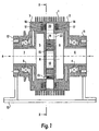
- the liquid ring compressor comprises a cylindrically shaped rotating compressor casing 1.
- the compressor casing comprises two end walls 2,3, which have an orientation substantially vertically to the axis of rotation for the compressor casing.
- On its cylindrical exterior the compressor casing may have ribs as indicated in figure 1 to ensure good heat transfer from the compressor casing to the environment.
- the end walls 2,3 are each mounted round a support bearing 4 and 5 respectively, thus enabling the compressor casing 1 with the end walls 2,3 to rotate about an axis of rotation designated A in the figures.
- the support bearings 4,5 are each mounted on a pedestal 11 and 12 respectively and the pedestals 11 and 12 are affixed to a foundation frame 13.
- the drive unit for the rotating compressor casing is not illustrated in the figures.
- an eccentric piece comprising two cylindrical pipe sockets 6 and 7 affixed to the pedestals 11, 12, each connected to a support bearing 4, 5.
- the pipe sockets' longitudinal direction and centre axes are substantially coincident with the compressor casing's axis of rotation.
- two cylindrical chambers 8 and 9 respectively are affixed. These cylindrical chambers also have centre axes coincident with the compressor casing's axis of rotation.
- a compressor wheel 14 Between the two cylinder chambers 8, 9 there is mounted a compressor wheel 14.
- the compressor wheel 14 is mounted in a freely rotatable manner on a wheel bearing 15, and the wheel bearing 15 is mounted round a shaft journal 10.
- the shaft journal 10 is affixed to the cylinder chambers 8, 9 and has a centre axis designated B in figure 1, parallel to the compressor casing's axis of rotation A, but is eccentrically located relative thereto. This results in the compressor wheel rotating about an axis of rotation B which is eccentric relative to the compressor casing's axis of rotation A.
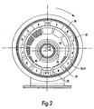
- the compressor wheel 14 comprises twelve radially outwardly protruding vanes 21.
- In the compressor casing is a liquid, which when the compressor casing 1 is rotated, creates a liquid ring 20 along the inner wall of the rotating compressor casing 1.
- the compressor wheel's vanes 21 extend radially outwards and into the liquid ring 20.
- the compressor's compression chambers are defined by the compressor wheel 14, its vanes 21 and the liquid ring 20, and in the direction of the axes of rotation, the compressor casing 1 and the cylinder chambers 8, 9. Due to the compressor wheel's eccentric mounting, the volume of the compression chambers will vary with rotation of the compressor casing 1 and the compressor wheel 14.
- These ports 22, 23 lead from the compression chambers to the two cylindrical chambers, 8 and 9 respectively, where in a normal flow direction a fluid will be conveyed from the cylinder chamber 8, which for the compressor wheel is a suction chamber, through the port 22 into the compression chambers, and the fluid is further conveyed from the compression chambers through the port 23 into the cylinder chamber 9, which is a pressure chamber.
- the device is used as a vacuum pump.
- this magnetic ring 17 may have a centre axis corresponding to the compressor casing's 1 centre axis. Alternatively, the centre axis may be similar to the compressor wheel's 14 centre axis. The size of the magnetic ring is such that it is aligned with the outer parts of the compressor wheel's vanes 21.
- the radial width of the magnetic ring 17 is also such that it is located adjacent to the side of the compressor wheel's vanes 21, along the entire circumference of the magnetic ring, even though the compressor wheel 14 and the magnetic ring 17 have different centre axes.
- magnetic rings are mounted with a steel ring 16, which is located behind, in relation to the compressor wheel on both siides of the compressor wheel.
- the magnetic ring 17 comprises alternate north pole zones 18 and south pole zones 19, and an suitable division of the magnetic ring into north and south pole zones for a compressor wheel with twelve straight vanes is illustrated in the figures.
- the pattern in the magnetic element/ring will vary depending on the number of vanes, and the shape of the vanes.
- the north pole and south pole zones can be applied to the magnetic ring after production in the pattern desired for the compressor concerned.
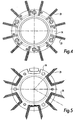
- the vanes 21 are composed of a laminated structure.
- a problem is generally encountered with undesirable heating of the vanes and eddy-currents in the force lines round the magnetic elements.
- the vanes 21 may be formed by constructing a laminated structure parallel to the axis of rotation, as illustrated in figure 3 or by constructing the laminated structure across the axis of rotation as illustrated in figures 4 and 5.
- each vane is constructed with a laminated structure so that the force lines are led from a point on the compressor casing to a second point on the compressor casing on the same side of the compressor casing as the first point.
- the vanes 21 have a laminated structure, which is constructed with a direction across the axis of rotation, with the result that, amongst other things, the force lines can be led from one side of the compressor casing to another side of the compressor casing through the vanes.
- FIG 5 a third and preferred embodiment of the vanes is illustrated, where pairs of vanes are composed of a common laminated element.
- a sheet in the laminated structure extends through one vane, on through a straight portion in the interior of the compressor wheel and out in the second vane, with the result that if the laminated structure element is seen from one side, it forms a U-shaped element.
- the bottom of the U-shaped element is affixed to the compressor wheel and the legs of the U form the vanes.
- the ends of the vanes in this embodiment have been given a sloping termination, thus providing a larger end termination surface for the layers in the laminated structure, which is advantageous for obtaining a good conduction of the force lines.
- vanes in pairs By providing the vanes in pairs in this manner, force lines are also obtained in two directions, through the vane structure from one side to the other side and through the U-shape from one vane to the other vane.
- force lines are also obtained in two directions, through the vane structure from one side to the other side and through the U-shape from one vane to the other vane.
- the U-shape can be disposed in a complementary U-shaped recess in the compressor wheel and secured.
- a holding element of this kind can act as a holding element for one, more or all of the pairs of vanes.
- the laminated structure in the vanes may be composed, for example, of core plates which are varnished on both sides.
- Sheet metal is a very good conductor of force lines and a layer of varnish on the surface of the sheet metal facing a second plate will provide the necessary insulation between the layers of sheet metal.
- Other materials may, of course, be envisaged here both for conducting the force lines and for insulation between the layers. The choice of material will naturally also be dependent on the use of the liquid ring compressor and its size.
- a plurality of compressor wheels may be envisaged mounted in the compressor casing in the longitudinal direction of the axis of rotation, thus providing a multistage compressor unit or there may be several such compressor wheels.
- the inner wall of the compressor casing with inlet and outlet ports and the compressor wheel may be envisaged designed in such a manner that a rotation of the compressor casing gives two "compression cycles" per rotation.
- the liquid ring compressor must be equipped with seals between the individual parts. The choice of type of seal is not dependent on the invention and will be up to a person skilled in the art.
Landscapes
- Engineering & Computer Science (AREA)
- Mechanical Engineering (AREA)
- General Engineering & Computer Science (AREA)
- Structures Of Non-Positive Displacement Pumps (AREA)
- Flanged Joints, Insulating Joints, And Other Joints (AREA)
- Separating Particles In Gases By Inertia (AREA)
- Pharmaceuticals Containing Other Organic And Inorganic Compounds (AREA)
- Applications Or Details Of Rotary Compressors (AREA)
- Rotary Pumps (AREA)
Applications Claiming Priority (3)
| Application Number | Priority Date | Filing Date | Title |
|---|---|---|---|
| NO20023393A NO20023393D0 (no) | 2002-07-12 | 2002-07-12 | V¶skeringkompressor |
| NO20023393 | 2002-07-12 | ||
| PCT/NO2003/000243 WO2004007969A1 (en) | 2002-07-12 | 2003-07-09 | Liquid ring compressor |
Publications (2)
| Publication Number | Publication Date |
|---|---|
| EP1552151A1 EP1552151A1 (en) | 2005-07-13 |
| EP1552151B1 true EP1552151B1 (en) | 2006-03-22 |
Family
ID=19913840
Family Applications (1)
| Application Number | Title | Priority Date | Filing Date |
|---|---|---|---|
| EP03764255A Expired - Lifetime EP1552151B1 (en) | 2002-07-12 | 2003-07-09 | Liquid ring compressor |
Country Status (8)
| Country | Link |
|---|---|
| US (1) | US7066718B2 (no) |
| EP (1) | EP1552151B1 (no) |
| AT (1) | ATE321208T1 (no) |
| AU (1) | AU2003248513A1 (no) |
| DE (1) | DE60304201T2 (no) |
| ES (1) | ES2261969T3 (no) |
| NO (1) | NO20023393D0 (no) |
| WO (1) | WO2004007969A1 (no) |
Families Citing this family (6)
| Publication number | Priority date | Publication date | Assignee | Title |
|---|---|---|---|---|
| WO2006039797A1 (en) * | 2004-10-12 | 2006-04-20 | Led Medical Diagnostics, Inc. | Systems and methods relating to colposcopic viewing tubes for enhanced viewing andexamination |
| WO2009000078A1 (en) * | 2007-06-25 | 2008-12-31 | Led Medical Diagnostics, Inc. | Methods, systems and apparatus relating to colposcopic-type viewing extension devices |
| IL204389A (en) | 2010-03-09 | 2013-07-31 | Agam Energy Systems Ltd | Steam turbine with @ rotating fluid @ and @ method @ using it |
| US10669850B2 (en) * | 2016-12-22 | 2020-06-02 | Brian Blackwell | Impeller-type liquid ring compressor |
| CN117231501A (zh) * | 2023-10-11 | 2023-12-15 | 兰州理工大学 | 一种高效液环真空泵 |
| CN120845341B (zh) * | 2025-09-19 | 2025-11-21 | 江苏长江水泵有限公司 | 一种可旋转泵体结构液环真空泵 |
Family Cites Families (7)
| Publication number | Priority date | Publication date | Assignee | Title |
|---|---|---|---|---|
| US3894812A (en) * | 1974-02-19 | 1975-07-15 | Atlantic Fluidics Inc | Liquid ring vacuum pump-compressor |
| US4050851A (en) * | 1975-11-10 | 1977-09-27 | The Nash Engineering Company | Liquid ring pumps and compressors using a ferrofluidic ring liquid |
| DE3242931A1 (de) * | 1981-05-22 | 1984-05-24 | Hermetic Pumpen Gmbh | Kreiselpumpe mit spaltrohr-magnetkupplungs-antrieb |
| FI103604B1 (fi) * | 1996-08-05 | 1999-07-30 | Rotatek Finland Oy | Nesterengaskone ja menetelmä fluidin siirtämiseksi |
| DE29619930U1 (de) * | 1996-11-15 | 1998-03-19 | SIHI Industry Consult GmbH, 25524 Itzehoe | Flüssigkeitsringverdichter |
| US5722255A (en) * | 1996-12-04 | 1998-03-03 | Brasz; Joost J. | Liquid ring flash expander |
| DE19812976C2 (de) * | 1998-03-24 | 2000-05-04 | Siemens Ag | Flüssigkeitsringverdichter |
-
2002
- 2002-07-12 NO NO20023393A patent/NO20023393D0/no unknown
-
2003
- 2003-07-09 WO PCT/NO2003/000243 patent/WO2004007969A1/en not_active Ceased
- 2003-07-09 EP EP03764255A patent/EP1552151B1/en not_active Expired - Lifetime
- 2003-07-09 AU AU2003248513A patent/AU2003248513A1/en not_active Abandoned
- 2003-07-09 DE DE60304201T patent/DE60304201T2/de not_active Expired - Lifetime
- 2003-07-09 ES ES03764255T patent/ES2261969T3/es not_active Expired - Lifetime
- 2003-07-09 AT AT03764255T patent/ATE321208T1/de not_active IP Right Cessation
- 2003-07-09 US US10/520,709 patent/US7066718B2/en not_active Expired - Fee Related
Also Published As
| Publication number | Publication date |
|---|---|
| AU2003248513A1 (en) | 2004-02-02 |
| US20060039797A1 (en) | 2006-02-23 |
| DE60304201T2 (de) | 2006-12-14 |
| NO20023393D0 (no) | 2002-07-12 |
| ES2261969T3 (es) | 2006-11-16 |
| ATE321208T1 (de) | 2006-04-15 |
| US7066718B2 (en) | 2006-06-27 |
| WO2004007969A1 (en) | 2004-01-22 |
| EP1552151A1 (en) | 2005-07-13 |
| DE60304201D1 (de) | 2006-05-11 |
Similar Documents
| Publication | Publication Date | Title |
|---|---|---|
| EP1101946A3 (en) | Crossing spiral compressor/pump | |
| WO1981001727A1 (en) | Pump having magnetic drive | |
| WO2013114921A1 (ja) | アキシャルギャップ回転子を有する羽根車システム | |
| EP1552151B1 (en) | Liquid ring compressor | |
| CN114623162A (zh) | 一种轴承 | |
| US3291056A (en) | Electric motor pump | |
| US10598221B2 (en) | Permanent magnet thrust bearing | |
| US9745978B2 (en) | Housing for a rotary vane pump | |
| KR100190807B1 (ko) | 마그네트펌프 | |
| EP4361448B1 (en) | Magnetic suspension pump, refrigeration device having same, and air conditioner outdoor unit | |
| WO2021004296A1 (zh) | 压缩机及换热设备 | |
| CN204041464U (zh) | 泵体结构及压缩机 | |
| CN212318783U (zh) | 一种高真空耐高温磁流体密封装置 | |
| CN101331322A (zh) | 斜盘泵的改进 | |
| CN118826372A (zh) | 磁悬浮永磁电机及具有磁悬浮永磁电机的水泵 | |
| CN217029661U (zh) | 一种轴承 | |
| US20190048866A1 (en) | Pump arrangement | |
| CN201062579Y (zh) | 滚动转子式制冷压缩机 | |
| CN2427028Y (zh) | 高温圆筒形同步磁传动器 | |
| CN103062053B (zh) | 异速旋叶压缩机 | |
| CN107630821A (zh) | 电子水泵 | |
| US11522425B2 (en) | Planar high torque electric motor | |
| CN207363896U (zh) | 无冷却高温高压热水泵 | |
| WO2007084014A1 (en) | Enhancements for swash plate pumps | |
| CN207261271U (zh) | 一种工程塑料磁力泵 |
Legal Events
| Date | Code | Title | Description |
|---|---|---|---|
| PUAI | Public reference made under article 153(3) epc to a published international application that has entered the european phase |
Free format text: ORIGINAL CODE: 0009012 |
|
| 17P | Request for examination filed |
Effective date: 20050214 |
|
| AK | Designated contracting states |
Kind code of ref document: A1 Designated state(s): AT BE BG CH CY CZ DE DK EE ES FI FR GB GR HU IE IT LI LU MC NL PT RO SE SI SK TR |
|
| AX | Request for extension of the european patent |
Extension state: AL LT LV MK |
|
| GRAP | Despatch of communication of intention to grant a patent |
Free format text: ORIGINAL CODE: EPIDOSNIGR1 |
|
| DAX | Request for extension of the european patent (deleted) | ||
| GRAS | Grant fee paid |
Free format text: ORIGINAL CODE: EPIDOSNIGR3 |
|
| GRAA | (expected) grant |
Free format text: ORIGINAL CODE: 0009210 |
|
| AK | Designated contracting states |
Kind code of ref document: B1 Designated state(s): AT BE BG CH CY CZ DE DK EE ES FI FR GB GR HU IE IT LI LU MC NL PT RO SE SI SK TR |
|
| PG25 | Lapsed in a contracting state [announced via postgrant information from national office to epo] |
Ref country code: NL Free format text: LAPSE BECAUSE OF FAILURE TO SUBMIT A TRANSLATION OF THE DESCRIPTION OR TO PAY THE FEE WITHIN THE PRESCRIBED TIME-LIMIT Effective date: 20060322 Ref country code: AT Free format text: LAPSE BECAUSE OF FAILURE TO SUBMIT A TRANSLATION OF THE DESCRIPTION OR TO PAY THE FEE WITHIN THE PRESCRIBED TIME-LIMIT Effective date: 20060322 Ref country code: LI Free format text: LAPSE BECAUSE OF FAILURE TO SUBMIT A TRANSLATION OF THE DESCRIPTION OR TO PAY THE FEE WITHIN THE PRESCRIBED TIME-LIMIT Effective date: 20060322 Ref country code: CH Free format text: LAPSE BECAUSE OF FAILURE TO SUBMIT A TRANSLATION OF THE DESCRIPTION OR TO PAY THE FEE WITHIN THE PRESCRIBED TIME-LIMIT Effective date: 20060322 Ref country code: RO Free format text: LAPSE BECAUSE OF FAILURE TO SUBMIT A TRANSLATION OF THE DESCRIPTION OR TO PAY THE FEE WITHIN THE PRESCRIBED TIME-LIMIT Effective date: 20060322 Ref country code: SK Free format text: LAPSE BECAUSE OF FAILURE TO SUBMIT A TRANSLATION OF THE DESCRIPTION OR TO PAY THE FEE WITHIN THE PRESCRIBED TIME-LIMIT Effective date: 20060322 Ref country code: SI Free format text: LAPSE BECAUSE OF FAILURE TO SUBMIT A TRANSLATION OF THE DESCRIPTION OR TO PAY THE FEE WITHIN THE PRESCRIBED TIME-LIMIT Effective date: 20060322 Ref country code: BE Free format text: LAPSE BECAUSE OF FAILURE TO SUBMIT A TRANSLATION OF THE DESCRIPTION OR TO PAY THE FEE WITHIN THE PRESCRIBED TIME-LIMIT Effective date: 20060322 |
|
| REG | Reference to a national code |
Ref country code: GB Ref legal event code: FG4D |
|
| REG | Reference to a national code |
Ref country code: CH Ref legal event code: EP |
|
| REG | Reference to a national code |
Ref country code: IE Ref legal event code: FG4D |
|
| REF | Corresponds to: |
Ref document number: 60304201 Country of ref document: DE Date of ref document: 20060511 Kind code of ref document: P |
|
| PG25 | Lapsed in a contracting state [announced via postgrant information from national office to epo] |
Ref country code: DK Free format text: LAPSE BECAUSE OF FAILURE TO SUBMIT A TRANSLATION OF THE DESCRIPTION OR TO PAY THE FEE WITHIN THE PRESCRIBED TIME-LIMIT Effective date: 20060622 Ref country code: BG Free format text: LAPSE BECAUSE OF FAILURE TO SUBMIT A TRANSLATION OF THE DESCRIPTION OR TO PAY THE FEE WITHIN THE PRESCRIBED TIME-LIMIT Effective date: 20060622 |
|
| PG25 | Lapsed in a contracting state [announced via postgrant information from national office to epo] |
Ref country code: IE Free format text: LAPSE BECAUSE OF NON-PAYMENT OF DUE FEES Effective date: 20060710 |
|
| REG | Reference to a national code |
Ref country code: SE Ref legal event code: TRGR |
|
| PG25 | Lapsed in a contracting state [announced via postgrant information from national office to epo] |
Ref country code: MC Free format text: LAPSE BECAUSE OF NON-PAYMENT OF DUE FEES Effective date: 20060731 |
|
| PG25 | Lapsed in a contracting state [announced via postgrant information from national office to epo] |
Ref country code: PT Free format text: LAPSE BECAUSE OF FAILURE TO SUBMIT A TRANSLATION OF THE DESCRIPTION OR TO PAY THE FEE WITHIN THE PRESCRIBED TIME-LIMIT Effective date: 20060822 |
|
| NLV1 | Nl: lapsed or annulled due to failure to fulfill the requirements of art. 29p and 29m of the patents act | ||
| REG | Reference to a national code |
Ref country code: CH Ref legal event code: PL |
|
| REG | Reference to a national code |
Ref country code: ES Ref legal event code: FG2A Ref document number: 2261969 Country of ref document: ES Kind code of ref document: T3 |
|
| ET | Fr: translation filed | ||
| PLBE | No opposition filed within time limit |
Free format text: ORIGINAL CODE: 0009261 |
|
| STAA | Information on the status of an ep patent application or granted ep patent |
Free format text: STATUS: NO OPPOSITION FILED WITHIN TIME LIMIT |
|
| 26N | No opposition filed |
Effective date: 20061227 |
|
| PG25 | Lapsed in a contracting state [announced via postgrant information from national office to epo] |
Ref country code: GR Free format text: LAPSE BECAUSE OF FAILURE TO SUBMIT A TRANSLATION OF THE DESCRIPTION OR TO PAY THE FEE WITHIN THE PRESCRIBED TIME-LIMIT Effective date: 20060623 Ref country code: CZ Free format text: LAPSE BECAUSE OF FAILURE TO SUBMIT A TRANSLATION OF THE DESCRIPTION OR TO PAY THE FEE WITHIN THE PRESCRIBED TIME-LIMIT Effective date: 20060322 |
|
| PG25 | Lapsed in a contracting state [announced via postgrant information from national office to epo] |
Ref country code: EE Free format text: LAPSE BECAUSE OF FAILURE TO SUBMIT A TRANSLATION OF THE DESCRIPTION OR TO PAY THE FEE WITHIN THE PRESCRIBED TIME-LIMIT Effective date: 20060322 Ref country code: FI Free format text: LAPSE BECAUSE OF FAILURE TO SUBMIT A TRANSLATION OF THE DESCRIPTION OR TO PAY THE FEE WITHIN THE PRESCRIBED TIME-LIMIT Effective date: 20060322 |
|
| PG25 | Lapsed in a contracting state [announced via postgrant information from national office to epo] |
Ref country code: HU Free format text: LAPSE BECAUSE OF FAILURE TO SUBMIT A TRANSLATION OF THE DESCRIPTION OR TO PAY THE FEE WITHIN THE PRESCRIBED TIME-LIMIT Effective date: 20060923 Ref country code: LU Free format text: LAPSE BECAUSE OF NON-PAYMENT OF DUE FEES Effective date: 20060709 Ref country code: TR Free format text: LAPSE BECAUSE OF FAILURE TO SUBMIT A TRANSLATION OF THE DESCRIPTION OR TO PAY THE FEE WITHIN THE PRESCRIBED TIME-LIMIT Effective date: 20060322 |
|
| PG25 | Lapsed in a contracting state [announced via postgrant information from national office to epo] |
Ref country code: CY Free format text: LAPSE BECAUSE OF FAILURE TO SUBMIT A TRANSLATION OF THE DESCRIPTION OR TO PAY THE FEE WITHIN THE PRESCRIBED TIME-LIMIT Effective date: 20060322 |
|
| PGFP | Annual fee paid to national office [announced via postgrant information from national office to epo] |
Ref country code: IT Payment date: 20120131 Year of fee payment: 9 |
|
| PGFP | Annual fee paid to national office [announced via postgrant information from national office to epo] |
Ref country code: FR Payment date: 20130225 Year of fee payment: 10 Ref country code: SE Payment date: 20130122 Year of fee payment: 10 Ref country code: GB Payment date: 20130125 Year of fee payment: 10 Ref country code: DE Payment date: 20130122 Year of fee payment: 10 Ref country code: ES Payment date: 20130123 Year of fee payment: 10 |
|
| REG | Reference to a national code |
Ref country code: SE Ref legal event code: EUG |
|
| GBPC | Gb: european patent ceased through non-payment of renewal fee |
Effective date: 20130709 |
|
| REG | Reference to a national code |
Ref country code: FR Ref legal event code: ST Effective date: 20140331 |
|
| PG25 | Lapsed in a contracting state [announced via postgrant information from national office to epo] |
Ref country code: GB Free format text: LAPSE BECAUSE OF NON-PAYMENT OF DUE FEES Effective date: 20130709 Ref country code: DE Free format text: LAPSE BECAUSE OF NON-PAYMENT OF DUE FEES Effective date: 20140201 Ref country code: SE Free format text: LAPSE BECAUSE OF NON-PAYMENT OF DUE FEES Effective date: 20130710 |
|
| REG | Reference to a national code |
Ref country code: DE Ref legal event code: R119 Ref document number: 60304201 Country of ref document: DE Effective date: 20140201 |
|
| PG25 | Lapsed in a contracting state [announced via postgrant information from national office to epo] |
Ref country code: FR Free format text: LAPSE BECAUSE OF NON-PAYMENT OF DUE FEES Effective date: 20130731 Ref country code: IT Free format text: LAPSE BECAUSE OF NON-PAYMENT OF DUE FEES Effective date: 20130709 |
|
| REG | Reference to a national code |
Ref country code: ES Ref legal event code: FD2A Effective date: 20140807 |
|
| PG25 | Lapsed in a contracting state [announced via postgrant information from national office to epo] |
Ref country code: ES Free format text: LAPSE BECAUSE OF NON-PAYMENT OF DUE FEES Effective date: 20130710 |