EP1552130B1 - Piston assembly and method of manufacture - Google Patents
Piston assembly and method of manufacture Download PDFInfo
- Publication number
- EP1552130B1 EP1552130B1 EP03774795.3A EP03774795A EP1552130B1 EP 1552130 B1 EP1552130 B1 EP 1552130B1 EP 03774795 A EP03774795 A EP 03774795A EP 1552130 B1 EP1552130 B1 EP 1552130B1
- Authority
- EP
- European Patent Office
- Prior art keywords
- piston
- angle
- ring
- wall
- peripheral wall
- Prior art date
- Legal status (The legal status is an assumption and is not a legal conclusion. Google has not performed a legal analysis and makes no representation as to the accuracy of the status listed.)
- Expired - Lifetime
Links
- 238000004519 manufacturing process Methods 0.000 title claims description 6
- 238000000034 method Methods 0.000 title claims description 6
- 230000002093 peripheral effect Effects 0.000 claims description 31
- 238000002485 combustion reaction Methods 0.000 description 8
- 230000006835 compression Effects 0.000 description 4
- 238000007906 compression Methods 0.000 description 4
- 230000000712 assembly Effects 0.000 description 2
- 238000000429 assembly Methods 0.000 description 2
- 239000000567 combustion gas Substances 0.000 description 2
- 239000007789 gas Substances 0.000 description 2
- 238000003754 machining Methods 0.000 description 2
- 239000003570 air Substances 0.000 description 1
- 239000010687 lubricating oil Substances 0.000 description 1
- 239000000463 material Substances 0.000 description 1
- 238000005259 measurement Methods 0.000 description 1
- 239000003921 oil Substances 0.000 description 1
Images

Classifications
-
- F—MECHANICAL ENGINEERING; LIGHTING; HEATING; WEAPONS; BLASTING
- F02—COMBUSTION ENGINES; HOT-GAS OR COMBUSTION-PRODUCT ENGINE PLANTS
- F02F—CYLINDERS, PISTONS OR CASINGS, FOR COMBUSTION ENGINES; ARRANGEMENTS OF SEALINGS IN COMBUSTION ENGINES
- F02F3/00—Pistons
-
- F—MECHANICAL ENGINEERING; LIGHTING; HEATING; WEAPONS; BLASTING
- F16—ENGINEERING ELEMENTS AND UNITS; GENERAL MEASURES FOR PRODUCING AND MAINTAINING EFFECTIVE FUNCTIONING OF MACHINES OR INSTALLATIONS; THERMAL INSULATION IN GENERAL
- F16J—PISTONS; CYLINDERS; SEALINGS
- F16J9/00—Piston-rings, e.g. non-metallic piston-rings, seats therefor; Ring sealings of similar construction
- F16J9/12—Details
- F16J9/20—Rings with special cross-section; Oil-scraping rings
Definitions
- the present invention relates to a piston assembly for an internal combustion engine and in particular to a piston assembly and method of manufacture having a piston ring with two side walls converging at dissimilar angles.
- the piston assembly includes one or more compression rings to generate a seal between the outer surface of the piston and an inner surface of the liner of the combustion chamber.
- An inner end of the compression ring fits into a tapered groove on the outer surface of the piston while an outer wall of the ring makes contact with the inner surface of the liner.
- the outer wall of the compression ring generates the seal in the space between the piston and the liner to prevent high-pressure combustion gases and air from escaping.
- the assembly 10 includes a piston 12 and a piston ring 14.
- the seal formed by the piston ring 14 prevents combustion gases and air from escaping the combustion chamber with each stroke of the piston 12.
- the piston ring 14 includes an inner peripheral wall 20, an outer peripheral wall 22, a first side wall 24 and a second side wall 26.
- the first side wall 24 and the second side wall 26 extend from the inner peripheral wall 20 to the outer peripheral wall 22.
- the prior art piston rings 14 have angles, A, generated by the outward convergence of the side walls 24, 26. In the prior art, the angles, A, are equal, for example, each angle, A, would be approximately 7.5 degrees.
- the piston ring 14 is first machined to generate the two side walls 24, 26 at equal angles, A.
- an additional machining process is necessary to remove the material from the first side wall 24. This additional machining process is time consuming.
- other techniques for generating the beveled intermediate wall such as making the ring 14 from near net shape wire to include the beveled intermediate wall, B, are commonly used in the industry.
- a similar piston ring is shown in JP 03223568 .
- the inventors of the present invention have recognized these and other problems associated with traditional piston assemblies described above. To this end, the inventors have developed a piston assembly including a piston and a piston ring having the twist feature without the need for the beveled intermediate wall.
- the invention comprises a piston assembly comprising a ring and a piston, according to claim 1.
- the invention also describes a method of manufacture for a piston assembly.
- a piston assembly is generally shown at 100. Similar to the prior art, the assembly 100 includes a piston 112 and a piston ring 114.
- the piston assembly 100 is housed within a combustion chamber 116 of an internal combustion engine (not shown). Within the combustion chamber 116 is a cylinder liner 118.
- the ring 114 surrounds the piston 112 and contacts the cylinder liner 118 to form a seal.
- the piston ring 114 includes an inner peripheral wall 120, an outer peripheral wall 122, a first side wall 124 and a second side wall 126.
- the first side wall 124 outwardly converges from the inner peripheral wall 120 to the outer peripheral wall 122.
- first side wall 120 and the first side wall 124 forms a first angle, A14.
- second side wall 126 also outwardly converges from the inner peripheral wall 120 to the outer peripheral wall 122 and the intersection of the inner peripheral wall 120 and the second side wall 126 forms a second angle, A2.
- both the first side wall 124 and the second side wall 126 are linear and approximately equal in length.
- the present invention has the first angle, A1, different from the second angle, A2.
- the first angle, A1 is different than the second angle, A2, by at least one degree. It has been found that the greater the difference between the first angle, A1, and the second angle, A2, the greater the twisting feature that is produced.
- the first angle, A1, would be approximately twelve degrees and the second angle, A2, would be approximately three degrees. The angles of approximately twelve degrees and approximately three degrees are a working example and the invention is in no way limited to these angle measurements.
- the difference between the first angle, A1, and the second angle, A2, produces a twisting feature of the piston ring 114 as best shown in Figure 3 .
- the twisting feature forces an edge 128 of the outer peripheral wall 122 to bear against the liner 118 and provides an effective seal to prevent gases and air from escaping.
- the dissimilar first angle, A1, and second angle, A2 produce this twisting feature, therefore eliminating the need to create an intermediate wall, B, of the traditional prior art piston rings.
- the piston 112 further includes a groove 130 that circumferentially surrounds an outer surface 132 of the piston 112.
- the groove 130 receives the piston ring 114 to create the piston assembly 100.
- the groove 130 has a top wall 134 and a bottom wall 136.
- the top wall 134 extends from a base 138 of the groove 130 to the outer surface 132 of the piston 112 at an angle approximately equal to the first angle, A1, of the piston ring 114.
- the bottom wall 136 extends from the base 138 to the outer surface 132 at an angle approximately equal to the second angle, A2.
- the present invention is also directed toward the method of manufacturing the piston assembly 100.
- the first side wall 124 is formed having the first angle, A1.
- the first side wall 124 forms the first angle, A1, by outwardly converging from the inner peripheral wall 120 to the outer peripheral wall 122.
- the second side wall 126 is formed having the second angle, A2 by outwardly converging from the inner peripheral wall 120 to the outer peripheral wall 122.
- the first angle, A1, and the second angle, A2 are different.
- the ring 114 is inserted into the groove 130 of the piston 112 to form the piston assembly 100.
Landscapes
- Engineering & Computer Science (AREA)
- General Engineering & Computer Science (AREA)
- Mechanical Engineering (AREA)
- Chemical & Material Sciences (AREA)
- Combustion & Propulsion (AREA)
- Pistons, Piston Rings, And Cylinders (AREA)
Description
- The present invention relates to a piston assembly for an internal combustion engine and in particular to a piston assembly and method of manufacture having a piston ring with two side walls converging at dissimilar angles.
- There are traditionally two different types of piston rings, oil control rings and compression rings. Typically, the piston assembly includes one or more compression rings to generate a seal between the outer surface of the piston and an inner surface of the liner of the combustion chamber. An inner end of the compression ring fits into a tapered groove on the outer surface of the piston while an outer wall of the ring makes contact with the inner surface of the liner. The outer wall of the compression ring generates the seal in the space between the piston and the liner to prevent high-pressure combustion gases and air from escaping.
- Typical prior art piston assemblies are shown in
Figures 1a and 1b . Theassembly 10 includes apiston 12 and apiston ring 14. The seal formed by thepiston ring 14 prevents combustion gases and air from escaping the combustion chamber with each stroke of thepiston 12. Thepiston ring 14 includes an innerperipheral wall 20, an outerperipheral wall 22, afirst side wall 24 and asecond side wall 26. Thefirst side wall 24 and thesecond side wall 26 extend from the innerperipheral wall 20 to the outerperipheral wall 22. As shown, the priorart piston rings 14 have angles, A, generated by the outward convergence of theside walls - To improve the seal of the
ring 14, manufacturers have found it desirable to twist thering 14 within atapered groove 30 of apiston 12. Twisting thering 14 causes anedge 28 of the outerperipheral wall 22 of thering 14 to bear against a liner (not shown) with an increased force as compared to the rest of the outerperipheral wall 22. This increased force on theedge 28 of the outerperipheral wall 22 generates a more effective seal and prevents leakage of gases, air and lubricating oils between the liner and the outerperipheral wall 22. Furthermore, twisting thering 14 within thegroove 30 reduces the clearance between thering 14 and thegroove 30 to provide continuity of the seal. To twist thering 14, traditionally thefirst side wall 24 is beveled to generate an intermediate wall, B. The intermediate wall, B permits thering 14 to twist within thetapered piston groove 30 and provide a better seal when contacting the liner and thepiston 12. - To manufacture the
conventional piston ring 14 with the beveled intermediate wall, B, and the resultant twist feature, thepiston ring 14 is first machined to generate the twoside walls first side wall 24. This additional machining process is time consuming. Alternatively, other techniques for generating the beveled intermediate wall, such as making thering 14 from near net shape wire to include the beveled intermediate wall, B, are commonly used in the industry. A similar piston ring is shown inJP 03223568 - The inventors of the present invention have recognized these and other problems associated with traditional piston assemblies described above. To this end, the inventors have developed a piston assembly including a piston and a piston ring having the twist feature without the need for the beveled intermediate wall.
- Specifically, the invention comprises a piston assembly comprising a ring and a piston, according to
claim 1. - The invention also describes a method of manufacture for a piston assembly.
- The present invention will now be described, by way of example, with reference to the accompanying drawings, in which:
-
Figure 1a is an exploded side view of a piston assembly well known in the prior art; -
Figure 1b is an exploded side view of a piston assembly having a beveled intermediate wall well known in the prior art; -
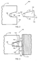
Figure 2 is an exploded side view of a piston assembly of the present invention; and -
Figure 3 is a side view of the piston assembly of the present invention within a combustion chamber of an internal combustion engine. - As seen in
Figures 2 and 3 , a piston assembly is generally shown at 100. Similar to the prior art, theassembly 100 includes apiston 112 and apiston ring 114. Thepiston assembly 100 is housed within acombustion chamber 116 of an internal combustion engine (not shown). Within thecombustion chamber 116 is acylinder liner 118. Thering 114 surrounds thepiston 112 and contacts thecylinder liner 118 to form a seal. Thepiston ring 114 includes an innerperipheral wall 120, an outerperipheral wall 122, afirst side wall 124 and asecond side wall 126. In accordance with the invention, thefirst side wall 124 outwardly converges from the innerperipheral wall 120 to the outerperipheral wall 122. The intersection of the innerperipheral wall 120 and thefirst side wall 124 forms a first angle, A14. Similarly, thesecond side wall 126 also outwardly converges from the innerperipheral wall 120 to the outerperipheral wall 122 and the intersection of the innerperipheral wall 120 and thesecond side wall 126 forms a second angle, A2. Additionally, both thefirst side wall 124 and thesecond side wall 126 are linear and approximately equal in length. - In contrast to the prior art, the present invention has the first angle, A1, different from the second angle, A2. Preferably, the first angle, A1, is different than the second angle, A2, by at least one degree. It has been found that the greater the difference between the first angle, A1, and the second angle, A2, the greater the twisting feature that is produced. For example, the first angle, A1, would be approximately twelve degrees and the second angle, A2, would be approximately three degrees. The angles of approximately twelve degrees and approximately three degrees are a working example and the invention is in no way limited to these angle measurements. The difference between the first angle, A1, and the second angle, A2, produces a twisting feature of the
piston ring 114 as best shown inFigure 3 . The twisting feature forces anedge 128 of the outerperipheral wall 122 to bear against theliner 118 and provides an effective seal to prevent gases and air from escaping. Unlike the prior art, the dissimilar first angle, A1, and second angle, A2, produce this twisting feature, therefore eliminating the need to create an intermediate wall, B, of the traditional prior art piston rings. - The
piston 112 further includes agroove 130 that circumferentially surrounds anouter surface 132 of thepiston 112. Thegroove 130 receives thepiston ring 114 to create thepiston assembly 100. Thegroove 130 has atop wall 134 and abottom wall 136. Thetop wall 134 extends from abase 138 of thegroove 130 to theouter surface 132 of thepiston 112 at an angle approximately equal to the first angle, A1, of thepiston ring 114. Similarly, thebottom wall 136 extends from thebase 138 to theouter surface 132 at an angle approximately equal to the second angle, A2. - The present invention is also directed toward the method of manufacturing the
piston assembly 100. First, thefirst side wall 124 is formed having the first angle, A1. Thefirst side wall 124 forms the first angle, A1, by outwardly converging from the innerperipheral wall 120 to the outerperipheral wall 122. Similarly, thesecond side wall 126 is formed having the second angle, A2 by outwardly converging from the innerperipheral wall 120 to the outerperipheral wall 122. The first angle, A1, and the second angle, A2, are different. Finally, thering 114 is inserted into thegroove 130 of thepiston 112 to form thepiston assembly 100. - It should be understood that the aforementioned and other various alternatives to the embodiments of the invention described herein may be employed in practicing the invention. It is intended that the following claims define the scope of the invention and that the method and apparatus within the scope of these claims be covered thereby.
Claims (4)
- A piston assembly (100), comprising:a ring (114)having an inner peripheral wall (120) and an outer peripheral wall (122);a piston (112) having a groove (130) for receiving said ring (114);said ring (114) further including a first side wall (124) and a second side wall (126), said first side wall (124) outwardly converging at a first angle (A1) from said inner peripheral wall (120) to said outer peripheral wall (122), and said second side wall (126) outwardly converging at a second angle (A2) from said inner peripheral wall (120) to said outer peripheral wall (122);wherein said groove (136) of said piston (112) has top and bottom walls (134, 136), said top wall (134) outwardly converging at a first piston angle (A1) from a base (138) to an outer surface (132), and said bottom wall (134) outwardly converging at a second piston angle (A2), wherein said piston angles (A1, A2) correspond to said ring angles (A1, A2) are approximately equal to said first (A1) and second (A2) angles of said ring (114); andwherein said first piston and ring angles (A1) are different than said second piston and ring angles (A2).
- The piston assembly (100) of claim 1, wherein said first angle (A1) is approximately twelve degrees and said second angle (A2) is approximately three degrees.
- A method of manufacturing a piston assembly (100), comprising the steps of:forming a first side wall (124) having a first angle (A1) outwardly converging from an inner peripheral wall (120) to an outer peripheral wall (122) of a piston ring (114);forming a second side wall (126) having a second angle (A2) outwardly converging from the inner peripheral wall (120) to the outer peripheral wall (122) of the piston ring (114);forming a groove (130) in a piston (112), said groove (130) including a first wall (134) having a third angle (A1) outwardly converging from a base (138) of said groove (130) to an outer surface (132) of said piston (112) and said groove (130) including a second wall (136) having a fourth angle (A2) outwardly converging from said base (138) to said outer surface (132);inserting said piston ring (114) into said groove (130) of said piston (112);whereby said first angle (A1) corresponds to said third angle (A1) and said second angle (A2) corresponds to said fourth angle (A2); andwhereby said first angle (A1) is different than said second angle (A2).
- The method of claim 3, whereby said first angle (A1) is approximately twelve degrees and said second angle (A2) is approximately three degrees.
Applications Claiming Priority (3)
| Application Number | Priority Date | Filing Date | Title |
|---|---|---|---|
| US271109 | 1994-07-06 | ||
| US10/271,109 US7017914B1 (en) | 2002-10-15 | 2002-10-15 | Piston assembly and method of manufacture |
| PCT/US2003/032342 WO2004036019A1 (en) | 2002-10-15 | 2003-10-10 | Piston assembly and method of manufacture |
Publications (2)
| Publication Number | Publication Date |
|---|---|
| EP1552130A1 EP1552130A1 (en) | 2005-07-13 |
| EP1552130B1 true EP1552130B1 (en) | 2014-06-25 |
Family
ID=32106408
Family Applications (1)
| Application Number | Title | Priority Date | Filing Date |
|---|---|---|---|
| EP03774795.3A Expired - Lifetime EP1552130B1 (en) | 2002-10-15 | 2003-10-10 | Piston assembly and method of manufacture |
Country Status (4)
| Country | Link |
|---|---|
| US (1) | US7017914B1 (en) |
| EP (1) | EP1552130B1 (en) |
| AU (1) | AU2003282606A1 (en) |
| WO (1) | WO2004036019A1 (en) |
Families Citing this family (13)
| Publication number | Priority date | Publication date | Assignee | Title |
|---|---|---|---|---|
| BR0104909B1 (en) * | 2001-08-17 | 2010-06-15 | piston for internal combustion engine. | |
| DE10311155A1 (en) * | 2003-03-14 | 2004-09-23 | Gapi Technische Produkte Gmbh | Motor vehicle shaft seal ring has angled inner fluid engaging and support faces and axial sealing face |
| JP4392292B2 (en) * | 2004-06-01 | 2009-12-24 | 住友ゴム工業株式会社 | Compact simple compressor device |
| DE102005037207A1 (en) * | 2005-08-06 | 2007-02-15 | Mahle International Gmbh | Piston ring rotation producing method for internal combustion engine, involves producing asymmetric oil distribution with different oil film profiles in cylinder wall in side of piston periphery during movement of piston hub |
| TW200827558A (en) * | 2006-12-29 | 2008-07-01 | Ind Tech Res Inst | Sealing structure and packing element thereof |
| US20090174150A1 (en) * | 2008-01-08 | 2009-07-09 | Thomas Smith | Lateral side protection of a piston ring with a thermally sprayed coating |
| RU2469231C1 (en) * | 2011-07-27 | 2012-12-10 | Федеральное Государственное Образовательное Учреждение Высшего Профессионального Образования "Саратовский Государственный Аграрный Университет Имени Н.И. Вавилова" | Piston assembly |
| US20130154196A1 (en) * | 2011-12-14 | 2013-06-20 | Mahle International Gmbh | Piston ring formed from ring blank |
| DE102014108973A1 (en) * | 2014-06-26 | 2015-12-31 | Federal-Mogul Burscheid Gmbh | piston ring |
| US10371086B2 (en) | 2016-03-31 | 2019-08-06 | Mahle International Gmbh | Piston ring for improved lubrication oil consumption |
| DE102017105952A1 (en) * | 2017-03-20 | 2018-09-20 | Federal-Mogul Burscheid Gmbh | Flutter-suppression piston ring |
| US11085315B2 (en) * | 2019-07-09 | 2021-08-10 | General Electric Company | Turbine engine with a seal |
| CN220204015U (en) * | 2023-06-16 | 2023-12-19 | 马勒汽车技术(中国)有限公司 | Piston ring |
Family Cites Families (13)
| Publication number | Priority date | Publication date | Assignee | Title |
|---|---|---|---|---|
| US1381993A (en) * | 1919-11-22 | 1921-06-21 | Robert R Hill | Piston-packing |
| US3104594A (en) * | 1960-10-31 | 1963-09-24 | Cummins Engine Co Inc | Piston construction |
| US3831952A (en) * | 1967-02-17 | 1974-08-27 | Sealfire | Piston and piston rings unit for an internal combustion engine |
| US3926166A (en) | 1970-10-01 | 1975-12-16 | Int Harvester Co | Ring manufacture, productive of line contact seal |
| CH560340A5 (en) * | 1973-02-09 | 1975-03-27 | Occident Etablissements | |
| US4123072A (en) | 1977-03-18 | 1978-10-31 | Dana Corporation | Piston ring assembly and method of making same |
| US4299401A (en) | 1979-09-12 | 1981-11-10 | Ramsey Corporation | Piston ring and method of making same |
| US4681326A (en) | 1985-06-10 | 1987-07-21 | Cummins Engine Company, Inc. | Gas lubricated piston ring assembly |
| US4815429A (en) | 1987-06-24 | 1989-03-28 | Combustion Technologies, Inc. | Piston head for an internal combustion engine and a compression ring therefor |
| JP2651944B2 (en) * | 1990-01-26 | 1997-09-10 | 株式会社小松製作所 | Piston with asymmetric full keystone piston ring |
| DE4117212C2 (en) * | 1991-05-27 | 1998-11-26 | Mahle Gmbh | Piston ring for internal combustion engines in the form of a double trapezoidal ring |
| JPH11182679A (en) | 1997-12-24 | 1999-07-06 | Sanshin Ind Co Ltd | Internal combustion engine |
| JP2001182831A (en) * | 1999-12-28 | 2001-07-06 | Nippon Piston Ring Co Ltd | Full keystone type piston ring |
-
2002
- 2002-10-15 US US10/271,109 patent/US7017914B1/en not_active Expired - Fee Related
-
2003
- 2003-10-10 WO PCT/US2003/032342 patent/WO2004036019A1/en not_active Ceased
- 2003-10-10 EP EP03774795.3A patent/EP1552130B1/en not_active Expired - Lifetime
- 2003-10-10 AU AU2003282606A patent/AU2003282606A1/en not_active Abandoned
Also Published As
| Publication number | Publication date |
|---|---|
| US7017914B1 (en) | 2006-03-28 |
| AU2003282606A1 (en) | 2004-05-04 |
| EP1552130A1 (en) | 2005-07-13 |
| WO2004036019A1 (en) | 2004-04-29 |
Similar Documents
| Publication | Publication Date | Title |
|---|---|---|
| US7017914B1 (en) | Piston assembly and method of manufacture | |
| US6357274B1 (en) | Sparkplug manufacturing method | |
| EP1382866A2 (en) | Connecting rod with a split rod-eye | |
| KR20130098350A (en) | Method for producing a piston ring | |
| US6488000B2 (en) | Cylinder block for an internal combustion engine | |
| US11371610B2 (en) | Flutter-suppression piston ring | |
| US20040244758A1 (en) | Method for increasing the displacement of an internal combustion engine and engine having increased displacement thereby | |
| KR20120003891A (en) | Spark ignition device having bridging ground electrode and construction method thereof | |
| US9859688B1 (en) | Remanufactured sparkplug and sparkplug remanufacturing method | |
| US7975601B2 (en) | Engine cylinder liner | |
| US7429048B1 (en) | Piston ring with projection | |
| EP4206498A1 (en) | Combination of piston rings and combined structure of piston and piston rings | |
| JPH05248543A (en) | Cylinder head sealing arrangement for reciprocating piston engine especially internal combustion engine | |
| US11424599B2 (en) | Spark plug with insulator with particular shape | |
| EP0695894B1 (en) | Compression ring for an internal combustion engine | |
| US20230163574A1 (en) | Spark plug for internal combustion engine and method of manufacturing the same | |
| US7172483B2 (en) | Method of making metallic shell for spark plug, method of making spark plug having metallic shell and spark plug produced by the same | |
| JP2010156230A (en) | Engine piston | |
| JP2006017287A (en) | Piston ring for internal combustion engine | |
| US20200284344A1 (en) | Piston ring with inlaid dlc coating and method of manufacturing | |
| US11566581B2 (en) | Steel piston with optimized design | |
| CN216289495U (en) | Solid outer sealing washer, spark plug body, spark plug and vehicle engine | |
| US6837146B2 (en) | Piston for internal combustion engines | |
| US20160208735A1 (en) | Complex-shaped forged piston oil galleries | |
| EP3285344A1 (en) | Spark plug |
Legal Events
| Date | Code | Title | Description |
|---|---|---|---|
| PUAI | Public reference made under article 153(3) epc to a published international application that has entered the european phase |
Free format text: ORIGINAL CODE: 0009012 |
|
| 17P | Request for examination filed |
Effective date: 20050509 |
|
| AK | Designated contracting states |
Kind code of ref document: A1 Designated state(s): AT BE BG CH CY CZ DE DK EE ES FI FR GB GR HU IE IT LI LU MC NL PT RO SE SI SK TR |
|
| AX | Request for extension of the european patent |
Extension state: AL LT LV MK |
|
| DAX | Request for extension of the european patent (deleted) | ||
| RAP1 | Party data changed (applicant data changed or rights of an application transferred) |
Owner name: MAHLE ENGINE COMPONENTS USA, INC. |
|
| 17Q | First examination report despatched |
Effective date: 20081204 |
|
| RAP1 | Party data changed (applicant data changed or rights of an application transferred) |
Owner name: MAHLE INTERNATIONAL GMBH |
|
| GRAP | Despatch of communication of intention to grant a patent |
Free format text: ORIGINAL CODE: EPIDOSNIGR1 |
|
| INTG | Intention to grant announced |
Effective date: 20140115 |
|
| GRAS | Grant fee paid |
Free format text: ORIGINAL CODE: EPIDOSNIGR3 |
|
| GRAA | (expected) grant |
Free format text: ORIGINAL CODE: 0009210 |
|
| AK | Designated contracting states |
Kind code of ref document: B1 Designated state(s): AT BE BG CH CY CZ DE DK EE ES FI FR GB GR HU IE IT LI LU MC NL PT RO SE SI SK TR |
|
| REG | Reference to a national code |
Ref country code: GB Ref legal event code: FG4D |
|
| REG | Reference to a national code |
Ref country code: CH Ref legal event code: EP |
|
| REG | Reference to a national code |
Ref country code: AT Ref legal event code: REF Ref document number: 674870 Country of ref document: AT Kind code of ref document: T Effective date: 20140715 |
|
| REG | Reference to a national code |
Ref country code: IE Ref legal event code: FG4D |
|
| REG | Reference to a national code |
Ref country code: DE Ref legal event code: R096 Ref document number: 60346393 Country of ref document: DE Effective date: 20140807 |
|
| PG25 | Lapsed in a contracting state [announced via postgrant information from national office to epo] |
Ref country code: CY Free format text: LAPSE BECAUSE OF FAILURE TO SUBMIT A TRANSLATION OF THE DESCRIPTION OR TO PAY THE FEE WITHIN THE PRESCRIBED TIME-LIMIT Effective date: 20140625 Ref country code: GR Free format text: LAPSE BECAUSE OF FAILURE TO SUBMIT A TRANSLATION OF THE DESCRIPTION OR TO PAY THE FEE WITHIN THE PRESCRIBED TIME-LIMIT Effective date: 20140926 Ref country code: FI Free format text: LAPSE BECAUSE OF FAILURE TO SUBMIT A TRANSLATION OF THE DESCRIPTION OR TO PAY THE FEE WITHIN THE PRESCRIBED TIME-LIMIT Effective date: 20140625 |
|
| REG | Reference to a national code |
Ref country code: AT Ref legal event code: MK05 Ref document number: 674870 Country of ref document: AT Kind code of ref document: T Effective date: 20140625 |
|
| REG | Reference to a national code |
Ref country code: NL Ref legal event code: VDEP Effective date: 20140625 |
|
| PG25 | Lapsed in a contracting state [announced via postgrant information from national office to epo] |
Ref country code: SE Free format text: LAPSE BECAUSE OF FAILURE TO SUBMIT A TRANSLATION OF THE DESCRIPTION OR TO PAY THE FEE WITHIN THE PRESCRIBED TIME-LIMIT Effective date: 20140625 |
|
| PG25 | Lapsed in a contracting state [announced via postgrant information from national office to epo] |
Ref country code: RO Free format text: LAPSE BECAUSE OF FAILURE TO SUBMIT A TRANSLATION OF THE DESCRIPTION OR TO PAY THE FEE WITHIN THE PRESCRIBED TIME-LIMIT Effective date: 20140625 Ref country code: PT Free format text: LAPSE BECAUSE OF FAILURE TO SUBMIT A TRANSLATION OF THE DESCRIPTION OR TO PAY THE FEE WITHIN THE PRESCRIBED TIME-LIMIT Effective date: 20141027 Ref country code: SK Free format text: LAPSE BECAUSE OF FAILURE TO SUBMIT A TRANSLATION OF THE DESCRIPTION OR TO PAY THE FEE WITHIN THE PRESCRIBED TIME-LIMIT Effective date: 20140625 Ref country code: EE Free format text: LAPSE BECAUSE OF FAILURE TO SUBMIT A TRANSLATION OF THE DESCRIPTION OR TO PAY THE FEE WITHIN THE PRESCRIBED TIME-LIMIT Effective date: 20140625 Ref country code: ES Free format text: LAPSE BECAUSE OF FAILURE TO SUBMIT A TRANSLATION OF THE DESCRIPTION OR TO PAY THE FEE WITHIN THE PRESCRIBED TIME-LIMIT Effective date: 20140625 Ref country code: CZ Free format text: LAPSE BECAUSE OF FAILURE TO SUBMIT A TRANSLATION OF THE DESCRIPTION OR TO PAY THE FEE WITHIN THE PRESCRIBED TIME-LIMIT Effective date: 20140625 |
|
| PG25 | Lapsed in a contracting state [announced via postgrant information from national office to epo] |
Ref country code: NL Free format text: LAPSE BECAUSE OF FAILURE TO SUBMIT A TRANSLATION OF THE DESCRIPTION OR TO PAY THE FEE WITHIN THE PRESCRIBED TIME-LIMIT Effective date: 20140625 Ref country code: AT Free format text: LAPSE BECAUSE OF FAILURE TO SUBMIT A TRANSLATION OF THE DESCRIPTION OR TO PAY THE FEE WITHIN THE PRESCRIBED TIME-LIMIT Effective date: 20140625 |
|
| REG | Reference to a national code |
Ref country code: DE Ref legal event code: R097 Ref document number: 60346393 Country of ref document: DE |
|
| PG25 | Lapsed in a contracting state [announced via postgrant information from national office to epo] |
Ref country code: IT Free format text: LAPSE BECAUSE OF FAILURE TO SUBMIT A TRANSLATION OF THE DESCRIPTION OR TO PAY THE FEE WITHIN THE PRESCRIBED TIME-LIMIT Effective date: 20140625 Ref country code: DK Free format text: LAPSE BECAUSE OF FAILURE TO SUBMIT A TRANSLATION OF THE DESCRIPTION OR TO PAY THE FEE WITHIN THE PRESCRIBED TIME-LIMIT Effective date: 20140625 |
|
| PLBE | No opposition filed within time limit |
Free format text: ORIGINAL CODE: 0009261 |
|
| STAA | Information on the status of an ep patent application or granted ep patent |
Free format text: STATUS: NO OPPOSITION FILED WITHIN TIME LIMIT |
|
| PG25 | Lapsed in a contracting state [announced via postgrant information from national office to epo] |
Ref country code: MC Free format text: LAPSE BECAUSE OF FAILURE TO SUBMIT A TRANSLATION OF THE DESCRIPTION OR TO PAY THE FEE WITHIN THE PRESCRIBED TIME-LIMIT Effective date: 20140625 Ref country code: LU Free format text: LAPSE BECAUSE OF FAILURE TO SUBMIT A TRANSLATION OF THE DESCRIPTION OR TO PAY THE FEE WITHIN THE PRESCRIBED TIME-LIMIT Effective date: 20141010 |
|
| REG | Reference to a national code |
Ref country code: CH Ref legal event code: PL |
|
| 26N | No opposition filed |
Effective date: 20150326 |
|
| REG | Reference to a national code |
Ref country code: IE Ref legal event code: MM4A |
|
| PG25 | Lapsed in a contracting state [announced via postgrant information from national office to epo] |
Ref country code: CH Free format text: LAPSE BECAUSE OF NON-PAYMENT OF DUE FEES Effective date: 20141031 Ref country code: LI Free format text: LAPSE BECAUSE OF NON-PAYMENT OF DUE FEES Effective date: 20141031 |
|
| REG | Reference to a national code |
Ref country code: FR Ref legal event code: PLFP Year of fee payment: 13 |
|
| PG25 | Lapsed in a contracting state [announced via postgrant information from national office to epo] |
Ref country code: IE Free format text: LAPSE BECAUSE OF NON-PAYMENT OF DUE FEES Effective date: 20141010 |
|
| PG25 | Lapsed in a contracting state [announced via postgrant information from national office to epo] |
Ref country code: SI Free format text: LAPSE BECAUSE OF FAILURE TO SUBMIT A TRANSLATION OF THE DESCRIPTION OR TO PAY THE FEE WITHIN THE PRESCRIBED TIME-LIMIT Effective date: 20140625 |
|
| PG25 | Lapsed in a contracting state [announced via postgrant information from national office to epo] |
Ref country code: BG Free format text: LAPSE BECAUSE OF FAILURE TO SUBMIT A TRANSLATION OF THE DESCRIPTION OR TO PAY THE FEE WITHIN THE PRESCRIBED TIME-LIMIT Effective date: 20140625 |
|
| PG25 | Lapsed in a contracting state [announced via postgrant information from national office to epo] |
Ref country code: BE Free format text: LAPSE BECAUSE OF FAILURE TO SUBMIT A TRANSLATION OF THE DESCRIPTION OR TO PAY THE FEE WITHIN THE PRESCRIBED TIME-LIMIT Effective date: 20140625 Ref country code: TR Free format text: LAPSE BECAUSE OF FAILURE TO SUBMIT A TRANSLATION OF THE DESCRIPTION OR TO PAY THE FEE WITHIN THE PRESCRIBED TIME-LIMIT Effective date: 20140625 Ref country code: HU Free format text: LAPSE BECAUSE OF FAILURE TO SUBMIT A TRANSLATION OF THE DESCRIPTION OR TO PAY THE FEE WITHIN THE PRESCRIBED TIME-LIMIT; INVALID AB INITIO Effective date: 20031010 |
|
| REG | Reference to a national code |
Ref country code: FR Ref legal event code: PLFP Year of fee payment: 14 |
|
| REG | Reference to a national code |
Ref country code: FR Ref legal event code: PLFP Year of fee payment: 15 |
|
| REG | Reference to a national code |
Ref country code: FR Ref legal event code: PLFP Year of fee payment: 16 |
|
| PGFP | Annual fee paid to national office [announced via postgrant information from national office to epo] |
Ref country code: FR Payment date: 20181030 Year of fee payment: 16 Ref country code: GB Payment date: 20181031 Year of fee payment: 16 |
|
| PGFP | Annual fee paid to national office [announced via postgrant information from national office to epo] |
Ref country code: DE Payment date: 20191227 Year of fee payment: 17 |
|
| GBPC | Gb: european patent ceased through non-payment of renewal fee |
Effective date: 20191010 |
|
| PG25 | Lapsed in a contracting state [announced via postgrant information from national office to epo] |
Ref country code: FR Free format text: LAPSE BECAUSE OF NON-PAYMENT OF DUE FEES Effective date: 20191031 Ref country code: GB Free format text: LAPSE BECAUSE OF NON-PAYMENT OF DUE FEES Effective date: 20191010 |
|
| REG | Reference to a national code |
Ref country code: DE Ref legal event code: R119 Ref document number: 60346393 Country of ref document: DE |
|
| PG25 | Lapsed in a contracting state [announced via postgrant information from national office to epo] |
Ref country code: DE Free format text: LAPSE BECAUSE OF NON-PAYMENT OF DUE FEES Effective date: 20210501 |