EP1551475B1 - Flow adaptive aspiration tubing and devices - Google Patents
Flow adaptive aspiration tubing and devices Download PDFInfo
- Publication number
- EP1551475B1 EP1551475B1 EP03724661A EP03724661A EP1551475B1 EP 1551475 B1 EP1551475 B1 EP 1551475B1 EP 03724661 A EP03724661 A EP 03724661A EP 03724661 A EP03724661 A EP 03724661A EP 1551475 B1 EP1551475 B1 EP 1551475B1
- Authority
- EP
- European Patent Office
- Prior art keywords
- tubing
- lumen
- flow
- aspiration
- fluid
- Prior art date
- Legal status (The legal status is an assumption and is not a legal conclusion. Google has not performed a legal analysis and makes no representation as to the accuracy of the status listed.)
- Expired - Lifetime
Links
- 230000003044 adaptive effect Effects 0.000 title description 14
- 239000012530 fluid Substances 0.000 claims abstract description 54
- 238000003973 irrigation Methods 0.000 claims description 13
- 230000002262 irrigation Effects 0.000 claims description 13
- 238000004891 communication Methods 0.000 claims description 5
- 230000002708 enhancing effect Effects 0.000 claims description 3
- 230000004048 modification Effects 0.000 abstract description 4
- 238000012986 modification Methods 0.000 abstract description 4
- 210000000695 crystalline len Anatomy 0.000 description 25
- 239000000463 material Substances 0.000 description 17
- 210000002159 anterior chamber Anatomy 0.000 description 15
- 239000012634 fragment Substances 0.000 description 14
- 238000001356 surgical procedure Methods 0.000 description 11
- 230000001965 increasing effect Effects 0.000 description 10
- 239000002775 capsule Substances 0.000 description 8
- 208000002177 Cataract Diseases 0.000 description 7
- 238000000034 method Methods 0.000 description 7
- 239000011824 nuclear material Substances 0.000 description 7
- 230000001054 cortical effect Effects 0.000 description 5
- 238000001125 extrusion Methods 0.000 description 4
- 238000001802 infusion Methods 0.000 description 3
- 230000009021 linear effect Effects 0.000 description 3
- 239000000523 sample Substances 0.000 description 3
- 238000002604 ultrasonography Methods 0.000 description 3
- 230000009471 action Effects 0.000 description 2
- 230000000694 effects Effects 0.000 description 2
- 239000003000 extruded plastic Substances 0.000 description 2
- 239000012528 membrane Substances 0.000 description 2
- 239000002245 particle Substances 0.000 description 2
- 239000004033 plastic Substances 0.000 description 2
- 229920003023 plastic Polymers 0.000 description 2
- 230000009467 reduction Effects 0.000 description 2
- 230000004044 response Effects 0.000 description 2
- 238000010008 shearing Methods 0.000 description 2
- 238000013022 venting Methods 0.000 description 2
- 208000030853 Asthma-Chronic Obstructive Pulmonary Disease Overlap Syndrome Diseases 0.000 description 1
- 201000004569 Blindness Diseases 0.000 description 1
- 206010058202 Cystoid macular oedema Diseases 0.000 description 1
- 206010036346 Posterior capsule opacification Diseases 0.000 description 1
- 206010038848 Retinal detachment Diseases 0.000 description 1
- 230000004075 alteration Effects 0.000 description 1
- 230000003466 anti-cipated effect Effects 0.000 description 1
- 238000013459 approach Methods 0.000 description 1
- 230000008901 benefit Effects 0.000 description 1
- 230000015572 biosynthetic process Effects 0.000 description 1
- 230000008859 change Effects 0.000 description 1
- 210000004087 cornea Anatomy 0.000 description 1
- 230000008878 coupling Effects 0.000 description 1
- 238000010168 coupling process Methods 0.000 description 1
- 238000005859 coupling reaction Methods 0.000 description 1
- 238000010586 diagram Methods 0.000 description 1
- 229910003460 diamond Inorganic materials 0.000 description 1
- 239000010432 diamond Substances 0.000 description 1
- 238000006073 displacement reaction Methods 0.000 description 1
- 239000000839 emulsion Substances 0.000 description 1
- 210000002889 endothelial cell Anatomy 0.000 description 1
- 238000002474 experimental method Methods 0.000 description 1
- 230000002349 favourable effect Effects 0.000 description 1
- 238000013467 fragmentation Methods 0.000 description 1
- 238000006062 fragmentation reaction Methods 0.000 description 1
- ZZUFCTLCJUWOSV-UHFFFAOYSA-N furosemide Chemical compound C1=C(Cl)C(S(=O)(=O)N)=CC(C(O)=O)=C1NCC1=CC=CO1 ZZUFCTLCJUWOSV-UHFFFAOYSA-N 0.000 description 1
- 210000003128 head Anatomy 0.000 description 1
- 239000003978 infusion fluid Substances 0.000 description 1
- 208000014674 injury Diseases 0.000 description 1
- 238000003780 insertion Methods 0.000 description 1
- 230000037431 insertion Effects 0.000 description 1
- 210000003041 ligament Anatomy 0.000 description 1
- 239000007788 liquid Substances 0.000 description 1
- 208000018769 loss of vision Diseases 0.000 description 1
- 231100000864 loss of vision Toxicity 0.000 description 1
- 238000004519 manufacturing process Methods 0.000 description 1
- 238000010297 mechanical methods and process Methods 0.000 description 1
- 238000000465 moulding Methods 0.000 description 1
- 230000009022 nonlinear effect Effects 0.000 description 1
- 230000002093 peripheral effect Effects 0.000 description 1
- 230000002572 peristaltic effect Effects 0.000 description 1
- 229920001296 polysiloxane Polymers 0.000 description 1
- 229920000915 polyvinyl chloride Polymers 0.000 description 1
- 239000004800 polyvinyl chloride Substances 0.000 description 1
- 230000008569 process Effects 0.000 description 1
- 230000000750 progressive effect Effects 0.000 description 1
- 230000000284 resting effect Effects 0.000 description 1
- 230000004264 retinal detachment Effects 0.000 description 1
- 230000003746 surface roughness Effects 0.000 description 1
- 238000012546 transfer Methods 0.000 description 1
- 230000007704 transition Effects 0.000 description 1
- 230000008733 trauma Effects 0.000 description 1
- 230000004393 visual impairment Effects 0.000 description 1
Images

Classifications
-
- F—MECHANICAL ENGINEERING; LIGHTING; HEATING; WEAPONS; BLASTING
- F16—ENGINEERING ELEMENTS AND UNITS; GENERAL MEASURES FOR PRODUCING AND MAINTAINING EFFECTIVE FUNCTIONING OF MACHINES OR INSTALLATIONS; THERMAL INSULATION IN GENERAL
- F16L—PIPES; JOINTS OR FITTINGS FOR PIPES; SUPPORTS FOR PIPES, CABLES OR PROTECTIVE TUBING; MEANS FOR THERMAL INSULATION IN GENERAL
- F16L11/00—Hoses, i.e. flexible pipes
- F16L11/04—Hoses, i.e. flexible pipes made of rubber or flexible plastics
- F16L11/12—Hoses, i.e. flexible pipes made of rubber or flexible plastics with arrangements for particular purposes, e.g. specially profiled, with protecting layer, heated, electrically conducting
- F16L11/121—Hoses, i.e. flexible pipes made of rubber or flexible plastics with arrangements for particular purposes, e.g. specially profiled, with protecting layer, heated, electrically conducting specially profiled cross sections
-
- A—HUMAN NECESSITIES
- A61—MEDICAL OR VETERINARY SCIENCE; HYGIENE
- A61M—DEVICES FOR INTRODUCING MEDIA INTO, OR ONTO, THE BODY; DEVICES FOR TRANSDUCING BODY MEDIA OR FOR TAKING MEDIA FROM THE BODY; DEVICES FOR PRODUCING OR ENDING SLEEP OR STUPOR
- A61M1/00—Suction or pumping devices for medical purposes; Devices for carrying-off, for treatment of, or for carrying-over, body-liquids; Drainage systems
- A61M1/71—Suction drainage systems
- A61M1/77—Suction-irrigation systems
-
- A—HUMAN NECESSITIES
- A61—MEDICAL OR VETERINARY SCIENCE; HYGIENE
- A61M—DEVICES FOR INTRODUCING MEDIA INTO, OR ONTO, THE BODY; DEVICES FOR TRANSDUCING BODY MEDIA OR FOR TAKING MEDIA FROM THE BODY; DEVICES FOR PRODUCING OR ENDING SLEEP OR STUPOR
- A61M1/00—Suction or pumping devices for medical purposes; Devices for carrying-off, for treatment of, or for carrying-over, body-liquids; Drainage systems
- A61M1/84—Drainage tubes; Aspiration tips
-
- F—MECHANICAL ENGINEERING; LIGHTING; HEATING; WEAPONS; BLASTING
- F16—ENGINEERING ELEMENTS AND UNITS; GENERAL MEASURES FOR PRODUCING AND MAINTAINING EFFECTIVE FUNCTIONING OF MACHINES OR INSTALLATIONS; THERMAL INSULATION IN GENERAL
- F16L—PIPES; JOINTS OR FITTINGS FOR PIPES; SUPPORTS FOR PIPES, CABLES OR PROTECTIVE TUBING; MEANS FOR THERMAL INSULATION IN GENERAL
- F16L9/00—Rigid pipes
- F16L9/006—Rigid pipes specially profiled
-
- A—HUMAN NECESSITIES
- A61—MEDICAL OR VETERINARY SCIENCE; HYGIENE
- A61F—FILTERS IMPLANTABLE INTO BLOOD VESSELS; PROSTHESES; DEVICES PROVIDING PATENCY TO, OR PREVENTING COLLAPSING OF, TUBULAR STRUCTURES OF THE BODY, e.g. STENTS; ORTHOPAEDIC, NURSING OR CONTRACEPTIVE DEVICES; FOMENTATION; TREATMENT OR PROTECTION OF EYES OR EARS; BANDAGES, DRESSINGS OR ABSORBENT PADS; FIRST-AID KITS
- A61F9/00—Methods or devices for treatment of the eyes; Devices for putting in contact-lenses; Devices to correct squinting; Apparatus to guide the blind; Protective devices for the eyes, carried on the body or in the hand
- A61F9/007—Methods or devices for eye surgery
- A61F9/00736—Instruments for removal of intra-ocular material or intra-ocular injection, e.g. cataract instruments
-
- A—HUMAN NECESSITIES
- A61—MEDICAL OR VETERINARY SCIENCE; HYGIENE
- A61M—DEVICES FOR INTRODUCING MEDIA INTO, OR ONTO, THE BODY; DEVICES FOR TRANSDUCING BODY MEDIA OR FOR TAKING MEDIA FROM THE BODY; DEVICES FOR PRODUCING OR ENDING SLEEP OR STUPOR
- A61M2206/00—Characteristics of a physical parameter; associated device therefor
- A61M2206/10—Flow characteristics
-
- A—HUMAN NECESSITIES
- A61—MEDICAL OR VETERINARY SCIENCE; HYGIENE
- A61M—DEVICES FOR INTRODUCING MEDIA INTO, OR ONTO, THE BODY; DEVICES FOR TRANSDUCING BODY MEDIA OR FOR TAKING MEDIA FROM THE BODY; DEVICES FOR PRODUCING OR ENDING SLEEP OR STUPOR
- A61M2210/00—Anatomical parts of the body
- A61M2210/06—Head
- A61M2210/0612—Eyes
Definitions
- the present invention relates generally to apparatus for performing phacoemulsification, in particular to flow adaptive aspiration tubing for use in conjunction with phacoemulsification systems.
- the crystalline lens of the human eye transmits and focuses light and is located behind the iris attached to the wall of the eye by suspensory ligaments known as the zonules.
- the lens consists of a more rigid central nucleus surrounded by peripheral cortical material, which has a softer consistency.
- a fine membrane known as the capsule contains the entire lens.
- Cataract formation refers to a loss of transparency of the crystalline lens of the eye and is a common occurrence with age. This results in a progressive reduction in vision, which can be restored with surgery.
- Cataract surgery involves removal of the cataractous lens and insertion of a plastic intraocular lens to replace the crystalline lens. Removal of the cataractous lens is accomplished using ultrasonic energy to fragment and aspirate the lens by a technique known as phacoemulsification.
- a central opening is formed in the anterior portion of the capsule to permit access to the lenticular material.
- An ultrasonic handpiece typically including a needle having an outer wall and central lumen, is then inserted, contacted against and caused to fragment the lens.
- An elastomeric sleeve surrounding the needle provides a conduit irrigating the eye to replace material aspirated through the needle.
- the anterior chamber In both phases of the procedure it is important that the anterior chamber is maintained at a positive pressure and constant volume to prevent collapse, so as to prevent trauma to sensitive ocular tissues.
- Contact with the endothelial cells lining the posterior surface of the cornea or the iris can result in irreparable damage.
- Even more common is inadvertent contact or aspiration of the posterior capsule, which prevents the escape of the fluid contained in the posterior chamber of the eye known as the vitreous humour. Such inadvertent contact may result in rupture of the posterior capsule membrane.
- the anterior chamber pressure preferably should be maintained at a constant level to avoid alterations in chamber volume, which manifest as an unstable chamber during surgery.
- a conventional apparatus used in cataract surgery includes a console containing a pump system used to generate vacuum and flow as well as the electrical circuitry that provides, energy and control for the phacoemulsification handpiece.
- the pump systems are connected to the phacoemulsification handpiece and irrigation and aspiration cannula by tubing so that fluid and lens material can be aspirated from the eye.
- the first type are positive fluid displacement pumps, such as a peristaltic pump.
- fluid flow is generated by drawing suction through the tubing and significant vacuum may be achieved if the tubing becomes occluded.
- suction is generated in a cassette and the subsequent flow and aspiration of fluid from the eye is related to that preset suction level.
- Fluid is aspirated from the anterior chamber via suction applied through the phacoemulsification needle or irrigation/aspiration cannula and the associated aspiration tubing. This suction attracts nuclear or cortical material to the needle or cannula and may result in larger fragments occluding the tip or aspiration port.
- Vacuum applied by the phacoemulsification handpiece may be modulated by foot pedal control, thereby causing the pump system to respond by venting or equalizing the pressure in the system either to fluid or to air.
- the venting occurs, some distance from the handpiece and anterior chamber and there is typically a lag before the vacuum in the tubing is restored to a positive pressure and the pressure in the anterior chamber is restored to the normal resting or unoccluded level.
- One potential method for reducing fluid surges in the aspiration tubing is to reduce the maximum vacuum levels that are generated by the pump system.
- High vacuum levels are advantageous in capturing fragments of nuclear material so that the fragments may be fractured into smaller pieces. It is therefore desirable to maintain high vacuum levels while reducing the high flow rates associated with surges that occur at those high levels of vacuum.
- Another approach is to increase the resistance in the aspiration tubing by reducing the lumen or increasing the length of the aspiration tubing. While reducing the lumen size may be effective, the internal diameter of typical phacoemulsification tubing is generally about 1.5 mm, and any further reduction in diameter is likely to result in obstruction of the aspiration tubing by lens material. Increasing the tubing length may be accomplished by coiling the tubing to add further hydrodynamic resistance. In both cases, however, the increased resistance of the tubing exists for all vacuum levels. This is undesirable, as it would be preferable to maintain undiminished aspirational flow rates at low vacuum levels to facilitate attraction of lens fragments prior to occlusion.
- the device has a hand piece with an ultrasonic generator. It has a hollow needle with a hole in its lower end. The debris is sucked through a tube in the hand piece that is joined to a suction pump. A radial hole in the wall of the needle allows liquid to circulate between the end of the needle and the pump even if the lower hole is obstructed. The distance between the radial hole and the point of the needle is greater than the maximum length of a piece of debris.
- the DE 196 51 676 A1 describes a hollow needle for an instrument for performing a phacoemulsification for the fragmentation of eye lens and for the suction up emulsion of infusion fluid an lens residue.
- the hollow needle is provided with a cannula which has an operating end for the eye lens and a lumen section.
- a wider section is connected to the lumen part of the cannula near its operating end.
- the internal cross section surface of the cannula is larger inside the wider part than in the lumen part.
- the wider part is formed by single cylindrical expansion duct whose diameter is larger than the diameter of the lumen part,
- the expansion duct is concentric with the lumen part of the cannula.
- the inner surface of the expansion duct leads via a radial transfer surface into the inner surface of the lumen part of the cannula.
- the DE 196 28 252 A1 further describes a probe for removal of eye tissue.
- the probe has an ultrasound source connected to a phacoemulsification needle.
- the needle has a central lumen within it which acts as a suction channel which has a funnel shaped end for the removal of the pulverised pieces of eye material caused by the probe end.
- the suction channel has projections on its inner wall in an area extending from the opening of the needle point. The projections can be arranged either symmetrically or non-symmetrically around the section lumen and extend back into the lumen in lines.
- WO 02/19896 A2 describes a surge-flow regulator for use with an ophthalmic surgical instrument having an infusion line adapted to irrigate a surgical site with fluid and an aspiration line adapted to carry the fluid and particles of lenticular debris away from the surgical site.
- the surge-flow regulator includes a flow limiting device that is placed in fluid communication with the aspiration line to control surge-flow of the aspirated fluid and lenticular debris through the aspiration line.
- the lenticular debris carried in the aspiration line. The processed into smaller particles before the fluid and debris are introduced to the flow limiting device.
- US 2002/022810 A1 discloses a non-linear flow restrictor that limits the maximum flow rate in a medical aspiration system.
- the flow restrictor changes the direction of fluid flow to generate non-linear effects in the fluid. This creates a non-linear relationship between the pressure within the system and the flow rate of the fluid.
- the non-linear relationship may define a pressure versus flow rate curve that has a flat portion where the flow rate does not increase with an increase in pressure.
- a phacoemulsification system including flow adaptive aspiration tubing that automatically increases flow resistance in response to higher flow rates.
- phacoemulsification system including flow adaptive aspiration tubing that provides improved anterior chamber stability at higher vacuum levels.
- a phacoemulsification system including flow adaptive aspiration tubing that automatically increases flow resistance in response to higher flow rates.
- a phacoemulsification system constructed in accordance with the principles of the present invention comprises the features specified in claim 1.
- the topographical features may be provided along the entire length of the tubing or only along discrete portions of the length, and may extend around the entire circumference of the lumen or only parts thereof.
- Phacoemulsification system 10 comprises phacoemulsification needle 11 coupled to ultrasonic handpiece 20 and surrounded by elastomeric sleeve 12.
- Handpiece 20 is typically coupled to a controller (not shown), that causes needle 11 to vibrate at ultrasonic frequencies.
- vibration of needle 11 causes the needle to fragment the nuclear material of the lens.
- Irrigation line 13 is coupled in fluid communication between a source of irrigation fluid 14 and handpiece 20 so that irrigation fluid is delivered into the eye via annulus 15 formed between needle 11 and interior surface 16 of elastomeric sleeve 12.
- Aspiration tubing 17 is coupled in fluid communication between lumen 18 of needle 11 and vacuum source 19, to permit the aspiration of fragmented nuclear material from a patient's eye.
- ultrasound energy is applied to the nuclear material of the patient's lens by phacoemulsification needle 11.
- irrigation fluid is supplied to the eye from irrigation reservoir 14 via annulus 15 between needle 11 and elastomeric sleeve 12.
- fragmented nuclear material is withdrawn through needle lumen 18 and aspiration tubing 17.
- larger fragments that are caused to engage needle 11 by virtue of suction drawn through lumen 18 may cause surges in flow rates of material aspirated through lumen 18 and wide fluctuations of the pressure within the eye.
- the aspiration tubing of the present invention is expected to moderate such post-occlustion surges and reduce the resulting pressure fluctuations.
- phacoemulsification system 10 of FIG. 1 is provided with aspiration tubing having a lumen modified to enhance hydrodynamic resistance to fluid flow at higher flow rates.
- the modification may take one of a number of forms, and comprise topographic features along the interior surface of the tubing, freely-movable obstructions within the flow path, or one or more flow redirecting bends.
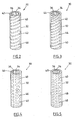
- Tubing 30 has outer surface 32 and inner surface 34 that defines lumen 36.
- inner surface 34 comprises topographical features 40 that enhance flow resistance at higher flow rates by enhancing turbulent flow within the lumen.
- Features 40 may be provided along the entire length of the tubing or only along one or more discrete segments of the tubing. In addition, the features may extend entirely around the circumference of tubing 30 as shown in FIG. 2 , or may extend for only limited arcs of the circumference.
- features 40 comprise spiral flutes or recesses 42 formed as grooves in the inner surface of the tubing.
- Recesses 42 illustratively are disposed at regular intervals along the length of the tubing and around the circumferential periphery of the inner surface.
- Recesses 42 may have a semi-annular cross-section (as shown in FIG. 2 ) or alternatively may include a cross-sectional profile of a semi-ellipse, rectangular, triangular, square, diamond or other suitable shape.
- recesses 42 produce turbulent flow within lumen 36 without increasing the likelihood that a large fragment will obstruct the lumen.
- recesses 40 enhanced turbulence by increasing the hydrodynamic resistance of fluid passing through the tubing.
- features 40 alter the flow pattern within the lumen such that the flow becomes turbulent at lower flow velocities.
- topographical features 40 comprise raised protuberances 44, such as ridges or lugs, that project from the inner surface of tubing into lumen 36.
- Protuberances 44 may be arranged as a series of semi-cylindrical ridges disposed in a spiral pattern at regular intervals along the length of the tubing and around the circumferential periphery of lumen 36.
- protuberances 44 may extend only partially around the circumference of lumen 36, or only along selected portions of the tubing length.
- protuberances 44 enhance hydrodynamic resistance within tubing 30 and induce turbulent flow at lower flow velocities and vacuum levels than otherwise encountered in previously known aspiration tubing.
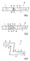
- topographical features 40 comprise longitudinal recesses 46 ( FIG. 4 ) or longitudinal protuberances 48 ( FIG. 5 ) formed in the inner surface of tubing 30.
- Longitudinal recesses 46 or protuberances 48 are shown disposed substantially parallel to each other and spaced at regular intervals around the circumferential periphery of lumen 36.
- recesses 46 or protuberances 48 may extend only partially around the circumference of lumen 36, or only along selected portions of the tubing length.
- aspiration tubing 30 comprises a freely-moving object 50, illustratively, a vane or propeller, disposed within lumen 36.
- Object 50 is configured to fit within tubing 30 so that it disrupts laminar flow of fluid within lumen 36 and induces turbulence.
- laminar flow is indicated by straight arrow L
- turbulent flow is indicated by curved arrow T.
- the induced turbulence increases hydrodynamic resistance within lumen 36, and is a function of the flow velocity within the tubing.
- freely-moving object 50 may comprise vane 56 ( FIG. 6 ) mounted within lumen 36 on hub 58 and having a plurality of arms 60.
- freely-moving object 50 may comprise propeller 62 having a plurality of projections 63.
- Propeller 62 is mounted on axle 64 supported on arms 65 within lumen 66 of separate short longitudinal segment 67.
- segment 67 includes adapters 68 at either end so that freely-moving object 50 may be used in conjunction with previously-known aspiration tubing.
- freely-moving object 50 may take on other shapes.
- flow through the aspiration tubing may be modified using more than one freely-moving object to disrupt laminar flow.
- aspiration tubing 30 comprises one or more angular bends 70. Bends 70 cause abrupt changes in the direction of fluid flowing with in lumen 72, so that an initially laminar flow (as indicated by straight arrow L) becomes turbulent flow (as indicated by curved arrow T) after the fluid passes through the one or more angular bends. Preferably, the bend angles are less than or equal to 90°. As for the example of FIG. 7 , the example of FIG. 8 may be implemented as a separate segment of rigid tubing that includes one or more bends, and adapters for coupling the segment in-line with previously-known aspiration tubing.
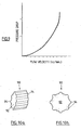
- the resistance afforded to fluid flow by the modified aspiration tubing will be relatively unchanged at low vacuum levels but increases proportionally as the vacuum levels rise due to the transition from laminar to turbulent flow (which occurs at lower vacuum level than in previously-known tubing with a smooth internal surface).
- the drop in pressure due to flow resistance varies as the square of the velocity. Therefore, as depicted in FIG. 9 , the drop in pressure plotted against the velocity of fluid flow forms a parabola, wherein a relatively small change in fluid velocity results from a relatively large percentage drop in pressure compared to tubing with a lower frictional resistance and laminar flow.
- the provision of topographical features on the inner surface of the tubing does not reduce the efficiency of the phacoemulsification needle in attracting fragments of nuclear material.
- the initial rise in vacuum within the tubing is similar to previously-known tubing, but the rise time slows as the vacuum level is increased.
- the occlusion resistance is overcome, the immediate flow of fluid due to the negative pressure in the aspiration line will be less than with previously-known tubing.
- this reduces both the magnitude and duration of post-occlusion surge.
- the present invention provides modified aspiration tubing with increased flow resistance at higher vacuum levels. This provides a more stable anterior chamber pressure and volume than that encountered with previously-known aspiration tubing.
- the aspiration tubing of the present invention enables higher vacuum levels to be employed during phacoemulsification. Higher vacuum levels increase the attraction of nuclear fragments to the needle tip and facilitate the fracture of the fragments into smaller pieces by a second instrument.
- the cross sectional area and the length of the modified aspiration tubing can be formed to be the same as with previously-known aspiration tubing, the likelihood of obstruction by fragments of lens material, is not increased.
- Previously-known aspiration tubing may be formed from extruded plastic materials, wherein the unpolymerized plastic flows out through a conical extrusion nozzle provided with a central die.
- the shape of the die determines the cross-sectional profile of the internal lumen of the aspiration tubing and is usually cylindrical in form.
- the speed of extrusion and relationship between the central die and surrounding nozzle determines the wall thickness.
- Die 90 resembles a gear and has central cylindrical portion 92 and a plurality of semi-circular protuberances 94 spaced at substantially equal intervals around its outer periphery.
- Die 90 By rotating the extruded plastic material as it exits the extrusion nozzle, a spiral pattern of grooves or flutes is formed in the internal surface of the lumen. The speed of rotation determines the pitch of the spiral pattern.
- Suitable materials for manufacturing the aspiration tubing of the present invention include polyvinyl chloride and silicones.
- the modified aspiration tubing can be fabricated by other methods than the above-described extruded molding method without departing from the scope of the present invention.
- the modified spiral fluted aspiration tubing of the present invention has an internal diameter of about 1.5 mm and an external diameter of about 3.1.2 mm. It should be noted that tubing with a lumen having an internal diameter of 1.34 mm and 8 equally-spaced flutes with a radius of 0.173 mm will have the same total cross sectional area as previously-known tubing with a lumen having an internal diameter of 1.5 mm.
- the modified aspiration tubing of the present invention may be constructed with similar connectors attached to the proximal and distal ends as previously-known tubing, and thus have the same overall length.
- the modified aspiration tubing also may be used with any method of cataract removal where other energy sources such as laser, sonic, rotary tips, impellers, hydro jet and mechanical methods are used to fragment the cataract and the lens material is removed by aspiration.
- the modified aspiration tubing may be advantageously employed in other medical applications wherein fluids or tissues are aspirated.
- the entire length of aspiration tubing may include the modified lumen.
- the modified aspiration tubing may be formed as either a flexible or rigid segment that may be inserted into a previously-known aspiration line as a separate device.
- a three-way tap may be provided within the aspiration line to permit bypass or inclusion of the modified aspiration tubing in the aspiration circuit, and thereby alter the rate of fluid flow within an internal lumen of the aspiration line.
Landscapes
- Health & Medical Sciences (AREA)
- Engineering & Computer Science (AREA)
- Heart & Thoracic Surgery (AREA)
- General Engineering & Computer Science (AREA)
- General Health & Medical Sciences (AREA)
- Public Health (AREA)
- Vascular Medicine (AREA)
- Anesthesiology (AREA)
- Biomedical Technology (AREA)
- Hematology (AREA)
- Life Sciences & Earth Sciences (AREA)
- Animal Behavior & Ethology (AREA)
- Mechanical Engineering (AREA)
- Veterinary Medicine (AREA)
- Pulmonology (AREA)
- Surgery (AREA)
- External Artificial Organs (AREA)
- Infusion, Injection, And Reservoir Apparatuses (AREA)
- Electric Cable Installation (AREA)
- Pipe Accessories (AREA)
- Surgical Instruments (AREA)
- Mechanical Treatment Of Semiconductor (AREA)
- Glass Compositions (AREA)
- Media Introduction/Drainage Providing Device (AREA)
Applications Claiming Priority (3)
| Application Number | Priority Date | Filing Date | Title |
|---|---|---|---|
| AUPS2801A AUPS280102A0 (en) | 2002-06-07 | 2002-06-07 | Aspiration tubing |
| AUPS280102 | 2002-06-07 | ||
| PCT/AU2003/000703 WO2003103746A1 (en) | 2002-06-07 | 2003-06-06 | Flow adaptive aspiration tubing and devices |
Publications (3)
| Publication Number | Publication Date |
|---|---|
| EP1551475A1 EP1551475A1 (en) | 2005-07-13 |
| EP1551475A4 EP1551475A4 (en) | 2008-05-28 |
| EP1551475B1 true EP1551475B1 (en) | 2011-12-14 |
Family
ID=3836363
Family Applications (1)
| Application Number | Title | Priority Date | Filing Date |
|---|---|---|---|
| EP03724661A Expired - Lifetime EP1551475B1 (en) | 2002-06-07 | 2003-06-06 | Flow adaptive aspiration tubing and devices |
Country Status (8)
| Country | Link |
|---|---|
| US (1) | US7727179B2 (enExample) |
| EP (1) | EP1551475B1 (enExample) |
| JP (1) | JP2005528957A (enExample) |
| CN (1) | CN1658915A (enExample) |
| AT (1) | ATE536899T1 (enExample) |
| AU (1) | AUPS280102A0 (enExample) |
| CA (1) | CA2487818A1 (enExample) |
| WO (1) | WO2003103746A1 (enExample) |
Cited By (1)
| Publication number | Priority date | Publication date | Assignee | Title |
|---|---|---|---|---|
| US8777931B2 (en) | 2011-08-19 | 2014-07-15 | Alcon Research, Ltd. | Retractable luer lock fittings |
Families Citing this family (69)
| Publication number | Priority date | Publication date | Assignee | Title |
|---|---|---|---|---|
| US7803141B2 (en) * | 2003-08-12 | 2010-09-28 | Boston Scientific Scimed, Inc. | Device and method for direct delivery of a therapeutic using non-newtonian fluids |
| WO2005094283A2 (en) | 2004-03-25 | 2005-10-13 | Hauser David L | Vascular filter device |
| GB0423422D0 (en) * | 2004-10-21 | 2004-11-24 | Bard Inc C R | Medical device for fluid flow, and method of forming such device |
| CH697759B1 (de) | 2004-11-24 | 2009-02-13 | Oertli Instr Ag | Nadel für eine Vorrichtung zur Phacoemulsifikation. |
| CH697769B1 (de) | 2004-11-24 | 2009-02-13 | Oertli Instr Ag | Nadel für eine Vorrichtung zur Phacoemulsifikation. |
| US8241242B2 (en) * | 2005-03-30 | 2012-08-14 | Abbott Medical Optics Inc. | Phacoaspiration flow restrictor with bypass tube |
| US20100130937A1 (en) * | 2005-06-30 | 2010-05-27 | Abbott Vascular Inc. | Introducer sheath and methods of making |
| US8440122B2 (en) | 2005-06-30 | 2013-05-14 | Abbott Vascular Inc. | Introducer sheath and methods of making |
| US8359723B2 (en) | 2005-06-30 | 2013-01-29 | Abbott Vascular Inc. | Introducer sheath and methods of making |
| US9352118B2 (en) * | 2005-06-30 | 2016-05-31 | Abbott Laboratories | Modular introducer and exchange sheath |
| US9597063B2 (en) * | 2006-06-28 | 2017-03-21 | Abbott Laboratories | Expandable introducer sheath to preserve guidewire access |
| US20080004571A1 (en) * | 2006-06-28 | 2008-01-03 | Abbott Laboratories | Expandable introducer sheath |
| US9168359B2 (en) | 2005-06-30 | 2015-10-27 | Abbott Laboratories | Modular introducer and exchange sheath |
| US20070078440A1 (en) * | 2005-07-21 | 2007-04-05 | Perkins James T | Thin wall surgical irrigation tubing with longitudinal reinforcements |
| US20070032777A1 (en) * | 2005-07-21 | 2007-02-08 | Perkins James T | Concentric thin wall surgical irrigation tubing |
| US20070149919A1 (en) * | 2005-07-21 | 2007-06-28 | Bausch & Lomb Incorporated | Concentric thin wall surgical irrigation tubing |
| US20070149950A1 (en) * | 2005-07-21 | 2007-06-28 | Bausch & Lomb Incorporated | Thin wall surgical irrigation tubing with longitudinal reinforcements |
| US9889275B2 (en) | 2006-06-28 | 2018-02-13 | Abbott Laboratories | Expandable introducer sheath to preserve guidewire access |
| US20100198160A1 (en) * | 2006-06-28 | 2010-08-05 | Abbott Vascular Inc. | Expandable Introducer Sheaths and Methods for Manufacture and Use |
| US7981074B2 (en) * | 2006-11-02 | 2011-07-19 | Novartis Ag | Irrigation/aspiration system |
| US8333741B2 (en) * | 2006-11-10 | 2012-12-18 | Bausch & Lomb Incorporated | Phacoemulsification cannula with improved purchase |
| US20080200884A1 (en) * | 2007-02-20 | 2008-08-21 | Perkins James T | Thin wall surgical irrigation tubing with longitudinal reinforcements |
| US8753323B2 (en) * | 2007-06-13 | 2014-06-17 | Dana, LLC. | Vacuum surge suppressor for surgical aspiration systems |
| US8721594B2 (en) * | 2007-06-19 | 2014-05-13 | Alcon Research, Ltd. | Post-occlusion chamber collapse canceling system for a surgical apparatus and method of use |
| US20080319451A1 (en) * | 2007-06-21 | 2008-12-25 | Jaime Zacharias | Post-occlusion chamber collapse suppressing system for a surgical apparatus and method of use |
| DE102007031618B3 (de) * | 2007-07-06 | 2008-12-18 | Carl Zeiss Surgical Gmbh | Durchflussbegrenzer für ein in einem Aspirationszweig für ein chirurgisches System strömendes Fluid und chirurgisches System |
| US8631831B2 (en) * | 2008-09-04 | 2014-01-21 | Alcon Research, Ltd. | Multi-compliant tubing |
| US9149387B2 (en) * | 2008-09-04 | 2015-10-06 | Novartis Ag | Varying material properties of a single fluidic line in ophthalmology tubing |
| US20100130944A1 (en) * | 2008-11-21 | 2010-05-27 | Music Douglas E | Flow control devices for ophthalmic surgery |
| US7819837B2 (en) * | 2008-12-11 | 2010-10-26 | Bausch & Lomb Incorporated | Device for controlling flow rate of aspirated fluids |
| US8801653B2 (en) * | 2009-06-04 | 2014-08-12 | Armand Maaskamp | Surgical apparatus and methods asociated therewith |
| EP2525849B1 (en) * | 2010-01-23 | 2019-09-18 | Duke University | Jetless intravenous catheter |
| CN101843523A (zh) * | 2010-05-28 | 2010-09-29 | 浙江舒友仪器设备有限公司 | 一种高频手术刀 |
| EP2600940A1 (en) * | 2010-08-02 | 2013-06-12 | Intertechnique | Tube with protrusions for inflatable harness of breathing mask |
| US20120059337A1 (en) * | 2010-09-01 | 2012-03-08 | Eran Eilat | Catheter with asymmetric or collapsible-expandable cross-section |
| PL2651354T3 (pl) | 2010-12-16 | 2016-02-29 | Alcon Res Ltd | System zasysania poprzez mały otwór |
| US20120157969A1 (en) * | 2010-12-20 | 2012-06-21 | Martin Michael Mcculloch | Spiral flow infusion cannula |
| US9744332B2 (en) * | 2012-01-18 | 2017-08-29 | Contech Medical, Inc. | Lubricious extruded medical tubing |
| US9845902B2 (en) * | 2012-05-13 | 2017-12-19 | InnerGeo LLC | Conduit for improved fluid flow and heat transfer |
| US9145469B2 (en) | 2012-09-27 | 2015-09-29 | Ticona Llc | Aromatic polyester containing a biphenyl chain disruptor |
| US10039898B2 (en) * | 2013-01-08 | 2018-08-07 | Biosense Webster (Israel) Ltd. | Catheter sheath introducer with directional retention damper |
| US20140228814A1 (en) * | 2013-02-09 | 2014-08-14 | Boston Scientific Scimed, Inc. | Expandable sheath |
| CN109602427B (zh) * | 2013-05-15 | 2022-05-27 | 贝克顿·迪金森公司 | 在血液采集期间所使用的真空压力调节器 |
| CN105555227A (zh) * | 2013-05-28 | 2016-05-04 | 1Co公司 | 人工晶状体外围手术系统 |
| WO2015041547A1 (en) * | 2013-09-23 | 2015-03-26 | Fisher & Paykel Healthcare Limited | Nasal cannula with turbulation elements |
| WO2015061365A1 (en) | 2013-10-21 | 2015-04-30 | Inceptus Medical, Llc | Methods and apparatus for treating embolism |
| US20160030708A1 (en) * | 2014-07-30 | 2016-02-04 | Angiodynamics, Inc. | Rifled catheters and vascular access systems |
| FI3364891T3 (fi) | 2015-10-23 | 2023-09-25 | Inari Medical Inc | Laite verisuonitukoksen suonensisäiseen hoitoon |
| US10557465B2 (en) * | 2016-04-29 | 2020-02-11 | Saint-Gobain Performance Plastics Corporation | Peristaltic pump tube with non-uniform lumen profile |
| CN116421266A (zh) | 2016-10-24 | 2023-07-14 | 伊纳里医疗有限公司 | 用于治疗血管闭塞的装置和方法 |
| KR101843145B1 (ko) * | 2017-02-20 | 2018-03-28 | 서울대학교산학협력단 | 의료용 석션 팁 |
| CN109381255A (zh) * | 2017-08-02 | 2019-02-26 | 百润红科技有限公司 | 一种高频手术刀 |
| CN111295221B (zh) | 2017-09-06 | 2023-04-11 | 伊纳里医疗有限公司 | 止血阀及其使用方法 |
| US20190170424A1 (en) * | 2017-12-01 | 2019-06-06 | Shanghai Ocean University | Jet nozzle structure of impact-type freezer |
| CN108144137A (zh) * | 2018-01-19 | 2018-06-12 | 昆山韦睿医疗科技有限公司 | 一种负压抽吸管路及负压治疗系统 |
| US11154314B2 (en) | 2018-01-26 | 2021-10-26 | Inari Medical, Inc. | Single insertion delivery system for treating embolism and associated systems and methods |
| US10918828B2 (en) * | 2018-05-14 | 2021-02-16 | Fresenius Medical Care Holdings, Inc. | Kink and compression tolerant medical tubing |
| US20200038242A1 (en) * | 2018-08-06 | 2020-02-06 | Nallakrishnan Family Trust | Apparatus and method for phacoemulsification |
| ES3000010T3 (en) | 2018-08-13 | 2025-02-27 | Inari Medical Inc | System for treating embolism and associated devices and methods |
| WO2021076954A1 (en) | 2019-10-16 | 2021-04-22 | Inari Medical, Inc. | Systems, devices, and methods for treating vascular occlusions |
| CN111632214A (zh) * | 2020-05-15 | 2020-09-08 | 孙英贤 | 一种叶轮膨胀式心室循环辅助装置 |
| CN113304352B (zh) * | 2020-08-18 | 2023-01-10 | 深圳市立心科学有限公司 | 人工骨材料的注射器 |
| US20220331508A1 (en) * | 2021-04-16 | 2022-10-20 | Alcon Inc. | Systems and methods for post-occlusion break surge mitigation |
| WO2023076579A1 (en) * | 2021-10-29 | 2023-05-04 | Arthrex, Inc. | Surgical device system |
| EP4463083A4 (en) | 2022-01-11 | 2025-12-03 | Inari Medical Inc | DEVICES FOR REMOVING CLOT MATERIAL FROM INTRAVASCULARLY IMPLANTED DEVICES, AND ASSOCIATED SYSTEMS AND METHODS |
| EP4472689A4 (en) * | 2022-01-31 | 2025-12-24 | Inari Medical Inc | SUCTION CATHETERS WITH GROOVED INTERNAL SURFACES, AND ASSOCIATED SYSTEMS AND METHODS |
| EP4648713A1 (en) | 2023-01-09 | 2025-11-19 | Inari Medical, Inc. | Catheter for use with clot treatment systems |
| CN116407696B (zh) * | 2023-04-14 | 2024-01-26 | 保定泰鑫德医疗器械制造有限公司 | 一种无损伤吸痰管 |
| US12465382B1 (en) | 2024-05-10 | 2025-11-11 | Inari Medical, Inc. | Mechanical thrombectomy assemblies with relief features, and associated devices, systems, and methods |
Family Cites Families (14)
| Publication number | Priority date | Publication date | Assignee | Title |
|---|---|---|---|---|
| US1596754A (en) * | 1923-10-30 | 1926-08-17 | Judson D Moschelle | Reenforced tubing |
| US3604420A (en) * | 1969-01-21 | 1971-09-14 | Bard Inc C R | Closed system drainage design |
| US4041947A (en) * | 1974-01-28 | 1977-08-16 | Cavitron Corporation | Flow control system |
| US5167620A (en) * | 1989-11-28 | 1992-12-01 | Alexandar Ureche | Eye surgery methods |
| AU6268396A (en) * | 1995-06-02 | 1996-12-18 | Surgical Design Corporation | Phacoemulsification handpiece, sleeve, and tip |
| FR2740028B1 (fr) | 1995-10-20 | 1998-01-23 | Garnier Bernard | Dispositif de regulation d'aspiration, pour appareil de microchirurgie notamment de chirurgie oculaire |
| DE19651676A1 (de) | 1995-12-22 | 1997-06-26 | Ruck & Partner Gmbh | Hohlnadel für ein Phaco-Emulsifikationsinstrument zur Zertrümmerung einer Augenlinse und zum Absaugen einer Emulsion aus Infusionsflüssigkeit und Linsenresten |
| DE19628252A1 (de) | 1996-07-12 | 1998-01-15 | Jochen Dr Med Kammann | Sonde zum Entfernen von Material aus einem Auge |
| US5899884A (en) * | 1997-01-17 | 1999-05-04 | Stryker Corporation | Suction regulator |
| US6126628A (en) * | 1997-04-22 | 2000-10-03 | Johnson & Johnson Professional, Inc. | Fluid flow limiting device |
| US6478781B1 (en) * | 2000-04-11 | 2002-11-12 | Circuit Tree Medical, Inc. | Anterior chamber stabilizing device for use in eye surgery |
| US20020022810A1 (en) * | 1999-12-07 | 2002-02-21 | Alex Urich | Non-linear flow restrictor for a medical aspiration system |
| AU2001288949B2 (en) | 2000-09-07 | 2006-03-16 | Robert J. Cionni | Surge-flow regulator for use in ophthalmic surgical aspiration |
| US20020128560A1 (en) * | 2001-03-09 | 2002-09-12 | Alex Urich | Surgical flow restrictor and filter |
-
2002
- 2002-06-07 AU AUPS2801A patent/AUPS280102A0/en not_active Abandoned
-
2003
- 2003-06-06 EP EP03724661A patent/EP1551475B1/en not_active Expired - Lifetime
- 2003-06-06 JP JP2004510864A patent/JP2005528957A/ja active Pending
- 2003-06-06 WO PCT/AU2003/000703 patent/WO2003103746A1/en not_active Ceased
- 2003-06-06 CN CN038131943A patent/CN1658915A/zh active Pending
- 2003-06-06 AT AT03724661T patent/ATE536899T1/de active
- 2003-06-06 CA CA002487818A patent/CA2487818A1/en not_active Abandoned
- 2003-06-06 US US10/456,287 patent/US7727179B2/en not_active Expired - Fee Related
Cited By (1)
| Publication number | Priority date | Publication date | Assignee | Title |
|---|---|---|---|---|
| US8777931B2 (en) | 2011-08-19 | 2014-07-15 | Alcon Research, Ltd. | Retractable luer lock fittings |
Also Published As
| Publication number | Publication date |
|---|---|
| AUPS280102A0 (en) | 2002-06-27 |
| WO2003103746A1 (en) | 2003-12-18 |
| ATE536899T1 (de) | 2011-12-15 |
| JP2005528957A (ja) | 2005-09-29 |
| US20040039351A1 (en) | 2004-02-26 |
| CA2487818A1 (en) | 2003-12-18 |
| EP1551475A1 (en) | 2005-07-13 |
| US7727179B2 (en) | 2010-06-01 |
| CN1658915A (zh) | 2005-08-24 |
| EP1551475A4 (en) | 2008-05-28 |
Similar Documents
| Publication | Publication Date | Title |
|---|---|---|
| EP1551475B1 (en) | Flow adaptive aspiration tubing and devices | |
| JP4704999B2 (ja) | カセットおよび外科システム | |
| EP2161046B1 (en) | Irrigation/aspiration system | |
| JP4559401B2 (ja) | カセットおよび外科システム | |
| EP3474793B1 (en) | Phacoemulsification handpiece with flexible impeller pump | |
| CN102281841B (zh) | 带有腮部的超声乳化灌注套筒 | |
| CN104640522A (zh) | 用于去除玻璃体及其它组织的振动外科手术装置 | |
| US9889247B2 (en) | Infusion sleeve with distendable port | |
| US20060173403A1 (en) | Variable flow device | |
| US7942853B2 (en) | Fluid chamber | |
| AU2003229131A1 (en) | Flow adaptive aspiration tubing and devices | |
| US20220323669A1 (en) | Multi-function irrigation-aspiration tubing for ocular surgery devices | |
| WO2024027903A1 (en) | Multi-function irrigation-aspiration tubing for ocular surgery devices |
Legal Events
| Date | Code | Title | Description |
|---|---|---|---|
| PUAI | Public reference made under article 153(3) epc to a published international application that has entered the european phase |
Free format text: ORIGINAL CODE: 0009012 |
|
| 17P | Request for examination filed |
Effective date: 20050204 |
|
| AK | Designated contracting states |
Kind code of ref document: A1 Designated state(s): AT BE BG CH CY CZ DE DK EE ES FI FR GB GR HU IE IT LI LU MC NL PT RO SE SI SK TR |
|
| AX | Request for extension of the european patent |
Extension state: AL LT LV MK |
|
| DAX | Request for extension of the european patent (deleted) | ||
| A4 | Supplementary search report drawn up and despatched |
Effective date: 20080425 |
|
| 17Q | First examination report despatched |
Effective date: 20080624 |
|
| GRAP | Despatch of communication of intention to grant a patent |
Free format text: ORIGINAL CODE: EPIDOSNIGR1 |
|
| GRAS | Grant fee paid |
Free format text: ORIGINAL CODE: EPIDOSNIGR3 |
|
| GRAA | (expected) grant |
Free format text: ORIGINAL CODE: 0009210 |
|
| AK | Designated contracting states |
Kind code of ref document: B1 Designated state(s): AT BE BG CH CY CZ DE DK EE ES FI FR GB GR HU IE IT LI LU MC NL PT RO SE SI SK TR |
|
| REG | Reference to a national code |
Ref country code: GB Ref legal event code: FG4D |
|
| REG | Reference to a national code |
Ref country code: CH Ref legal event code: EP |
|
| REG | Reference to a national code |
Ref country code: IE Ref legal event code: FG4D |
|
| REG | Reference to a national code |
Ref country code: DE Ref legal event code: R096 Ref document number: 60339401 Country of ref document: DE Effective date: 20120209 |
|
| REG | Reference to a national code |
Ref country code: NL Ref legal event code: VDEP Effective date: 20111214 |
|
| PG25 | Lapsed in a contracting state [announced via postgrant information from national office to epo] |
Ref country code: SI Free format text: LAPSE BECAUSE OF FAILURE TO SUBMIT A TRANSLATION OF THE DESCRIPTION OR TO PAY THE FEE WITHIN THE PRESCRIBED TIME-LIMIT Effective date: 20111214 Ref country code: GR Free format text: LAPSE BECAUSE OF FAILURE TO SUBMIT A TRANSLATION OF THE DESCRIPTION OR TO PAY THE FEE WITHIN THE PRESCRIBED TIME-LIMIT Effective date: 20120315 Ref country code: SE Free format text: LAPSE BECAUSE OF FAILURE TO SUBMIT A TRANSLATION OF THE DESCRIPTION OR TO PAY THE FEE WITHIN THE PRESCRIBED TIME-LIMIT Effective date: 20111214 Ref country code: NL Free format text: LAPSE BECAUSE OF FAILURE TO SUBMIT A TRANSLATION OF THE DESCRIPTION OR TO PAY THE FEE WITHIN THE PRESCRIBED TIME-LIMIT Effective date: 20111214 |
|
| PG25 | Lapsed in a contracting state [announced via postgrant information from national office to epo] |
Ref country code: CY Free format text: LAPSE BECAUSE OF FAILURE TO SUBMIT A TRANSLATION OF THE DESCRIPTION OR TO PAY THE FEE WITHIN THE PRESCRIBED TIME-LIMIT Effective date: 20111214 Ref country code: BE Free format text: LAPSE BECAUSE OF FAILURE TO SUBMIT A TRANSLATION OF THE DESCRIPTION OR TO PAY THE FEE WITHIN THE PRESCRIBED TIME-LIMIT Effective date: 20111214 |
|
| PG25 | Lapsed in a contracting state [announced via postgrant information from national office to epo] |
Ref country code: CZ Free format text: LAPSE BECAUSE OF FAILURE TO SUBMIT A TRANSLATION OF THE DESCRIPTION OR TO PAY THE FEE WITHIN THE PRESCRIBED TIME-LIMIT Effective date: 20111214 Ref country code: SK Free format text: LAPSE BECAUSE OF FAILURE TO SUBMIT A TRANSLATION OF THE DESCRIPTION OR TO PAY THE FEE WITHIN THE PRESCRIBED TIME-LIMIT Effective date: 20111214 Ref country code: BG Free format text: LAPSE BECAUSE OF FAILURE TO SUBMIT A TRANSLATION OF THE DESCRIPTION OR TO PAY THE FEE WITHIN THE PRESCRIBED TIME-LIMIT Effective date: 20120314 Ref country code: EE Free format text: LAPSE BECAUSE OF FAILURE TO SUBMIT A TRANSLATION OF THE DESCRIPTION OR TO PAY THE FEE WITHIN THE PRESCRIBED TIME-LIMIT Effective date: 20111214 |
|
| PG25 | Lapsed in a contracting state [announced via postgrant information from national office to epo] |
Ref country code: RO Free format text: LAPSE BECAUSE OF FAILURE TO SUBMIT A TRANSLATION OF THE DESCRIPTION OR TO PAY THE FEE WITHIN THE PRESCRIBED TIME-LIMIT Effective date: 20111214 Ref country code: PT Free format text: LAPSE BECAUSE OF FAILURE TO SUBMIT A TRANSLATION OF THE DESCRIPTION OR TO PAY THE FEE WITHIN THE PRESCRIBED TIME-LIMIT Effective date: 20120416 |
|
| REG | Reference to a national code |
Ref country code: AT Ref legal event code: MK05 Ref document number: 536899 Country of ref document: AT Kind code of ref document: T Effective date: 20111214 |
|
| PLBE | No opposition filed within time limit |
Free format text: ORIGINAL CODE: 0009261 |
|
| STAA | Information on the status of an ep patent application or granted ep patent |
Free format text: STATUS: NO OPPOSITION FILED WITHIN TIME LIMIT |
|
| PG25 | Lapsed in a contracting state [announced via postgrant information from national office to epo] |
Ref country code: DK Free format text: LAPSE BECAUSE OF FAILURE TO SUBMIT A TRANSLATION OF THE DESCRIPTION OR TO PAY THE FEE WITHIN THE PRESCRIBED TIME-LIMIT Effective date: 20111214 |
|
| 26N | No opposition filed |
Effective date: 20120917 |
|
| PG25 | Lapsed in a contracting state [announced via postgrant information from national office to epo] |
Ref country code: IT Free format text: LAPSE BECAUSE OF FAILURE TO SUBMIT A TRANSLATION OF THE DESCRIPTION OR TO PAY THE FEE WITHIN THE PRESCRIBED TIME-LIMIT Effective date: 20111214 |
|
| REG | Reference to a national code |
Ref country code: DE Ref legal event code: R097 Ref document number: 60339401 Country of ref document: DE Effective date: 20120917 |
|
| PG25 | Lapsed in a contracting state [announced via postgrant information from national office to epo] |
Ref country code: MC Free format text: LAPSE BECAUSE OF NON-PAYMENT OF DUE FEES Effective date: 20120630 Ref country code: AT Free format text: LAPSE BECAUSE OF FAILURE TO SUBMIT A TRANSLATION OF THE DESCRIPTION OR TO PAY THE FEE WITHIN THE PRESCRIBED TIME-LIMIT Effective date: 20111214 |
|
| REG | Reference to a national code |
Ref country code: CH Ref legal event code: PL |
|
| REG | Reference to a national code |
Ref country code: CH Ref legal event code: PL |
|
| REG | Reference to a national code |
Ref country code: IE Ref legal event code: MM4A |
|
| PG25 | Lapsed in a contracting state [announced via postgrant information from national office to epo] |
Ref country code: CH Free format text: LAPSE BECAUSE OF NON-PAYMENT OF DUE FEES Effective date: 20120630 Ref country code: LI Free format text: LAPSE BECAUSE OF NON-PAYMENT OF DUE FEES Effective date: 20120630 Ref country code: ES Free format text: LAPSE BECAUSE OF FAILURE TO SUBMIT A TRANSLATION OF THE DESCRIPTION OR TO PAY THE FEE WITHIN THE PRESCRIBED TIME-LIMIT Effective date: 20120325 Ref country code: IE Free format text: LAPSE BECAUSE OF NON-PAYMENT OF DUE FEES Effective date: 20120606 |
|
| PG25 | Lapsed in a contracting state [announced via postgrant information from national office to epo] |
Ref country code: FI Free format text: LAPSE BECAUSE OF FAILURE TO SUBMIT A TRANSLATION OF THE DESCRIPTION OR TO PAY THE FEE WITHIN THE PRESCRIBED TIME-LIMIT Effective date: 20111214 |
|
| PG25 | Lapsed in a contracting state [announced via postgrant information from national office to epo] |
Ref country code: TR Free format text: LAPSE BECAUSE OF FAILURE TO SUBMIT A TRANSLATION OF THE DESCRIPTION OR TO PAY THE FEE WITHIN THE PRESCRIBED TIME-LIMIT Effective date: 20111214 |
|
| PG25 | Lapsed in a contracting state [announced via postgrant information from national office to epo] |
Ref country code: LU Free format text: LAPSE BECAUSE OF NON-PAYMENT OF DUE FEES Effective date: 20120606 |
|
| PG25 | Lapsed in a contracting state [announced via postgrant information from national office to epo] |
Ref country code: HU Free format text: LAPSE BECAUSE OF FAILURE TO SUBMIT A TRANSLATION OF THE DESCRIPTION OR TO PAY THE FEE WITHIN THE PRESCRIBED TIME-LIMIT Effective date: 20030606 |
|
| REG | Reference to a national code |
Ref country code: DE Ref legal event code: R082 Ref document number: 60339401 Country of ref document: DE Representative=s name: PATENTANWAELTE UND RECHTSANWALT DR. WEISS, ARA, DE Ref country code: DE Ref legal event code: R082 Ref document number: 60339401 Country of ref document: DE Representative=s name: PATENTANWAELTE UND RECHTSANWALT WEISS, ARAT & , DE |
|
| REG | Reference to a national code |
Ref country code: FR Ref legal event code: PLFP Year of fee payment: 13 |
|
| PGFP | Annual fee paid to national office [announced via postgrant information from national office to epo] |
Ref country code: GB Payment date: 20150731 Year of fee payment: 13 |
|
| PGFP | Annual fee paid to national office [announced via postgrant information from national office to epo] |
Ref country code: FR Payment date: 20150720 Year of fee payment: 13 |
|
| PGFP | Annual fee paid to national office [announced via postgrant information from national office to epo] |
Ref country code: DE Payment date: 20160826 Year of fee payment: 14 |
|
| GBPC | Gb: european patent ceased through non-payment of renewal fee |
Effective date: 20160606 |
|
| REG | Reference to a national code |
Ref country code: FR Ref legal event code: ST Effective date: 20170228 |
|
| PG25 | Lapsed in a contracting state [announced via postgrant information from national office to epo] |
Ref country code: FR Free format text: LAPSE BECAUSE OF NON-PAYMENT OF DUE FEES Effective date: 20160630 |
|
| PG25 | Lapsed in a contracting state [announced via postgrant information from national office to epo] |
Ref country code: GB Free format text: LAPSE BECAUSE OF NON-PAYMENT OF DUE FEES Effective date: 20160606 |
|
| REG | Reference to a national code |
Ref country code: DE Ref legal event code: R119 Ref document number: 60339401 Country of ref document: DE |
|
| PG25 | Lapsed in a contracting state [announced via postgrant information from national office to epo] |
Ref country code: DE Free format text: LAPSE BECAUSE OF NON-PAYMENT OF DUE FEES Effective date: 20180103 |