EP1550919A1 - Belt fixing unit wherein the fixing belt has a limited tensile force - Google Patents

Belt fixing unit wherein the fixing belt has a limited tensile force Download PDF

Info

Publication number
EP1550919A1
EP1550919A1 EP04029545A EP04029545A EP1550919A1 EP 1550919 A1 EP1550919 A1 EP 1550919A1 EP 04029545 A EP04029545 A EP 04029545A EP 04029545 A EP04029545 A EP 04029545A EP 1550919 A1 EP1550919 A1 EP 1550919A1
Authority
EP
European Patent Office
Prior art keywords
toner
fixing
belt
roller
forming apparatus
Prior art date
Legal status (The legal status is an assumption and is not a legal conclusion. Google has not performed a legal analysis and makes no representation as to the accuracy of the status listed.)
Withdrawn
Application number
EP04029545A
Other languages
German (de)
French (fr)
Inventor
Masahiko c/oRicoh Company Ltd. Satoh
Masami c/oRicoh Company Ltd. Tomita
Setsuo c/oRicoh Company Ltd. Soga
Takahiro c/oRicoh Company Ltd. Yoshikawa
Toshiharu c/oRicoh Company Ltd. Hachisuka
Yasuhiro c/oRicoh Company Ltd. Kohira
Ken c/oRicoh Company Ltd. Omura
Akira c/oRicoh Company Ltd. Shinshi
Naoki c/oRicoh Company Ltd. Iwaya
Current Assignee (The listed assignees may be inaccurate. Google has not performed a legal analysis and makes no representation or warranty as to the accuracy of the list.)
Ricoh Co Ltd
Original Assignee
Ricoh Co Ltd
Priority date (The priority date is an assumption and is not a legal conclusion. Google has not performed a legal analysis and makes no representation as to the accuracy of the date listed.)
Filing date
Publication date
Application filed by Ricoh Co Ltd filed Critical Ricoh Co Ltd
Publication of EP1550919A1 publication Critical patent/EP1550919A1/en
Withdrawn legal-status Critical Current

Links

Images

Classifications

    • GPHYSICS
    • G03PHOTOGRAPHY; CINEMATOGRAPHY; ANALOGOUS TECHNIQUES USING WAVES OTHER THAN OPTICAL WAVES; ELECTROGRAPHY; HOLOGRAPHY
    • G03GELECTROGRAPHY; ELECTROPHOTOGRAPHY; MAGNETOGRAPHY
    • G03G15/00Apparatus for electrographic processes using a charge pattern
    • G03G15/20Apparatus for electrographic processes using a charge pattern for fixing, e.g. by using heat
    • G03G15/2003Apparatus for electrographic processes using a charge pattern for fixing, e.g. by using heat using heat
    • G03G15/2014Apparatus for electrographic processes using a charge pattern for fixing, e.g. by using heat using heat using contact heat
    • G03G15/2053Structural details of heat elements, e.g. structure of roller or belt, eddy current, induction heating
    • GPHYSICS
    • G03PHOTOGRAPHY; CINEMATOGRAPHY; ANALOGOUS TECHNIQUES USING WAVES OTHER THAN OPTICAL WAVES; ELECTROGRAPHY; HOLOGRAPHY
    • G03GELECTROGRAPHY; ELECTROPHOTOGRAPHY; MAGNETOGRAPHY
    • G03G15/00Apparatus for electrographic processes using a charge pattern
    • G03G15/20Apparatus for electrographic processes using a charge pattern for fixing, e.g. by using heat
    • G03G15/2003Apparatus for electrographic processes using a charge pattern for fixing, e.g. by using heat using heat
    • G03G15/2014Apparatus for electrographic processes using a charge pattern for fixing, e.g. by using heat using heat using contact heat
    • G03G15/2064Apparatus for electrographic processes using a charge pattern for fixing, e.g. by using heat using heat using contact heat combined with pressure
    • GPHYSICS
    • G03PHOTOGRAPHY; CINEMATOGRAPHY; ANALOGOUS TECHNIQUES USING WAVES OTHER THAN OPTICAL WAVES; ELECTROGRAPHY; HOLOGRAPHY
    • G03GELECTROGRAPHY; ELECTROPHOTOGRAPHY; MAGNETOGRAPHY
    • G03G2215/00Apparatus for electrophotographic processes
    • G03G2215/20Details of the fixing device or porcess
    • G03G2215/2003Structural features of the fixing device
    • G03G2215/2016Heating belt
    • GPHYSICS
    • G03PHOTOGRAPHY; CINEMATOGRAPHY; ANALOGOUS TECHNIQUES USING WAVES OTHER THAN OPTICAL WAVES; ELECTROGRAPHY; HOLOGRAPHY
    • G03GELECTROGRAPHY; ELECTROPHOTOGRAPHY; MAGNETOGRAPHY
    • G03G2215/00Apparatus for electrophotographic processes
    • G03G2215/20Details of the fixing device or porcess
    • G03G2215/2003Structural features of the fixing device
    • G03G2215/2016Heating belt
    • G03G2215/2025Heating belt the fixing nip having a rotating belt support member opposing a pressure member
    • G03G2215/2032Heating belt the fixing nip having a rotating belt support member opposing a pressure member the belt further entrained around additional rotating belt support members
    • GPHYSICS
    • G03PHOTOGRAPHY; CINEMATOGRAPHY; ANALOGOUS TECHNIQUES USING WAVES OTHER THAN OPTICAL WAVES; ELECTROGRAPHY; HOLOGRAPHY
    • G03GELECTROGRAPHY; ELECTROPHOTOGRAPHY; MAGNETOGRAPHY
    • G03G2215/00Apparatus for electrophotographic processes
    • G03G2215/20Details of the fixing device or porcess
    • G03G2215/2003Structural features of the fixing device
    • G03G2215/2016Heating belt
    • G03G2215/2041Heating belt the fixing nip being formed by tensioning the belt over a surface portion of a pressure member
    • GPHYSICS
    • G03PHOTOGRAPHY; CINEMATOGRAPHY; ANALOGOUS TECHNIQUES USING WAVES OTHER THAN OPTICAL WAVES; ELECTROGRAPHY; HOLOGRAPHY
    • G03GELECTROGRAPHY; ELECTROPHOTOGRAPHY; MAGNETOGRAPHY
    • G03G2215/00Apparatus for electrophotographic processes
    • G03G2215/20Details of the fixing device or porcess
    • G03G2215/207Type of toner image to be fixed 
    • G03G2215/2083Type of toner image to be fixed  duplex

Definitions

  • the invention relates to a belt fixing unit, an image forming apparatus incorporating the fixing unit and a toner material suitably used in the fixing unit, capable of obviating undesirable fixing belt deformation and concomitant results of partial underdevelopment of electrophotographic images.
  • a heat roller fixing unit including a fixing roller having an internal heat source and a pressing roller pressed against the fixing roller.
  • An image transfer sheet carrying an unfixed toner image is conveyed through a fixing nip between the fixing roller and the pressing roller, whereby the toner image is fixed onto the transfer sheet.
  • the toner fixation is therefore carried out by heat transferred from the fixing roller and pressure applied by these rollers.
  • a toner consisting at least resin materials is melted to be fixed through either contacting onto the surface of, or penetrating into the texture of a transfer sheet under constant pressure.
  • an unfixed toner image is conveyed in a conventional fixing unit through a fixing nip between the fixing roller and the pressing roller.
  • the fixing nip is made of a pressurized portion at a high temperature, which is formed of a heated roller brought to a close contact to a pressing roller, whereby the process of melting toner and applying pressure is performed while conveying a transfer sheet through the fixing nip.
  • the speed of sheet conveyance is generally set ranging from 100 to 500 mm/s with the fixing nip width ranging from 4 to 10 mm.
  • the method of roller fixing has been used, which is carried out using a fixing roller and a pressing roller brought into contact to the fixing roller.
  • the fixing roller herein is provided inside with a heat source and a pressing roller is formed with an elastic member on the surface of the roller.
  • the fixing nip in the roller fixing method is formed with the rollers contacting each other, the length of the fixing nip is inherently limited, and a linear speed of the fixing and the pressing rollers has to be relatively slow. Therefore, this method is not suitable for use in a high speed image forming apparatus.
  • the belt fixing method can offer an advantage among others such as a wider nip length, as an improved feature among important requirements for the image fixing.
  • This length corresponds to the range, in which a toner is melted to be pressed to a transfer sheet under high temperature and pressure.
  • the roller diameter has to be larger, which causes a drawback such as an increase in the overall size of image forming apparatus.
  • the fixing nip can be formed by utilizing a flexible belt to be wound around a roller having a relatively small diameter. As a result, a fixing nip having a sufficient width can be formed even in a small space in the apparatus.
  • the belt fixing method however, has a drawback, which follows.
  • rollers each having small diameter are suitably used.
  • the fixing belt is under a high-tensile stress, and the portions of the belt, which are disposed along respective circumferential surfaces of the rollers, may be deformed through plastic deformation.
  • this deformation may cause several difficulties such as, for example, the irregularity in the rotation of the fixing belt and in the adherence to the heating roller. This may result in uneven heat conduction and concomitant results of partial. underdevelopment among others.
  • a belt fixing unit for use in an image forming apparatus, comprising a fixing roller, a heating roller, a fixing belt, and a pressing roller disposed in contact with the fixing roller to form a fixing nip having the fixing belt intervening in-between,
  • the fixing belt includes at least a base member formed of heat-resisting resin having the thickness of 90 ⁇ m or smaller, and the fixing belt is exerted by a tensile force of 0.49 N/mm or less.
  • the fixing belt is spanned around the fixing roller for forming a fixing nip, the heating roller housing therein a heat source, and at least one of other belt supporting members, and the heating roller has a diameter equal to, or larger than that of one of the fixing roller and at least one of other belt supporting members.
  • an image forming apparatus comprising a belt fixing unit mentioned above, further comprising a developing unit for developing a latent image into a toner image using a toner.
  • This toner is a low-melting point toner formed by subjecting a toner preparatory solution, which contains at least a prepolymer having a functional group containing a nitrogen atom, polyester, colorant and releasing agent, dispersed in an organic solvent, to extension and/or crosslinking reaction in an aqueous medium.
  • the toner is characterized by at least one of the characteristic features such as
  • FIG. 1 The major portions of a belt fixing unit according to one embodiment of the present invention are shown in FIG. 1.
  • the belt fixing unit include a fixing roller 1, a heating roller 2 housing therein a heater 3 as heat source, a fixing belt 4 spanned around at least the fixing roller 1 and the heating roller 2, a tension roller 5 disposed so as to be pressed against the fixing belt 4 from the outside for suitably adjusting the tension of the fixing belt 4, a thermistor 6 as a sensor disposed in the vicinity of heating roller 2 for measuring the temperature of the fixing belt 4, a cleaning roller 7 disposed in the vicinity of fixing roller 1 for cleaning the fixing belt 4, a pressing roller 8 disposed in contact with the fixing roller 1 with the fixing belt 4 intervening in-between, a pressing heater 9 disposed inside the pressing roller 8 for heating the roller 8, a thermistor 10 for measuring the temperature of the pressing roller 8, and cleaning rollers 11,12 for cleaning the pressing roller 8.
  • the fixing belt 4 is spanned around the fixing roller 2 and the heating roller 1 so as to be in close contact with these rollers 1,2 by the tension exerted by tension roller 5 pressed from the outside, whereby a fixing belt loop is formed.
  • a fixing nip is formed by pressing the pressing roller 8 against the fixing belt loop at the portion opposing to the fixing roller 1.
  • the fixing belt 4 is formed of a base member and several layers formed thereon, and the base material is in the form of an endless film consisting of polyimide, i.e., PI belt.
  • the thickness of the base member is suitably adjusted in the range from 50 to 90 ⁇ m, which is determined to maintain suitable flexibility and strength, and not to be suffered from undulation caused by the tension in practical fixing use.
  • the base material of the fixing belt 4 may alternatively be formed of PBI (polybenzimidazole).
  • Elastic layers covering the base material are formed, each consisting of silicon rubber and fluorocarbon rubber.
  • the thickness of the elastic layer is preferably in the range from 100 ⁇ to 300 ⁇ m. Since the layer of rubber materials has a considerable effect on maintaining modest image qualities, its material composition is selected to have a rubber hardness (JIS-A) of 30 Hs or less.
  • a surface layer is formed further thereon consisting of PFA (perfluoroalkoxy resin) or PTFE (polytetrafluoroethylene) having a thickness ranging from 20 ⁇ to 50 ⁇ m.
  • This releasing layer may be formed by either overlaying a tubular structure of the resinous material or forming a film by coating, or burning-in the PFA or PTFE in its form of liquid or solid powder.
  • the heater 3 Being disposed inside the heating roller 2, there utilized as the heater 3 are several heat sources such as a halogen heater and an infrared heater. Also, a heating resistor may be cited as another heating source.
  • the temperature of heating roller 2 is detected by a temperature sensor such as the thermistor 6 or other similar device. Based on the measurement results obtained from the detection, the surface temperature of heating roller 2 and fixing belt 4 is controlled by on-off control performed,by a control circuit (not shown).
  • the heating roller 2 is formed of metal such as aluminum and iron. Although a thickness as small as possible is considered favorable, a certain thickness is required in practice to withstand a bending stress exerted by the fixing belt 4 such as 0.4 mm of larger for aluminum and 0.2 mm of larger for iron. An inner face of the heating roller 2 is coated with a black paint, for example, to facilitate further absorption of heat.
  • the fixing roller 1 is formed of a core material and a surface layer consisting of elastic body.
  • the former is formed of rigid body such as metal, while the latter is formed of elastic body such as silicon rubber, for example. More specifically, although the material suitably in use for forming the core is iron and aluminum, a high-strength resin may also be used.
  • sponge rubber is preferred for the reason not only being formed with low hardness (50HS or less measured by Asker Type-C Durometer) so that the mechanical load to the fixing belt can be reduced, but also with a heat conductivity lower than other conventional rubbers so that a further advantage is offered such as, fro example, a reduced heat dissipation from the belt.
  • the tension roller 5 is disposed against the fixing belt 4 at the approximately midpoint between fixing roller 1 and heating roller 2. As shown in FIG. 1, this tension roller 5 is pressed from the outside of fixing belt loop by a pressing member such as a spring (not shown) toward the fixing belt 4 with a tensile force exerted thereto of 0.49 N/mm or less.
  • a pressing member such as a spring (not shown) toward the fixing belt 4 with a tensile force exerted thereto of 0.49 N/mm or less.
  • the materials for forming the tension roller 5 are a rigid material such as metal for forming a core member, and a further material such as heat-resistant felt and silicon rubber for forming a surface layer, which can make use of its elasticity to a certain degree. And, the tension roller 5 is formed of these materials such that the core member is covered with the surface layer.
  • the tension roller 5 may be pressed alternatively from the inside of the fixing belt 4 according to another embodiment disclosed herein, as shown in FIG. 3.
  • heating roller 2 and fixing roller 1 may be disposed, being arranged each movable to be utilized for achieving necessary spatial arrangement in place of the aforementioned arrangement with the tension roller 5.
  • the pressing roller 8 has a structure including a rigid material such as metal for forming a core member, and a plastic material such as silicon rubber disposed thereon.
  • a member of PFA tube with excellent releasing characteristics in particular is preferably disposed covering the underlying structure.
  • the fixing belt 4 is placed under a high-tensile stress and the portions of the belt, which are disposed along respective circumferential surfaces of the rollers, may be deformed through plastic deformation.
  • this deformation may cause several difficulties such as, for example, the irregularity in the rotation of the fixing belt 4 and in the adherence to the heating roller 2, which may result in uneven heat conduction and in partial underdevelopment concomitant therewith.
  • FIG. 5 illustrates, for purposes of comparison, the major portions of an exemplary, known belt fixing unit which includes a fixing roller 50, a heating roller 51, a fixing belt 52 and a pressing roller 53.
  • a 110- ⁇ m-thick PI belt is adopted to a base member of the fixing belt 52.
  • the temperature fluctuation is considered due to inadequate adherence of the fixing belt 52 to the heating roller 51.
  • the temperature suitable for the image fixing is in the range from 160° to 200°C, it is understood from the results shown in FIG. 8 that the belt thickness of 110 ⁇ m or less for fixing belt 52 may suitably be adapted to the practical use because of the ripple of approximately 40° when the fixing temperature is set to 200°C, while the thickness of 90 ⁇ m or less may be adapted when the fixing temperature is set to 180°C.
  • the fixing belt 4 can be disposed with such a thickness as to suitably be able to retain its flexibility. Since the deformation of the fixing belt 4 caused during the stand-by period of the image forming system is thus alleviated, adequate adherence of the fixing belt 4 to the heating roller 2 is ensured and concomitant underdevelopment can be prevented.
  • the fixing belt 4 Since the fixing belt 4 is exerted by a tensile force during the stand-by period as to be brought into contact with the fixing roller 1 and heating roller 2, the belt 4 is suffered from the deformation corresponding to the shape of these rollers 1,2.
  • the overall shape of the fixing belt 4 can be adapted with relative ease to the circumference of these rollers even in the case when a certain degree of residual deformation is retained.
  • the fixing roller 1 is smaller, by contrast, the curvature of belt deformation is smaller for the heating roller 2. In such a case, the floating-up of the fixing belt 4 from the surface of the roller is harder to occur at the side of the heating roller 2.
  • the heating roller 2 By thus disposing the heating roller 2 such that the diameter of heating roller 2 is equal to, or larger than that of the fixing roller 1, the effects from the temperature ripple caused by belt rotation can be reduced with a reduced thickness of base member of the fixing belt 4 even if a certain degree of residual deformation is retained.
  • the temperature suitable for the image fixing is in the range from 160° to 200°C for a toner of the type of conventional pulverized polyester resin (average particle diameter ranging from 6 to 9 ⁇ m). Since the temperature ripple on the fixing belt 4 found in the exemplary fixing unit reaches approximately 40° C, as described earlier, the fixing temperature of fixing belt 4 has to be set to 200°C to satisfactory perform the image fixing by the fixing unit. Otherwise, the lowest temperature may go down under the abovementioned temperature range required for fixing.
  • the fixing temperature may be set to 170°C, which is not as high as that for the exemplary fixing unit.
  • the temperature suitable for the image fixing can be brought to the range from 140° to 200°C. Utilizing the toner, therefore, the setting of the fixing temperature can be set to be lower; 180° in the exemplary fixing unit and 150° in the unit of the present embodiment.
  • the heat dissipation from the unit is larger with the increase in the set temperature with a concomitant increase in electric power of maintenance. It should be noted that a power-saving as much as 200 W can be achieved by decreasing the set temperature for fixing from 180° to about 150°. Therefore, the fixing unit of the present embodiment is more adapted to the power-saving than the known, exemplary fixing unit.
  • a volume-average particle diameter Dv of toner is preferably in the range from 3 to 8 ⁇ m.
  • the toner preferably has a ratio Dv/ Dn ranging from 1.00 to 1.40, where Dn is number-average particle diameter of the toner.
  • the ratio Dv/ Dn herein is a parameter representing the degree of scattering; the closer to 1.00 the ratio, the less scattered the particle diameter distribution.
  • toner having a small diameter and less scattered (or sharp) distribution
  • a uniform charge distribution is achieved over toner particles and high quality images can be formed without dirty background and transfer efficiency is improved in the image formation of the electrostatic transfer type without causing a void in transferred image.
  • the kinds of toner have considerable effects on fixation properties. That is, the polymer type toner according to the present embodiment has better results of the fixation properties than toners formed by a known pulverization method (FIG. 9).
  • the shape factor SF-1 of the toner is preferably between 100 and 180, and SF-2 is also between 100 and 180.
  • FIGS. 10A and 10B are prepared to provide explanation on SF-1 and SF-2, diagrammatically illustrating the shapes of toner particles.
  • the factor SF-1 is indicative of the degree of roundness of the toner shape as expressed by the relation (1), in which the square of the maximum length MXLNG of the toner image in its two-dimensional projection is divided by the area AREA of the image, and then multiplied by 100 ⁇ / 4 (FIG. 10A).
  • SF-1 ⁇ (MXLNG) 2 / AREA ⁇ ⁇ 100 ⁇ / 4
  • the shape of the toner is sphere when the SF-1, value is 100, while the shape becomes more irregular as the value increases.
  • the factor SF-2 is indicative of the degree of irregularity (or ruggedness) of the toner shape as expressed by the relation (2), in which the length of periphery, PERI, of the toner image in its two-dimensional projection is divided by the area AREA of the image, and then multiplied by 100 ⁇ / 4.
  • SF-2 ⁇ (PERI) 2 / AREA ⁇ ⁇ 100 ⁇ /4
  • the shape of the toner has no ruggedness when the SF-1 value is 100, while the shape of the surface becomes more rugged as the value increases.
  • the measurements of the shape factors were carried out by photographing toner particles with a scanning electron microscope (S-800 from Hitachi Co., Ltd.) and subsequently introducing into an image analyzing apparatus (LUSEX3 from Nicore Co., Ltd.) for analyzing and computing the shape factors.
  • S-800 scanning electron microscope
  • LUSEX3 image analyzing apparatus
  • the toner shape is considered not preferable because of decreased transfer efficiency.
  • the toner of the present invention for use in an electrophotographic image forming apparatus is prepared by performing, in an aqueous medium, the crosslinking and/or extension reaction on an toner preparatory solution which contains several ingredients at least including a prepolymer having a functional group containing a nitrogen atom, polyester, colorant and releasing agent, dispersed in an organic solvent.
  • the polyesters used for the preparation of the base polyester are formed by condensation and polymerization reaction of the polyol and the polycarboxylic acid.
  • polyol (PO) there cited are a diol (DIO) and a tri- or more polyhydric alcohol (TO). Either the diol (DIO) alone or a mixture thereof with a small amount of tri-or more polyhydric alcohol (TO) is preferably used.
  • diol (DIO) examples include alkylene glycols such as ethylene glycol; 1,2-propylene glycol, 1,3-propylene glycol, 1,4-butanediol, and 1,6-hexanediol; alkylene ether glycols such as diethylene glycol, triethylene glycol, dipropylene glycol, polyethylene glycol, polypropylene glycol and polytetramethylene ether glycol; alicyclic glycols such as 1,4-cyclohexane dimethanol and hydrogenated bisphenol A; bisphenols such as bisphenol A, bisphenol F and bisphenol S; alkylene oxide adducts (e.g., ethylene oxide, propylene oxide and butylene oxide adducts) of the abovementioned alicyclic diols; and alkylene oxide adducts (e.g., ethylene oxide, propylene oxide and butylene oxide adducts) of the above bisphenols.
  • alkylene glycols having 2 to 12 carbon atoms and alkylene oxide adducts of bisphenols are preferably used. Particularly preferred is a mixture of alkylene glycols having 2 to 12 carbon atoms with alkylene oxide adducts of bisphenols.
  • tri- or more polyhydric alcohol examples include polyhydric aliphatic alcohols having 3 or more groups such as glycerin, trimethylolpropane, trimethylolethane, pentaerythritol and sorbitol; phenol compounds having 3 or more hydroxyl groups such as trisphenol PA, phenol novolak and cresol novolak; and alkylene oxide adducts of the abovementioned phenol compounds having 3 or more hydroxyl groups.
  • polyhydric aliphatic alcohols having 3 or more groups such as glycerin, trimethylolpropane, trimethylolethane, pentaerythritol and sorbitol
  • phenol compounds having 3 or more hydroxyl groups such as trisphenol PA, phenol novolak and cresol novolak
  • alkylene oxide adducts of the abovementioned phenol compounds having 3 or more hydroxyl groups examples include polyhydric aliphatic alcohols having 3 or more groups such as
  • the polycarboxylic acid (PC) may be a dicarboxylic acid (DIC), or a tri- or more polybasic carboxylic acid (TC).
  • DIC dicarboxylic acid
  • TC polybasic carboxylic acid
  • the use of a dicarboxylic acid or a mixture of a dicarboxylic acid with a small amount of a tri- or more polybasic carboxylic acid is preferred.
  • dicarboxylic acid examples include alkyldicarboxylic acids such as succinic acid, adipic acid and sebacic acid; alkenylene dicarboxylic acids such as maleic acid and fumaric acid; and aromatic dicarboxylic acids such as phthalic acid, isophthalic acid, terephthalic acid, and naphthalene dicarboxylic acid.
  • alkenylene dicarboxylic acids having 4 to 20 carbon atoms and aromatic dicarboxylic acids having 8 to 20 carbon atoms are preferably used.
  • Preferred examples of the tri- or more polybasic carboxylic acid include aromatic polycarboxylic acids having 9 to 20 carbon atoms such as trimellitic acid and pyromellitic acid.
  • the polycarboxylic acids (PC) may be formed by reacting lower alkyl esters, such as methyl ester, ethyl ester and isopropyl ester, with the polyol (PO).
  • the ratio for forming the polyester, [OH]/ [COOH] of the equivalent of the hydroxyl groups [OH] to the equivalent of the carboxyl groups [COOH], is generally in the range from 2:1 to 1:1, preferably from 1.5:1 to 1:1, more preferably from 1.3:1 to 1.02:1.
  • the condensation and polymerization reaction of the polyol (PO) and polycarboxylic acid (PC) is performed in the presence of a known esterification catalyst such as tetrabutoxytitanate or dibutyltin oxide at a temperature ranging from 150 to 280 C under a reduced pressure while removing water produced in situ, if necessary, to obtain a polyester having a hydroxyl group.
  • a known esterification catalyst such as tetrabutoxytitanate or dibutyltin oxide
  • the polyester has a hydroxyl value of at least 5. Also, it has in general an acid value of one to 30, and preferably from 5 to 20.
  • the toner with the acid value has improved characteristics in negative charging capability, compatibility with, and fixing to, copy paper and toner, and low temperature fixation properties.
  • adverse effects come in such as deteriorating charging capability and environmental stability.
  • the polyester generally has a weight average molecular weight of from 10,000 to 400, 000, preferably from 20,000 to 200,000.
  • Too small a weight average molecular weight of less than 10,000 may adversely affect the anti-hot offset properties of toner. And, its low temperature fixation properties are worsened with the value of over 400,000.
  • the urea-modified polyester may preferably be contained.
  • the urea-modified polyester is obtained by reacting a carboxy or hydroxyl group at the terminus of the polyester obtained by the abovementioned condensation and polymerization reaction with the polyisocyanate (PIC) to form the isocyanate group-containing polyester prepolymer (A), and further reacting with the amines through crosslinking and/or extension.
  • PIC polyisocyanate
  • polyisocyanate compound suitably cited for use in the present invention are aliphatic polyisocyanates such as tetramethylene diisocyanate, hexamethylene diisocyanate and 2,6-diisocyanate methylcaproate; alicyclic polyisocyanates such as isophorone diisocyanate, cyclohexylmethane diisocyanate; aromatic diisocyanate such as xylylene diisocyanate, tolylene diisocyanate, diphenylmethane diisocyanate and ⁇ , ⁇ , ⁇ ', ⁇ '-tetramethylxylylene diisocyanate; isocyanurates; the abovementioned polyisocyanates blocked with phenol derivatives or caprolactams; and mixtures thereof.
  • aliphatic polyisocyanates such as tetramethylene diisocyanate, hexamethylene diisocyanate and 2,6-diisocyanate methylcaproate
  • the ratio of the polyisocyanate compounds (PIC), which is represented by the parameter [NCO]/[OH] of the equivalent of the isocyanate groups [NCO] to the equivalent of the hydroxyl groups [OH] of the polyester, is generally in the range from 5:1 to 1:1, preferably from 4:1 to 1.2:1, more preferably from 2.5:1 to 1.5:1.
  • a [NCO]/ [OH] ratio exceeding 5:1 tends to adversely affect low temperature fixation properties of the resulting toner. Too small a [NCO]/ [OH] ratio of less than 1 tends to adversely affect anti-hot offset properties.
  • the isocyanate group-containing polyester prepolymer (A) generally has a content of the polyisocyate unit in the range from 0.5 to 40% by weight, preferably from 1 to 30% by weight, more preferably from 2 to 20% by weight. Too small an isocyanate group content of less than 0.5% tends to adversely affect anti-hot offset properties and to pose a difficulty in simultaneously obtaining satisfactory low temperature fixation properties and heat-resisting preservation properties of the resulting toner. While the isocyanate group content exceeds 40% by weight, the low temperature fixation properties of the resulting toner tend to be adversely affected.
  • the average number of the isocyanate groups contained in the prepolymer molecule is generally at least 1, preferably 1.5 to 3, more preferably 1.8 to 2.5. Too small a isocyanate group number such as less than 1 will result in a urea-modified polyester having an excessively small molecular weight so that the anti-hot offset properties of the toner will be adversely affected.
  • examples of the amine (B) to be reacted with the isocyanate group-containing polyester prepolymer (A) are cited including diamines (B1), polyamines (B2) having three or more amino groups, aminoalcohols (B3), aminomercaptans (B4), amino acids (B5), and derivatives (B6) either blocked or protected thereof such as B1 through B5.
  • suitable diamines (B1) include aromatic diamines such as phenylenediamine, diethytoluenediamine and 4,4'-diaminodiphenylmethane; alicyclic diamines such as 4,4'-diamino-3,3-dimethylcyclohexylmethane, diaminocyclohexane and isophoronediamine; and aliphatic diamines such as ethylenediamine, tetramethylenediamine and hexamethylenediamine.
  • suitable polyamines (B2) having 3 or more amino groups include diethylenetriamine and triethylenetetramine.
  • suitable aminoalcohols (B3) are ethanolamine and hydroxyethylaniline.
  • suitable aminomercaptans (B4) are aminoethylmercaptan and aminopropylmercaptan.
  • suitable amino acids (B5) are aminopropionic acid and aminocaproic acid.
  • Suitable examples of the derivatives (B6) having blocked amino groups of the abovementioned B1 through B5; are ketimines formed by reacting the amines with ketones such as acetone, methyl ethyl ketone and methyl isobutyl ketone.
  • Oxazolidine compounds may be also cited as the blocked derivatives.
  • amines (B) Particularly preferred among the amines (B) are diamines (B1) either individually or in combination with a small amount of polyamines (B2).
  • the ratio of amines (B) with the isocyanate group-containing polyester prepolymer (A), which is represented by [NCO]/[NH x ] of the equivalent of the isocyanate groups [NCO] of the prepolymer to the equivalent of the amino groups [NH x ] of the amine, is generally in the range from 1:2 to 2:1, preferably from 1.5:1 to 1:1.5, more preferably from 1.2:1 to 1:1.2.
  • the urea-modified polyester may contain a urethane bond, where relevant.
  • the molar ratio of urea bond content to urethane bond is generally in the range from 100:0 to 10:90, preferably from 80:20 to 20:80, more preferably from 60:40 to 30:70.
  • Too small the number of urea bond of below 10 mole % may adversely affect the anti-hot offset properties of toner.
  • the modified polyester such as urea-modified polyester for use in the present invention may be prepared by a one-shot method.
  • the method of producing the urea-modified polyester is as follows, for example.
  • a polyol (PO) and a polyacid (PC) are reacted with each other in the presence of a known esterification catalyst such as tetrabutoxytitanate or dibutyltin oxide at a temperature of from 150° to 280° C.
  • the reaction may be carried out under a reduced pressure while removing water produced in situ, where relevant.
  • the resulting hydroxyl group-containing polyester is reacted with a polyisocyanate (PIC) at a temperature ranging from 40° to 140° C to obtain an isocyanate-containing prepolymer.
  • PIC polyisocyanate
  • the prepolymer (A) is then reacted with amines (B) at a temperature ranging from 40° to 140° C to obtain urea-modified polyester.
  • any solvent inert to the polyisocyanate (PIC) may be used, where relevant.
  • solvents examples include aromatic solvents such as toluene and xylene; ketones such as acetone, methyl ethyl ketone and methyl isobutyl ketone; esters such as ethyl acetate; amides such as dimethylformamide and dimethylacetamide; and ethers such as tetrahydrofuran.
  • aromatic solvents such as toluene and xylene
  • ketones such as acetone, methyl ethyl ketone and methyl isobutyl ketone
  • esters such as ethyl acetate
  • amides such as dimethylformamide and dimethylacetamide
  • ethers such as tetrahydrofuran.
  • a chain extension terminator may be used, if desired, to control the molecular weight of the resulting urea-modified polyester.
  • chain extension terminator examples include monoamines such as diethylamine, dibutylamine, butylamine and laurylamine; and blocked monoamines such as ketimine compounds.
  • the urea modified polyester generally has a weight average molecular weight of at least 10,000 preferably from 20,000 to one million, more preferably from 30,000 to one million.
  • Too small a weight average molecular weight of less than 10,000 may adversely affect the anti-hot offset properties of toner.
  • the number average molecular weight thereof is not specifically limited but may be arbitrarily determined in view of the above weight average molecular weight.
  • the number average molecular weight thereof is generally from 20,000 to 15,000, preferably 2,000-10,000, more preferably 2,000 to 8,000. Too large a number average molecular weight above 20,000 may adversely affect low temperature fixation properties of the resulting toner as well as gloss of color toner images.
  • the modified polyester may preferably be used as the toner binder in combination with non-modified polyester rather than the modified polyester alone for reasons of low-temperature fixation properties of the toner and improved gloss of the toner images.
  • the PE may be polycondensation products obtained from a polyol and a polycarboxylic acid. Suitable polyols and polycarboxylic acids are as described previously with reference to the MPE.
  • the non-modified polyester may include polyester modified by a chemical bond other than the urea bond.
  • the non-modified polyester is compatible at least partially with the modified polyester for reasons of low fixation properties and anti-hot offset properties of the toner. It is preferable the non-modified polyester has a composition similar to that of the modified polyester.
  • the weight ratio of the non-modified polyester to that modified is generally from 20:80 to 95:5, preferably 70:30 to 95:5, more preferably 75:25 to 95:5, most preferably 80:20 to 93:7.
  • the toner binder containing the modified and non-modified polyesters used in the present invention generally has a glass transition point (Tg) of from 45° to 65° C, preferably 45° to 65° C.
  • Tg glass transition point
  • a glass transition point of less than 45 C tends to cause deterioration of heat preservation properties, while too high a glass transition point of over 65° C causes the deterioration in low temperature fixation properties.
  • the dry toner of the present invention tends to exhibit superior heat resistance and preservation properties even with its relatively low glass transition point.
  • any of pigments and dyes conventionally known can be employed.
  • dyes and pigments include carbon black, Nigrosine dyes, iron black, Naphthol Yellow S, Hansa Yellow (10G, 5G and G), cadmium yellow, yellow colored iron oxide, loess, chrome yellow, Titan Yellow, polyazo yellow, Oil Yellow, Hansa Yellow (GR, A, RN and R), Pigment Yellow L, Benzidine Yellow (G and GR), Permanent Yellow (NCG), Vulcan Fast Yellow (5G and R), Tartrazine Yellow Lake, Quinoline Yellow Lake, Anthracene Yellow BGL, isoindolinone yellow, red iron oxide, red lead, orange lead, cadmium red, cadmium mercury red, antimony orange, Permanent Red 4R, Para Red, Fire Red, p-chloro-o-nitro aniline red, Lithol Fast Scarlet G, Brilliant Fast Scarlet, Brilliant Carmine BS, Permanent Red (F2R, F4R, FRL, FRLL and F4RH), Fast Scarlet VD, Vulkan Fast Rubine B, Brilliant Scarlet
  • the colorant may also be used with a resin binder to form a master batch for producing the toner.
  • the binder resin for forming, and kneading with the master batch several compounds are utilized, including homopolymers of styrene or substituted styrenes such as polystyrene, poly-p-chlorostyrene, and polyvinyltoluene; copolymers thereof with vinyl compounds such as styrene-propylene copolymer, styrene-vinyltoluene copolymer, styrene-vinylnaphthalene copolymer, styrene-vinylmethylketone copolymer, styrene-butadiene copolymer, styrene-isoprene copolymer, styrene-acrylonitrile-indene copolymer, styrene-maleic acid copolymer, and styrene-maleic acid ester copolymer; polymethyl methacrylate,
  • the toner of the present invention may contain a charge_controlling agent where relevant. Any charge controlling agent generally known for use in the electrophotographic toner formation may be used for the purpose of the present invention.
  • charge controlling agents include a nigrosine dye, a triphenylmethane dye, a chromium-containing metal complex dye, a molybdic acid chelate pigment, a rhodamine dye, an alkoxyamine, a quaternary ammonium salt (including a fluorine-modified quaternary ammonium salt), alkylamide, phosphorus and a phosphorus-containing compound, tungsten and a tungsten-containing compound, a fluorine-containing activator material, and metallic salts of salicylic acid and derivatives thereof.
  • the charge controlling agents include Bontron 03 as Nigrosine dye, Bontron P-51 as quaternary ammonium salt, Bontron S-34 the metal-containing azo dye, E-82 as oxynaphthoic acid type metal complex, E-84 as salicylic acid type metal complex and E-89 as phenol type condensation product, which are manufactured by Orient Chemical Industry Co., Ltd.; TP-302 and TP-415 both as quaternary ammonium salts molybdenum complex, which are manufactured by Hodogaya Chemical Co., Ltd.; Copy Charge PSY VP2038 as quaternary ammonium salts, Copy Blue PR as triphenylmethane derivative, Copy Charge NEG VP2036 and Copy Charge NX VP434 both as quaternary ammonium salts, which are manufactured by Hoechst AG; LRA-901 and LR-147 as boron complex, which are manufactured by Japan Carlit Co.; copper Phthalocyanine; perylene; quinacridone;
  • Preferably used herein are the compounds which tend to endow the toner with negative electric charges.
  • the amount of charge control agent for use in the color toner may be determined in accordance with the kind of binder resin to be employed, the presence or absence of additives, and the preparation method of the toner in inclusive of the method of dispersing the toner composition.
  • the amount of charge control agent therefore cannot be determined uniquely, it is preferable the amount is in the range from 0.1 to 10 parts by weight, and more preferably in the range from 0.2 to 5 parts by weight, per 100 parts by weight of the binder resin.
  • the amount of 10 parts or larger by weight results in several effects such as too large chargeability with suppressing the effect of the charge control agent and the decrease in fluidity of developer caused by the increase in electrostatic attraction between the developing roller, whereby the image density is lowered to be adversely affected.
  • wax with low melting point having a melting point ranging from 50° to 120° C can be cited so that the hot offset can be prevented without coating a known releasing agent such as oil.
  • wax compositions include, but not limited to vegetable waxes such as carnauba wax, cotton wax, sumac wax and rice wax; animal waxes such as bee wax and lanoline; mineral waxes such as ozokerite; and petroleum waxes such as paraffin wax, microcrystalline and petrolatum.
  • vegetable waxes such as carnauba wax, cotton wax, sumac wax and rice wax
  • animal waxes such as bee wax and lanoline
  • mineral waxes such as ozokerite
  • petroleum waxes such as paraffin wax, microcrystalline and petrolatum.
  • hydrocarbon waxes such as Fischer-Tropsch wax and polyethylene wax
  • synthesized waxes such as ester, ketone and ether.
  • acrylates e.g., poly-n-stearyl methacrylate and poly-n-lauryl methacrylate
  • copolymers of acrylates e.g., n-stearyl acrylate - ethyl methacrylate copolymers
  • the charge controlling agent and releasing agent may be subjected to melting and kneading together with the master batch and binder resin, or alternatively dissolving or dispersing in an organic solvent, needless to say.
  • Inorganic fine particles as an external additive may be suitably used to improve the fluidity, developing efficiency and chargeability of the toner by being attached to outer surfaces of the toner particles.
  • the inorganic fine particles preferably have a primary particle diameter ranging from 5 nm (5 ⁇ 10 -3 ⁇ m) to 2 ⁇ m, more preferably 5 nm to 0.5 ⁇ m, and a BET specific surface area in the range from 20 to 500 m 2 /g.
  • the amount of inorganic fine particles is generally in the range from 0.01 to 5% by weight and preferably from 0.01 to 2% by weight.
  • the inorganic fine particles include silica, alumina, titanium oxide, barium titanate, magnesium titanate, calcium titanate, strontium titanate, zinc oxide, tin oxide, quartz sand, clay, mica, wallstonite, diatomaceous earth, chromium oxide, cerium oxide, iron oxide red, antimony trioxide, magnesium oxide, zirconium oxide, barium sulfate, barium carbonate, calcium carbonate, silicon carbide and silicon nitride.
  • the combination of hydrophobic silica and tin oxide particulates is preferably used as a fluidity additive.
  • these particles having an average particle size of 50 nm or smaller are used for dispersing and mixing several advantageous effects can be achieved such as excellent image qualities without undesirable white spots and a concomitant decrease in residual toner particles after image transfer.
  • Titanium oxide particulates are known to have excellent environmental stability and image density stability, while they have a trend of worsening the rising characteristics for toner charging. This trend may be considered to affect adversely when the amount of titanium oxide addition becomes greater than that of silica particulates.
  • Toner composition according to the present invention may be prepared as follows, in which the description is intended to be illustrative but not limiting.
  • toner particles are obtained with relative ease each having a small diameter and a sharp size distribution thereof.
  • toner particles can be controlled ranging from sphere to spheroid by intensively stirring during the step of organic solvent removal. Further, the surface morphology of the toner particles can also be controlled ranging from smooth to corrugated.
  • the shape of the toner is approximately spherical according to the embodiment disclosed herein in the present invention and it the shape is represented by the shape factors which are detailed herein below.
  • FIGS. 11A, 11B and 11C diagrammatically illustrate the shape of the toner.
  • the toner according to the present embodiment preferably has the ratio in length of the minor axis to the major axis, r2/ r1, ranging between 0.5 and 1.0 (FIG. 11B) and the ratio of the thickness to the length of the minor axis, r3/ r2, ranging between 0.7 and 1.0 (FIG. 11C).
  • r2/r1 For the ratio in length of the minor axis to the major axis, r2/r1, of 0.5 or smaller, the shape deviates from the sphere, whereby dot reproducibility and transfer efficiency decreases and high image quality becomes unfeasible.
  • r3/ r2 for the ratio of the thickness to the length of the minor axis, r3/ r2, of 0.7 or smaller, the shape becomes more flattened and the high transfer efficiency attained with the spherical shape now becomes unfeasible.
  • the toner becomes an ellipsoid in shape, having the major axis as one of the axes of rotation, whereby the fluidity of toner can be improved.
  • the parameters r1, r2 and r3 for describing the shapes of the toner in the present embodiment were obtained through the observations from various viewing angles by an SEM (scanning electron microscope).
  • a belt fixing unit comprising a fixing roller, a heating roller, a fixing belt, and a pressing roller disposed in contact with the fixing roller to form a fixing nip having the fixing belt intervening in-between,
  • the fixing belt includes at least a base member formed of heat-resisting resin having the thickness of 90 ⁇ m or smaller, and the fixing belt is exerted by a tensile force of 0.49 N/mm or less.
  • the heating roller has a diameter equal to, or larger than that of one of the fixing roller and other belt supporting members.
  • the adherence of the fixing belt to the heating and other supporting rollers can be ensured.
  • an undesirable deformation of the fixing belt and concomitant results of partial underdevelopment of electrophotographic images can be obviated.
  • this toner is a low-melting point toner formed by subjecting a toner preparatory solution, which contains at least a prepolymer having a functional group containing a nitrogen atom, polyester, colorant and releasing agent, dispersed in an organic solvent, to extension and/or crosslinking reaction in an aqueous medium.
  • a toner preparatory solution which contains at least a prepolymer having a functional group containing a nitrogen atom, polyester, colorant and releasing agent, dispersed in an organic solvent, to extension and/or crosslinking reaction in an aqueous medium.
  • the belt fixing unit, image forming apparatus incorporating the fixing unit and the toner material in the fixing unit according to embodiments disclosed herein can therefore be suitably utilized in the image forming apparatus making use of electrophotography and electrostatic recording among others.
  • the present specification thus include also a computer-based product which may be hosted on a storage medium, and include instructions which can be used to program a microprocessor to perform a process in accordance with the present disclosure.
  • This storage medium can include, but not limited to, any type of disc including floppy discs, optical discs, CD-ROMs, magneto-optical discs, ROMs, RAMS, EPROMs, EEPROMs, flash memory, magnetic or optical cards, or any type of media suitable for storing electronic instructions.

Landscapes

  • Physics & Mathematics (AREA)
  • General Physics & Mathematics (AREA)
  • Developing Agents For Electrophotography (AREA)
  • Fixing For Electrophotography (AREA)

Abstract

A belt fixing unit, an image forming apparatus incorporating the fixing unit and a toner material suitably used in the fixing unit, capable of obviating undesirable fixing belt deformation and concomitant results of partial underdevelopment of electrophotographic images. The belt fixing unit for use in an image forming apparatus includes at least a fixing roller (1), a heating roller (2), a fixing belt (4), and a pressing roller (8) disposed in contact with the fixing roller (1) to form a fixing nip having the fixing belt (4) intervening in-between, in which the fixing belt (4) includes at least a base member formed of heat-resisting resin having the thickness of 90 µm or smaller, and the fixing belt (4) is exerted by a tensile force of 0.49 N/mm or less. The toner is a low-melting point toner formed by subjecting a toner preparatory solution, which contains at least a prepolymer having a functional group containing a nitrogen atom, polyester, colorant and releasing agent, dispersed in an organic solvent, to extension and/or crosslinking reaction in an aqueous medium.

Description

BACKGROUND OF THE INVENTION Field of the invention
The invention relates to a belt fixing unit, an image forming apparatus incorporating the fixing unit and a toner material suitably used in the fixing unit, capable of obviating undesirable fixing belt deformation and concomitant results of partial underdevelopment of electrophotographic images.
Discussion of the Background
As to an image fixing process undertaken in an image forming apparatus making use of electrophotography and electrostatic recording, a heat roller fixing unit is known, including a fixing roller having an internal heat source and a pressing roller pressed against the fixing roller. An image transfer sheet carrying an unfixed toner image is conveyed through a fixing nip between the fixing roller and the pressing roller, whereby the toner image is fixed onto the transfer sheet. The toner fixation is therefore carried out by heat transferred from the fixing roller and pressure applied by these rollers.
In the image fixing process, a toner consisting at least resin materials is melted to be fixed through either contacting onto the surface of, or penetrating into the texture of a transfer sheet under constant pressure.
It is known that the quality of resulting images by the fixing more depends on the degree of toner melting than the applied pressure and the conditions of toner melting primarily determine the resultant image quality.
As mentioned above, an unfixed toner image is conveyed in a conventional fixing unit through a fixing nip between the fixing roller and the pressing roller. The fixing nip is made of a pressurized portion at a high temperature, which is formed of a heated roller brought to a close contact to a pressing roller, whereby the process of melting toner and applying pressure is performed while conveying a transfer sheet through the fixing nip.
In the fixing process utilized in a conventional image forming apparatus, the speed of sheet conveyance is generally set ranging from 100 to 500 mm/s with the fixing nip width ranging from 4 to 10 mm.
In the heat roller fixing unit, the method of roller fixing has been used, which is carried out using a fixing roller and a pressing roller brought into contact to the fixing roller. The fixing roller herein is provided inside with a heat source and a pressing roller is formed with an elastic member on the surface of the roller.
Since the fixing nip in the roller fixing method is formed with the rollers contacting each other, the length of the fixing nip is inherently limited, and a linear speed of the fixing and the pressing rollers has to be relatively slow. Therefore, this method is not suitable for use in a high speed image forming apparatus.
Besides the roller fixing method, a belt fixing method has recently come into widespread use as exemplified by Japanese Laid-Open Patent Application No. 10-307496.
In contrast to the roller fixing with the limited fixing nip length, the belt fixing method can offer an advantage among others such as a wider nip length, as an improved feature among important requirements for the image fixing.
This length corresponds to the range, in which a toner is melted to be pressed to a transfer sheet under high temperature and pressure. In order to increase the nip width over a certain level thereof in the roller fixing method, the roller diameter has to be larger, which causes a drawback such as an increase in the overall size of image forming apparatus.
In the roller fixing method, by contrast, the fixing nip can be formed by utilizing a flexible belt to be wound around a roller having a relatively small diameter. As a result, a fixing nip having a sufficient width can be formed even in a small space in the apparatus.
The belt fixing method, however, has a drawback, which follows.
In a relatively small image forming apparatus of low productivity, rollers each having small diameter are suitably used. When the image forming apparatus and its units such as the belt fixing unit in particular are kept in stand-by state for a prolonged period time, the fixing belt is under a high-tensile stress, and the portions of the belt, which are disposed along respective circumferential surfaces of the rollers, may be deformed through plastic deformation.
If the deformation is not released easily after the system resumes the operation, this deformation may cause several difficulties such as, for example, the irregularity in the rotation of the fixing belt and in the adherence to the heating roller. This may result in uneven heat conduction and concomitant results of partial. underdevelopment among others.
This difficulty may seemingly be avoidable by increasing the tensile force applied to the fixing belt. Since the deformation can be released with more ease by increasing the tensile force, this measure may be allowed to some extent. In order to increase the tensile force, the members supporting the fixing belt such as heating roller, fixing roller and others also have to be reinforced accordingly.
Such reinforcement, however, will result in the increase not only in the volume of the rollers but also in heat capacity of the apparatus as a whole. As a result; since the time for heating increases, there are worsened not only accessibility or serviceability, but also energy―saving feature of the apparatus.
It is desirable, therefore, to provide a belt fixing unit, an image forming apparatus incorporating the fixing unit and a toner material suitably used in the fixing unit, capable of obviating undesirable fixing belt deformation and concomitant results of partial underdevelopment of electrophotographic images.
SUMMARY OF THE INVENTION
Accordingly, it is an object of the present invention to provide a belt fixing unit, an image forming apparatus incorporating the fixing unit, and a toner material suitably used in the fixing unit, having most, if not all, of the advantages and features of similar employed units and materials, while reducing or eliminating many of the aforementioned disadvantages.
The following description is a synopsis of only selected features and attributes of the present disclosure. A more complete description thereof is found below in the section entitled "Description of the Preferred Embodiments."
The above and other object of the present invention are achieved by providing a belt fixing unit for use in an image forming apparatus, comprising a fixing roller, a heating roller, a fixing belt, and a pressing roller disposed in contact with the fixing roller to form a fixing nip having the fixing belt intervening in-between, in which the fixing belt includes at least a base member formed of heat-resisting resin having the thickness of 90 µm or smaller, and the fixing belt is exerted by a tensile force of 0.49 N/mm or less.
In addition, the fixing belt is spanned around the fixing roller for forming a fixing nip, the heating roller housing therein a heat source, and at least one of other belt supporting members, and the heating roller has a diameter equal to, or larger than that of one of the fixing roller and at least one of other belt supporting members.
In another aspect of the present invention there is provided an image forming apparatus comprising a belt fixing unit mentioned above, further comprising a developing unit for developing a latent image into a toner image using a toner.
This toner is a low-melting point toner formed by subjecting a toner preparatory solution, which contains at least a prepolymer having a functional group containing a nitrogen atom, polyester, colorant and releasing agent, dispersed in an organic solvent, to extension and/or crosslinking reaction in an aqueous medium.
In still another aspect of the invention, the toner is characterized by at least one of the characteristic features such as
  • (1) the volume-average particle diameter Dv in the range from 3 to 8 µm, and the ratio Dv/ Dn in the range from 1.00 to 1.40, where Dn is a number-average particle diameter,
  • (2) the shape factor SF-1 in the range from 100 to 180 and the factor SF-2 also in the range from 100 to 180, where SF-1 = {(MXLNG)2/ AREA} × 100Π/ 4, and SF-2 = {(PERI)2/ AREA} × 100Π/ 4, with MXLNG, AREA, and PERI being the maximum length, the area, and the length of periphery, of an image of the toner in two-dimensional projection, respectively,
  • (3) the shape of approximately spherical, and
  • (4) the shape being approximated by an ellipsoid having the major axis with the length r1, the minor axis with the length r2 and the thickness r3 (r1 ≥ r2 ≥ r3), in which
  • the ratio r2/ r1 is in the range from 0.5 to 1.0, and the ratio r3/ r2 is in the range from 0.7 to 1.0.
    These and other features and advantages of the invention will be more clearly seen from the following detailed description of the invention which is provided in connection with the accompanying drawings.
    BRIEF DESCRIPTION OF THE DRAWINGS
    In the following drawings, like references numerals will be used to refer to like elements between the various figures, in which:
  • FIG. 1 illustrates the major portions of a belt fixing unit according to one embodiment disclosed herein;
  • FIG. 2 shows a tensile force exerted by the tension roller;
  • FIG. 3 illustrates the major portions of a belt fixing unit according to another embodiment disclosed herein;
  • FIGS. 4A and 4B illustrate the fixing belt before, and after inducing the deformation, respectively;
  • FIG. 5 illustrates the major portions of a known belt fixing unit;
  • FIG. 6 illustrates the components of a tensile force exerted by the tension roller;
  • FIG. 7 shows graphically the results obtained from temperature measurements on the fixing belt, indicating a ripple pattern of the temperature in the direction of belt rotation;
  • FIG. 8 shows graphically the magnitude of the temperature ripple on the fixing belt with different belt thickness, indicating the temperature ripple is smaller with decreasing belt thickness;
  • FIG. 9 illustrates the effects of the kinds of toner on fixation temperature;
  • FIGS. 10A and 10B are prepared to provide explanation on SF-1 and SF-2, diagrammatically illustrating the shapes of toner particles; and
  • FIGS. 11A, 11B and 11C illustrate the shape of the toner according to one embodiment disclosed herein, in which the shape is approximated by ellipsoid.
  • DETAILED DESCRIPTION OF PREFERRED EMBODIMENTS
    In the detailed description which follows, specific embodiments of a belt fixing unit, an image forming apparatus and a toner suitably used in the fixing unit are described, which are capable of obviating previous drawbacks.
    It is understood, however, that the present disclosure is not limited to these embodiments. For example, it is appreciated that the use of the structure, component and properties included therein may also be adaptable to any form of imaging systems. Other embodiments will be apparent to those skilled in the art upon reading the following description.
    Referring now to the drawings, the present invention will be detailed herein bellow according to preferable embodiments.
    The major portions of a belt fixing unit according to one embodiment of the present invention are shown in FIG. 1.
    Referring to FIG. 1, the belt fixing unit include a fixing roller 1, a heating roller 2 housing therein a heater 3 as heat source, a fixing belt 4 spanned around at least the fixing roller 1 and the heating roller 2, a tension roller 5 disposed so as to be pressed against the fixing belt 4 from the outside for suitably adjusting the tension of the fixing belt 4, a thermistor 6 as a sensor disposed in the vicinity of heating roller 2 for measuring the temperature of the fixing belt 4, a cleaning roller 7 disposed in the vicinity of fixing roller 1 for cleaning the fixing belt 4, a pressing roller 8 disposed in contact with the fixing roller 1 with the fixing belt 4 intervening in-between, a pressing heater 9 disposed inside the pressing roller 8 for heating the roller 8, a thermistor 10 for measuring the temperature of the pressing roller 8, and cleaning rollers 11,12 for cleaning the pressing roller 8.
    The fixing belt 4 is spanned around the fixing roller 2 and the heating roller 1 so as to be in close contact with these rollers 1,2 by the tension exerted by tension roller 5 pressed from the outside, whereby a fixing belt loop is formed. In addition, a fixing nip is formed by pressing the pressing roller 8 against the fixing belt loop at the portion opposing to the fixing roller 1.
    The fixing belt 4 is formed of a base member and several layers formed thereon, and the base material is in the form of an endless film consisting of polyimide, i.e., PI belt. The thickness of the base member is suitably adjusted in the range from 50 to 90 µm, which is determined to maintain suitable flexibility and strength, and not to be suffered from undulation caused by the tension in practical fixing use. In addition, the base material of the fixing belt 4 may alternatively be formed of PBI (polybenzimidazole).
    Elastic layers covering the base material are formed, each consisting of silicon rubber and fluorocarbon rubber. The thickness of the elastic layer is preferably in the range from 100 µ to 300 µm. Since the layer of rubber materials has a considerable effect on maintaining modest image qualities, its material composition is selected to have a rubber hardness (JIS-A) of 30 Hs or less.
    A surface layer, as a releasing layer, is formed further thereon consisting of PFA (perfluoroalkoxy resin) or PTFE (polytetrafluoroethylene) having a thickness ranging from 20 µ to 50 µm. This releasing layer may be formed by either overlaying a tubular structure of the resinous material or forming a film by coating, or burning-in the PFA or PTFE in its form of liquid or solid powder.
    Being disposed inside the heating roller 2, there utilized as the heater 3 are several heat sources such as a halogen heater and an infrared heater. Also, a heating resistor may be cited as another heating source.
    The temperature of heating roller 2 is detected by a temperature sensor such as the thermistor 6 or other similar device. Based on the measurement results obtained from the detection, the surface temperature of heating roller 2 and fixing belt 4 is controlled by on-off control performed,by a control circuit (not shown).
    The heating roller 2 is formed of metal such as aluminum and iron. Although a thickness as small as possible is considered favorable, a certain thickness is required in practice to withstand a bending stress exerted by the fixing belt 4 such as 0.4 mm of larger for aluminum and 0.2 mm of larger for iron. An inner face of the heating roller 2 is coated with a black paint, for example, to facilitate further absorption of heat.
    The fixing roller 1 is formed of a core material and a surface layer consisting of elastic body. The former is formed of rigid body such as metal, while the latter is formed of elastic body such as silicon rubber, for example. More specifically, although the material suitably in use for forming the core is iron and aluminum, a high-strength resin may also be used.
    As the elastic body for forming the surface layer, sponge rubber is preferred for the reason not only being formed with low hardness (50HS or less measured by Asker Type-C Durometer) so that the mechanical load to the fixing belt can be reduced, but also with a heat conductivity lower than other conventional rubbers so that a further advantage is offered such as, fro example, a reduced heat dissipation from the belt.
    The tension roller 5 is disposed against the fixing belt 4 at the approximately midpoint between fixing roller 1 and heating roller 2. As shown in FIG. 1, this tension roller 5 is pressed from the outside of fixing belt loop by a pressing member such as a spring (not shown) toward the fixing belt 4 with a tensile force exerted thereto of 0.49 N/mm or less.
    More specifically, the fixing belt 4 is 240 mm in length and pressed to the tension roller 5 with a tensile force of 6 kgf (= 58.8 N) which is exerted to both sides of the belt, that is, 29.4 N to either side, as illustrated in FIG. 2.
    In addition, the length of fixing belt 4 and the spatial arrangement of fixing roller 1 and heating roller 2, as the supporting rollers, are adjusted such that the tension roller 5 is brought to the point for the fixing belt 4 to be bent to a 120° bend angle. Then, the total tension exerted to the tension roller 5 is obtained as 6 kgf/ sin 30° = 12 kgf (= 117.6 N), which is 117.6 N/240 mm ≈ 0.49 N per unit length.
    As the materials for forming the tension roller 5, there used are a rigid material such as metal for forming a core member, and a further material such as heat-resistant felt and silicon rubber for forming a surface layer, which can make use of its elasticity to a certain degree. And, the tension roller 5 is formed of these materials such that the core member is covered with the surface layer.
    By providing the thus formed surface layer, several advantages are offered so that no damage is caused by the tension roller 5 to the fixing belt 4 during the application of the tension, a relatively constant tension is maintained even when the accuracy in spatial and tension control decreases to a certain degree, and the dissipation of heat from the fixing belt 4 can be suppressed because of not so large a magnitude of its thermal conductivity.
    The tension roller 5 may be pressed alternatively from the inside of the fixing belt 4 according to another embodiment disclosed herein, as shown in FIG. 3.
    In addition, the heating roller 2 and fixing roller 1 may be disposed, being arranged each movable to be utilized for achieving necessary spatial arrangement in place of the aforementioned arrangement with the tension roller 5.
    The pressing roller 8 has a structure including a rigid material such as metal for forming a core member, and a plastic material such as silicon rubber disposed thereon. As a surface layer, a member of PFA tube with excellent releasing characteristics in particular is preferably disposed covering the underlying structure.
    As mentioned earlier in the background section, when an image forming system and its units such as the belt fixing unit in particular are kept in stand-by state for a prolonged period time (FIG. 4A), the fixing belt 4 is placed under a high-tensile stress and the portions of the belt, which are disposed along respective circumferential surfaces of the rollers, may be deformed through plastic deformation.
    If the deformation is not released easily after the system resumes the operation (FIG. 4B), this deformation may cause several difficulties such as, for example, the irregularity in the rotation of the fixing belt 4 and in the adherence to the heating roller 2, which may result in uneven heat conduction and in partial underdevelopment concomitant therewith.
    This is where the flexibility of the fixing belt 4 comes in and related to the tensile force exerted to the belt 4 and the thickness of base member.
    In the next place, the tensile force to the belt 4 and the thickness of base member will be detailed herein below.
    FIG. 5 illustrates, for purposes of comparison, the major portions of an exemplary, known belt fixing unit which includes a fixing roller 50, a heating roller 51, a fixing belt 52 and a pressing roller 53.
    The following description will be made for the structure of the fixing unit including a ϕ20 pressing roller 53, a 3-mm-wide fixing belt 52 disposed in contact with the pressing roller 53 under a 3 kgf (= 29.4 N) force exerted by the roller 53, and a 310-mm-long fixing belt 52.
    Assuming a 3-mm-long portion of fixing belt 52 in close contact with the ϕ20 pressing roller 53, the angle  corresponding to the contact portion, or angle wound around the pressing roller 53 a, is calculated as about 17 degree (FIG. 6). Since the force exerted to fixing belt 52 is assumed as 3 kgf (= 29.4 N), which is 64 gf/ mm (= 0.627 N). Also, the force is obtained even for a ϕ40 fixing roller 50 to be 120 gf/ mm (= 1.18 N).
    In addition, the details of a belt fixing unit is examined concerning the structure illustrated in FIG. 5 under the force of 64 gf/mm (= 0.627 N).
    In a first experiment, a 110-µm-thick PI belt is adopted to a base member of the fixing belt 52.
    When the belt fixing unit was then kept in stand-by state for approximately an hour in the course of the experiment, there found were a residue of the deformation previously resulted from the tension applied to the fixing belt 52 and concomitant uneven rotation of the belt when the system operation is resumed.
    As a result, the temperature on the fixing belt 52 was found fluctuated in the direction of belt rotation, the fluctuation (or ripple) of the temperature was considerable over the one rotational period as shown in FIG. 7.
    The temperature fluctuation is considered due to inadequate adherence of the fixing belt 52 to the heating roller 51.
    In this connection, further experiments were performed using several fixing belts 52 each different in belt thickness.
    The results obtained from the experiments are shown in FIG. 8 indicating that the temperature fluctuation is smaller with decreasing belt thickness.
    Since the temperature suitable for the image fixing is in the range from 160° to 200°C, it is understood from the results shown in FIG. 8 that the belt thickness of 110 µm or less for fixing belt 52 may suitably be adapted to the practical use because of the ripple of approximately 40° when the fixing temperature is set to 200°C, while the thickness of 90 µm or less may be adapted when the fixing temperature is set to 180°C.
    Furthermore, a still further experiment was performed with a 90-µm-thick base member included in the fixing belt 4 using the belt fixing unit according to the embodiment disclosed herein (FIG. 1). As a result, excellent results of image fixing were obtained for this thickness of the base member.
    According to the embodiment in the present invention, therefore, the fixing belt 4 can be disposed with such a thickness as to suitably be able to retain its flexibility. Since the deformation of the fixing belt 4 caused during the stand-by period of the image forming system is thus alleviated, adequate adherence of the fixing belt 4 to the heating roller 2 is ensured and concomitant underdevelopment can be prevented.
    As another means for eliminating the affect from the deformation caused during the stand-by period, there cited is the structure of the fixing roller 1 and heating roller 2, in which the diameter of the latter is adjusted according to the size of the former.
    Since the fixing belt 4 is exerted by a tensile force during the stand-by period as to be brought into contact with the fixing roller 1 and heating roller 2, the belt 4 is suffered from the deformation corresponding to the shape of these rollers 1,2.
    If the diameter is approximately the same for both of the fixing roller 1 and heating roller 2, the overall shape of the fixing belt 4 can be adapted with relative ease to the circumference of these rollers even in the case when a certain degree of residual deformation is retained.
    If the fixing roller 1 is smaller, by contrast, the curvature of belt deformation is smaller for the heating roller 2. In such a case, the floating-up of the fixing belt 4 from the surface of the roller is harder to occur at the side of the heating roller 2.
    By thus disposing the heating roller 2 such that the diameter of heating roller 2 is equal to, or larger than that of the fixing roller 1, the effects from the temperature ripple caused by belt rotation can be reduced with a reduced thickness of base member of the fixing belt 4 even if a certain degree of residual deformation is retained.
    Next, the influence of a toner upon the image fixing characteristics is examined by means of both fixing units, one according to the present embodiment and the other with the known structure.
    The temperature suitable for the image fixing is in the range from 160° to 200°C for a toner of the type of conventional pulverized polyester resin (average particle diameter ranging from 6 to 9 µm). Since the temperature ripple on the fixing belt 4 found in the exemplary fixing unit reaches approximately 40° C, as described earlier, the fixing temperature of fixing belt 4 has to be set to 200°C to satisfactory perform the image fixing by the fixing unit. Otherwise, the lowest temperature may go down under the abovementioned temperature range required for fixing.
    By contrast, since the temperature ripple on the fixing belt 4 found in the fixing unit according to the present embodiment is approximately 20° C, the fixing temperature may be set to 170°C, which is not as high as that for the exemplary fixing unit.
    In addition, for a toner of low-melting point polymer type which will be described later on, the temperature suitable for the image fixing can be brought to the range from 140° to 200°C. Utilizing the toner, therefore, the setting of the fixing temperature can be set to be lower; 180° in the exemplary fixing unit and 150° in the unit of the present embodiment.
    The heat dissipation from the unit is larger with the increase in the set temperature with a concomitant increase in electric power of maintenance. It should be noted that a power-saving as much as 200 W can be achieved by decreasing the set temperature for fixing from 180° to about 150°. Therefore, the fixing unit of the present embodiment is more adapted to the power-saving than the known, exemplary fixing unit.
    In the next place, the following description will be made on a toner for suitable use in the image forming system of the present invention.
    In order to form minute image dots of 600 dpi or higher, a volume-average particle diameter Dv of toner is preferably in the range from 3 to 8 µm.
    In addition, the toner preferably has a ratio Dv/ Dn ranging from 1.00 to 1.40, where Dn is number-average particle diameter of the toner. The ratio Dv/ Dn herein is a parameter representing the degree of scattering; the closer to 1.00 the ratio, the less scattered the particle diameter distribution.
    For such toner having a small diameter and less scattered (or sharp) distribution, a uniform charge distribution is achieved over toner particles and high quality images can be formed without dirty background and transfer efficiency is improved in the image formation of the electrostatic transfer type without causing a void in transferred image.
    Furthermore, it has been found the kinds of toner have considerable effects on fixation properties. That is, the polymer type toner according to the present embodiment has better results of the fixation properties than toners formed by a known pulverization method (FIG. 9).
    Next, the shape of toner particles is detailed herein below.
    The shape factor SF-1 of the toner is preferably between 100 and 180, and SF-2 is also between 100 and 180.
    FIGS. 10A and 10B are prepared to provide explanation on SF-1 and SF-2, diagrammatically illustrating the shapes of toner particles.
    The factor SF-1 is indicative of the degree of roundness of the toner shape as expressed by the relation (1), in which the square of the maximum length MXLNG of the toner image in its two-dimensional projection is divided by the area AREA of the image, and then multiplied by 100Π/ 4 (FIG. 10A). SF-1 = {(MXLNG)2/ AREA} × 100Π/ 4
    The shape of the toner is sphere when the SF-1, value is 100, while the shape becomes more irregular as the value increases.
    In addition, the factor SF-2 is indicative of the degree of irregularity (or ruggedness) of the toner shape as expressed by the relation (2), in which the length of periphery, PERI, of the toner image in its two-dimensional projection is divided by the area AREA of the image, and then multiplied by 100π/ 4. SF-2 = {(PERI)2/ AREA} × 100Π/4
    The shape of the toner has no ruggedness when the SF-1 value is 100, while the shape of the surface becomes more rugged as the value increases.
    Specifically, the measurements of the shape factors were carried out by photographing toner particles with a scanning electron microscope (S-800 from Hitachi Co., Ltd.) and subsequently introducing into an image analyzing apparatus (LUSEX3 from Nicore Co., Ltd.) for analyzing and computing the shape factors.
    As the toner shape comes closer to the sphere, the contact between toners, and between a toner and the photoreceptor, is made through the point contact. As a result, the attractive force acting between toner particles decreases, whereby the transfer efficiency increases.
    If at least one of SF-1 and SF-2 exceeds 180, the toner shape is considered not preferable because of decreased transfer efficiency.
    The toner of the present invention for use in an electrophotographic image forming apparatus is prepared by performing, in an aqueous medium, the crosslinking and/or extension reaction on an toner preparatory solution which contains several ingredients at least including a prepolymer having a functional group containing a nitrogen atom, polyester, colorant and releasing agent, dispersed in an organic solvent.
    The toner composition and the method of preparation will be described herein below.
    The polyesters used for the preparation of the base polyester are formed by condensation and polymerization reaction of the polyol and the polycarboxylic acid.
    As the polyol (PO), there cited are a diol (DIO) and a tri- or more polyhydric alcohol (TO). Either the diol (DIO) alone or a mixture thereof with a small amount of tri-or more polyhydric alcohol (TO) is preferably used.
    Specific examples of the diol (DIO) include alkylene glycols such as ethylene glycol; 1,2-propylene glycol, 1,3-propylene glycol, 1,4-butanediol, and 1,6-hexanediol; alkylene ether glycols such as diethylene glycol, triethylene glycol, dipropylene glycol, polyethylene glycol, polypropylene glycol and polytetramethylene ether glycol; alicyclic glycols such as 1,4-cyclohexane dimethanol and hydrogenated bisphenol A; bisphenols such as bisphenol A, bisphenol F and bisphenol S; alkylene oxide adducts (e.g., ethylene oxide, propylene oxide and butylene oxide adducts) of the abovementioned alicyclic diols; and alkylene oxide adducts (e.g., ethylene oxide, propylene oxide and butylene oxide adducts) of the above bisphenols.
    Among these compounds, alkylene glycols having 2 to 12 carbon atoms and alkylene oxide adducts of bisphenols are preferably used. Particularly preferred is a mixture of alkylene glycols having 2 to 12 carbon atoms with alkylene oxide adducts of bisphenols.
    Examples of the tri- or more polyhydric alcohol (TO) include polyhydric aliphatic alcohols having 3 or more groups such as glycerin, trimethylolpropane, trimethylolethane, pentaerythritol and sorbitol; phenol compounds having 3 or more hydroxyl groups such as trisphenol PA, phenol novolak and cresol novolak; and alkylene oxide adducts of the abovementioned phenol compounds having 3 or more hydroxyl groups.
    The polycarboxylic acid (PC) may be a dicarboxylic acid (DIC), or a tri- or more polybasic carboxylic acid (TC). The use of a dicarboxylic acid or a mixture of a dicarboxylic acid with a small amount of a tri- or more polybasic carboxylic acid is preferred.
    Preferred examples of the dicarboxylic acid (DIC) include alkyldicarboxylic acids such as succinic acid, adipic acid and sebacic acid; alkenylene dicarboxylic acids such as maleic acid and fumaric acid; and aromatic dicarboxylic acids such as phthalic acid, isophthalic acid, terephthalic acid, and naphthalene dicarboxylic acid.
    Above all, alkenylene dicarboxylic acids having 4 to 20 carbon atoms and aromatic dicarboxylic acids having 8 to 20 carbon atoms are preferably used.
    Preferred examples of the tri- or more polybasic carboxylic acid (TC) include aromatic polycarboxylic acids having 9 to 20 carbon atoms such as trimellitic acid and pyromellitic acid. The polycarboxylic acids (PC) may be formed by reacting lower alkyl esters, such as methyl ester, ethyl ester and isopropyl ester, with the polyol (PO).
    The ratio for forming the polyester, [OH]/ [COOH] of the equivalent of the hydroxyl groups [OH] to the equivalent of the carboxyl groups [COOH], is generally in the range from 2:1 to 1:1, preferably from 1.5:1 to 1:1, more preferably from 1.3:1 to 1.02:1.
    The condensation and polymerization reaction of the polyol (PO) and polycarboxylic acid (PC) is performed in the presence of a known esterification catalyst such as tetrabutoxytitanate or dibutyltin oxide at a temperature ranging from 150 to 280 C under a reduced pressure while removing water produced in situ, if necessary, to obtain a polyester having a hydroxyl group.
    The polyester has a hydroxyl value of at least 5. Also, it has in general an acid value of one to 30, and preferably from 5 to 20.
    The toner with the acid value has improved characteristics in negative charging capability, compatibility with, and fixing to, copy paper and toner, and low temperature fixation properties. However, with the acid value of over 30 adverse effects come in such as deteriorating charging capability and environmental stability.
    The polyester generally has a weight average molecular weight of from 10,000 to 400, 000, preferably from 20,000 to 200,000.
    Too small a weight average molecular weight of less than 10,000 may adversely affect the anti-hot offset properties of toner. And, its low temperature fixation properties are worsened with the value of over 400,000.
    In addition to the non-modified polyester formed by the condensation and polymerization reaction, the urea-modified polyester may preferably be contained.
    The urea-modified polyester is obtained by reacting a carboxy or hydroxyl group at the terminus of the polyester obtained by the abovementioned condensation and polymerization reaction with the polyisocyanate (PIC) to form the isocyanate group-containing polyester prepolymer (A), and further reacting with the amines through crosslinking and/or extension.
    As the polyisocyanate compound (PIC), suitably cited for use in the present invention are aliphatic polyisocyanates such as tetramethylene diisocyanate, hexamethylene diisocyanate and 2,6-diisocyanate methylcaproate; alicyclic polyisocyanates such as isophorone diisocyanate, cyclohexylmethane diisocyanate; aromatic diisocyanate such as xylylene diisocyanate, tolylene diisocyanate, diphenylmethane diisocyanate and α,α,α',α'-tetramethylxylylene diisocyanate; isocyanurates; the abovementioned polyisocyanates blocked with phenol derivatives or caprolactams; and mixtures thereof.
    The ratio of the polyisocyanate compounds (PIC), which is represented by the parameter [NCO]/[OH] of the equivalent of the isocyanate groups [NCO] to the equivalent of the hydroxyl groups [OH] of the polyester, is generally in the range from 5:1 to 1:1, preferably from 4:1 to 1.2:1, more preferably from 2.5:1 to 1.5:1. A [NCO]/ [OH] ratio exceeding 5:1 tends to adversely affect low temperature fixation properties of the resulting toner. Too small a [NCO]/ [OH] ratio of less than 1 tends to adversely affect anti-hot offset properties.
    The isocyanate group-containing polyester prepolymer (A) generally has a content of the polyisocyate unit in the range from 0.5 to 40% by weight, preferably from 1 to 30% by weight, more preferably from 2 to 20% by weight. Too small an isocyanate group content of less than 0.5% tends to adversely affect anti-hot offset properties and to pose a difficulty in simultaneously obtaining satisfactory low temperature fixation properties and heat-resisting preservation properties of the resulting toner. While the isocyanate group content exceeds 40% by weight, the low temperature fixation properties of the resulting toner tend to be adversely affected.
    The average number of the isocyanate groups contained in the prepolymer molecule is generally at least 1, preferably 1.5 to 3, more preferably 1.8 to 2.5. Too small a isocyanate group number such as less than 1 will result in a urea-modified polyester having an excessively small molecular weight so that the anti-hot offset properties of the toner will be adversely affected.
    Next, examples of the amine (B) to be reacted with the isocyanate group-containing polyester prepolymer (A) are cited including diamines (B1), polyamines (B2) having three or more amino groups, aminoalcohols (B3), aminomercaptans (B4), amino acids (B5), and derivatives (B6) either blocked or protected thereof such as B1 through B5.
    Specific examples of suitable diamines (B1) include aromatic diamines such as phenylenediamine, diethytoluenediamine and 4,4'-diaminodiphenylmethane; alicyclic diamines such as 4,4'-diamino-3,3-dimethylcyclohexylmethane, diaminocyclohexane and isophoronediamine; and aliphatic diamines such as ethylenediamine, tetramethylenediamine and hexamethylenediamine.
    Examples of suitable polyamines (B2) having 3 or more amino groups include diethylenetriamine and triethylenetetramine. Examples of suitable aminoalcohols (B3) are ethanolamine and hydroxyethylaniline. Examples of suitable aminomercaptans (B4) are aminoethylmercaptan and aminopropylmercaptan. Examples of suitable amino acids (B5) are aminopropionic acid and aminocaproic acid.
    Suitable examples of the derivatives (B6) having blocked amino groups of the abovementioned B1 through B5; are ketimines formed by reacting the amines with ketones such as acetone, methyl ethyl ketone and methyl isobutyl ketone. Oxazolidine compounds may be also cited as the blocked derivatives.
    Particularly preferred among the amines (B) are diamines (B1) either individually or in combination with a small amount of polyamines (B2).
    The ratio of amines (B) with the isocyanate group-containing polyester prepolymer (A), which is represented by [NCO]/[NHx] of the equivalent of the isocyanate groups [NCO] of the prepolymer to the equivalent of the amino groups [NHx] of the amine, is generally in the range from 1:2 to 2:1, preferably from 1.5:1 to 1:1.5, more preferably from 1.2:1 to 1:1.2.
    An [NCO]/[NHx] ratio of over 2:1 or less than 1:2 will result in a lowered molecular weight for urea-modified polyester so that the anti-hot offset properties of the toner will be adversely affected.
    The urea-modified polyester may contain a urethane bond, where relevant. The molar ratio of urea bond content to urethane bond is generally in the range from 100:0 to 10:90, preferably from 80:20 to 20:80, more preferably from 60:40 to 30:70.
    Too small the number of urea bond of below 10 mole % may adversely affect the anti-hot offset properties of toner.
    The modified polyester such as urea-modified polyester for use in the present invention may be prepared by a one-shot method.
    The method of producing the urea-modified polyester is as follows, for example. A polyol (PO) and a polyacid (PC) are reacted with each other in the presence of a known esterification catalyst such as tetrabutoxytitanate or dibutyltin oxide at a temperature of from 150° to 280° C. The reaction may be carried out under a reduced pressure while removing water produced in situ, where relevant. The resulting hydroxyl group-containing polyester is reacted with a polyisocyanate (PIC) at a temperature ranging from 40° to 140° C to obtain an isocyanate-containing prepolymer. The prepolymer (A) is then reacted with amines (B) at a temperature ranging from 40° to 140° C to obtain urea-modified polyester.
    During the formation of the polyisocyanate (PIC) and the reaction between the prepolymer (A) and amines (B), any solvent inert to the polyisocyanate (PIC) may be used, where relevant.
    Examples of such solvents include aromatic solvents such as toluene and xylene; ketones such as acetone, methyl ethyl ketone and methyl isobutyl ketone; esters such as ethyl acetate; amides such as dimethylformamide and dimethylacetamide; and ethers such as tetrahydrofuran.
    In addition, during the crosslinking and/or extension reaction with the prepolymer (A) and amines (B), a chain extension terminator may be used, if desired, to control the molecular weight of the resulting urea-modified polyester.
    Preferred examples of the chain extension terminator include monoamines such as diethylamine, dibutylamine, butylamine and laurylamine; and blocked monoamines such as ketimine compounds.
    The urea modified polyester generally has a weight average molecular weight of at least 10,000 preferably from 20,000 to one million, more preferably from 30,000 to one million.
    Too small a weight average molecular weight of less than 10,000 may adversely affect the anti-hot offset properties of toner.
    When the modified polyester is used in combination with non-modified polyester as the toner binder, the number average molecular weight thereof is not specifically limited but may be arbitrarily determined in view of the above weight average molecular weight.
    When the modified polyester is used by itself as the binder, however, the number average molecular weight thereof is generally from 20,000 to 15,000, preferably 2,000-10,000, more preferably 2,000 to 8,000. Too large a number average molecular weight above 20,000 may adversely affect low temperature fixation properties of the resulting toner as well as gloss of color toner images.
    The modified polyester may preferably be used as the toner binder in combination with non-modified polyester rather than the modified polyester alone for reasons of low-temperature fixation properties of the toner and improved gloss of the toner images. The PE may be polycondensation products obtained from a polyol and a polycarboxylic acid. Suitable polyols and polycarboxylic acids are as described previously with reference to the MPE.
    Incidentally, the non-modified polyester may include polyester modified by a chemical bond other than the urea bond.
    It is preferred that the non-modified polyester is compatible at least partially with the modified polyester for reasons of low fixation properties and anti-hot offset properties of the toner. It is preferable the non-modified polyester has a composition similar to that of the modified polyester.
    The weight ratio of the non-modified polyester to that modified is generally from 20:80 to 95:5, preferably 70:30 to 95:5, more preferably 75:25 to 95:5, most preferably 80:20 to 93:7.
    For the weight ratio of the modified polyester of below 5% is disadvantageous on the ground of deteriorating anti-hot offset properties, heat preservation and low temperature fixation properties.
    The toner binder containing the modified and non-modified polyesters used in the present invention generally has a glass transition point (Tg) of from 45° to 65° C, preferably 45° to 65° C. A glass transition point of less than 45 C tends to cause deterioration of heat preservation properties, while too high a glass transition point of over 65° C causes the deterioration in low temperature fixation properties.
    In addition, because of the presence of the modified polyester more on the surface area of the toner, the dry toner of the present invention tends to exhibit superior heat resistance and preservation properties even with its relatively low glass transition point.
    (Colorant)
    As the colorant utilized in the image developing toner of the present invention, any of pigments and dyes conventionally known can be employed.
    Specific examples of such dyes and pigments include carbon black, Nigrosine dyes, iron black, Naphthol Yellow S, Hansa Yellow (10G, 5G and G), cadmium yellow, yellow colored iron oxide, loess, chrome yellow, Titan Yellow, polyazo yellow, Oil Yellow, Hansa Yellow (GR, A, RN and R), Pigment Yellow L, Benzidine Yellow (G and GR), Permanent Yellow (NCG), Vulcan Fast Yellow (5G and R), Tartrazine Yellow Lake, Quinoline Yellow Lake, Anthracene Yellow BGL, isoindolinone yellow, red iron oxide, red lead, orange lead, cadmium red, cadmium mercury red, antimony orange, Permanent Red 4R, Para Red, Fire Red, p-chloro-o-nitro aniline red, Lithol Fast Scarlet G, Brilliant Fast Scarlet, Brilliant Carmine BS, Permanent Red (F2R, F4R, FRL, FRLL and F4RH), Fast Scarlet VD, Vulkan Fast Rubine B, Brilliant Scarlet G, Lithol Rubine GX, Permanent Red F5R, Brilliant Carmine 6B, Pigment Scarlet 3B, Bordeaux 5B, Toluidine Maroon, Permanent Bordeaux F2K, Helio Bordeaux BL, Bordeaux 10B, BON Maroon Light, BON Maroon Medium, Eosine Lake, Rhodamine Lake B, Rhodamine Lake Y, Alizarine Lake, Thioindigo red B, Thioindigo Maroon, Oil Red, quinacridone red, Pyrazolone Red, polyazo red, Chrome Vermilion, Benzidine Orange, perynone orange, Oil Orange, cobalt blue, cerulean blue, Alkali Blue Lake, Peacock Blue Lake, Victoria Blue lake, metal-free Phthalocyanine Blue, Phthalocyanine Blue, Fast Sky Blue, Indanthrene Blue (RS, BC), indigo, ultramarine, prussian blue, Anthraquinone Blue, Fast Violet B, Methyl Violet Lake, cobalt violet, manganese violet, dioxane violet, Anthraquinone violet, Chrome Green, zinc green, chromium oxide, viridian, emerald green, Pigment Green B, Naphthol Green B, Green Gold, Acid Green Lake, Malachite Green Lake, Phthalocyanine Green, Anthraquinone Green, titanium oxide, zinc oxide, lithopone, and other similar compounds. These dyes and pigments are used individually or in combination. The content of a coloring agent in the toner in the present invention is preferably from about 1 to 15% by weight, more preferably 3 to 10% by weight, based on the weight of the toner.
    The colorant may also be used with a resin binder to form a master batch for producing the toner.
    As the binder resin for forming, and kneading with the master batch, several compounds are utilized, including homopolymers of styrene or substituted styrenes such as polystyrene, poly-p-chlorostyrene, and polyvinyltoluene; copolymers thereof with vinyl compounds such as styrene-propylene copolymer, styrene-vinyltoluene copolymer, styrene-vinylnaphthalene copolymer, styrene-vinylmethylketone copolymer, styrene-butadiene copolymer, styrene-isoprene copolymer, styrene-acrylonitrile-indene copolymer, styrene-maleic acid copolymer, and styrene-maleic acid ester copolymer; polymethyl methacrylate, polybutyl methacrylate, polyvinyl chloride, polyvinyl acetate, polyethylene, polypropylene, polyester, epoxy resin, epoxy polyole resin, polyurethane, polyamide, polyvinyl butyral, polyacrylic acid resin, polyvinylbutyl butyral, polyacrylic resin, rosin, modified rosin, terpene resin, phenolic resin, aliphatic hydrocarbon resin, alicyclic hydrocarbon resin, aromatic petroleum resin, chlorinated paraffin, and paraffin wax. These polymers can be used individually or in combination.
    (Charge Controlling Agent)
    The toner of the present invention may contain a charge_controlling agent where relevant. Any charge controlling agent generally known for use in the electrophotographic toner formation may be used for the purpose of the present invention.
    Examples of such charge controlling agents include a nigrosine dye, a triphenylmethane dye, a chromium-containing metal complex dye, a molybdic acid chelate pigment, a rhodamine dye, an alkoxyamine, a quaternary ammonium salt (including a fluorine-modified quaternary ammonium salt), alkylamide, phosphorus and a phosphorus-containing compound, tungsten and a tungsten-containing compound, a fluorine-containing activator material, and metallic salts of salicylic acid and derivatives thereof.
    Specific examples of the charge controlling agents include Bontron 03 as Nigrosine dye, Bontron P-51 as quaternary ammonium salt, Bontron S-34 the metal-containing azo dye, E-82 as oxynaphthoic acid type metal complex, E-84 as salicylic acid type metal complex and E-89 as phenol type condensation product, which are manufactured by Orient Chemical Industry Co., Ltd.; TP-302 and TP-415 both as quaternary ammonium salts molybdenum complex, which are manufactured by Hodogaya Chemical Co., Ltd.; Copy Charge PSY VP2038 as quaternary ammonium salts, Copy Blue PR as triphenylmethane derivative, Copy Charge NEG VP2036 and Copy Charge NX VP434 both as quaternary ammonium salts, which are manufactured by Hoechst AG; LRA-901 and LR-147 as boron complex, which are manufactured by Japan Carlit Co.; copper Phthalocyanine; perylene; quinacridone; azo type pigments; and polymer compounds having a functional group such as a sulfonic acid group, a carboxyl group or a quaternary ammonium salt group.
    Preferably used herein are the compounds which tend to endow the toner with negative electric charges.
    The amount of charge control agent for use in the color toner may be determined in accordance with the kind of binder resin to be employed, the presence or absence of additives, and the preparation method of the toner in inclusive of the method of dispersing the toner composition.
    Although the amount of charge control agent therefore cannot be determined uniquely, it is preferable the amount is in the range from 0.1 to 10 parts by weight, and more preferably in the range from 0.2 to 5 parts by weight, per 100 parts by weight of the binder resin.
    The amount of 10 parts or larger by weight results in several effects such as too large chargeability with suppressing the effect of the charge control agent and the decrease in fluidity of developer caused by the increase in electrostatic attraction between the developing roller, whereby the image density is lowered to be adversely affected.
    (Releasing Agent)
    As the material suitable for suitably manifesting releasing effect as a releasing agent at the interfaces between toner particles and fixing roller, wax with low melting point having a melting point ranging from 50° to 120° C can be cited so that the hot offset can be prevented without coating a known releasing agent such as oil.
    Examples of such wax compositions include, but not limited to vegetable waxes such as carnauba wax, cotton wax, sumac wax and rice wax; animal waxes such as bee wax and lanoline; mineral waxes such as ozokerite; and petroleum waxes such as paraffin wax, microcrystalline and petrolatum.
    In addition to those natural waxes, there included are synthesized hydrocarbon waxes such as Fischer-Tropsch wax and polyethylene wax; and synthesized waxes such as ester, ketone and ether.
    Further, 1,2-hydroxytearic acid amide, stearic acid amide, phtahlic anhydride imide, amides of aliphatic acids such as chlorinated hydrocarbon acids, and crystalline low molecular weight polymers having a long alkyl group in a side chain thereof, such as homopolymers of acrylates (e.g., poly-n-stearyl methacrylate and poly-n-lauryl methacrylate) and copolymers of acrylates (e.g., n-stearyl acrylate - ethyl methacrylate copolymers) can also be used as the release agent.
    The charge controlling agent and releasing agent may be subjected to melting and kneading together with the master batch and binder resin, or alternatively dissolving or dispersing in an organic solvent, needless to say.
    (External Additive)
    Inorganic fine particles as an external additive may be suitably used to improve the fluidity, developing efficiency and chargeability of the toner by being attached to outer surfaces of the toner particles.
    The inorganic fine particles preferably have a primary particle diameter ranging from 5 nm (5× 10⁻³ µm) to 2 µm, more preferably 5 nm to 0.5 µm, and a BET specific surface area in the range from 20 to 500 m2 /g. The amount of inorganic fine particles is generally in the range from 0.01 to 5% by weight and preferably from 0.01 to 2% by weight.
    Specific examples of the inorganic fine particles include silica, alumina, titanium oxide, barium titanate, magnesium titanate, calcium titanate, strontium titanate, zinc oxide, tin oxide, quartz sand, clay, mica, wallstonite, diatomaceous earth, chromium oxide, cerium oxide, iron oxide red, antimony trioxide, magnesium oxide, zirconium oxide, barium sulfate, barium carbonate, calcium carbonate, silicon carbide and silicon nitride.
    Among the particles, in particular, the combination of hydrophobic silica and tin oxide particulates is preferably used as a fluidity additive. When these particles having an average particle size of 50 nm or smaller are used for dispersing and mixing several advantageous effects can be achieved such as excellent image qualities without undesirable white spots and a concomitant decrease in residual toner particles after image transfer.
    These effects are caused by satisfactory adhesion between the fluidity additive and the toner by the combination, which is caused by a considerable increase in the strength of electrostatic and Van der Waals forces, large enough to prevent the fluidity additive be separated from the toner during the steps of stirring and mixing the latter in a copying apparatus for attaining a desirable level of toner charging.
    Titanium oxide particulates are known to have excellent environmental stability and image density stability, while they have a trend of worsening the rising characteristics for toner charging. This trend may be considered to affect adversely when the amount of titanium oxide addition becomes greater than that of silica particulates.
    However, the deteriorative effect for the addition of hydrophobic silica and tin oxide particulates is not eminent in the range from 0.3 to 1.5% by weight so that the rising characteristics of toner charging is not affected so much.
    As a result desirable the rising characteristics are obtained and stable image qualities are assured over the repletion of copying steps.
    Toner composition according to the present invention may be prepared as follows, in which the description is intended to be illustrative but not limiting.
    (Preparation of Toner)
  • 1) A toner preparatory solution is prepared by dispersing in organic solvent, several ingredients such as a coloring agent, non-modified polyester, isocyanate group-containing polyester prepolymer, and releasing agent. The organic solvent in use for the preparation is preferably volatile having a boiling point of 100° C or lower from the view point of the ease of toner materials removal after their formation.Specific examples of the organic solvents include toluene, xylene and benzene, carbon tetrachloride, methylene chloride, 1,2-dichloroethane, 1,1,2-trichloroethane, trichloroethylene, chloroform, monochlorobenzene, dichlorloethylidene, methyl acetate, ethyl acetate, methyl ethyl ketone and methyl isobutyl ketone. These solvents may be used individually or in combination.Particularly, preferably used in the present invention are aromatic hydrocarbons such as toluene and xylene; and halogenated hydrocarbons such as methylene chloride, 1,2-dichloroethane, chloroform and carbon tetrachloride.The amount of the organic solvent is generally from 0 to 300 parts by weight, preferably from 0 to 100 parts by weight, and more preferably from 25 to 75 parts by weight, per 100 parts by weight of the polyester prepolymer.
  • 2) Thereafter, the toner preparatory solution is emulsified in an aqueous medium in the presence of a surfactant and resin particulates. The aqueous medium may include water alone, or alternatively several organic solvents such as alcohols (methanol, isopropyl alcohol, ethylene glycol), dimethylformamide, tetrahydrofuran, cellosolves (methycellsolve and others), and low ketones (acetone and methyl ethyl ketone).The amount of the aqueous medium is generally from 50 to 2000 parts by weight, preferably from 100 to 1000 parts by weight, per 100 parts by weight of the toner preparatory solution.The amount of less than 50 parts by weight tends to pose a difficulty in the dispersion of the toner preparatory solution so that toner particles with desirable diameter cannot be obtained, while the amount exceeding 20,000 parts by weight is uneconomical.In order to improve the degree of dispersion of the toner preparatory solution in the aqueous medium, a dispersing agent is appropriately added, including a surfactant and resin particulates.Examples of the surfactants include anionic surfactants such as a salt of alkylbenzensulfonic acid, a salt of alpha-olefinsulfonic acid and a phosphoric ester; cationic surfactants such as amine surfactants (including alkylamine salt, aminoalcohol fatty acid derivative, polyamine fatty acid derivative and imidazoline), and quaternary ammonium salt surfactants (including alkyl trimethylammonium salt, dialkyl dimethylammonium salt, dialkyl dimethylammonium salt, pyridium salt, alkyl isoquinolinium salt and benzethonium chloride); nonionic surfactants such as a fatty amide derivative and polyhydric alcohol derivative; and amphoteric surfactants such as alanine, dodecyl di(aminoethyl)glycine and di(octylaminoethyl)glycine and N-alkyl-N, N-dimethylammoniumbetaine. In addition, a surfactant having a fluoroalkyl group can achieve satisfactory effects by the addition of very small amount thereof.Suitable anionic surfactants having a fluoroalkyl group include fluoroalkylcarboxylic acids having from 2 to 10 carbon atoms and their metal salts, perfluorooctanesulfonylglutamic acid disodium salt, 3-[ω-fluoroalkyl (C6-C11) oxy]-1-alkyl (C3-C4) sulfonic acid sodium salts, 3-[ω-fluoroalkanoyl (C6-C8) -N-ethylamino]-1-propanesulfonic acid sodium salts, fluoroalkyl (C11-C20) carboxylic acids and their metal salts, perfluoroalkylcarboxylic acids (C7-C13) and their metal salts, perfluoroalkyl (C4-C12) sulfonic acid and their metal salts, perfluorooctanesulfonic acid diethanolamide, N-propyl-N-(2-hydroxyethyl)perfluorooctanesulfonamide, perfluoroalkyl (C6-C10) sulfoneamidopropyl trimethylammonium salts, perfluoroalkyl (C6-C10) -N-ethylsulfonylglycine salts, and monoperfluoroalkyl (C6-C16) ethylphosphoric acid esters.Trade names of the anionic surfactants having a perfluoroalkyl group are Surflon S-111, S-112 and S-113 (manufactured by Asahi Glass Co., Ltd.), Florard FC-93, FC-95, FC-98 and FC-129 (manufactured by Sumitomo 3M Ltd.), Unidine DS-101 and DS-102 (manufactured by Daikin Co., Ltd.), Megafac F-110, F-120, F-113, F-191, F-812 and F-833 (manufactured by Dainippon Ink and Chemicals, Inc.), Ektop EF-102, 103, 104, 105, 112, 123A, 123B, 306A, 501, 201 and 204 (manufactured by Tochem Products Co., Ltd.), and Phthargent F-100 and F-150 (manufactured by Neos Co., Ltd.). Specific examples of suitable cationic surfactants having a fluoroalkyl group include primary, secondary or tertiary aliphatic amine salts; aliphatic quaternary ammonium salts such as perfluoroalkyl (C6-C10) sulfonamidopropyltrimethyl-ammonium salts; benzalkonium salts; benzethonium chloride; pyridinium salts; and imidazolinium salts. Trade names of the cationic surfactants are Surflon S-121 (Asahi Glass Co., Ltd.), Florard FC-135 (manufactured by Sumitomo 3M Ltd.), Unidine DS-202 (manufactured by Daikin Co.), Megafac F-150 and F-824 (Dainippon Ink and Chemicals Inc.), Ektop EF-132 (manufactured by Tochem Products Co., Ltd.), and Phthargent F-300 (manufactured by Neos Co., Ltd.).Fine particles of polymer may be added to stabilize the toner particles prepared in the aqueous medium. The particles are preferably added so that its coverage ratio on the surface area of the toner is in the range from 10 to 90%.Examples of suitable resin particles include polymethyl methacrylate particulates with the particle size of 1 or 3 µm, polystyrene particulates of the size of 0.5 or 2 µm, and poly(styrene-acrylonitrile) particulates of the size of 1 µm.Their trade names are PB-200H (by Kao Co., Ltd.), SGP (Sohken Co., Ltd.), Techno-Polymer SB (Sekisui Chemical Industry Co., Ltd.), SGP-3G (Sohken Co., Ltd.) and Miro-Pearl (Sekisui Fine Chemical Co., Ltd.).In addition, dispersants of inorganic compounds may also be used, including tricalcium phosphate, calcium carbonate, titanium oxide, colloidal silica, and hydroxyapatite. The dispersing agent can be prepared by stabilizing dispersed droplets utilizing macromolecular protective colloids, which may be used in combination with the aforementioned resin particulates and inorganic dispersants.By way of examples of such agents, there cited are acids such as acrylic acid, methacrylic acid, α-cyanoacrylic acid, α-cyanomethacrylic acid, itaconic acid, crotonic acid, fumaric acid, maleic acid, and maleic anhydride; metha-acrylic monomers having a hydroxyl group such as β-hydroxyethyl acrylate, β-hydroxyethyl methacrylate, β-hydroxypropyl acrylate, β-hydroxypropyl methacrylate, γ-hydroxypropyl acrylate, γ-hydroxypropyl methacrylate, 3-chloro-2-hydroxypropyl acrylate, 3-chloro-2-hydroxypropyl methacrylate, diethylene glycol monoacrylic acid esters, diethylene glycol monomethacrylic acid esters, glycerin monoacrylic acid esters, glycerin monomethacrylic acid esters, N-methylol acrylamide, and N-methylol methacrylamide; vinyl alcohols or ethers of vinyl methyl ether such as vinyl ethyl ether and vinyl propyl ether, esters of vinyl alcohol with a carboxylic acid such as vinylacetate, vinylpropionate and vinyl butyrate; amides such as acrylamide, methacrylamide, diacetoneacrylamide, and their methylol compounds; acid chloride compounds such as acrylic acid chloride, and methacrylic acid chloride; homopolymers and copolymers of compounds having a nitrogen atom or a heterocyclic ring including a nitrogen atom such as vinyl pyridine, vinyl pyrrolidone, vinyl imidazole and ethylene imine; polyoxyethylene compounds such as polyoxyethylene, polyoxypropylene, polyoxyethylenealkylamine, polyoxypropylenealkylamine, polyoxyethylenealkylamide, polyoxypropylenealkylamide, polyoxyethylenenonylphenylether, polyoxyethylenelaurylphenylether, polyoxyethylenestearylphenylether, and polyoxyethylenenonylphenylether; and cellulose compounds such as methyl cellulose, hydroxyethyl cellulose, and hydroxypropyl cellulose.The method of dispersing the toner ingredients into the aqueous medium is illustrated as follows, in which the description is intended to be illustrative but not limiting.The method of dispersion may be carried out using any desired dispersing device, such as a low speed shearing type dispersing device, a high speed shearing type dispersing device, an abrasion type dispersing device, a high pressure jet type dispersing device or an ultrasonic-type dispersing device.The high speed shearing type dispersing device is preferably used for the reasons of acquiring dispersed toner particles having a diameter ranging from 2 to 20 µm. The high speed shearing type dispersing device is not highly restrictive but operated in general at a revolution speed of 1,000-30,000 rpm, preferably 5,000-20,000 rpm. The dispersing time is generally from 0.1 to 5 minutes in the case of a batch type dispersing device. The dispersing step is generally performed at 0° to 150° C (under a pressurized condition), and preferably 40° to 98° C.
  • 3) Simultaneous with the preparation of the ingredient emulsion, the addition of amines (B) and the reaction with the prepolymer (A) having an isocyanate group are performed. This reaction is accompanied by crosslinking and/or extension of molecular chains. The time for the reaction is generally from 10 minutes to 40 hours, and preferably from 2 to 24 hours, although it depends on the reactivity of the functional groups in the prepolymer (A) such as isocyanate group and the polyvalent compounds such as the amines (B).The reaction temperature is generally in the range from 0° to 150° C, preferably from 40° to 98° C. In addition, a known catalyst such as dibutyltin laurate or dioctyltin laurate may be used, where relevant.
  • 4) On the completion of the reactions, removal of the organic solvent from, rinsing, and drying the resulting emulsified dispersion are performed to obtain starting toner particles. In order the solvent removal to be removed, the entire reactor is gradually heated while stirring to form the contents in layered flow, subjected to intensive stirring at a predetermined range of temperature, and then removes the solvent, whereas starting toner particles are formed with a shape of spindle.In the case when a material as the dispersing agent soluble in acidic and alkaline media such as calcium phosphate salt, for example, the removal of the dispersing agent is performed by resolving into an acid such as hydrochloric acid, and by rinsing with water. This removal may also be carried out through decomposition by enzyme and other similar agent.
  • 5) Thereafter, the thus formed starting toner particles are subjected to mixing with fine particles of charge controlling agent and several external additives such as silica, titanium oxide and other similar materials, and the application of a mechanical force to the mixture. These particulates are then fixed and unified with the surfaces of the toner particles, to form toner particles.
  • The methods for fixing these particulates are well known, using an appropriate mixer and others, for example.
    After these forming process steps, toner particles are obtained with relative ease each having a small diameter and a sharp size distribution thereof.
    In addition, the shape of toner particles can be controlled ranging from sphere to spheroid by intensively stirring during the step of organic solvent removal. Further, the surface morphology of the toner particles can also be controlled ranging from smooth to corrugated.
    The shape of the toner is approximately spherical according to the embodiment disclosed herein in the present invention and it the shape is represented by the shape factors which are detailed herein below.
    FIGS. 11A, 11B and 11C diagrammatically illustrate the shape of the toner.
    In reference to the drawings, if the approximately spherical shape of the toner is represented by the major axis having a length r1, the minor axis having a length r2 and the thickness r3 (r1 ≥ r2 ≥ r3), the toner according to the present embodiment preferably has the ratio in length of the minor axis to the major axis, r2/ r1, ranging between 0.5 and 1.0 (FIG. 11B) and the ratio of the thickness to the length of the minor axis, r3/ r2, ranging between 0.7 and 1.0 (FIG. 11C).
    For the ratio in length of the minor axis to the major axis, r2/r1, of 0.5 or smaller, the shape deviates from the sphere, whereby dot reproducibility and transfer efficiency decreases and high image quality becomes unfeasible. In addition, for the ratio of the thickness to the length of the minor axis, r3/ r2, of 0.7 or smaller, the shape becomes more flattened and the high transfer efficiency attained with the spherical shape now becomes unfeasible.
    For the r3/ r2 ratio of 1.0, in particular, the toner becomes an ellipsoid in shape, having the major axis as one of the axes of rotation, whereby the fluidity of toner can be improved.
    The parameters r1, r2 and r3 for describing the shapes of the toner in the present embodiment were obtained through the observations from various viewing angles by an SEM (scanning electron microscope).
    It is apparent from the above description including example, the units, apparatuses, and toner materials disclosed herein have several advantages over those previously known.
    Since some of the advantages have been described earlier in each section for respective embodiments, several relevant points will be supplemented herein below.
    In one embodiment disclosed herein, a belt fixing unit is provided, comprising a fixing roller, a heating roller, a fixing belt, and a pressing roller disposed in contact with the fixing roller to form a fixing nip having the fixing belt intervening in-between, in which the fixing belt includes at least a base member formed of heat-resisting resin having the thickness of 90 µm or smaller, and the fixing belt is exerted by a tensile force of 0.49 N/mm or less. In addition, the heating roller has a diameter equal to, or larger than that of one of the fixing roller and other belt supporting members.
    With the present construction of the belt fixing unit, the adherence of the fixing belt to the heating and other supporting rollers can be ensured. As a result, an undesirable deformation of the fixing belt and concomitant results of partial underdevelopment of electrophotographic images can be obviated.
    As to the toner disclosed herein, this toner is a low-melting point toner formed by subjecting a toner preparatory solution, which contains at least a prepolymer having a functional group containing a nitrogen atom, polyester, colorant and releasing agent, dispersed in an organic solvent, to extension and/or crosslinking reaction in an aqueous medium. With the present toner, the heat conduction to the fixing belt is more improved and the energy-saving feature of the image forming apparatus as a whole can be retained.
    Being provided with advantageous features, the belt fixing unit, image forming apparatus incorporating the fixing unit and the toner material in the fixing unit according to embodiments disclosed herein can therefore be suitably utilized in the image forming apparatus making use of electrophotography and electrostatic recording among others.
    The process steps set forth in the present description on the belt fixing unit may be implemented using conventional general purpose microprocessors, programmed according to the teachings in the present specification, as will be appreciated to those skilled in the relevant arts. Appropriate software coding can readily be prepared by skilled programmers based on the teachings of the present disclosure, as will also be apparent to those skilled in the relevant arts.
    The present specification thus include also a computer-based product which may be hosted on a storage medium, and include instructions which can be used to program a microprocessor to perform a process in accordance with the present disclosure. This storage medium can include, but not limited to, any type of disc including floppy discs, optical discs, CD-ROMs, magneto-optical discs, ROMs, RAMS, EPROMs, EEPROMs, flash memory, magnetic or optical cards, or any type of media suitable for storing electronic instructions.
    Obviously, additional modifications and variations of the present invention are possible in light of the above teachings. It is therefore to be understood that within the scope of the appended claims, the invention may be practiced otherwise than as specifically described herein.
    This document claims priority and contains subject matter related to Japanese Patent Application No. 2003-429895, filed with the Japanese Patent Office on December 25, 2003, the entire contents of which are hereby incorporated by reference.
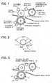
    Claims (11)

    1. A belt fixing unit for use in an image forming apparatus, comprising:
      a fixing roller;
      a heating roller;
      a fixing belt; and
      a pressing roller disposed in contact with said fixing roller to form a fixing nip having said fixing belt intervening in-between;
         wherein said fixing belt includes at least a base member formed of heat-resisting resin having a thickness of 90 µm or smaller, and wherein said fixing belt is exerted by a tensile force of 0.49 N/mm or less.
    2. The belt fixing unit according to claim 1, wherein
         said fixing belt is spanned around said fixing roller for forming said fixing nip, said heating roller housing therein a heat source, and at least one of other belt supporting members, and
      wherein said heating roller has a diameter equal to, or larger than that of one of said fixing roller and said at least one of other belt supporting members.
    3. An image forming apparatus comprising a belt fixing unit recited in claims 1 and 2, further comprising:
      a developing unit for developing a latent image into a toner image using a toner;
         wherein said toner is a low-melting point toner formed by subjecting a toner preparatory solution to at least one of extension reaction and crosslinking reaction in an aqueous medium, said toner preparatory solution containing at least a prepolymer having a functional group containing a nitrogen atom, polyester, colorant and releasing agent, dispersed in an organic solvent.
    4. The image forming apparatus according to claim 3, wherein
         said toner has a volume-average particle diameter Dv in a range from 3 to 8 µm and a ratio Dv/Dn in a range from 1.00 to 1.40, where Dn is a number-average particle diameter.
    5. The image forming apparatus according to claim 3, wherein
         a shape factor SF-1 of said toner is in a range from 100 to 180 and a further shape factor SF-2 in a range from 100 to 180, where SF-1 = {(MXLNG)2/ AREA} × 100π/4, and SF-2 = {(PERI)2/ AREA} × 100π/4, with MXLNG, AREA, and PERI being a maximum length, a area, and a length of periphery, of an image of said toner in two-dimensional projection, respectively.
    6. The image forming apparatus according to claim 3, wherein
         said toner is approximately spherical in shape.
    7. The image forming apparatus according to claim 3, wherein
         a shape of said toner is approximated by an ellipsoid having a major axis with a length r1, a minor axis with a length r2 and a thickness r3 (r1 ≥ r2 ≥ r3),
         and wherein said toner has a ratio r2/r1 ranging from 0.5 to 1.0, and a ratio r3/ r2 ranging from 0.7 to 1.0.
    8. A toner for developing an electrostatic image in an image forming apparatus recited in claim 3,
         wherein
         said toner has a volume-average particle diameter Dv in a range from 3 to 8 µm and a ratio Dv/Dn in a range from 1.00 to 1.40, where Dn is a number-average particle diameter.
    9. The toner according to claim 8, wherein
         a shape factor SF-1 of said toner is in a range from 100 to 180 and a further shape factor SF-2 in a range from 100 to 180, where SF-1 = {(MXLNG)2/ AREA} × 100π/4, and SF-2 = {(PERI)2/ AREA} × 100π/4, with MXLNG, AREA, and PERI being a maximum length, a area, and a length of periphery, of an image of said toner in two-dimensional projection, respectively.
    10. The toner according to claim 8, wherein
         said toner is approximately spherical in shape.
    11. The toner according to claim 8, wherein
         a shape of said toner is approximated by an ellipsoid having a major axis with a length r1, a minor axis with a length r2 and a thickness r3 (r1≥ 2: r2 ≥ r3),
         and wherein said toner has a ratio r2/r1 ranging from 0.5 to 1.0 a ratio r3/ r2 ranging from 0.7 to 1.0.
    EP04029545A 2003-12-25 2004-12-14 Belt fixing unit wherein the fixing belt has a limited tensile force Withdrawn EP1550919A1 (en)

    Applications Claiming Priority (2)

    Application Number Priority Date Filing Date Title
    JP2003429895 2003-12-25
    JP2003429895A JP2005189461A (en) 2003-12-25 2003-12-25 Belt fixing device, image forming apparatus, and toner used in the image forming apparatus

    Publications (1)

    Publication Number Publication Date
    EP1550919A1 true EP1550919A1 (en) 2005-07-06

    Family

    ID=34567556

    Family Applications (1)

    Application Number Title Priority Date Filing Date
    EP04029545A Withdrawn EP1550919A1 (en) 2003-12-25 2004-12-14 Belt fixing unit wherein the fixing belt has a limited tensile force

    Country Status (5)

    Country Link
    US (2) US7127204B2 (en)
    EP (1) EP1550919A1 (en)
    JP (1) JP2005189461A (en)
    KR (1) KR20050065347A (en)
    CN (1) CN100388131C (en)

    Cited By (1)

    * Cited by examiner, † Cited by third party
    Publication number Priority date Publication date Assignee Title
    EP4036659A1 (en) * 2021-02-02 2022-08-03 Fujifilm Business Innovation Corp. Unit and image forming apparatus

    Families Citing this family (95)

    * Cited by examiner, † Cited by third party
    Publication number Priority date Publication date Assignee Title
    JP2006030249A (en) * 2004-07-12 2006-02-02 Ricoh Co Ltd Fixing apparatus and image forming apparatus
    US7925177B2 (en) 2004-07-21 2011-04-12 Ricoh Co, Ltd. Image fixing apparatus stably controlling a fixing temperature, and image forming apparatus using the same
    JP2006098901A (en) * 2004-09-30 2006-04-13 Konica Minolta Business Technologies Inc Image forming apparatus
    JP4264410B2 (en) * 2004-11-30 2009-05-20 株式会社リコー Fixing apparatus and image forming apparatus
    JP2006154487A (en) * 2004-11-30 2006-06-15 Ricoh Co Ltd Fixing apparatus, image forming apparatus, and fixing apparatus control method
    JP4883914B2 (en) * 2005-01-24 2012-02-22 株式会社リコー Fixing device and image forming apparatus using the same
    JP2006251488A (en) * 2005-03-11 2006-09-21 Ricoh Co Ltd Heat belt fixing device
    JP2006323294A (en) * 2005-05-20 2006-11-30 Ricoh Co Ltd Fixing device cleaning device and image forming apparatus having the same
    JP4689370B2 (en) * 2005-06-30 2011-05-25 株式会社リコー Fixing apparatus and image forming apparatus
    JP4798699B2 (en) * 2005-09-12 2011-10-19 株式会社リコー Image forming apparatus and fixing control method therefor
    JP2007079142A (en) 2005-09-14 2007-03-29 Ricoh Co Ltd Heating device, fixing device and image forming apparatus
    JP2007079184A (en) * 2005-09-15 2007-03-29 Ricoh Co Ltd Electrophotographic equipment
    JP4536628B2 (en) * 2005-09-16 2010-09-01 株式会社リコー Image forming apparatus, process cartridge, and image forming method
    JP2007206265A (en) 2006-01-31 2007-08-16 Ricoh Co Ltd Fixing apparatus and image forming apparatus
    JP4936430B2 (en) * 2006-05-29 2012-05-23 株式会社リコー Fixing apparatus and image forming apparatus
    JP4818826B2 (en) * 2006-06-19 2011-11-16 株式会社リコー Fixing apparatus and image forming apparatus
    JP5342739B2 (en) * 2006-08-03 2013-11-13 株式会社リコー Fixing apparatus and image forming apparatus
    JP4999444B2 (en) * 2006-12-20 2012-08-15 株式会社リコー Fixing apparatus and image forming apparatus
    JP5380774B2 (en) 2006-12-28 2014-01-08 日亜化学工業株式会社 Surface mount type side surface light emitting device and manufacturing method thereof
    JP5163931B2 (en) * 2007-03-08 2013-03-13 株式会社リコー Fixing apparatus and image forming apparatus
    US7925188B2 (en) 2007-03-15 2011-04-12 Ricoh Company Limited Development device, process cartridge, and image forming apparatus using the development device
    JP2008261953A (en) * 2007-04-10 2008-10-30 Ricoh Co Ltd Image forming apparatus
    US8428499B2 (en) * 2007-05-22 2013-04-23 Ricoh Company, Ltd. Image forming apparatus, and fixing apparatus having a heating member to heat a fixing member
    KR100861130B1 (en) * 2007-06-05 2008-09-30 삼성전자주식회사 Fixing apparatus and image forming apparatus having same
    US8244168B2 (en) * 2007-06-25 2012-08-14 Ricoh Company, Ltd. Image forming apparatus with movable transfer device
    US7595926B2 (en) * 2007-07-05 2009-09-29 Qualcomm Mems Technologies, Inc. Integrated IMODS and solar cells on a substrate
    JP4903641B2 (en) * 2007-07-10 2012-03-28 株式会社リコー Fixing device
    JP5036048B2 (en) * 2007-08-23 2012-09-26 株式会社リコー Fixing apparatus and image forming apparatus
    JP2009069397A (en) 2007-09-12 2009-04-02 Ricoh Co Ltd Fixing apparatus and image forming apparatus
    JP5015745B2 (en) * 2007-12-07 2012-08-29 株式会社リコー Fixing device and image forming apparatus
    EP2075645B1 (en) 2007-12-26 2014-11-05 Ricoh Company, Ltd. Image forming apparatus, and method of controlling warming-up time of image forming apparatus
    JP5552732B2 (en) * 2008-03-31 2014-07-16 株式会社リコー Fixing apparatus and image forming apparatus
    JP5424079B2 (en) * 2008-08-21 2014-02-26 株式会社リコー Fixing apparatus and image forming apparatus
    JP5177412B2 (en) * 2008-09-19 2013-04-03 株式会社リコー Image forming apparatus
    JP5387884B2 (en) * 2008-10-14 2014-01-15 株式会社リコー Fixing apparatus and image forming apparatus
    JP5233588B2 (en) * 2008-10-27 2013-07-10 株式会社リコー Fixing apparatus and image forming apparatus
    JP5095678B2 (en) * 2008-12-18 2012-12-12 株式会社リコー Image forming apparatus
    JP5405900B2 (en) * 2009-02-03 2014-02-05 シャープ株式会社 Fixing apparatus and image forming apparatus
    JP5201478B2 (en) * 2009-02-09 2013-06-05 株式会社リコー Fixing apparatus and image forming apparatus
    JP5339072B2 (en) * 2009-04-27 2013-11-13 株式会社リコー Fixing apparatus and image forming apparatus
    JP5304488B2 (en) * 2009-07-01 2013-10-02 カシオ電子工業株式会社 Belt-type fixing device and image forming apparatus having the same
    JP5186448B2 (en) * 2009-07-14 2013-04-17 京セラドキュメントソリューションズ株式会社 Fixing apparatus and image forming apparatus
    JP5464411B2 (en) * 2009-07-29 2014-04-09 株式会社リコー Fixing apparatus and image forming apparatus
    JP5521776B2 (en) * 2009-08-24 2014-06-18 株式会社リコー Fixing apparatus and image forming apparatus
    JP5321905B2 (en) * 2009-09-01 2013-10-23 株式会社リコー Fixing apparatus and image forming apparatus
    JP5549160B2 (en) * 2009-09-10 2014-07-16 株式会社リコー Fixing apparatus and image forming apparatus
    JP5366005B2 (en) 2009-09-10 2013-12-11 株式会社リコー Fixing apparatus and image forming apparatus
    JP5299690B2 (en) * 2009-09-10 2013-09-25 株式会社リコー Fixing apparatus and image forming apparatus
    JP2011064767A (en) * 2009-09-15 2011-03-31 Ricoh Co Ltd Fixing device and image forming apparatus
    JP2011064726A (en) 2009-09-15 2011-03-31 Ricoh Co Ltd Fixing device and image forming apparatus
    JP5326958B2 (en) 2009-09-15 2013-10-30 株式会社リコー Fixing apparatus and image forming apparatus
    JP5532977B2 (en) 2009-11-30 2014-06-25 株式会社リコー Fixing apparatus and image forming apparatus
    JP5403264B2 (en) * 2010-01-13 2014-01-29 株式会社リコー Fixing apparatus and image forming apparatus
    JP5381746B2 (en) 2010-01-26 2014-01-08 株式会社リコー Fixing apparatus and image forming apparatus
    US8600276B2 (en) * 2010-01-27 2013-12-03 Ricoh Company, Limited Heat conduction unit, fixing device, and image forming apparatus
    JP5445188B2 (en) * 2010-02-07 2014-03-19 株式会社リコー Fixing apparatus and image forming apparatus
    JP5445189B2 (en) 2010-02-08 2014-03-19 株式会社リコー Fixing apparatus and image forming apparatus
    JP5564981B2 (en) 2010-02-25 2014-08-06 株式会社リコー Fixing apparatus and image forming apparatus
    JP5418913B2 (en) * 2010-03-04 2014-02-19 株式会社リコー Fixing apparatus and image forming apparatus
    JP5600970B2 (en) 2010-03-08 2014-10-08 株式会社リコー Fixing apparatus and image forming apparatus
    JP5440278B2 (en) 2010-03-10 2014-03-12 株式会社リコー Fixing apparatus and image forming apparatus
    JP5633386B2 (en) 2010-03-10 2014-12-03 株式会社リコー Fixing apparatus and image forming apparatus
    JP5408553B2 (en) 2010-03-12 2014-02-05 株式会社リコー Fixing apparatus and image forming apparatus
    JP5625406B2 (en) * 2010-03-16 2014-11-19 株式会社リコー Image forming apparatus
    JP5589526B2 (en) * 2010-03-18 2014-09-17 株式会社リコー Fixing apparatus and image forming apparatus
    JP2011197183A (en) * 2010-03-18 2011-10-06 Ricoh Co Ltd Fixing device and image forming apparatus
    JP2011209409A (en) * 2010-03-29 2011-10-20 Sharp Corp Fixing device and image forming apparatus including the same
    JP2012108461A (en) 2010-05-28 2012-06-07 Ricoh Co Ltd Fixing device and image forming apparatus using the same
    US8666270B2 (en) 2010-06-21 2014-03-04 Ricoh Company, Ltd. Image forming apparatus
    JP5499999B2 (en) 2010-08-31 2014-05-21 株式会社リコー Image forming apparatus
    JP5640684B2 (en) * 2010-11-12 2014-12-17 富士ゼロックス株式会社 Electrostatic photographic developer, process cartridge, image forming apparatus and image forming method
    JP5625865B2 (en) 2010-12-16 2014-11-19 株式会社リコー Fixing apparatus and image forming apparatus
    JP5589820B2 (en) 2010-12-17 2014-09-17 株式会社リコー Fixing apparatus and image forming apparatus
    JP5640750B2 (en) 2011-01-07 2014-12-17 株式会社リコー Fixing apparatus, image forming apparatus, and fixing control method
    JP5825545B2 (en) 2011-01-11 2015-12-02 株式会社リコー Fixing apparatus and image forming apparatus
    JP5730595B2 (en) * 2011-01-28 2015-06-10 株式会社沖データ Fixing apparatus and image forming apparatus having the same
    JP2012185295A (en) 2011-03-04 2012-09-27 Ricoh Co Ltd Fixing device and image forming apparatus
    JP5768507B2 (en) 2011-03-17 2015-08-26 株式会社リコー Fixing apparatus and image forming apparatus
    JP5773151B2 (en) 2011-08-17 2015-09-02 株式会社リコー Fixing apparatus and image forming apparatus
    JP2013083730A (en) * 2011-10-06 2013-05-09 Sharp Corp Fixing device, and image forming apparatus
    JP5737629B2 (en) 2011-12-26 2015-06-17 株式会社リコー Fixing apparatus and image forming apparatus
    JP5928783B2 (en) 2012-01-11 2016-06-01 株式会社リコー Fixing apparatus and image forming apparatus
    JP5761524B2 (en) 2012-01-13 2015-08-12 株式会社リコー Fixing apparatus and image forming apparatus
    JP5737520B2 (en) 2012-01-13 2015-06-17 株式会社リコー Fixing apparatus and image forming apparatus
    JP6333511B6 (en) 2012-01-23 2023-11-08 株式会社リコー Fixing device and image forming device
    JP6052598B2 (en) 2012-01-30 2016-12-27 株式会社リコー Fixing apparatus and image forming apparatus
    JP2013164463A (en) 2012-02-09 2013-08-22 Ricoh Co Ltd Fixation device and image formation apparatus
    JP6209311B2 (en) 2012-02-09 2017-10-04 株式会社リコー Fixing apparatus and image forming apparatus
    JP6103679B2 (en) 2012-02-09 2017-03-29 株式会社リコー Fixing apparatus and image forming apparatus
    JP2013195857A (en) 2012-03-22 2013-09-30 Ricoh Co Ltd Fixing device, and image forming apparatus
    JP5950152B2 (en) 2012-03-22 2016-07-13 株式会社リコー Fixing apparatus and image forming apparatus
    JP2016142898A (en) * 2015-02-02 2016-08-08 コニカミノルタ株式会社 Fixing belt, fixing device, image forming apparatus, and image forming method
    JP6661894B2 (en) * 2015-06-08 2020-03-11 コニカミノルタ株式会社 Fixing device and image forming device
    JP6550957B2 (en) * 2015-06-22 2019-07-31 コニカミノルタ株式会社 Fixing device and image forming apparatus
    CN109752935B (en) * 2018-12-26 2021-08-03 平田精密器材(深圳)有限公司 Conductive roller with stable resistance value and preparation method thereof

    Citations (4)

    * Cited by examiner, † Cited by third party
    Publication number Priority date Publication date Assignee Title
    JPH0844228A (en) * 1994-08-03 1996-02-16 Tomoegawa Paper Co Ltd Electrophotographic toner fixing method
    JPH1048869A (en) * 1996-07-31 1998-02-20 Canon Inc Toner and image forming method
    EP0930548A1 (en) * 1996-10-04 1999-07-21 Ricoh Company, Ltd. Belt type fixing device
    JP2002207309A (en) * 2001-01-10 2002-07-26 Canon Inc Image forming method

    Family Cites Families (18)

    * Cited by examiner, † Cited by third party
    Publication number Priority date Publication date Assignee Title
    JP3248025B2 (en) 1993-04-21 2002-01-21 キヤノン株式会社 Toner for developing electrostatic images
    JP3711764B2 (en) * 1997-10-29 2005-11-02 コニカミノルタビジネステクノロジーズ株式会社 Fixing device and image forming apparatus using the fixing device
    JP3762079B2 (en) 1997-11-17 2006-03-29 三洋化成工業株式会社 Dry toner and its production method
    ATE275392T1 (en) * 1999-04-12 2004-09-15 Shionogi & Co METHOD FOR PRODUCING MEDICINAL PRODUCTS OF A BASIC HYDROPHOBIC ACTIVE SUBSTANCE
    JP4106170B2 (en) * 1999-04-22 2008-06-25 シンジーテック株式会社 Oil application roller used in image forming apparatus
    JP4077985B2 (en) * 1999-07-01 2008-04-23 キヤノン株式会社 Toner and image forming method
    JP2002108094A (en) 2000-09-29 2002-04-10 Canon Inc Developing device
    JPWO2002056116A1 (en) * 2001-01-05 2004-05-20 株式会社リコー Electrophotographic toner
    JP4659233B2 (en) * 2001-02-27 2011-03-30 キヤノン株式会社 Developer regulating member, developing device, process cartridge, and image forming apparatus
    JP2003084609A (en) 2001-06-04 2003-03-19 Ricoh Co Ltd Fixing device and image forming device
    JP2003029484A (en) 2001-07-11 2003-01-29 Konica Corp Image forming method
    JP2003091100A (en) * 2001-09-19 2003-03-28 Ricoh Co Ltd Dry toner and image forming apparatus using the toner
    JP3640918B2 (en) 2001-11-02 2005-04-20 株式会社リコー Toner for electrostatic image development and production method
    JP3844201B2 (en) 2001-11-20 2006-11-08 株式会社リコー Fixing device and image forming apparatus having the same
    JP2003241555A (en) 2002-02-14 2003-08-29 Ricoh Co Ltd Fixing device and image forming device
    JP3975794B2 (en) 2002-03-20 2007-09-12 富士ゼロックス株式会社 Fixing device
    CN1315013C (en) * 2002-09-24 2007-05-09 株式会社理光 Cleaner, topping case, imager and toner
    JP2007121653A (en) * 2005-01-26 2007-05-17 Ricoh Co Ltd Fixing method, fixing device, image forming method, and image forming apparatus

    Patent Citations (4)

    * Cited by examiner, † Cited by third party
    Publication number Priority date Publication date Assignee Title
    JPH0844228A (en) * 1994-08-03 1996-02-16 Tomoegawa Paper Co Ltd Electrophotographic toner fixing method
    JPH1048869A (en) * 1996-07-31 1998-02-20 Canon Inc Toner and image forming method
    EP0930548A1 (en) * 1996-10-04 1999-07-21 Ricoh Company, Ltd. Belt type fixing device
    JP2002207309A (en) * 2001-01-10 2002-07-26 Canon Inc Image forming method

    Non-Patent Citations (3)

    * Cited by examiner, † Cited by third party
    Title
    PATENT ABSTRACTS OF JAPAN vol. 1996, no. 06 28 June 1996 (1996-06-28) *
    PATENT ABSTRACTS OF JAPAN vol. 1998, no. 06 30 April 1998 (1998-04-30) *
    PATENT ABSTRACTS OF JAPAN vol. 2002, no. 11 6 November 2002 (2002-11-06) *

    Cited By (2)

    * Cited by examiner, † Cited by third party
    Publication number Priority date Publication date Assignee Title
    EP4036659A1 (en) * 2021-02-02 2022-08-03 Fujifilm Business Innovation Corp. Unit and image forming apparatus
    US11543758B2 (en) 2021-02-02 2023-01-03 Fujifilm Business Innovation Corp. Unit and image forming apparatus for fixing a toner image with a developer including a brilliant toner containing a flat brilliant pigment

    Also Published As

    Publication number Publication date
    US7313353B2 (en) 2007-12-25
    US7127204B2 (en) 2006-10-24
    CN1645271A (en) 2005-07-27
    JP2005189461A (en) 2005-07-14
    US20050163543A1 (en) 2005-07-28
    CN100388131C (en) 2008-05-14
    KR20050065347A (en) 2005-06-29
    US20070014603A1 (en) 2007-01-18

    Similar Documents

    Publication Publication Date Title
    US7127204B2 (en) Belt fixing unit with heat-resisting resin base member and image forming toner for use in the fixing unit
    US7400844B2 (en) Image forming apparatus and process cartridge with a cleaner for removing toner from an image bearing member
    US7056638B1 (en) Toner for electrophotography, developer using the same, process cartridge using the same, image-forming apparatus using the same, and image-forming process using the same
    EP1477867B1 (en) Cleaner, and process cartridge and image forming apparatus including the cleaner
    US7266324B2 (en) Charging device, and process cartridge and image forming apparatus using the charging device
    CN100474154C (en) Charging device, and process cartridge and image forming apparatus using the charging device
    US9454126B2 (en) Cleaning device and image forming apparatus including same
    US7953362B2 (en) Image forming apparatus, process cartridge, and lubricant applicator
    US7343132B2 (en) Image forming apparatus and process cartridge including sealable lubricating device
    EP2492754B1 (en) Image forming apparatus and method, and toner, developer and process cartridge for forming image
    US20060115286A1 (en) Electrophotographic image forming apparatus, and toner, process cartridge and image forming method therefor
    JP2006258901A (en) Non-magnetic one-component electrostatic charge developing toner and image forming method using the same
    JP2009086616A (en) Image forming apparatus
    JP2005128380A (en) Fixing apparatus, image forming apparatus, and toner used therefor
    JP2007065018A (en) Lubricant coating apparatus and image forming apparatus
    JP7508837B2 (en) Image forming apparatus and image forming method
    JP2004184704A (en) Image forming method
    JP2005031121A (en) Image forming apparatus, toner
    JP2009020212A (en) Image forming apparatus
    JP2009109670A (en) Image forming apparatus
    JP2004184853A (en) Image forming method and apparatus
    JP2007333940A (en) Image forming apparatus
    JP2008170623A (en) Image forming apparatus

    Legal Events

    Date Code Title Description
    PUAI Public reference made under article 153(3) epc to a published international application that has entered the european phase

    Free format text: ORIGINAL CODE: 0009012

    AK Designated contracting states

    Kind code of ref document: A1

    Designated state(s): AT BE BG CH CY CZ DE DK EE ES FI FR GB GR HU IE IS IT LI LT LU MC NL PL PT RO SE SI SK TR

    AX Request for extension of the european patent

    Extension state: AL BA HR LV MK YU

    17P Request for examination filed

    Effective date: 20051118

    AKX Designation fees paid

    Designated state(s): DE ES FR GB IT NL

    17Q First examination report despatched

    Effective date: 20120530

    STAA Information on the status of an ep patent application or granted ep patent

    Free format text: STATUS: THE APPLICATION IS DEEMED TO BE WITHDRAWN

    18D Application deemed to be withdrawn

    Effective date: 20121010