EP1550844A1 - Dispositif de détection de rotation d'un élément tournant tel que la turbine d'un compteur d'eau - Google Patents
Dispositif de détection de rotation d'un élément tournant tel que la turbine d'un compteur d'eau Download PDFInfo
- Publication number
- EP1550844A1 EP1550844A1 EP04300958A EP04300958A EP1550844A1 EP 1550844 A1 EP1550844 A1 EP 1550844A1 EP 04300958 A EP04300958 A EP 04300958A EP 04300958 A EP04300958 A EP 04300958A EP 1550844 A1 EP1550844 A1 EP 1550844A1
- Authority
- EP
- European Patent Office
- Prior art keywords
- detector
- mark
- amplitude
- detectors
- threshold value
- Prior art date
- Legal status (The legal status is an assumption and is not a legal conclusion. Google has not performed a legal analysis and makes no representation as to the accuracy of the status listed.)
- Granted
Links
- XLYOFNOQVPJJNP-UHFFFAOYSA-N water Substances O XLYOFNOQVPJJNP-UHFFFAOYSA-N 0.000 title claims description 12
- 230000033001 locomotion Effects 0.000 title claims description 7
- 230000005284 excitation Effects 0.000 claims abstract description 54
- 230000001419 dependent effect Effects 0.000 claims description 4
- 230000003247 decreasing effect Effects 0.000 claims description 2
- 239000007769 metal material Substances 0.000 claims description 2
- 230000003534 oscillatory effect Effects 0.000 claims 1
- 230000007704 transition Effects 0.000 claims 1
- 238000001514 detection method Methods 0.000 description 15
- 238000000034 method Methods 0.000 description 4
- 238000004364 calculation method Methods 0.000 description 3
- 239000012530 fluid Substances 0.000 description 3
- 230000001427 coherent effect Effects 0.000 description 2
- 230000001939 inductive effect Effects 0.000 description 2
- 239000000463 material Substances 0.000 description 2
- 230000003044 adaptive effect Effects 0.000 description 1
- 230000032683 aging Effects 0.000 description 1
- 238000004458 analytical method Methods 0.000 description 1
- 230000005540 biological transmission Effects 0.000 description 1
- 239000003990 capacitor Substances 0.000 description 1
- 238000005265 energy consumption Methods 0.000 description 1
- 235000021183 entrée Nutrition 0.000 description 1
- 238000004519 manufacturing process Methods 0.000 description 1
- 238000005259 measurement Methods 0.000 description 1
- 239000003607 modifier Substances 0.000 description 1
- 239000002991 molded plastic Substances 0.000 description 1
- 229910052755 nonmetal Inorganic materials 0.000 description 1
Images


Classifications
-
- G—PHYSICS
- G01—MEASURING; TESTING
- G01F—MEASURING VOLUME, VOLUME FLOW, MASS FLOW OR LIQUID LEVEL; METERING BY VOLUME
- G01F15/00—Details of, or accessories for, apparatus of groups G01F1/00 - G01F13/00 insofar as such details or appliances are not adapted to particular types of such apparatus
- G01F15/06—Indicating or recording devices
Definitions
- the invention relates to a device for detecting rotation of a rotating element such as the turbine of a water meter.
- Most water meters include a totalizer mechanical drive, that is to say that the rotation of the turbine drives, through a mechanical and / or magnetic transmission, the rollers of the counter index.
- FIG. 1 illustrates such detection mode.
- the rotating assembly is constituted by a turbine 1 of a flow meter not shown and a disc 2 secured to the turbine 1.
- turbine 1 and disk 2 are animated with a rotational movement about the axis XX '.
- the speed of rotation of the rotating element is directly connected to the instantaneous flow of the fluid.
- Two proximity sensors L0 and L1 located in a plane P perpendicular to the axis XX ', in two radial directions with respect to the axis XX 'are sensitive to the proximity of a mark 5 which is secured to the disk 2 and eccentric with respect to the axis of rotation XX '. It follows that when the rotating element is animated by a rotational movement, the response of proximity switches L0 and L1 will evolve depending on the position of the As an illustration, the two proximity switches L0 and L1 are example of magnetic coils coupled in parallel with capacitors forming two oscillating circuits arranged in two opposite radial directions.
- the disc 2 is made of non-metallic material such only molded plastic and the mark 5 is a metallized radial sector of the disk.
- Such a detection system poses certain difficulties; in Indeed, there is a series of parameters that varies with time.
- this is the water temperature that can vary the characteristics of the detector, the supply voltage of the detection circuit, especially when the power supply is via a battery, and the variable distance between the proximity switch and the rotating element due to the lifting of the high speed turbine.
- the rotation detection device described in this document includes at least two proximity sensors intended to detect the passage of a mark integral with the rotating element.
- the device performs an analysis of the evolution of the signal delivered by a first detector. As soon as the mark has been detected at the detector, increment the index of the number of turns and select the second detector, thereby excluding the first detector that has just detected the Mark ; parameters intended to study the evolution of the signals of the second detector are then reset and a system is thus obtained. adaptive to overcome the problems associated with the variation of settings.
- the device of this solution uses an electronic circuit complex therefore not only a treatment time relatively long but also a high energy consumption.
- the reinitialization of the parameters used to identify the passage of a mark at the detector level is based on a search for these parameters by successive approximations from a binary detection information, ie a value of comparison with a threshold value.
- the device of the invention provides a simplified system based on the interpretation of binary and non-binary information on the direct measurement of the parameters. This technique of binary logic by successive approximations saves time and is more adapted to a low consumption environment, logic circuits used being relatively simple and low energy consumers.
- said rotating element is in a non metal and said mark is formed by a metallized portion of said rotating element.
- each proximity detector is a circuit oscillator and said excitation circuit comprises a pulse generator successively feeding each detector so that the answer of excitation of each of the detectors is a more or less oscillating signal damped according to whether or not the mark is at the level of said detector, said signal presenting a succession of positive and negative lobes of amplitude decreasing, each lobe can be successively numbered.
- the duration of said observation window substantially corresponds to the duration of a given lobe of said response excitation.
- the frequency of said pulse generator is between 50 and 500 Hz and the excitation response of each of the detectors has a frequency approximately equal to 250 kHz.
- said observation window may vary according to the lobe chosen so that said comparison means are adapted to make a comparison on an observation window that shifts temporally according to the chosen lobe number.
- said rotating element comprises a disk integral with the turbine of a water meter, said water meter being integrated in a calorimeter intended to account for the energy delivered by a hot water circuit.
- said comparison threshold value is a value Of voltage.
- said reset means operate in the absence of rotation of said rotating element.
- FIG. 2 represents a device 10 for detecting the rotation of a rotating element according to a first embodiment of the invention.
- the device 10 can for example be used with the detection system of the FIG. 1 and makes it possible to detect the rotation of the disk 2 integral with the turbine 1.
- the disc is equipped of an off-axis mark with respect to the axis XX 'and capable of modifying the amplitude response of proximity sensors when the disk is animated by a rotation movement.
- the excitation circuit 11 makes it possible to excite the two detectors L0 and L1 at the same time and output a voltage Vc corresponding to the excitation response of one of the detectors L0 or L1.
- the switch 20 makes it possible to provide on the positive input of the comparator 12 the excitation response of one of the two detectors L0 or L1.
- this voltage Vc is compared with a reference voltage Vseuil_detect provided by a generator 22.
- This reference voltage Vseuil_detect fixed is injected on the negative input of the Comparator 12.
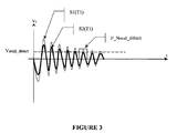
- Figure 3 illustrates this mode of operation in having two excitation responses S1 (T1) and S2 (T1) as a function of time. These two excitations are obtained at a first temperature T1.
- the response S1 (T1) is a weakly damped signal indicating that the mark is not under the detector being analyzed.
- this signal S1 (T1) (just like the signal S2 (T1)) is a oscillating signal comprising a plurality of positive and negative lobes; subsequently, we will number the positive lobes from one to one.
- the comparator 12 gives on its output a logical level X equal to 1 indicating that the mark is not under the detector analyzed.
- the comparator 12 gives on its output a logical level X equal to 0 indicating that the mark is under the detector analyzed. So the means 14 to identify the passage of the mark to the level of the detectors will memorize this state 0 in a device of memorizing 17 and count a half-turn in a device of counting 18. (1 / m turn in the case of m detectors with m higher or equal to two).
- the signal S1 (T2) is always in below the signal S1 (T1); by making a comparison on the window of observation F_Nseuil_detect previously defined, the amplitude of the signal S1 (T2) is already under the threshold Vseuil_mütect while we know that the mark is not under the detector. Therefore, it is important to be able to reset F_Nseuil_detect in order to obtain a coherent result. For that, the second switch 19 is switched to its second position 191.
- the control means 23 can shift the window to the left following the dashed arrow (decrementing from one to one the lobe number) until obtaining a window F_Nmax (corresponding to the lobe placed at the Nmax position) for which the amplitude of the signal S1 (T2) goes back above the voltage Vseuil_detect.
- This window F_Nmax is determined by observation window search device 15 informed by the passage of X from 0 to 1.
- the computing device of 16 uses these values to calculate a lobe number Nseuil_converget reset and defined by the relationship :
- Nseuil_detect Nmax - Ns, where Ns is a known and clean fixed integer to each proximity detector. It is also possible to take a Ns value common to each of the detectors.
- Nseuil_detect defines a new window of observation F_Nseuil_mütect for which one is certain that the device 10 will not detect the presence of the mark when it is not under the detector to be analyzed.
- the computing device of 16 transmits this new value of F_Nseuil_detect the control means 21 who will use this new value during subsequent detections.
- the reset principle will be the same if the signal amplitude of the detector analyzed increases (case of a decrease in temperature); in this case, it will be necessary to look for the new maximum positive lobe for the amplitude of the signal is above the comparison voltage Vseuil_detect fixed.
- means included in the means of reset 13 may for example be achieved using means software by programming a microprocessor.
- the calibration of the detectors can be done either every 1 / m of turn in the case of m detectors, that is to say at each detection of the brand but it can also be done at a more relaxed time in depending on the variation of the influence parameters, the latter being able to vary relatively slowly.
- FIG. 6 represents a device 100 for detecting the rotation of a rotating element according to a second embodiment of the invention.
- the device 100 can for example be used with the detection system of FIG. 1 and makes it possible to detect the rotation of the disc 2 integral with the turbine 1.
- the disc is equipped of an off-axis mark with respect to the axis XX 'and capable of modifying the amplitude response of proximity sensors when the disk is animated by a rotation movement.
- the excitation circuit 101 makes it possible to excite the two detectors L0 and L1 at the same time and output a voltage Vc corresponding to the excitation response of one of the detectors L0 or L1.
- the switch 120 provides on the positive input of the comparator 102 the excitation response of one of the two detectors L0 or L1.
- this voltage Vc is compared with a reference voltage Vseuil_detect provided by a generator 122.
- This reference voltage Vseuil_detect is injected on the negative input of the comparator 102.
- Figure 7 illustrates this mode of operation in having two excitation responses S'1 (T1) and S'2 (T1) as a function of time. These two excitations are obtained at a first temperature T1.
- the response S'1 (T1) is a weakly damped signal indicating that the mark is not under the detector being analyzed.
- this signal S'1 (T1) (just like the signal S'2 (T1)) is a oscillating signal comprising a plurality of positive and negative lobes; subsequently, we will number the positive lobes from one to one.
- the comparator 102 gives on its output a logical level X equal to 1 indicating that the mark is not under the detector analyzed.
- the comparator 102 gives on its output a logical level X equal to 0 indicating that the mark is under the detector analyzed. So the means 104 to identify the passage of the mark to the level of the detectors will memorize this state 0 in a device of memorizing 107 and count a half-turn in a device of counting 108. (1 / m turn in the case of m detectors with m higher or equal to two).
- the second switch 119 has two positions 119a and 119b.
- the normal operating position (excluding reset) is the position 119a for which the negative input of the comparator 102 is connected to Vseuil_detect provided by the generator 122.
- the switch 119 is switched on its second position 119b so that means 123 can inject a variable voltage Vvar on the negative input of the comparator 102 and therefore to decrease the voltage Vseuil_détect initially on the negative input up to a voltage Vmax for which the amplitude of the signal S'1 (T2) goes back above the voltage Vmax.
- This voltage Vmax is determined by the voltage search device 105 informed by the passage of X from 0 to 1.
- Vvar is decremented until a logical 1 is obtained.
- the computing device 106 transmits this new value of Vseuil_detect at generator 122 which will use this new value during following detections.
- the device 100 will not detect the presence of the mark when this is not under the detector to be analyzed.
- the F_Nseuil_detect window also corresponds to the duration of supply of the means 123. Such a power supply enables reduce consumption.
- the reset is done by successive approximation by varying the value of a parameter and interpreting the binary information of the logic level X.
- the means of calculation have been described as means software programmed on a microprocessor but they can also be made using material means.
Landscapes
- Physics & Mathematics (AREA)
- Fluid Mechanics (AREA)
- General Physics & Mathematics (AREA)
- Measuring Volume Flow (AREA)
- Transmission And Conversion Of Sensor Element Output (AREA)
- Investigating Or Analyzing Materials By The Use Of Electric Means (AREA)
- Control Of Eletrric Generators (AREA)
Abstract
Description
- m détecteurs de proximité situés dans un plan perpendiculaire à l'axe XX' selon m directions radiales, m étant un entier supérieur ou égal à 2, une marque étant solidaire dudit élément tournant et excentrée par rapport à l'axe XX' et étant susceptible de modifier la réponse en amplitude desdits détecteurs de proximité lorsque ledit élément tournant est animé d'un mouvement de rotation,
- un circuit d'excitation destiné à exciter lesdits détecteurs de proximité, chacun desdits détecteurs fournissant une réponse d'excitation lorsqu'il est excité,
- des moyens de comparaison de l'amplitude de la réponse d'excitation de chacun des détecteurs avec une valeur seuil de comparaison, pendant une période temporelle, dite fenêtre d'observation, et pour fournir un niveau logique 1 ou 0 selon que l'amplitude de réponse est supérieure ou inférieure à ladite valeur seuil de comparaison,
- des moyens pour identifier le passage de ladite marque au niveau d'un desdits détecteurs en fonction de la valeur 0 ou 1 dudit niveau logique,
- des moyens de réinitialisation de ladite valeur seuil de comparaison ou de ladite fenêtre d'observation caractéristiques d'un détecteur, ladite réinitialisation se produisant par itérations successives en utilisant la valeur 0 ou 1 dudit niveau logique lorsque ladite marque ne peut pas être au niveau dudit détecteur.
- des moyens de détermination par itérations successives, sur une fenêtre d'observation prédéterminée, de l'amplitude de la réponse d'excitation d'un détecteur lorsque ladite marque ne peut pas être au niveau dudit détecteur, en utilisant le passage d'un état logique à l'autre dudit niveau logique issu de la comparaison de ladite amplitude de la réponse d'excitation avec ladite valeur seuil de comparaison variable,
- des moyens pour fixer ladite valeur seuil de comparaison à une valeur dépendant de ladite amplitude de la réponse d'excitation déterminée par lesdits moyens de détermination.
- des moyens de détermination par itérations successives, pour une valeur seuil de comparaison fixée, du numéro de lobe de la réponse d'excitation d'un détecteur lorsque ladite marque ne peut pas être au niveau dudit détecteur, en utilisant le passage d'un état logique à l'autre dudit niveau logique issu de la comparaison de ladite amplitude de la réponse d'excitation avec ladite valeur seuil de comparaison fixée lorsque le numéro de lobe varie,
- des moyens pour calibrer ladite fenêtre d'observation à une valeur dépendant dudit numéro de lobe déterminé par lesdits moyens de détermination.
- au moins trois détecteurs de proximité,
- des moyens pour déterminer le sens de rotation dudit élément tournant.
- La figure 1 représente un système de détection selon l'état de la technique,
- La figure 2 représente un dispositif de détection selon un premier mode de réalisation de l'invention,
- Les figures 3 à 5 représentent des signaux obtenus avec un détecteur de proximité utilisé dans le dispositif de détection de la figure 2,
- La figure 6 représente un dispositif de détection selon un deuxième mode de réalisation de l'invention,
- Les figures 7 à 9 représentent des signaux obtenus avec un détecteur de proximité utilisé dans le dispositif de détection de la figure 6,
- Les figures 10 et 11 représentent trois détecteurs utilisés dans un des dispositifs représentés sur l'une des figures 2 ou 6.
- deux détecteurs de proximité L1 et L0 semblables aux détecteurs de la figure 1,
- un circuit d'excitation 11,
- un premier commutateur 20,
- un comparateur 12,
- des moyens 14 pour identifier le passage de la marque au niveau des détecteurs L1 ou L0,
- des moyens de réinitialisation 13.
- le deuxième commutateur 19 déjà défini,
- des moyens de commande 23 permettant d'injecter une fenêtre d'observation variable sur le comparateur 12,
- un dispositif de recherche de fenêtre d'observation 15,
- un dispositif de calcul de F_Nseuil_détect 16.
- deux détecteurs de proximité L1 et L0 semblables aux détecteurs de la figure 1,
- un circuit d'excitation 101,
- un premier commutateur 120,
- un comparateur 102,
- des moyens 104 pour identifier le passage de la marque au niveau des détecteurs L1 ou L0,
- des moyens de réinitialisation 103.
- un deuxième commutateur 119,
- des moyens 123 permettant d'injecter une tension variable Vvar sur l'entrée négative du comparateur 102,
- un dispositif de recherche de tension 105,
- un dispositif de calcul de Vseuil_détect 106.
Claims (13)
- Dispositif (10, 100) pour détecter la rotation d'un élément tournant autour d'un axe XX' comprenant :ledit dispositif (10, 100) étant caractérisé en ce qu'il comporte :m détecteurs (L0, L1) de proximité situés dans un plan perpendiculaire à l'axe XX' selon m directions radiales, m étant un entier supérieur ou égal à 2, une marque étant solidaire dudit élément tournant et excentrée par rapport à l'axe XX' et étant susceptible de modifier la réponse en amplitude desdits détecteurs de proximité lorsque ledit élément tournant est animé d'un mouvement de rotation,un circuit d'excitation (11, 101) destiné à exciter lesdits détecteurs de proximité, chacun desdits détecteurs fournissant une réponse d'excitation lorsqu'il est excité,des moyens de comparaison (12, 102) de l'amplitude de la réponse d'excitation de chacun des détecteurs (L0, L1) avec une valeur seuil de comparaison, pendant une période temporelle, dite fenêtre d'observation, et pour fournir un niveau logique 1 ou 0 selon que l'amplitude de réponse est supérieure ou inférieure à ladite valeur seuil de comparaison,des moyens (14, 104) pour identifier le passage de ladite marque au niveau d'un desdits détecteurs (L0, L1) en fonction de la valeur 0 ou 1 dudit niveau logique,des moyens de réinitialisation (13, 103) de ladite valeur seuil de comparaison ou de ladite fenêtre d'observation caractéristiques d'un détecteur (L0, L1), ladite réinitialisation se produisant par itérations successives en utilisant la valeur 0 ou 1 dudit niveau logique lorsque ladite marque ne peut pas être au niveau dudit détecteur (L0, L1).
- Dispositif (10, 100) selon la revendication 1 caractérisé en ce que ledit élément tournant est en matière non métallique et ladite marque est formée par une partie métallisée dudit élément tournant.
- Dispositif (10, 100) selon la revendication 1 ou 2 caractérisé en ce que chaque détecteur de proximité est un circuit oscillant et ledit circuit d'excitation comprend un générateur d'impulsion ali mentant successivement chaque détecteur de sorte que la réponse d'excitation de chacun des détecteurs est un signal oscillant plus ou moins amorti selon que la marque est ou non au niveau dudit détecteur, ledit signal présentant une succession de lobes positifs et négatifs d'amplitude décroissante, chaque lobe pouvant successivement être numéroté.
- Dispositif (10, 100) selon la revendication 3 caractérisé en ce que la durée de ladite fenêtre d'observation correspond sensiblement à la durée d'un lobe déterminé de ladite réponse d'excitation.
- Dispositif (10, 100) selon l'une des revendications 3 ou 4 caractérisé en ce que la fréquence dudit générateur d'impulsion se situe entre 50 et 500 Hz.
- Dispositif (10, 100) selon l'une des revendications 3 à 5 caractérisé en ce que la réponse d'excitation de chacun des détecteurs a une fréquence environ égale à 250 kHz.
- Dispositif (100) selon l'une des revendications 1 à 6 caractérisé en ce que lesdits moyens de comparaison (102) sont adaptés pour recevoir une valeur seuil de comparaison variable (Vvar) de sorte que l'amplitude de la réponse d'excitation de chacun des détecteurs (L0, L1) peut être comparée avec ladite valeur seuil de comparaison variable (Vvar), lesdits moyens de réinitialisation (103) comportant :des moye ns de détermination (105) par itérations successives, sur une fenêtre d'observation prédéterminée, de l'amplitude de la réponse d'excitation d'un détecteur lorsque ladite marque ne peut pas être au niveau dudit détecteur, en utilisant le passage d'un état logique à l'autre dudit niveau logique issu de la comparaison de ladite amplitude de la réponse d'excitation avec ladite valeur seuil de comparaison variable,des moyens (106) pour calibrer ladite valeur seuil de comparaison à une valeur dépendant de ladite amplitude de la réponse d'excitation déterminée par lesdits moyens de détermination (105).
- Dispositif (10) selon l'une des revendications 4 à 6 caractérisé en ce que ladite fenêtre d'observation peut varier selon le lobe choisi de sorte que lesdits moyens de comparaison (12) sont adaptés pour effectuer une comparaison sur une fenêtre d'observation qui se décale temporellement en fonction du numéro de lobe choisi.
- Dispositif (10) selon la revendication 8 caractérisé en ce que lesdits moyens de réinitialisation comporte:des moyens de détermination (15) par itérations successives, pour une valeur seuil de comparaison fixée, du numéro de lobe de la réponse d'excitation d'un détecteur (L0, L1) lorsque ladite marque ne peut pas être au niveau dudit détecteur, en utilisant le passage d'un état logique à l'autre dudit niveau logique issu de la comparaison de ladite amplitude de la réponse d'excitation avec ladite valeur seuil de comparaison fixée lorsque le numéro de lobe varie,des moyens pour calibrer (16) ladite fenêtre d'observation à une valeur dépendant dudit numéro de lobe déterminé par lesdits moyens de détermination (15).
- Dispositif (10, 100) selon l'une des revendications précédentes caractérisé en ce que ledit élément tournant comprend un disque solidaire de la turbine d'un compteur d'eau, ledit compteur d'eau pouvant être intégré dans un calorimètre destiné à comptabiliser l'énergie délivrée par un circuit d'eau chaude.
- Dispositif (10, 100) selon l'une des revendications précédentes caractérisé en ce que ladite valeur seuil de comparaison est une valeur de tension.
- Dispositif selon l'une des revendications précédentes caractérisé en ce qu'il comporte :au moins trois détecteurs (L0, L1, L2) de proximité,des moyens pour déterminer le sens de rotation dudit élément tournant.
- Dispositif selon l'une des revendications précédentes caractérisé en ce que lesdits moyens de réinitialisation (13, 103) fonctionnent en l'absence de rotation dudit élément tournant.
Applications Claiming Priority (2)
| Application Number | Priority Date | Filing Date | Title |
|---|---|---|---|
| FR0351240 | 2003-12-31 | ||
| FR0351240A FR2864615B1 (fr) | 2003-12-31 | 2003-12-31 | Dispositif de detection d'un element tournant tel que la turbine d'un compteur d'eau |
Publications (2)
| Publication Number | Publication Date |
|---|---|
| EP1550844A1 true EP1550844A1 (fr) | 2005-07-06 |
| EP1550844B1 EP1550844B1 (fr) | 2012-02-29 |
Family
ID=34566401
Family Applications (1)
| Application Number | Title | Priority Date | Filing Date |
|---|---|---|---|
| EP04300958A Not-in-force EP1550844B1 (fr) | 2003-12-31 | 2004-12-31 | Dispositif de détection de rotation d'un élément tournant tel que la turbine d'un compteur d'eau |
Country Status (6)
| Country | Link |
|---|---|
| US (1) | US7106054B2 (fr) |
| EP (1) | EP1550844B1 (fr) |
| CN (1) | CN1651866A (fr) |
| AT (1) | ATE547691T1 (fr) |
| ES (1) | ES2386009T3 (fr) |
| FR (1) | FR2864615B1 (fr) |
Cited By (2)
| Publication number | Priority date | Publication date | Assignee | Title |
|---|---|---|---|---|
| FR3025309A1 (fr) * | 2014-08-28 | 2016-03-04 | Sagemcom Energy & Telecom Sas | Dispositif de comptage de tours d`une roue au moyen d`une bobine et compteur equipe de ce dispositif de comptage |
| FR3027105A1 (fr) * | 2014-10-13 | 2016-04-15 | Sagemcom Energy & Telecom Sas | Procede d'auto-calibration d'un dispositif de comptage de tours d'une roue par ajustement d'une tension de reference |
Families Citing this family (5)
| Publication number | Priority date | Publication date | Assignee | Title |
|---|---|---|---|---|
| WO2006129349A1 (fr) * | 2005-05-31 | 2006-12-07 | Fujitsu Limited | Appareil recepteur de donnees |
| FR3026839B1 (fr) * | 2014-10-03 | 2016-11-04 | Sagemcom Energy & Telecom Sas | Procede d'auto-calibration d'un dispositif de comptage de tours d'une roue |
| EP3401648A1 (fr) | 2017-05-09 | 2018-11-14 | Aiut Sp. z o.o. | Compteur de type à tambour mécanique pour un compteur de consommation |
| CN107576336B (zh) * | 2017-08-29 | 2020-05-26 | 重庆智慧水务有限公司 | 一种无磁传感器 |
| FR3131957B1 (fr) * | 2022-01-17 | 2024-01-05 | St Microelectronics Grenoble 2 | Excitation et lecture d'un réseau d'oscillateurs LC |
Citations (2)
| Publication number | Priority date | Publication date | Assignee | Title |
|---|---|---|---|---|
| EP0467753A1 (fr) * | 1990-07-20 | 1992-01-22 | Schlumberger Industries | Dispositif de detection de rotation d'un element tournant tel que la turbine d'un compteur d'eau |
| DE4137695A1 (de) | 1991-11-15 | 1993-05-19 | Texas Instruments Deutschland | Sensoranordnung zur feststellung des bewegungszustandes eines rotors |
Family Cites Families (2)
| Publication number | Priority date | Publication date | Assignee | Title |
|---|---|---|---|---|
| US5450760A (en) * | 1993-10-18 | 1995-09-19 | Lew; Hyok S. | Turbine flowmeter with capacitive transducer |
| US6012339A (en) * | 1997-03-31 | 2000-01-11 | Lake Monitors, Inc. | Tangential rotor flow rate meter |
-
2003
- 2003-12-31 FR FR0351240A patent/FR2864615B1/fr not_active Expired - Fee Related
-
2004
- 2004-12-22 US US11/020,637 patent/US7106054B2/en not_active Expired - Fee Related
- 2004-12-31 EP EP04300958A patent/EP1550844B1/fr not_active Not-in-force
- 2004-12-31 CN CN200410075871.6A patent/CN1651866A/zh active Pending
- 2004-12-31 AT AT04300958T patent/ATE547691T1/de active
- 2004-12-31 ES ES04300958T patent/ES2386009T3/es active Active
Patent Citations (2)
| Publication number | Priority date | Publication date | Assignee | Title |
|---|---|---|---|---|
| EP0467753A1 (fr) * | 1990-07-20 | 1992-01-22 | Schlumberger Industries | Dispositif de detection de rotation d'un element tournant tel que la turbine d'un compteur d'eau |
| DE4137695A1 (de) | 1991-11-15 | 1993-05-19 | Texas Instruments Deutschland | Sensoranordnung zur feststellung des bewegungszustandes eines rotors |
Cited By (3)
| Publication number | Priority date | Publication date | Assignee | Title |
|---|---|---|---|---|
| FR3025309A1 (fr) * | 2014-08-28 | 2016-03-04 | Sagemcom Energy & Telecom Sas | Dispositif de comptage de tours d`une roue au moyen d`une bobine et compteur equipe de ce dispositif de comptage |
| FR3027105A1 (fr) * | 2014-10-13 | 2016-04-15 | Sagemcom Energy & Telecom Sas | Procede d'auto-calibration d'un dispositif de comptage de tours d'une roue par ajustement d'une tension de reference |
| EP3009805A1 (fr) * | 2014-10-13 | 2016-04-20 | Sagemcom Energy & Telecom Sas | Procédé d'auto-calibration d'un dispositif de comptage de tours d'une roue par ajustement d'une tension de référence |
Also Published As
| Publication number | Publication date |
|---|---|
| ATE547691T1 (de) | 2012-03-15 |
| US7106054B2 (en) | 2006-09-12 |
| CN1651866A (zh) | 2005-08-10 |
| FR2864615B1 (fr) | 2006-03-10 |
| FR2864615A1 (fr) | 2005-07-01 |
| US20050140364A1 (en) | 2005-06-30 |
| ES2386009T3 (es) | 2012-08-07 |
| EP1550844B1 (fr) | 2012-02-29 |
Similar Documents
| Publication | Publication Date | Title |
|---|---|---|
| EP0467753B1 (fr) | Dispositif de detection de rotation d'un element tournant tel que la turbine d'un compteur d'eau | |
| EP0013846B1 (fr) | Procédé et dispositif de repérage de la position angulaire d'une pièce animée d'un mouvement de rotation | |
| EP0734510B1 (fr) | Procede et dispositif de surveillance de l'evolution de la valeur courante d'un debit de fluide dans un compteur de fluide | |
| WO2017088968A1 (fr) | Procede de calibration automatique d'un capteur d'arbre a cames pour moteur de vehicule automobile | |
| EP0952426B1 (fr) | Pièce d'horlogerie comprenant un dispositif de détection inductif ou capacitif d'au moins une position angulaire de référence d'une roue de cette pièce d'horlogerie | |
| FR3029283A1 (fr) | Capteur d'arbre a came ou de vilebrequin pour vehicule automobile et procede de diagnostic d'un tel capteur | |
| FR2623587A1 (fr) | Dispositif motoreducteur d'entrainement d'une piece a controle d'effort de securite | |
| CA2728491A1 (fr) | Procede et systeme de determination de la position angulaire d'un rotor de turboreacteur | |
| EP1550844B1 (fr) | Dispositif de détection de rotation d'un élément tournant tel que la turbine d'un compteur d'eau | |
| FR3041426A1 (fr) | Procede de calibration automatique d'un capteur d'arbre a cames pour moteur de vehicule automobile | |
| FR2908878A1 (fr) | Dispositif et procede de detection d'angle de rotation de corps rotatif | |
| FR2525348A1 (fr) | Procede pour produire des valeurs correspondant a la periode entre deux impulsions successives d'une suite d'impulsions et a leur frequence, et dispositif de mise en oeuvre de ce procede | |
| EP1194999B1 (fr) | Methode de calage d'un moteur electrique de type polyphase a fonctionnement pas a pas | |
| FR2556088A1 (fr) | Procede pour la mesure de distance entre deux points d'observation sur la base du temps de propagation aller-retour d'un signal entre ces deux points, adapte en particulier aux turbulences du milieu de propagation, et telemetre mettant en oeuvre ce procede | |
| EP4042113B1 (fr) | Procede de detection d'une position angulaire absolue ou d'une course de deplacement angulaire absolue d'un organe tournant | |
| WO2019020903A1 (fr) | Procédé et dispositif de détection d'une inversion de branchement d'un capteur vilebrequin | |
| EP0150642A2 (fr) | Dispositif de détection de référence angulaire d 'une pièce dentée tournante | |
| EP0589799A1 (fr) | Capteur incrémental à signalisation de défaillance | |
| EP1102213B1 (fr) | Procédé pour sécuriser le fonctionnement du capteur électronique associé à un taximètre | |
| EP0969266B1 (fr) | Dispositif et procédé pour la détection des positions angulaires d'au moins deux roues coaxiales à l'aide d'un seul capteur | |
| FR2689628A1 (fr) | Procédé pour la détermination d'une position de référence, notamment en corrélation d'une position de mémoire, par exemple lors du déplacement d'un miroir. | |
| CH710522A2 (fr) | Appareil électromécanique comportant un dispositif de détection capacitif de la position angulaire d'un mobile, et procédé de détection de la position angulaire d'un mobile. | |
| FR2593290A1 (fr) | Detecteur de vitesse et de sens de rotation pour machine tournante | |
| FR3041442A1 (fr) | Chronometre et son procede de determination d'une duree | |
| CH712433A2 (fr) | Mouvement horloger électromécanique comprenant un dispositif de détection de la position angulaire d'une roue. |
Legal Events
| Date | Code | Title | Description |
|---|---|---|---|
| PUAI | Public reference made under article 153(3) epc to a published international application that has entered the european phase |
Free format text: ORIGINAL CODE: 0009012 |
|
| AK | Designated contracting states |
Kind code of ref document: A1 Designated state(s): AT BE BG CH CY CZ DE DK EE ES FI FR GB GR HU IE IS IT LI LT LU MC NL PL PT RO SE SI SK TR |
|
| AX | Request for extension of the european patent |
Extension state: AL BA HR LV MK YU |
|
| 17P | Request for examination filed |
Effective date: 20060109 |
|
| AKX | Designation fees paid |
Designated state(s): AT BE BG CH CY CZ DE DK EE ES FI FR GB GR HU IE IS IT LI LT LU MC NL PL PT RO SE SI SK TR |
|
| 17Q | First examination report despatched |
Effective date: 20091013 |
|
| GRAP | Despatch of communication of intention to grant a patent |
Free format text: ORIGINAL CODE: EPIDOSNIGR1 |
|
| GRAS | Grant fee paid |
Free format text: ORIGINAL CODE: EPIDOSNIGR3 |
|
| GRAA | (expected) grant |
Free format text: ORIGINAL CODE: 0009210 |
|
| AK | Designated contracting states |
Kind code of ref document: B1 Designated state(s): AT BE BG CH CY CZ DE DK EE ES FI FR GB GR HU IE IS IT LI LT LU MC NL PL PT RO SE SI SK TR |
|
| RAP1 | Party data changed (applicant data changed or rights of an application transferred) |
Owner name: ITRON FRANCE |
|
| REG | Reference to a national code |
Ref country code: GB Ref legal event code: FG4D Free format text: NOT ENGLISH Ref country code: CH Ref legal event code: EP |
|
| REG | Reference to a national code |
Ref country code: DE Ref legal event code: R081 Ref document number: 602004036691 Country of ref document: DE Owner name: ITRON GLOBAL SARL, LIBERTY LAKE, US Free format text: FORMER OWNER: ACTARIS S.A.S., BOULOGNE, FR |
|
| REG | Reference to a national code |
Ref country code: AT Ref legal event code: REF Ref document number: 547691 Country of ref document: AT Kind code of ref document: T Effective date: 20120315 |
|
| REG | Reference to a national code |
Ref country code: IE Ref legal event code: FG4D Free format text: LANGUAGE OF EP DOCUMENT: FRENCH |
|
| REG | Reference to a national code |
Ref country code: DE Ref legal event code: R096 Ref document number: 602004036691 Country of ref document: DE Effective date: 20120426 |
|
| REG | Reference to a national code |
Ref country code: NL Ref legal event code: VDEP Effective date: 20120229 |
|
| LTIE | Lt: invalidation of european patent or patent extension |
Effective date: 20120229 |
|
| PG25 | Lapsed in a contracting state [announced via postgrant information from national office to epo] |
Ref country code: LT Free format text: LAPSE BECAUSE OF FAILURE TO SUBMIT A TRANSLATION OF THE DESCRIPTION OR TO PAY THE FEE WITHIN THE PRESCRIBED TIME-LIMIT Effective date: 20120229 Ref country code: NL Free format text: LAPSE BECAUSE OF FAILURE TO SUBMIT A TRANSLATION OF THE DESCRIPTION OR TO PAY THE FEE WITHIN THE PRESCRIBED TIME-LIMIT Effective date: 20120229 Ref country code: IS Free format text: LAPSE BECAUSE OF FAILURE TO SUBMIT A TRANSLATION OF THE DESCRIPTION OR TO PAY THE FEE WITHIN THE PRESCRIBED TIME-LIMIT Effective date: 20120629 |
|
| REG | Reference to a national code |
Ref country code: ES Ref legal event code: FG2A Ref document number: 2386009 Country of ref document: ES Kind code of ref document: T3 Effective date: 20120807 |
|
| PG25 | Lapsed in a contracting state [announced via postgrant information from national office to epo] |
Ref country code: FI Free format text: LAPSE BECAUSE OF FAILURE TO SUBMIT A TRANSLATION OF THE DESCRIPTION OR TO PAY THE FEE WITHIN THE PRESCRIBED TIME-LIMIT Effective date: 20120229 Ref country code: PT Free format text: LAPSE BECAUSE OF FAILURE TO SUBMIT A TRANSLATION OF THE DESCRIPTION OR TO PAY THE FEE WITHIN THE PRESCRIBED TIME-LIMIT Effective date: 20120629 Ref country code: GR Free format text: LAPSE BECAUSE OF FAILURE TO SUBMIT A TRANSLATION OF THE DESCRIPTION OR TO PAY THE FEE WITHIN THE PRESCRIBED TIME-LIMIT Effective date: 20120530 |
|
| REG | Reference to a national code |
Ref country code: AT Ref legal event code: MK05 Ref document number: 547691 Country of ref document: AT Kind code of ref document: T Effective date: 20120229 |
|
| REG | Reference to a national code |
Ref country code: IE Ref legal event code: FD4D |
|
| PG25 | Lapsed in a contracting state [announced via postgrant information from national office to epo] |
Ref country code: CY Free format text: LAPSE BECAUSE OF FAILURE TO SUBMIT A TRANSLATION OF THE DESCRIPTION OR TO PAY THE FEE WITHIN THE PRESCRIBED TIME-LIMIT Effective date: 20120229 |
|
| PG25 | Lapsed in a contracting state [announced via postgrant information from national office to epo] |
Ref country code: SE Free format text: LAPSE BECAUSE OF FAILURE TO SUBMIT A TRANSLATION OF THE DESCRIPTION OR TO PAY THE FEE WITHIN THE PRESCRIBED TIME-LIMIT Effective date: 20120229 Ref country code: DK Free format text: LAPSE BECAUSE OF FAILURE TO SUBMIT A TRANSLATION OF THE DESCRIPTION OR TO PAY THE FEE WITHIN THE PRESCRIBED TIME-LIMIT Effective date: 20120229 Ref country code: RO Free format text: LAPSE BECAUSE OF FAILURE TO SUBMIT A TRANSLATION OF THE DESCRIPTION OR TO PAY THE FEE WITHIN THE PRESCRIBED TIME-LIMIT Effective date: 20120229 Ref country code: SI Free format text: LAPSE BECAUSE OF FAILURE TO SUBMIT A TRANSLATION OF THE DESCRIPTION OR TO PAY THE FEE WITHIN THE PRESCRIBED TIME-LIMIT Effective date: 20120229 Ref country code: PL Free format text: LAPSE BECAUSE OF FAILURE TO SUBMIT A TRANSLATION OF THE DESCRIPTION OR TO PAY THE FEE WITHIN THE PRESCRIBED TIME-LIMIT Effective date: 20120229 Ref country code: EE Free format text: LAPSE BECAUSE OF FAILURE TO SUBMIT A TRANSLATION OF THE DESCRIPTION OR TO PAY THE FEE WITHIN THE PRESCRIBED TIME-LIMIT Effective date: 20120229 Ref country code: CZ Free format text: LAPSE BECAUSE OF FAILURE TO SUBMIT A TRANSLATION OF THE DESCRIPTION OR TO PAY THE FEE WITHIN THE PRESCRIBED TIME-LIMIT Effective date: 20120229 Ref country code: IE Free format text: LAPSE BECAUSE OF FAILURE TO SUBMIT A TRANSLATION OF THE DESCRIPTION OR TO PAY THE FEE WITHIN THE PRESCRIBED TIME-LIMIT Effective date: 20120229 |
|
| PG25 | Lapsed in a contracting state [announced via postgrant information from national office to epo] |
Ref country code: SK Free format text: LAPSE BECAUSE OF FAILURE TO SUBMIT A TRANSLATION OF THE DESCRIPTION OR TO PAY THE FEE WITHIN THE PRESCRIBED TIME-LIMIT Effective date: 20120229 |
|
| PLBE | No opposition filed within time limit |
Free format text: ORIGINAL CODE: 0009261 |
|
| STAA | Information on the status of an ep patent application or granted ep patent |
Free format text: STATUS: NO OPPOSITION FILED WITHIN TIME LIMIT |
|
| PG25 | Lapsed in a contracting state [announced via postgrant information from national office to epo] |
Ref country code: AT Free format text: LAPSE BECAUSE OF FAILURE TO SUBMIT A TRANSLATION OF THE DESCRIPTION OR TO PAY THE FEE WITHIN THE PRESCRIBED TIME-LIMIT Effective date: 20120229 |
|
| 26N | No opposition filed |
Effective date: 20121130 |
|
| REG | Reference to a national code |
Ref country code: DE Ref legal event code: R097 Ref document number: 602004036691 Country of ref document: DE Effective date: 20121130 |
|
| BERE | Be: lapsed |
Owner name: ITRON FRANCE Effective date: 20121231 |
|
| PG25 | Lapsed in a contracting state [announced via postgrant information from national office to epo] |
Ref country code: BG Free format text: LAPSE BECAUSE OF FAILURE TO SUBMIT A TRANSLATION OF THE DESCRIPTION OR TO PAY THE FEE WITHIN THE PRESCRIBED TIME-LIMIT Effective date: 20120529 Ref country code: MC Free format text: LAPSE BECAUSE OF NON-PAYMENT OF DUE FEES Effective date: 20121231 |
|
| REG | Reference to a national code |
Ref country code: CH Ref legal event code: PL |
|
| GBPC | Gb: european patent ceased through non-payment of renewal fee |
Effective date: 20121231 |
|
| REG | Reference to a national code |
Ref country code: FR Ref legal event code: ST Effective date: 20130830 |
|
| PG25 | Lapsed in a contracting state [announced via postgrant information from national office to epo] |
Ref country code: BE Free format text: LAPSE BECAUSE OF NON-PAYMENT OF DUE FEES Effective date: 20121231 |
|
| REG | Reference to a national code |
Ref country code: DE Ref legal event code: R119 Ref document number: 602004036691 Country of ref document: DE Effective date: 20130702 |
|
| PG25 | Lapsed in a contracting state [announced via postgrant information from national office to epo] |
Ref country code: DE Free format text: LAPSE BECAUSE OF NON-PAYMENT OF DUE FEES Effective date: 20130702 Ref country code: CH Free format text: LAPSE BECAUSE OF NON-PAYMENT OF DUE FEES Effective date: 20121231 Ref country code: LI Free format text: LAPSE BECAUSE OF NON-PAYMENT OF DUE FEES Effective date: 20121231 |
|
| REG | Reference to a national code |
Ref country code: DE Ref legal event code: R073 Ref document number: 602004036691 Country of ref document: DE |
|
| PG25 | Lapsed in a contracting state [announced via postgrant information from national office to epo] |
Ref country code: FR Free format text: LAPSE BECAUSE OF NON-PAYMENT OF DUE FEES Effective date: 20130102 Ref country code: GB Free format text: LAPSE BECAUSE OF NON-PAYMENT OF DUE FEES Effective date: 20121231 |
|
| REG | Reference to a national code |
Ref country code: DE Ref legal event code: R074 Ref document number: 602004036691 Country of ref document: DE |
|
| PG25 | Lapsed in a contracting state [announced via postgrant information from national office to epo] |
Ref country code: IT Free format text: LAPSE BECAUSE OF NON-PAYMENT OF DUE FEES Effective date: 20121231 |
|
| REG | Reference to a national code |
Ref country code: DE Ref legal event code: R074 Ref document number: 602004036691 Country of ref document: DE Effective date: 20131202 Ref country code: DE Ref legal event code: R074 Ref document number: 602004036691 Country of ref document: DE Effective date: 20131205 |
|
| PGRI | Patent reinstated in contracting state [announced from national office to epo] |
Ref country code: DE Effective date: 20131202 |
|
| PGFP | Annual fee paid to national office [announced via postgrant information from national office to epo] |
Ref country code: IT Payment date: 20131223 Year of fee payment: 10 |
|
| PGRI | Patent reinstated in contracting state [announced from national office to epo] |
Ref country code: IT Effective date: 20140101 |
|
| REG | Reference to a national code |
Ref country code: GB Ref legal event code: S28 Free format text: APPLICATION FILED |
|
| PG25 | Lapsed in a contracting state [announced via postgrant information from national office to epo] |
Ref country code: TR Free format text: LAPSE BECAUSE OF FAILURE TO SUBMIT A TRANSLATION OF THE DESCRIPTION OR TO PAY THE FEE WITHIN THE PRESCRIBED TIME-LIMIT Effective date: 20120229 |
|
| PG25 | Lapsed in a contracting state [announced via postgrant information from national office to epo] |
Ref country code: LU Free format text: LAPSE BECAUSE OF NON-PAYMENT OF DUE FEES Effective date: 20121231 |
|
| REG | Reference to a national code |
Ref country code: GB Ref legal event code: S28 Free format text: RESTORATION ALLOWED Effective date: 20140509 |
|
| PG25 | Lapsed in a contracting state [announced via postgrant information from national office to epo] |
Ref country code: HU Free format text: LAPSE BECAUSE OF FAILURE TO SUBMIT A TRANSLATION OF THE DESCRIPTION OR TO PAY THE FEE WITHIN THE PRESCRIBED TIME-LIMIT Effective date: 20041231 |
|
| PGFP | Annual fee paid to national office [announced via postgrant information from national office to epo] |
Ref country code: GB Payment date: 20140321 Year of fee payment: 10 |
|
| GBPC | Gb: european patent ceased through non-payment of renewal fee |
Effective date: 20141231 |
|
| PG25 | Lapsed in a contracting state [announced via postgrant information from national office to epo] |
Ref country code: GB Free format text: LAPSE BECAUSE OF NON-PAYMENT OF DUE FEES Effective date: 20141231 |
|
| PG25 | Lapsed in a contracting state [announced via postgrant information from national office to epo] |
Ref country code: IT Free format text: LAPSE BECAUSE OF NON-PAYMENT OF DUE FEES Effective date: 20141231 |
|
| REG | Reference to a national code |
Ref country code: DE Ref legal event code: R081 Ref document number: 602004036691 Country of ref document: DE Owner name: ITRON GLOBAL SARL, LIBERTY LAKE, US Free format text: FORMER OWNER: ITRON FRANCE, ISSY-LES-MOULINEAUX, FR Ref country code: DE Ref legal event code: R082 Ref document number: 602004036691 Country of ref document: DE Representative=s name: GROSSE, SCHUMACHER, KNAUER, VON HIRSCHHAUSEN, DE |
|
| REG | Reference to a national code |
Ref country code: ES Ref legal event code: PC2A Owner name: ITRON GLOBAL SARL Effective date: 20170130 |
|
| PGFP | Annual fee paid to national office [announced via postgrant information from national office to epo] |
Ref country code: DE Payment date: 20211109 Year of fee payment: 18 |
|
| PGFP | Annual fee paid to national office [announced via postgrant information from national office to epo] |
Ref country code: ES Payment date: 20220104 Year of fee payment: 18 |
|
| REG | Reference to a national code |
Ref country code: DE Ref legal event code: R119 Ref document number: 602004036691 Country of ref document: DE |
|
| PG25 | Lapsed in a contracting state [announced via postgrant information from national office to epo] |
Ref country code: DE Free format text: LAPSE BECAUSE OF NON-PAYMENT OF DUE FEES Effective date: 20230701 |
|
| REG | Reference to a national code |
Ref country code: ES Ref legal event code: FD2A Effective date: 20240202 |
|
| PG25 | Lapsed in a contracting state [announced via postgrant information from national office to epo] |
Ref country code: ES Free format text: LAPSE BECAUSE OF NON-PAYMENT OF DUE FEES Effective date: 20230101 |
|
| PG25 | Lapsed in a contracting state [announced via postgrant information from national office to epo] |
Ref country code: ES Free format text: LAPSE BECAUSE OF NON-PAYMENT OF DUE FEES Effective date: 20230101 |