EP1550803A1 - Prime mover controller of construction machine - Google Patents
Prime mover controller of construction machine Download PDFInfo
- Publication number
- EP1550803A1 EP1550803A1 EP02807861A EP02807861A EP1550803A1 EP 1550803 A1 EP1550803 A1 EP 1550803A1 EP 02807861 A EP02807861 A EP 02807861A EP 02807861 A EP02807861 A EP 02807861A EP 1550803 A1 EP1550803 A1 EP 1550803A1
- Authority
- EP
- European Patent Office
- Prior art keywords
- rotation speed
- prime mover
- mode
- operating member
- hydraulic pump
- Prior art date
- Legal status (The legal status is an assumption and is not a legal conclusion. Google has not performed a legal analysis and makes no representation as to the accuracy of the status listed.)
- Granted
Links
Images


Classifications
-
- E—FIXED CONSTRUCTIONS
- E02—HYDRAULIC ENGINEERING; FOUNDATIONS; SOIL SHIFTING
- E02F—DREDGING; SOIL-SHIFTING
- E02F9/00—Component parts of dredgers or soil-shifting machines, not restricted to one of the kinds covered by groups E02F3/00 - E02F7/00
- E02F9/20—Drives; Control devices
- E02F9/22—Hydraulic or pneumatic drives
- E02F9/2253—Controlling the travelling speed of vehicles, e.g. adjusting travelling speed according to implement loads, control of hydrostatic transmission
-
- B—PERFORMING OPERATIONS; TRANSPORTING
- B60—VEHICLES IN GENERAL
- B60K—ARRANGEMENT OR MOUNTING OF PROPULSION UNITS OR OF TRANSMISSIONS IN VEHICLES; ARRANGEMENT OR MOUNTING OF PLURAL DIVERSE PRIME-MOVERS IN VEHICLES; AUXILIARY DRIVES FOR VEHICLES; INSTRUMENTATION OR DASHBOARDS FOR VEHICLES; ARRANGEMENTS IN CONNECTION WITH COOLING, AIR INTAKE, GAS EXHAUST OR FUEL SUPPLY OF PROPULSION UNITS IN VEHICLES
- B60K25/00—Auxiliary drives
- B60K25/04—Auxiliary drives from static or dynamic pressure or vacuum, developed by the engine
-
- B—PERFORMING OPERATIONS; TRANSPORTING
- B60—VEHICLES IN GENERAL
- B60W—CONJOINT CONTROL OF VEHICLE SUB-UNITS OF DIFFERENT TYPE OR DIFFERENT FUNCTION; CONTROL SYSTEMS SPECIALLY ADAPTED FOR HYBRID VEHICLES; ROAD VEHICLE DRIVE CONTROL SYSTEMS FOR PURPOSES NOT RELATED TO THE CONTROL OF A PARTICULAR SUB-UNIT
- B60W30/00—Purposes of road vehicle drive control systems not related to the control of a particular sub-unit, e.g. of systems using conjoint control of vehicle sub-units
- B60W30/18—Propelling the vehicle
-
- E—FIXED CONSTRUCTIONS
- E02—HYDRAULIC ENGINEERING; FOUNDATIONS; SOIL SHIFTING
- E02F—DREDGING; SOIL-SHIFTING
- E02F9/00—Component parts of dredgers or soil-shifting machines, not restricted to one of the kinds covered by groups E02F3/00 - E02F7/00
- E02F9/20—Drives; Control devices
- E02F9/22—Hydraulic or pneumatic drives
- E02F9/2221—Control of flow rate; Load sensing arrangements
- E02F9/2225—Control of flow rate; Load sensing arrangements using pressure-compensating valves
- E02F9/2228—Control of flow rate; Load sensing arrangements using pressure-compensating valves including an electronic controller
-
- E—FIXED CONSTRUCTIONS
- E02—HYDRAULIC ENGINEERING; FOUNDATIONS; SOIL SHIFTING
- E02F—DREDGING; SOIL-SHIFTING
- E02F9/00—Component parts of dredgers or soil-shifting machines, not restricted to one of the kinds covered by groups E02F3/00 - E02F7/00
- E02F9/20—Drives; Control devices
- E02F9/22—Hydraulic or pneumatic drives
- E02F9/2246—Control of prime movers, e.g. depending on the hydraulic load of work tools
-
- E—FIXED CONSTRUCTIONS
- E02—HYDRAULIC ENGINEERING; FOUNDATIONS; SOIL SHIFTING
- E02F—DREDGING; SOIL-SHIFTING
- E02F9/00—Component parts of dredgers or soil-shifting machines, not restricted to one of the kinds covered by groups E02F3/00 - E02F7/00
- E02F9/20—Drives; Control devices
- E02F9/22—Hydraulic or pneumatic drives
- E02F9/2278—Hydraulic circuits
- E02F9/2285—Pilot-operated systems
-
- E—FIXED CONSTRUCTIONS
- E02—HYDRAULIC ENGINEERING; FOUNDATIONS; SOIL SHIFTING
- E02F—DREDGING; SOIL-SHIFTING
- E02F9/00—Component parts of dredgers or soil-shifting machines, not restricted to one of the kinds covered by groups E02F3/00 - E02F7/00
- E02F9/20—Drives; Control devices
- E02F9/22—Hydraulic or pneumatic drives
- E02F9/2278—Hydraulic circuits
- E02F9/2296—Systems with a variable displacement pump
-
- F—MECHANICAL ENGINEERING; LIGHTING; HEATING; WEAPONS; BLASTING
- F02—COMBUSTION ENGINES; HOT-GAS OR COMBUSTION-PRODUCT ENGINE PLANTS
- F02D—CONTROLLING COMBUSTION ENGINES
- F02D29/00—Controlling engines, such controlling being peculiar to the devices driven thereby, the devices being other than parts or accessories essential to engine operation, e.g. controlling of engines by signals external thereto
-
- F—MECHANICAL ENGINEERING; LIGHTING; HEATING; WEAPONS; BLASTING
- F02—COMBUSTION ENGINES; HOT-GAS OR COMBUSTION-PRODUCT ENGINE PLANTS
- F02D—CONTROLLING COMBUSTION ENGINES
- F02D31/00—Use of speed-sensing governors to control combustion engines, not otherwise provided for
- F02D31/001—Electric control of rotation speed
-
- F—MECHANICAL ENGINEERING; LIGHTING; HEATING; WEAPONS; BLASTING
- F16—ENGINEERING ELEMENTS AND UNITS; GENERAL MEASURES FOR PRODUCING AND MAINTAINING EFFECTIVE FUNCTIONING OF MACHINES OR INSTALLATIONS; THERMAL INSULATION IN GENERAL
- F16H—GEARING
- F16H61/00—Control functions within control units of change-speed- or reversing-gearings for conveying rotary motion ; Control of exclusively fluid gearing, friction gearing, gearings with endless flexible members or other particular types of gearing
- F16H61/38—Control of exclusively fluid gearing
- F16H61/40—Control of exclusively fluid gearing hydrostatic
- F16H61/4061—Control related to directional control valves, e.g. change-over valves, for crossing the feeding conduits
-
- F—MECHANICAL ENGINEERING; LIGHTING; HEATING; WEAPONS; BLASTING
- F16—ENGINEERING ELEMENTS AND UNITS; GENERAL MEASURES FOR PRODUCING AND MAINTAINING EFFECTIVE FUNCTIONING OF MACHINES OR INSTALLATIONS; THERMAL INSULATION IN GENERAL
- F16H—GEARING
- F16H61/00—Control functions within control units of change-speed- or reversing-gearings for conveying rotary motion ; Control of exclusively fluid gearing, friction gearing, gearings with endless flexible members or other particular types of gearing
- F16H61/38—Control of exclusively fluid gearing
- F16H61/40—Control of exclusively fluid gearing hydrostatic
- F16H61/46—Automatic regulation in accordance with output requirements
- F16H61/465—Automatic regulation in accordance with output requirements for achieving a target input speed
-
- B—PERFORMING OPERATIONS; TRANSPORTING
- B60—VEHICLES IN GENERAL
- B60W—CONJOINT CONTROL OF VEHICLE SUB-UNITS OF DIFFERENT TYPE OR DIFFERENT FUNCTION; CONTROL SYSTEMS SPECIALLY ADAPTED FOR HYBRID VEHICLES; ROAD VEHICLE DRIVE CONTROL SYSTEMS FOR PURPOSES NOT RELATED TO THE CONTROL OF A PARTICULAR SUB-UNIT
- B60W10/00—Conjoint control of vehicle sub-units of different type or different function
- B60W10/04—Conjoint control of vehicle sub-units of different type or different function including control of propulsion units
- B60W10/06—Conjoint control of vehicle sub-units of different type or different function including control of propulsion units including control of combustion engines
-
- B—PERFORMING OPERATIONS; TRANSPORTING
- B60—VEHICLES IN GENERAL
- B60W—CONJOINT CONTROL OF VEHICLE SUB-UNITS OF DIFFERENT TYPE OR DIFFERENT FUNCTION; CONTROL SYSTEMS SPECIALLY ADAPTED FOR HYBRID VEHICLES; ROAD VEHICLE DRIVE CONTROL SYSTEMS FOR PURPOSES NOT RELATED TO THE CONTROL OF A PARTICULAR SUB-UNIT
- B60W10/00—Conjoint control of vehicle sub-units of different type or different function
- B60W10/10—Conjoint control of vehicle sub-units of different type or different function including control of change-speed gearings
- B60W10/101—Infinitely variable gearings
- B60W10/103—Infinitely variable gearings of fluid type
-
- Y—GENERAL TAGGING OF NEW TECHNOLOGICAL DEVELOPMENTS; GENERAL TAGGING OF CROSS-SECTIONAL TECHNOLOGIES SPANNING OVER SEVERAL SECTIONS OF THE IPC; TECHNICAL SUBJECTS COVERED BY FORMER USPC CROSS-REFERENCE ART COLLECTIONS [XRACs] AND DIGESTS
- Y10—TECHNICAL SUBJECTS COVERED BY FORMER USPC
- Y10S—TECHNICAL SUBJECTS COVERED BY FORMER USPC CROSS-REFERENCE ART COLLECTIONS [XRACs] AND DIGESTS
- Y10S180/00—Motor vehicles
- Y10S180/90—Argicultural-type tractors
Definitions
- the present invention relates to a prime mover control device of a construction machine that is capable of changing a rotation speed of a prime mover in accordance with an operation amount.
- Control devices of this type known in the related art include the one disclosed in Japanese Patent Registration No. 2634330.
- the device disclosed in this publication sets a rotation speed according to an operation amount of a rotation speed setting unit (a fuel lever) and a rotation speed according to an extent to which a travel pedal is operated, and selects a maximum value as a target rotation speed.
- a lowest value of the target rotation speed is restricted to a rotation speed in correspondence to an operation amount of the rotation speed setting unit so that if a rotation speed setting is set by the rotation speed setting unit to a value suitable for working (e.g., excavation), it is possible to minimize a fluctuation in the engine rotation speed and to improve the operability.
- the prime mover rotation speed changes in accordance with the operation amount of the travel pedal, and thus the improvement of the fuel efficiency and the noise reduction can be achieved.
- An object of the present invention is to provide a prime mover control device of a construction machine with which a traveling speed can be adjusted with ease.
- the present invention is adopted in a construction machine having a hydraulic pump driven by a prime mover, an actuator driven with pressure oil discharged from the hydraulic pump, and a control valve that controls a flow of the pressure oil from the hydraulic pump to the actuator in response to an operation of a first operating member.
- the prime mover control device includes a first set means for setting a first set rotation speed of the prime mover according to the operation of the first operating member, a second set means for setting a second set rotation speed of the prime mover according to an operation of a second operating member, a selection member that selects one of a first mode and a second mode, and a rotation speed control means for controlling a prime mover rotation speed to match with a maximum value between the first set rotation speed and the second set rotation speed when the selection member selects the first mode, and for controlling the prime mover rotation speed to match with the second set rotation speed when the selection member selects the second mode.
- Another prime mover control device of the construction machine includes a first set means for setting a first set rotation speed of the prime mover according to the operation of the first operating member, a second set means for setting a second set rotation speed of the prime mover according to an operation of a second operating member, a selection member that selects one of a first mode and a second mode, and a rotation speed control means for controlling a prime mover rotation speed to match with the first set rotation speed when the selection member selects the first mode, and for controlling the prime mover rotation speed to match with the second set rotation speed when the selection member selects the second mode.
- the drive speed of the actuator can be changed in accordance with the operation amount of the second operating member while the first operating member is operated to the maximum extent in the second mode, the speed of the actuator can be adjusted with ease.
- the first operating member is a foot-operated operating member
- the second operating member is a hand-operated operating member
- the selection member is installed in the vicinity of the second operating member.
- the actuator may be a traveling motor.
- the first set rotation speed may be set to a larger value compared to a value to be set when the work state is determined.
- the traveling state may be determined when the non-operating state of the brake and the neutral operation are detected.
- the present invention is ideal in an application in a wheeled hydraulic excavator.
- the wheeled hydraulic excavator includes an undercarriage 1 and a revolving superstructure 2 rotatably mounted atop the undercarriage 1.
- An operator's cab 3 and a work front attachment 4 constituted with a boom 4a, an arm 4b and a bucket 4c are provided at the revolving superstructure 2.
- the boom 4a is raised/lowered as a boom cylinder 4d is driven, the arm 4b is raised/lowered as an arm cylinder 4e is driven and the bucket 4c is engaged in a dig/dump operation as a bucket cylinder 4f is driven.
- a traveling motor 5, which is hydraulically driven, is provided at the undercarriage 1, and the rotation of the traveling motor 5 is transmitted to wheels 6 (tires) via a drive shaft and an axle.
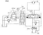
- FIG. 2 is a circuit diagram of a traveling hydraulic circuit in the wheeled hydraulic excavator shown in FIG. 1.
- This hydraulic circuit includes a main pump 24 driven by a prime mover 10, the traveling motor 5 driven with pressure oil form the main pump 24, a control valve 25 that controls a flow of the pressure oil from the main pump 24 to the traveling motor 5, a pilot pump 21, a pilot valve 22 driven via a foot-operated travel pedal 22a, and a forward/backward switching valve 23 that is switched to a forward position, a backward position or a neutral position in response to an operation of a forward/backward selector switch (not shown) .
- a pilot pressure originating from the pilot pump 21 is applied to the control valve 25.
- the pressure oil from the main pump 24 is applied to the traveling motor 5 via the control valve 25 and the traveling motor 5 rotates, thereby causing the vehicle to travel forward or backward.
- a pressure sensor 31 is connected to the pilot valve 22 and a pilot pressure Pt is detected as a travel command with the pressure sensor 31.
- FIG. 3 shows a hydraulic circuit for the boom cylinder, representing an example of a work hydraulic circuit.
- This hydraulic circuit includes a main pump 26, the boom cylinder 4d that is caused to extend/contract by pressure oil from the main pump 26, a control valve 27 that controls the flow of the pressure oil from the main pump 26 to the boom cylinder 4d, the pilot pump 21 and a pilot valve 28 driven via an operating lever 28a.
- hydraulic circuits of the other actuators for actuating the front attachment are similar to that described above.
- the pilot valve 28 In response to an operation of the operating lever 28a, the pilot valve 28 is driven in correspondence to the extent to which the operating lever 28a has been operated and a pilot pressure from the pilot pump 21 is applied to the control valve 27.
- a pilot pressure from the pilot pump 21 is applied to the control valve 27.
- the pressure oil from the main pump 26 is guided to the boom cylinder 4d via the control valve 27 and, as the boom cylinder 4d extends/contracts, the boom 4a is raised/lowered.
- the hydraulic circuit may dispense with the main pump 26 and, in such a case, the cylinder 4d can be driven with the pressure oil from the main pump 24.
- the engine rotation speed is controlled to adjust a delivery flow rate from the pump in a pedal mode (a first mode) or in a dial mode (a second mode) to be detailed later, so as to adjust the vehicle speed.
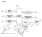
- FIG. 4 is a block diagram of a control circuit that controls the rotation speed of the engine.
- a governor lever 11 of an engine 10 is connected to a pulse motor 13 via a link mechanism 12 and the engine rotation speed is adjusted with the rotation of the pulse motor 13. Namely, the engine rotation speed increases as the pulse motor 13 rotates forward, and the engine rotation speed decreases with a reverse rotation of the pulse motor 13.
- a potentiometer 14 is connected to the governor lever 11 via the link mechanism 12, and the governor lever angle corresponding to the rotation speed of the engine 10, which is detected with the potentiometer 14, is input to the control circuit 30 as an engine control rotation speed N ⁇ .
- the control circuit 30 is connected with the pressure sensor 31 that detects the pilot pressure Pt corresponding to the extent to which the travel pedal 22a is operated, a brake switch 32, a position sensor 33 that detects the position to which the forward/backward switching valve 23 is switched, a manual or hand-operated set dial 34 that issues a signal for setting the engine rotation speed in accordance with an extent X to which the dial is turned, and a change-over switch 35 that changes over between the pedal mode and the dial mode selectively.
- a work or traveling signal is output from the brake switch 32.
- a parking brake is canceled and the operation of a service brake is enabled through a brake pedal.
- the parking brake and the service brake are both engaged.
- the parking brake is engaged.
- the brake switch 32 is switched to the traveling position, it outputs an off signal, whereas it outputs an on signal when it is switched to the work or parking position.
- the set dial 34 is installed in an operation panel in the vicinity of an operator's seat so as to be operatable during traveling.
- the change-over switch 35 is disposed adjacent to the set dial 34 so as to enable the operator to operate the change-over switch 35 without leaving his hand from the set dial 34.
- FIG. 7 One example of arrangement of the set dial 34 and the change-over switch 35 is shown in FIG. 7.
- the rotation speed control circuit 30 executes the following arithmetic operation and outputs a control signal to the pulse motor 13.
- FIG. 5 is a conceptual diagram illustrating in detail the rotation speed control circuit 30.
- the relationships between the detection value Pt provided by the pressure sensor 31 and a target rotation speed Nt and between the detection value Pt and a target rotation speed Nd are stored in memory in advance at rotation speed calculation units 41 and 42 respectively as shown in the figure, and the target rotation speeds Nt and Nd matching the extent to which the travel pedal 22a is operated are individually calculated based upon the characteristics of these relationships.
- the characteristics stored in memory at the rotation speed calculation unit 41 are the characteristics suited for traveling, whereas the characteristics stored in memory at the rotation speed calculation unit 42 are the characteristics suited for work performed by using the work attachment 4.
- the target rotation speed Nt increases in a steeper slope compared to the target rotation speed Nd, and a maximum value Ntmax of the target rotation speed Nt is greater than a maximum value Ndmax of the target rotation speed Nd.
- a selection unit 44 selects one of the target rotation speeds Nt and Nd provided by the rotation speed calculation units 41 and 42, based upon the signals provided from the brake switch 32, the position sensor 33 and the pressure sensor 31. If the brake switch 32 has been switched to the traveling position (an off signal is output), the forward/backward switching valve 23 is set at a position other than the neutral position and the pilot pressure Pt representing the extent of the operation of the travel pedal 22a is equal to or greater than a predetermined value, i. e., if the vehicle is traveling, the target rotation speed Nt is selected, and the target rotation speed Nd is selected otherwise, i.e., under non-traveling conditions.
- a maximum value selection unit 45 compares the target rotation speed Nt or Nd selected by the selection unit 44 with the target rotation speed Nx calculated at the rotation speed calculation unit 43 and selects the larger value as Nmax.
- a mode change unit 46 selects either the target rotation speed Nmax selected at the maximum value selection unit 45 or the target rotation speed Nx calculated at the rotation speed calculation unit 43, based upon the signal provided from the change-over switch 35.
- the target rotation speed Nmax is selected when the change-over switch 35 is switched to the pedal mode
- the target rotation speed Nx is selected when the change-over switch 35 is switched to the dial mode.
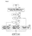
- a servo control unit 47 compares the rotation speed (the rotation speed command value Nin) selected at the mode change unit 46 with the control rotation speed N ⁇ corresponding to the displacement quantity of the governor lever 11 detected with the potentiometer 14. Then, it controls the pulse motor 13 through the procedure shown in FIG. 6 so as to match the two values.
- step S21 the rotation speed command value Nin and the control rotation speed N ⁇ are individually read in step S21 before proceeding to step S22 in FIG. 6. Then, in step S22, the results of subtracting Nin from N ⁇ are stored as a rotation speed difference A in memory, and in step S23, a decision is made as to whether or not
- the control rotation speed N ⁇ is greater than the rotation speed command value Nin, i.e., the control rotation speed is higher than the target rotation speed and, accordingly, a signal constituting a command for a motor reverse rotation is output to the pulse motor 13 in step S25 in order to lower the engine rotation speed.
- the pulse motor 13 rotates in the reverse direction, thereby lowering the engine rotation speed.
- step S26 a signal constituting a command for a motor forward rotation is output in step S26 in order to raise the engine rotation speed.
- the pulse motor 13 rotates forward, thereby raising the engine rotation speed.
- step S27 the operation proceeds to step S27 to output a motor stop signal and, as a result, the engine rotation speed is sustained at a constant level.
- the pedal mode is selected with the change-over switch 35.
- the engine rotation speed can be set in accordance with the operation of the travel pedal 22a and thus, the pedal mode is suitable for a normal travel during which a maximum torque may be generated.
- the brake switch 32 is set to the traveling position and the forward/backward selector switch is set to the forward position or the backward position when the vehicle is to travel.
- the control valve 25 is switched in correspondence to the extent of the pedal operation and the traveling motor 5 is caused to rotate by the pressure oil from the main pump 24.
- the target rotation speed Nt is selected through the arithmetic operation in the selection unit 44 of the control circuit 30, and the target rotation speed Nt is again selected in the maximum value selection unit 45.
- the target rotation speed Nt is set as the rotation speed command value Nin, and with the signal outputted through the servo control to the pulse motor 13, control is implemented to set the engine rotation speed equal to the target rotation speed Nt.
- the engine rotation speed is adjusted in conformance to the characteristics suitable for traveling stored in memory at the rotation speed calculation unit 41. As a result, an improvement in fuel efficiency and the noise reduction can be achieved as well as achieving desirable acceleration.
- the brake switch 32 To engage the vehicle in work in a state where the vehicle remains stopping, the brake switch 32 is set to the work position and the forward/backward selector switch is set to the neutral position. As the operating lever 28a is operated in this state, the control valve 27 is switched in correspondence to the extent to which the operating lever 28a is operated, thereby driving the boom cylinder 4d.
- the selection unit 44 selects the target rotation speed Nd and the maximum value selection unit 45 selects a larger value between the target rotation speed Nd and the target rotation speed Nx set by the set dial 34. Accordingly, by setting the target rotation speed Nx with the set dial 34 to a suitable value for the particular nature of work to be undertaken, a fluctuation of the engine rotation speed can be suppressed regardless of the operation of the travel pedal 22a and the excellent workability can be obtained.
- the dial mode is selected with the change-over switch 35.
- the engine rotation speed is set through the operation of the set dial 34 regardless of the operation of the travel pedal 22a, and the engine rotation speed is adjusted to the value set via the set dial 34 while no rotation speed is selected at the selection units 44 and 45 with reference to Fig. 5.
- the engine rotation speed is set via the set dial 34 and when the travel pedal 22a is depressed, only an extent to which the control valve 25 is switched changes to adjust the speed without changing the engine rotation speed.
- a speed based upon a maximum delivery flow rate of the main pump 24 corresponding to the set engine rotation speed can be set as a maximum speed, thereby making the dial mode suitable for a case where the travel speed should be limited below a predetermined level or for a case where the vehicle travels at a constant speed.
- the target rotation speed Nx set via the set dial 34 is selected at the mode change unit 46 in the dial mode, and the target rotation speed Nx is set as the rotation speed command value Nin.
- the engine rotation speed is controlled to the target rotation speed Nx regardless of the operation of the travel pedal 22a. Namely, the delivery flow rate of the pump changes according to the extent to which the dial is turned.
- the pressure oil according to the target rotation speed Nx is supplied to the traveling motor 5 so as to enable the maximum speed of the vehicle to be regulated in accordance with the operation of the set dial 34.
- the maximum travel speed rises as the engine rotation speed increases due to increase in the extent to which the dial is operated, whereas the maximum travel speed is lowered as the engine rotation speed decreases due to decrease in the dial operation amount.
- the vehicle can travel at a constant speed which is set at will while the travel pedal 22a is depressed to the maximum extent. As a result, there is no need for the operator to adjust the pedal operation amount, thereby reducing the burden on the operator.
- the control circuit may dispense with the target rotation speed calculation unit 42.
- the change-over switch 35 constitutes a selection means
- an operation member other than the switch for instance a dial
- the set dial 34 constitutes a second set member
- an operation member other than the dial for instance a push button switch or a slide switch which moves straight
- a travel state is determined based upon the signals from the brake switch 32 and the position sensor 33 working as a determination means, the travel state may be determined using, for instance a vehicle speed sensor.
- the maximum value selection unit 45 may be omitted as shown in FIG. 8.
- the engine rotation speed can be set in accordance with the operation of the travel pedal 22a regardless of the operation of the set dial 34 in the pedal mode, and the engine rotation speed can be set in accordance with the operation of the set dial 34 in the dial mode. That is, a separate engine control can be executed by using either the travel pedal 22a or the set dial 34.
- a first operating member is also not limited to the travel pedal 22a.
- a wheeled hydraulic excavator represents an example of a construction machine in which the present invention may be adopted
- the present invention may also be adopted in other types of construction machines such as non-wheel construction machines.
Landscapes
- Engineering & Computer Science (AREA)
- General Engineering & Computer Science (AREA)
- Mechanical Engineering (AREA)
- Mining & Mineral Resources (AREA)
- Civil Engineering (AREA)
- Structural Engineering (AREA)
- Chemical & Material Sciences (AREA)
- Combustion & Propulsion (AREA)
- Transportation (AREA)
- Physics & Mathematics (AREA)
- Fluid Mechanics (AREA)
- Automation & Control Theory (AREA)
- Operation Control Of Excavators (AREA)
- Control Of Vehicle Engines Or Engines For Specific Uses (AREA)
- Control Of Throttle Valves Provided In The Intake System Or In The Exhaust System (AREA)
- Combined Controls Of Internal Combustion Engines (AREA)
Abstract
Description
It is preferable that the selection member is installed in the vicinity of the second operating member. The actuator may be a traveling motor.
Claims (8)
- A prime mover control device of a construction machine that includes:a hydraulic pump driven by a prime mover;an actuator driven with pressure oil discharged from the hydraulic pump; anda control valve that controls a flow of the pressure oil from the hydraulic pump to the actuator in response to an operation of a first operating member, comprising:a first set means for setting a first set rotation speed of the prime mover according to the operation of the first operating member;a second set means for setting a second set rotation speed of the prime mover according to an operation of a second operating member;a selection member that selects one of a first mode and a second mode; anda rotation speed control means for controlling a prime mover rotation speed to match with a maximum value between the first set rotation speed and the second set rotation speed when the selection member selects the first mode, and for controlling the prime mover rotation speed to match with the second set rotation speed when the selection member selects the second mode.
- A prime mover control device of a construction machine that includes:a hydraulic pump driven by a prime mover;an actuator driven with pressure oil discharged from the hydraulic pump; anda control valve that controls a flow of the pressure oil from the hydraulic pump to the actuator in response to an operation of a first operating member, comprising:a first set means for setting a first set rotation speed of the prime mover according to the operation of the first operating member;a second set means for setting a second set rotation speed of the prime mover according to an operation of a second operating member; a selection member that selects one of a first mode and a second mode; anda rotation speed control means for controlling a prime mover rotation speed to match with the first set rotation speed when the selection member selects the first mode, and for controlling the prime mover rotation speed to match with the second set rotation speed when the selection member selects the second mode.
- A prime mover control device of a construction machine according to claim 1 or claim 2, wherein:the first operating member is a foot-operated operating member, and the second operating member is a hand-operated operating member.
- A prime mover control device of a construction machine according to any one of claims 1 through 3, wherein:the selection member is installed in the vicinity of the second operating member.
- A prime mover control device of a construction machine according to any one of claims 1 through 4, wherein:the actuator is a traveling motor.
- A prime mover control device of a construction machine according to claim 5, further comprising:a determination means for determining a traveling state and a work state; wherein:when the traveling state is determined with the determination means, the first set means sets the first set rotation speed to a larger value compared to a value to be set when the work state is determined.
- A prime mover control device of a construction machine according to claim 6, wherein:the determination means comprises a brake detection means for detecting a non-operating state of a brake and a neutral detection means for detecting a neutral operation of the first operating member, and determines the traveling state when the non-operating state of the brake and the neutral operation are detected.
- A wheeled hydraulic excavator, comprising:a hydraulic pump driven by a prime mover;an actuator driven with pressure oil discharged from the hydraulic pump;a control valve that controls a flow of the pressure oil from the hydraulic pump to the actuator in response to an operation of a first operating member; anda prime mover control device according to any one of claims 1 through 7.
Applications Claiming Priority (1)
| Application Number | Priority Date | Filing Date | Title |
|---|---|---|---|
| PCT/JP2002/009964 WO2004029434A1 (en) | 2002-09-26 | 2002-09-26 | Prime mover controller of construction machine |
Publications (3)
| Publication Number | Publication Date |
|---|---|
| EP1550803A1 true EP1550803A1 (en) | 2005-07-06 |
| EP1550803A4 EP1550803A4 (en) | 2007-04-25 |
| EP1550803B1 EP1550803B1 (en) | 2010-01-13 |
Family
ID=32040306
Family Applications (1)
| Application Number | Title | Priority Date | Filing Date |
|---|---|---|---|
| EP02807861A Expired - Lifetime EP1550803B1 (en) | 2002-09-26 | 2002-09-26 | Prime mover controller of construction machine |
Country Status (6)
| Country | Link |
|---|---|
| US (1) | US7886862B2 (en) |
| EP (1) | EP1550803B1 (en) |
| JP (1) | JP3936364B2 (en) |
| CN (1) | CN100354512C (en) |
| DE (1) | DE60235125D1 (en) |
| WO (1) | WO2004029434A1 (en) |
Cited By (5)
| Publication number | Priority date | Publication date | Assignee | Title |
|---|---|---|---|---|
| WO2011032911A1 (en) * | 2009-09-18 | 2011-03-24 | Valtra Oy Ab | Hydraulic fluid supply systems |
| EP2131027A4 (en) * | 2007-02-28 | 2012-10-17 | Hitachi Construction Machinery | MOTOR SPEED CONTROL DEVICE FOR HYDRAULIC DRIVING VEHICLE |
| EP2256260A3 (en) * | 2009-05-29 | 2014-06-18 | Kabushiki Kaisha Kobe Seiko Sho (Kobe Steel, Ltd.) | Controller for hydraulic pump horsepower and work machine provided therewith |
| EP2288510A4 (en) * | 2008-05-29 | 2018-04-11 | Scania CV AB (publ) | Engine speed control method |
| WO2023154276A1 (en) * | 2022-02-08 | 2023-08-17 | Clark Equipment Company | Power machine hand throttle and foot throttle control |
Families Citing this family (23)
| Publication number | Priority date | Publication date | Assignee | Title |
|---|---|---|---|---|
| JP3952994B2 (en) * | 2003-06-13 | 2007-08-01 | コベルコ建機株式会社 | Construction machinery |
| JP4732126B2 (en) * | 2005-10-28 | 2011-07-27 | 株式会社小松製作所 | Engine control device |
| JP4804137B2 (en) * | 2005-12-09 | 2011-11-02 | 株式会社小松製作所 | Engine load control device for work vehicle |
| JP4945137B2 (en) * | 2006-01-26 | 2012-06-06 | 本田技研工業株式会社 | Walking type work machine |
| JP4922881B2 (en) * | 2007-09-19 | 2012-04-25 | 株式会社小松製作所 | Engine control device |
| US8463509B2 (en) * | 2008-03-21 | 2013-06-11 | Komatsu Ltd. | Working vehicle, control device for working vehicle, and control method for working vehicle |
| KR100974279B1 (en) * | 2008-03-27 | 2010-08-06 | 볼보 컨스트럭션 이키프먼트 홀딩 스웨덴 에이비 | Heavy Equipment Driving System |
| JP5164933B2 (en) * | 2009-06-19 | 2013-03-21 | 日立建機株式会社 | Control device for work vehicle |
| JP5204726B2 (en) * | 2009-06-19 | 2013-06-05 | 日立建機株式会社 | Motor vehicle control device for work vehicle |
| JP5588206B2 (en) * | 2010-03-19 | 2014-09-10 | 三菱農機株式会社 | Work vehicle |
| US8362629B2 (en) * | 2010-03-23 | 2013-01-29 | Bucyrus International Inc. | Energy management system for heavy equipment |
| JP2013531753A (en) * | 2010-07-06 | 2013-08-08 | ボルボ コンストラクション イクイップメント アーベー | Horsepower control system and control method for hybrid excavator |
| US9097341B2 (en) * | 2012-01-26 | 2015-08-04 | Caterpillar Inc. | Brake system having a brake capacity test mode for a machine having a hydrostatic drivetrain |
| CN103046610B (en) * | 2012-12-28 | 2015-09-02 | 三一重机有限公司 | A kind of walk signal checkout gear and walking machine |
| CN105026654A (en) * | 2013-02-08 | 2015-11-04 | 沃尔沃建造设备有限公司 | Construction equipment driving control method |
| JP5920382B2 (en) * | 2014-02-28 | 2016-05-18 | コベルコクレーン株式会社 | Construction machinery |
| JP6873809B2 (en) * | 2017-04-28 | 2021-05-19 | 株式会社クボタ | Work machine |
| WO2018199027A1 (en) * | 2017-04-28 | 2018-11-01 | 株式会社クボタ | Work equipment |
| JP6837909B2 (en) * | 2017-04-28 | 2021-03-03 | 株式会社クボタ | Work machine |
| JP6682476B2 (en) * | 2017-06-29 | 2020-04-15 | 株式会社クボタ | Work machine |
| CN109252970B (en) * | 2018-09-18 | 2021-09-28 | 潍柴动力股份有限公司 | Engine rotating speed control method, engine and vehicle |
| CN110273767A (en) * | 2019-06-28 | 2019-09-24 | 三一汽车制造有限公司 | Control method, control system and the engineering machinery of dynamical system |
| JP7687811B2 (en) * | 2020-07-30 | 2025-06-03 | ヤンマーホールディングス株式会社 | Operation device, work vehicle, and operation control method |
Family Cites Families (29)
| Publication number | Priority date | Publication date | Assignee | Title |
|---|---|---|---|---|
| US3595343A (en) * | 1969-01-15 | 1971-07-27 | Clark Equipment Co | Control system for lift trucks |
| US3841423A (en) * | 1972-01-24 | 1974-10-15 | Clark Equipment Co | Hydrostatic propulsion system |
| US3827522A (en) * | 1973-08-10 | 1974-08-06 | Koehring Co | Fluid pressure actuated brake light switch |
| JPS60189642A (en) * | 1984-03-07 | 1985-09-27 | Toyoda Autom Loom Works Ltd | Engine speed control device for cargo handling vehicles |
| EP0432266B2 (en) | 1989-01-18 | 1997-08-13 | Hitachi Construction Machinery Co., Ltd. | Hydraulic driving unit for construction machinery |
| JP2772540B2 (en) | 1989-04-12 | 1998-07-02 | 油谷重工株式会社 | Travel control device for wheeled excavator |
| JPH03110150A (en) | 1989-09-26 | 1991-05-10 | Toppan Printing Co Ltd | Non-fogging film for food pakaging |
| JPH085315Y2 (en) * | 1990-02-26 | 1996-02-14 | 株式会社アイチコーポレーション | Work vehicle accelerator control device |
| JPH04143428A (en) | 1990-10-05 | 1992-05-18 | Komatsu Ltd | Controller for construction machinery |
| US5307631A (en) | 1991-01-28 | 1994-05-03 | Hitachi Construction Machinery Co., Ltd. | Hydraulic control apparatus for hydraulic construction machine |
| WO1992014046A1 (en) * | 1991-02-05 | 1992-08-20 | Hitachi Construction Machinery Co., Ltd. | System for controlling revolution frequency of prime mover in hydraulically driven vehicle |
| JP2634330B2 (en) | 1991-02-08 | 1997-07-23 | 日立建機株式会社 | Engine speed control device for hydraulically driven vehicle |
| US5638677A (en) * | 1991-03-29 | 1997-06-17 | Hitachi Construction Machinery Co., Ltd. | Control device for hydraulically propelled work vehicle |
| JP2884899B2 (en) | 1992-03-03 | 1999-04-19 | 油谷重工株式会社 | Running speed control method for construction machinery |
| JP3487358B2 (en) | 1993-07-14 | 2004-01-19 | 株式会社小松製作所 | Engine power and hydraulic pump absorption horsepower control device of hydraulic excavator |
| JP3654599B2 (en) * | 1994-09-09 | 2005-06-02 | 株式会社小松製作所 | Transmission device for hydraulic drive device and transmission control method therefor |
| JPH0988650A (en) * | 1995-09-14 | 1997-03-31 | Shin Caterpillar Mitsubishi Ltd | Engine speed switching device in working machine |
| WO1998006936A1 (en) | 1996-08-09 | 1998-02-19 | Komatsu Ltd. | Controller for engine and variable displacement hydraulic pump |
| JPH1089111A (en) | 1996-09-17 | 1998-04-07 | Yanmar Diesel Engine Co Ltd | Control mechanism of engine loaded with working machine |
| JP3511453B2 (en) * | 1997-10-08 | 2004-03-29 | 日立建機株式会社 | Control device for prime mover and hydraulic pump of hydraulic construction machine |
| JP2864241B2 (en) * | 1997-12-22 | 1999-03-03 | 株式会社小松製作所 | Control equipment for construction machinery |
| JP2000092949A (en) | 1998-09-22 | 2000-04-04 | Iseki & Co Ltd | Engine rotation control device for agricultural work vehicle |
| JP2000179372A (en) | 1998-12-15 | 2000-06-27 | Nissan Motor Co Ltd | Forklift vehicle speed control device |
| JP2001152921A (en) | 1999-11-19 | 2001-06-05 | Komatsu Ltd | Loading work vehicle |
| JP2002003154A (en) | 2000-06-27 | 2002-01-09 | Hitachi Constr Mach Co Ltd | Device for setting maximum speed of hydraulic motor of construction machine |
| JP4475767B2 (en) | 2000-08-03 | 2010-06-09 | 株式会社小松製作所 | Work vehicle |
| KR100527824B1 (en) * | 2000-09-08 | 2005-11-09 | 히다치 겡키 가부시키 가이샤 | Speed controller of wheel type hydraulic traveling vehicle |
| JP3686324B2 (en) * | 2000-10-20 | 2005-08-24 | 日立建機株式会社 | Hydraulic traveling vehicle |
| JP4015445B2 (en) | 2002-03-15 | 2007-11-28 | 日立建機株式会社 | Operation control device for wheel type construction machine |
-
2002
- 2002-09-26 WO PCT/JP2002/009964 patent/WO2004029434A1/en not_active Ceased
- 2002-09-26 JP JP2004539436A patent/JP3936364B2/en not_active Expired - Lifetime
- 2002-09-26 CN CNB028296680A patent/CN100354512C/en not_active Expired - Lifetime
- 2002-09-26 EP EP02807861A patent/EP1550803B1/en not_active Expired - Lifetime
- 2002-09-26 DE DE60235125T patent/DE60235125D1/en not_active Expired - Lifetime
- 2002-09-26 US US10/528,485 patent/US7886862B2/en not_active Expired - Fee Related
Cited By (8)
| Publication number | Priority date | Publication date | Assignee | Title |
|---|---|---|---|---|
| EP2131027A4 (en) * | 2007-02-28 | 2012-10-17 | Hitachi Construction Machinery | MOTOR SPEED CONTROL DEVICE FOR HYDRAULIC DRIVING VEHICLE |
| US8494733B2 (en) | 2007-02-28 | 2013-07-23 | Hitachi Construction Machinery Co., Ltd. | Prime mover rotation speed control system for hydraulically driven vehicle |
| EP2288510A4 (en) * | 2008-05-29 | 2018-04-11 | Scania CV AB (publ) | Engine speed control method |
| EP2256260A3 (en) * | 2009-05-29 | 2014-06-18 | Kabushiki Kaisha Kobe Seiko Sho (Kobe Steel, Ltd.) | Controller for hydraulic pump horsepower and work machine provided therewith |
| WO2011032911A1 (en) * | 2009-09-18 | 2011-03-24 | Valtra Oy Ab | Hydraulic fluid supply systems |
| US8734291B2 (en) | 2009-09-18 | 2014-05-27 | Valtra Oy Ab | Hydraulic fluid supply systems |
| WO2023154276A1 (en) * | 2022-02-08 | 2023-08-17 | Clark Equipment Company | Power machine hand throttle and foot throttle control |
| US12559912B2 (en) | 2022-02-08 | 2026-02-24 | Doosan Bobcat North America, Inc. | Power machine hand throttle and foot throttle control |
Also Published As
| Publication number | Publication date |
|---|---|
| CN1668834A (en) | 2005-09-14 |
| US7886862B2 (en) | 2011-02-15 |
| JP3936364B2 (en) | 2007-06-27 |
| JPWO2004029434A1 (en) | 2006-01-26 |
| US20060151230A1 (en) | 2006-07-13 |
| EP1550803A4 (en) | 2007-04-25 |
| CN100354512C (en) | 2007-12-12 |
| DE60235125D1 (en) | 2010-03-04 |
| WO2004029434A1 (en) | 2004-04-08 |
| EP1550803B1 (en) | 2010-01-13 |
Similar Documents
| Publication | Publication Date | Title |
|---|---|---|
| US7886862B2 (en) | Prime mover control device of construction machine | |
| EP1544440B1 (en) | Prime mover controller of a construction machine. | |
| JP3179786B2 (en) | Hydraulic pump control device | |
| JP2004144254A (en) | Hydraulic drive vehicle | |
| CN109073075B (en) | Working vehicle | |
| US7513110B2 (en) | Control apparatus of construction machine and method for calculating input torque | |
| US7607245B2 (en) | Construction machine | |
| JP3686324B2 (en) | Hydraulic traveling vehicle | |
| KR100805990B1 (en) | Controller for hydraulic drive system | |
| JP4282871B2 (en) | Hydraulic traveling vehicle | |
| JP4121687B2 (en) | Hydraulic traveling vehicle | |
| JP2572387B2 (en) | Hydraulic control device for wheel type hydraulic shovel | |
| JP4242038B2 (en) | Wheeled hydraulic construction machine | |
| JP4448777B2 (en) | Hydrostatic transmission vehicle and controller of hydrostatic transmission | |
| JPH11324026A (en) | Operator and actuator combination changing device and work mode changing device in construction machinery | |
| KR100680928B1 (en) | Prime Mover Control of Construction Machinery | |
| KR100680929B1 (en) | Prime Mover Control of Construction Machinery |
Legal Events
| Date | Code | Title | Description |
|---|---|---|---|
| PUAI | Public reference made under article 153(3) epc to a published international application that has entered the european phase |
Free format text: ORIGINAL CODE: 0009012 |
|
| 17P | Request for examination filed |
Effective date: 20050418 |
|
| AK | Designated contracting states |
Kind code of ref document: A1 Designated state(s): AT BE BG CH CY CZ DE DK EE ES FI FR GB GR IE IT LI LU MC NL PT SE SK TR |
|
| RIN1 | Information on inventor provided before grant (corrected) |
Inventor name: ICHIMURA, KAZUHIRO Inventor name: SATAKE, HIDETOSHI Inventor name: TATSUNO, YUKIHIRO |
|
| RIN1 | Information on inventor provided before grant (corrected) |
Inventor name: ICHIMURA, KAZUHIRO Inventor name: SATAKE, HIDETOSHI Inventor name: TATSUNO, YUKIHIRO |
|
| RBV | Designated contracting states (corrected) |
Designated state(s): DE FR GB IT NL SE |
|
| A4 | Supplementary search report drawn up and despatched |
Effective date: 20070323 |
|
| RIC1 | Information provided on ipc code assigned before grant |
Ipc: E02F 9/22 20060101AFI20070319BHEP |
|
| 17Q | First examination report despatched |
Effective date: 20071121 |
|
| GRAP | Despatch of communication of intention to grant a patent |
Free format text: ORIGINAL CODE: EPIDOSNIGR1 |
|
| GRAS | Grant fee paid |
Free format text: ORIGINAL CODE: EPIDOSNIGR3 |
|
| GRAA | (expected) grant |
Free format text: ORIGINAL CODE: 0009210 |
|
| AK | Designated contracting states |
Kind code of ref document: B1 Designated state(s): DE FR GB IT NL SE |
|
| REG | Reference to a national code |
Ref country code: GB Ref legal event code: FG4D |
|
| REF | Corresponds to: |
Ref document number: 60235125 Country of ref document: DE Date of ref document: 20100304 Kind code of ref document: P |
|
| REG | Reference to a national code |
Ref country code: NL Ref legal event code: T3 |
|
| PG25 | Lapsed in a contracting state [announced via postgrant information from national office to epo] |
Ref country code: SE Free format text: LAPSE BECAUSE OF FAILURE TO SUBMIT A TRANSLATION OF THE DESCRIPTION OR TO PAY THE FEE WITHIN THE PRESCRIBED TIME-LIMIT Effective date: 20100113 |
|
| PLBE | No opposition filed within time limit |
Free format text: ORIGINAL CODE: 0009261 |
|
| STAA | Information on the status of an ep patent application or granted ep patent |
Free format text: STATUS: NO OPPOSITION FILED WITHIN TIME LIMIT |
|
| 26N | No opposition filed |
Effective date: 20101014 |
|
| REG | Reference to a national code |
Ref country code: FR Ref legal event code: ST Effective date: 20110531 |
|
| PG25 | Lapsed in a contracting state [announced via postgrant information from national office to epo] |
Ref country code: FR Free format text: LAPSE BECAUSE OF NON-PAYMENT OF DUE FEES Effective date: 20100930 |
|
| PGFP | Annual fee paid to national office [announced via postgrant information from national office to epo] |
Ref country code: GB Payment date: 20160921 Year of fee payment: 15 Ref country code: IT Payment date: 20160921 Year of fee payment: 15 |
|
| GBPC | Gb: european patent ceased through non-payment of renewal fee |
Effective date: 20170926 |
|
| PG25 | Lapsed in a contracting state [announced via postgrant information from national office to epo] |
Ref country code: GB Free format text: LAPSE BECAUSE OF NON-PAYMENT OF DUE FEES Effective date: 20170926 |
|
| PG25 | Lapsed in a contracting state [announced via postgrant information from national office to epo] |
Ref country code: IT Free format text: LAPSE BECAUSE OF NON-PAYMENT OF DUE FEES Effective date: 20170926 |
|
| PGFP | Annual fee paid to national office [announced via postgrant information from national office to epo] |
Ref country code: NL Payment date: 20210813 Year of fee payment: 20 |
|
| PGFP | Annual fee paid to national office [announced via postgrant information from national office to epo] |
Ref country code: DE Payment date: 20210818 Year of fee payment: 20 |
|
| REG | Reference to a national code |
Ref country code: DE Ref legal event code: R071 Ref document number: 60235125 Country of ref document: DE |
|
| REG | Reference to a national code |
Ref country code: NL Ref legal event code: MK Effective date: 20220925 |