EP1550622B1 - Vibratory conveyor deck - Google Patents
Vibratory conveyor deck Download PDFInfo
- Publication number
- EP1550622B1 EP1550622B1 EP04029671A EP04029671A EP1550622B1 EP 1550622 B1 EP1550622 B1 EP 1550622B1 EP 04029671 A EP04029671 A EP 04029671A EP 04029671 A EP04029671 A EP 04029671A EP 1550622 B1 EP1550622 B1 EP 1550622B1
- Authority
- EP
- European Patent Office
- Prior art keywords
- deck
- conveyor
- force
- rib
- coupled
- Prior art date
- Legal status (The legal status is an assumption and is not a legal conclusion. Google has not performed a legal analysis and makes no representation as to the accuracy of the status listed.)
- Not-in-force
Links
Images


Classifications
-
- B—PERFORMING OPERATIONS; TRANSPORTING
- B65—CONVEYING; PACKING; STORING; HANDLING THIN OR FILAMENTARY MATERIAL
- B65G—TRANSPORT OR STORAGE DEVICES, e.g. CONVEYORS FOR LOADING OR TIPPING, SHOP CONVEYOR SYSTEMS OR PNEUMATIC TUBE CONVEYORS
- B65G27/00—Jigging conveyors
- B65G27/04—Load carriers other than helical or spiral channels or conduits
-
- B—PERFORMING OPERATIONS; TRANSPORTING
- B65—CONVEYING; PACKING; STORING; HANDLING THIN OR FILAMENTARY MATERIAL
- B65G—TRANSPORT OR STORAGE DEVICES, e.g. CONVEYORS FOR LOADING OR TIPPING, SHOP CONVEYOR SYSTEMS OR PNEUMATIC TUBE CONVEYORS
- B65G27/00—Jigging conveyors
- B65G27/02—Jigging conveyors comprising helical or spiral channels or conduits for elevation of materials
-
- B—PERFORMING OPERATIONS; TRANSPORTING
- B65—CONVEYING; PACKING; STORING; HANDLING THIN OR FILAMENTARY MATERIAL
- B65G—TRANSPORT OR STORAGE DEVICES, e.g. CONVEYORS FOR LOADING OR TIPPING, SHOP CONVEYOR SYSTEMS OR PNEUMATIC TUBE CONVEYORS
- B65G2207/00—Indexing codes relating to constructional details, configuration and additional features of a handling device, e.g. Conveyors
- B65G2207/24—Helical or spiral conveying path
Definitions
- This disclosure generally relates to vibratory process equipment and, more particularly, to decks used in vibratory conveyors.
- a vibratory conveyor as defined in the precharacterising part of claim 1 is known from US-A 4787502 .
- Vibratory conveyors are generally known in the art for transporting objects using a vibratory force.
- Such conveyors typically include a deck or other structure that has a conveying surface which defines a path along which objects are conveyed.
- the path defined by the deck may be straight, curved, inclined, declined, spiral, or other configuration.
- the deck is typically constructed of plate steel. As a result, when viewed in cross-section, the conveying surface defined by the deck is typically “flat” across the width of the deck. Stated alternatively, the conveying surface is substantially linear across its width.
- While a flat deck is satisfactory for many applications, it may cause unintended and undesirable results when used to convey certain objects.
- the objects may roll transversely across the width of the deck, and therefore are not located on the deck with any degree of certainty.
- the cylindrical objects may become oriented transversely across the deck, and therefore more easily roll into and possibly damage other objects on the deck.
- the invention is defined by a vibratory conveyor according to claim 1.
- Advantageous embodiments of this invention are defined independent claims 2 to 10.
- a conveyor deck having a conveying surface and a back surface.
- a rib is attached to the back surface and a "force assembly" is coupled to the rib.
- the deck may be bowed either concavely or convexly. If formed with a concave bend, the conveying surface of the deck, when viewed in cross-section, will have a localized low point adjacent the rib that defines a deck along which objects are conveyed.
- the concave shape also tends to orient cylindrical objects longitudinally on the deck, defined herein as parallel to the direction of travel.
- the bowed cross-sectional shape allows the deck to be formed more nearly to a pure helicoid, where the pitch of the deck is consistent along the entire conveyor path and each radial cross section of the deck will have linear opposing deck edges, regardless of whether the deck is curved concavely or convexly. While the disclosed embodiment is a spiral conveyor, it will be appreciated that the bowed deck shape provides advantages for other conveyor path configurations, including linear, curved, and inclined paths.
- a spiral conveyor 10 having a frame 12 supporting a spiral deck 16.
- the frame 12 is resiliently supported above the ground or mounting surface by isolation means, such as springs 18.
- An exciter mass 20 and vibration generators 22 are resiliently coupled to the frame 12, such as by springs 21 (FIG. 2).
- Any generally known vibration generators may be used, such as motors having rotating shafts carrying eccentric weights.
- the spiral deck 16 is oriented to vertically elevate work pieces, such as hot castings, from an inlet 24 to an outlet 26.
- the deck 16 defines a conveying surface 16a for receiving the work pieces and a back surface 16b (FIGS. 4 & 5).
- the work pieces may be transferred from an origination point, such as a molding line, to the inlet 24 by any conveying means, such as by a linear vibratory or other type of conveyor (not shown).
- the spiral deck 16 is formed in a helical pattern so that, as the work pieces move circumferentially around the deck, they are also elevated in the vertical direction.
- the spiral deck 16 defines a plurality of stacked tier segments 14.
- the work piece may be deposited onto an outlet transport (not shown), which may also be a conveyor. While the conveyor 10 is described herein as conveying the work pieces vertically upward, the inlet and outlet may be reversed so that the work pieces are conveyed vertically downward along the spiral deck 16.
- the vibration generators 22 may be controlled in any known fashion to produce the desired vibrational motion of the frame 12 and coupled spiral deck 16, thereby to advance the work pieces along the deck 16.
- the motors may be rotated in opposite directions (i.e., counter-rotated) and controlled to maintain a desired phase angle between the eccentric weights. While the illustrated embodiment is a two mass system, it will be appreciated that the conveyor 10 may be provided as a single mass or brute force system.
- the spiral deck 16 includes an inner edge 19 and an outer edge 21.
- An inner housing wall 30 is coupled to the spiral deck inner edge 19 and an outer housing wall 32 is coupled to the spiral deck outer edge 21.
- the deck inner edge 19 is secured to the inner housing wall 30 by a first or inner wall support assembly 34, which may clamp the deck inner edge 19 between a bottom flange 36 and a top retainer 38 (FIG. 5).
- the deck outer edge 21 may be secured to the outer housing wall 32 by a second or outer wall support assembly 40, which may clamp the deck outer edge 21 between a bottom flange 42 and a top retainer 44.
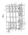
- a plurality of access doors 46 (FIG. 1) may be formed in the housing outer wall 32 for accessing the different tier portions 14 of the deck 16, should the outer housing wall 32 completely enclose the deck 16.
- a rib assembly 50 is attached to the deck back surface 16b between the inner and outer deck edges 19, 21 (FIGS. 4-6).
- the rib assembly may 50 may extend continuously along the deck 16 in the longitudinal direction, so that, in the illustrated embodiment, the rib assembly has a spiral shape.
- the rib assembly 50 may include a pair of ribs 52 having aligned transverse apertures.
- a force assembly 60 coupled to the rib assembly 50 to create a force that bends the deck 16 into an arcuate shape when viewed in cross-section.
- the exemplary force assembly 60 includes a pin 62 mechanically coupled to the rib assembly 50, such as by insertion through the transverse apertures formed in the ribs 52.
- a cross support 64 is spaced from the deck 16 and supported by the inner and outer housing walls 30, 32. As shown, the cross support 64 is provided as a tubular steel member, and has apertures 65 formed in the upper and lower support surfaces 64a, 64b.
- a link 66 is inserted through the apertures in the cross support 64 and defines a first end 68 coupled to the pin 62 and a second end 70. The link 66 also includes a threaded portion 72 for receiving a nut 74.
- the nut 74 may be adjusted on the link threaded portion 72 to generate a force in the link 66 that is transferred by the rib assembly 50 to the deck 16, thereby to bend the deck 16 in an arcuate shape. As shown in FIGS. 4 & 5, the nut 74 may be located below the cross support 64. In FIG. 4, the deck 16 is shown in a relaxed state, where the force assembly 60 applies no force to the deck 16. The nut 74 may be adjusted upwardly along the threaded portion 72 so that the nut engages the lower surface of the cross support 64, thereby to create tension in the link 66. The tension in the link 66 is transferred by the pin 62 as a downwardly directed force acting against the rib assembly 50 and attached deck 16. The nut 74 may be adjusted along the threaded portion 72 to create a tension force in the link 66 sufficient to bend the deck 16 into an arcuate shape, as shown in FIG. 5.
- the pin 62 may be provided as a bar coupled to the ribs 52 and formed with a threaded aperture.
- the link 66 may be a bolt or threaded rod with the first end 68 threadably engaging the bar threaded aperture.
- the second end 70 of the bolt is a bolt head, which takes the place of the nut 74. Accordingly, bolt may be threaded into the bar threaded aperture to create the tension force.
- the ribs 52 may project sufficiently past the pin 62 to define stop ends 76 that are engageable with the top surface 64a of the cross support, thereby to limit the amount of deflection of the deck 16.
- the rib stop ends 76 are spaced from the top surface of the cross support by a known distance "D".
- the stop ends 76 are drawn toward and eventually engage the cross support top surface 64a, thereby limiting the amount of deflection of the deck 16.
- the conveying surface 16a may also be formed with a convex arcuate shape.
- the force assembly 60 may be modified so that the link threaded portion 72 is adjacent an upper surface of the cross support 64, and the nut 74 may be adjusted downwardly along the threaded portion to engage the upper surface 64a of the cross support. Consequently, a compression force is generated in the link 66 that is transferred by the pin 62 as an upwardly directed force against the rib assembly 60 and attached deck 16.
- a nut may simply be provided on the bolt above the cross support upper surface 64a, and the nut may be adjusted downwardly along the bolt to engage the upper surface 64a.
- FIGS. 4 & 5 While only a single force assembly 60 is shown coupled to the rib assembly 60 in FIGS. 4 & 5, it will be appreciated that a plurality of force assemblies may be coupled to the rib assembly 60 at points spaced along the longitudinal length of the rib assembly 50. In the segment of the deck 16 shown in FIG. 6, a total of three force assemblies 60 are shown coupled to the rib assembly 50. FIG. 6 also illustrates the ribs 62 extending along the longitudinal length of the deck 16. Furthermore, while a single deck segment is shown in FIG. 6, it will be appreciated that multiple deck segments may be fabricated independently and assembled to create the complete conveyor deck. The improved fit of the arcuate shaped deck allows the ends of the deck segments to be more reliably located, thereby facilitating assembly of mating deck segments.
Abstract
Description
- This disclosure generally relates to vibratory process equipment and, more particularly, to decks used in vibratory conveyors. A vibratory conveyor as defined in the precharacterising part of claim 1 is known from
US-A 4787502 . - Vibratory conveyors are generally known in the art for transporting objects using a vibratory force. Such conveyors typically include a deck or other structure that has a conveying surface which defines a path along which objects are conveyed. Depending on the application, the path defined by the deck may be straight, curved, inclined, declined, spiral, or other configuration.
- The deck is typically constructed of plate steel. As a result, when viewed in cross-section, the conveying surface defined by the deck is typically "flat" across the width of the deck. Stated alternatively, the conveying surface is substantially linear across its width.
- While a flat deck is satisfactory for many applications, it may cause unintended and undesirable results when used to convey certain objects. For example, when conveying generally cylindrical objects such as cam shafts along a flat deck, the objects may roll transversely across the width of the deck, and therefore are not located on the deck with any degree of certainty. In addition, the cylindrical objects may become oriented transversely across the deck, and therefore more easily roll into and possibly damage other objects on the deck.
- Flat decks are also difficult to employ for certain path configurations. In a spiral conveyor, for example, it is preferable to form the deck in a helicoid shape. To approximate the helicoid shape with flat plate steel, several bends such as cross crimps are typically formed in the deck. Such cross crimps, however, create abrupt changes in the pitch of the deck and cause the conveying surface to be non-linear across its width. Consequently, the cross-crimps create localized high wear area and non-uniform stresses in the deck. These problems are exacerbated during thermal expansion and contraction, which can be significant when the spiral conveyor is used for heating or cooling of the objects being conveyed. In addition, the need for cross crimps or other bends in the deck increases manufacturing costs and makes assembly more difficult, especially for conveyors that are constructed as multiple subassemblies that are mated together, such as for large conveyor sizes.
- The invention is defined by a vibratory conveyor according to claim 1. Advantageous embodiments of this invention are defined independent claims 2 to 10.
-
- FIG. 1 is a side elevation view of a vibratory spiral conveyor constructed in accordance with the teachings of the present disclosure.
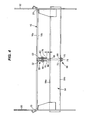
- FIG. 2 is an enlarged, partially schematic, sectional side view of the conveyor of FIG. 1.
- FIG. 3 is a plan view of the conveyor of FIG. 1.
- FIG. 4 is an enlarged sectional side view of a portion of the conveyor deck before the bending force is applied to the deck.
- FIG. 5 is an enlarged sectional side view of a portion of the conveyor deck with a bending force applied to the deck.
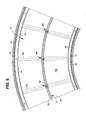
- FIG. 6 is a plan view of a section of the deck.
- A conveyor deck is disclosed herein having a conveying surface and a back surface. A rib is attached to the back surface and a "force assembly" is coupled to the rib. By applying a force to the rib with the force assembly, the deck may be bowed either concavely or convexly. If formed with a concave bend, the conveying surface of the deck, when viewed in cross-section, will have a localized low point adjacent the rib that defines a deck along which objects are conveyed. The concave shape also tends to orient cylindrical objects longitudinally on the deck, defined herein as parallel to the direction of travel. Additionally, when used in a spiral conveyor, the bowed cross-sectional shape allows the deck to be formed more nearly to a pure helicoid, where the pitch of the deck is consistent along the entire conveyor path and each radial cross section of the deck will have linear opposing deck edges, regardless of whether the deck is curved concavely or convexly. While the disclosed embodiment is a spiral conveyor, it will be appreciated that the bowed deck shape provides advantages for other conveyor path configurations, including linear, curved, and inclined paths.
- Referring to FIGS. 1 and 2, a
spiral conveyor 10 is shown having aframe 12 supporting aspiral deck 16. Theframe 12 is resiliently supported above the ground or mounting surface by isolation means, such assprings 18. Anexciter mass 20 andvibration generators 22 are resiliently coupled to theframe 12, such as by springs 21 (FIG. 2). Any generally known vibration generators may be used, such as motors having rotating shafts carrying eccentric weights. - In the illustrated embodiment, the
spiral deck 16 is oriented to vertically elevate work pieces, such as hot castings, from aninlet 24 to anoutlet 26. Thedeck 16 defines aconveying surface 16a for receiving the work pieces and aback surface 16b (FIGS. 4 & 5). The work pieces may be transferred from an origination point, such as a molding line, to theinlet 24 by any conveying means, such as by a linear vibratory or other type of conveyor (not shown). Thespiral deck 16 is formed in a helical pattern so that, as the work pieces move circumferentially around the deck, they are also elevated in the vertical direction. When theconveyor 10 is viewed in elevational cross-section, as schematically shown in FIG. 2, thespiral deck 16 defines a plurality of stackedtier segments 14. At theoutlet 26, the work piece may be deposited onto an outlet transport (not shown), which may also be a conveyor. While theconveyor 10 is described herein as conveying the work pieces vertically upward, the inlet and outlet may be reversed so that the work pieces are conveyed vertically downward along thespiral deck 16. - The
vibration generators 22 may be controlled in any known fashion to produce the desired vibrational motion of theframe 12 and coupledspiral deck 16, thereby to advance the work pieces along thedeck 16. For example, the motors may be rotated in opposite directions (i.e., counter-rotated) and controlled to maintain a desired phase angle between the eccentric weights. While the illustrated embodiment is a two mass system, it will be appreciated that theconveyor 10 may be provided as a single mass or brute force system. - As best shown with reference to FIGS. 3-6, the
spiral deck 16 includes aninner edge 19 and anouter edge 21. Aninner housing wall 30 is coupled to the spiral deckinner edge 19 and anouter housing wall 32 is coupled to the spiral deckouter edge 21. More specifically, the deckinner edge 19 is secured to theinner housing wall 30 by a first or inner wall support assembly 34, which may clamp the deckinner edge 19 between abottom flange 36 and a top retainer 38 (FIG. 5). Similarly, the deckouter edge 21 may be secured to theouter housing wall 32 by a second or outerwall support assembly 40, which may clamp the deckouter edge 21 between a bottom flange 42 and atop retainer 44. A plurality of access doors 46 (FIG. 1) may be formed in the housingouter wall 32 for accessing thedifferent tier portions 14 of thedeck 16, should theouter housing wall 32 completely enclose thedeck 16. - A
rib assembly 50 is attached to thedeck back surface 16b between the inner andouter deck edges 19, 21 (FIGS. 4-6). The rib assembly may 50 may extend continuously along thedeck 16 in the longitudinal direction, so that, in the illustrated embodiment, the rib assembly has a spiral shape. Therib assembly 50 may include a pair ofribs 52 having aligned transverse apertures. - A
force assembly 60 coupled to therib assembly 50 to create a force that bends thedeck 16 into an arcuate shape when viewed in cross-section. Theexemplary force assembly 60 includes apin 62 mechanically coupled to therib assembly 50, such as by insertion through the transverse apertures formed in theribs 52. Across support 64 is spaced from thedeck 16 and supported by the inner andouter housing walls cross support 64 is provided as a tubular steel member, and hasapertures 65 formed in the upper andlower support surfaces link 66 is inserted through the apertures in thecross support 64 and defines afirst end 68 coupled to thepin 62 and asecond end 70. Thelink 66 also includes a threadedportion 72 for receiving anut 74. - The
nut 74 may be adjusted on the link threadedportion 72 to generate a force in thelink 66 that is transferred by therib assembly 50 to thedeck 16, thereby to bend thedeck 16 in an arcuate shape. As shown in FIGS. 4 & 5, thenut 74 may be located below thecross support 64. In FIG. 4, thedeck 16 is shown in a relaxed state, where theforce assembly 60 applies no force to thedeck 16. Thenut 74 may be adjusted upwardly along the threadedportion 72 so that the nut engages the lower surface of thecross support 64, thereby to create tension in thelink 66. The tension in thelink 66 is transferred by thepin 62 as a downwardly directed force acting against therib assembly 50 and attacheddeck 16. Thenut 74 may be adjusted along the threadedportion 72 to create a tension force in thelink 66 sufficient to bend thedeck 16 into an arcuate shape, as shown in FIG. 5. - In an alternative embodiment, the
pin 62 may be provided as a bar coupled to theribs 52 and formed with a threaded aperture. Thelink 66 may be a bolt or threaded rod with thefirst end 68 threadably engaging the bar threaded aperture. Thesecond end 70 of the bolt is a bolt head, which takes the place of thenut 74. Accordingly, bolt may be threaded into the bar threaded aperture to create the tension force. - The
ribs 52 may project sufficiently past thepin 62 to define stop ends 76 that are engageable with thetop surface 64a of the cross support, thereby to limit the amount of deflection of thedeck 16. As shown in FIG. 4, when thedeck 16 is in the relaxed state, the rib stop ends 76 are spaced from the top surface of the cross support by a known distance "D". As thenut 74 is tightened to deflect thedeck 16, the stop ends 76 are drawn toward and eventually engage the cross supporttop surface 64a, thereby limiting the amount of deflection of thedeck 16. - While the illustrated embodiment shows the
deck conveying surface 16a bent into a concave arcuate shape, the conveying surface may also be formed with a convex arcuate shape. To do so, theforce assembly 60 may be modified so that the link threadedportion 72 is adjacent an upper surface of thecross support 64, and thenut 74 may be adjusted downwardly along the threaded portion to engage theupper surface 64a of the cross support. Consequently, a compression force is generated in thelink 66 that is transferred by thepin 62 as an upwardly directed force against therib assembly 60 and attacheddeck 16. - To create the compression force in the alternative embodiment described above, a nut may simply be provided on the bolt above the cross support
upper surface 64a, and the nut may be adjusted downwardly along the bolt to engage theupper surface 64a. - While only a
single force assembly 60 is shown coupled to therib assembly 60 in FIGS. 4 & 5, it will be appreciated that a plurality of force assemblies may be coupled to therib assembly 60 at points spaced along the longitudinal length of therib assembly 50. In the segment of thedeck 16 shown in FIG. 6, a total of threeforce assemblies 60 are shown coupled to therib assembly 50. FIG. 6 also illustrates theribs 62 extending along the longitudinal length of thedeck 16. Furthermore, while a single deck segment is shown in FIG. 6, it will be appreciated that multiple deck segments may be fabricated independently and assembled to create the complete conveyor deck. The improved fit of the arcuate shaped deck allows the ends of the deck segments to be more reliably located, thereby facilitating assembly of mating deck segments. - While a spiral conveyor path has been described and illustrated, the present disclosure is applicable to other conveyor path configurations requiring different deck shapes, such as linear, inclined, or curved decks, while still providing some or all of the benefits described herein. Still further, multiple concentric (in the case of curved or spiral path configurations) or parallel (in the case of linear path configurations) rib assemblies may be attached to the
deck 16 or adjacent sub-decks, each of which having force assemblies coupled thereto, so that the deck is bent with multiple arcs defining multiple lanes for transporting a column of objects. - Although certain apparatus constructed in accordance with the teachings of the disclosure have been described herein, the scope of coverage of this patent is not limited thereto. On the contrary, this patent covers all embodiments of the teachings of the disclosure fairly falling within the scope of the appended claims either literally or under the doctrine of equivalents.
Claims (10)
- A vibratory conveyor for transporting an object, the conveyor comprising:a first housing wall (30) having a first wall support (34);a second housing wall (32) having a second wall support (40);a deck (16) having a first lateral edge (19) engaging the first wall support (34) and a second lateral edge (21) engaging the second wall support (40), the deck (16) extending along a deck path and defining a conveyor surface adapted to receive the object; anda vibration generator (22) coupled to the deck (16) and producing vibrational motion of the deck (16) to thereby advance the object therealong,
characterized bya force assembly (60) mechanically coupled to the deck (16), the force assembly (60) applying a force that bends the deck (16) into an adjustable arcuate cross-sectional profile. - The conveyor of claim 1, in which the deck (16) includes a rib (52) extending longitudinally along the deck path, in which the force assembly (60) is mechanically coupled to the rib (52).
- The conveyor of claim 2, in which the force assembly (60) comprises a pin (62) coupled to the rib (52), a cross support (64) spaced from the deck (16) and defining an aperture (65), a link (66) inserted through the cross support aperture (65) having a first end (68) coupled to the pin (62) and a threaded portion (72), and a nut (74) threadably engaged with the link threaded portion (72), wherein the nut (74) is adjusted along the threaded portion (72) to create the force.
- The conveyor of claim 3, in which the nut (74) is adjusted to create a resultant tension force in the link (66).
- The conveyor of claim 4, in which the force bends the deck (16) so that the conveying surface has a concave arcuate profile.
- The conveyor of claim 3, in which the rib (52) projects past the pin (62) to define a stop end (76), wherein the stop end (76) engages the cross-support (64) to limit deflection of the deck (16).
- The conveyor of claim 2, in which the rib (52) extends along a longitudinal length of the deck (16).
- The conveyor of claim 7, in which a plurality of force assemblies (60) is coupled to the rib (52) at points spaced along the rib (52).
- The conveyor of claim 1, in which each of the first and second wall supports (34, 40) comprises a bottom flange (36, 42) and a top retainer (38, 44).
- The conveyor of claim 1, in which the deck path has a spiral configuration and the conveying surface (16a) is formed as a helicoid.
Applications Claiming Priority (2)
| Application Number | Priority Date | Filing Date | Title |
|---|---|---|---|
| US53232703P | 2003-12-23 | 2003-12-23 | |
| US532327P | 2003-12-23 |
Publications (2)
| Publication Number | Publication Date |
|---|---|
| EP1550622A1 EP1550622A1 (en) | 2005-07-06 |
| EP1550622B1 true EP1550622B1 (en) | 2007-07-18 |
Family
ID=34573057
Family Applications (1)
| Application Number | Title | Priority Date | Filing Date |
|---|---|---|---|
| EP04029671A Not-in-force EP1550622B1 (en) | 2003-12-23 | 2004-12-15 | Vibratory conveyor deck |
Country Status (8)
| Country | Link |
|---|---|
| US (1) | US7487868B2 (en) |
| EP (1) | EP1550622B1 (en) |
| JP (1) | JP2005179065A (en) |
| AT (1) | ATE367337T1 (en) |
| AU (1) | AU2004240148A1 (en) |
| BR (1) | BRPI0405794A (en) |
| CA (1) | CA2490324A1 (en) |
| DE (1) | DE602004007609T2 (en) |
Families Citing this family (4)
| Publication number | Priority date | Publication date | Assignee | Title |
|---|---|---|---|---|
| US7296951B2 (en) * | 2004-08-25 | 2007-11-20 | General Kinematics Corporation | Vibratory spiral conveyor |
| WO2013109868A1 (en) * | 2012-01-20 | 2013-07-25 | Mayfran International, Inc. | Vertical spiral conveyor |
| US9321117B2 (en) | 2014-03-18 | 2016-04-26 | Vermeer Manufacturing Company | Automatic system for abrasive hardfacing |
| CN109353760B (en) * | 2018-12-13 | 2020-09-11 | 温州市聚达信息科技有限公司 | Intelligent manufacturing system of beauty cosmetics |
Family Cites Families (45)
| Publication number | Priority date | Publication date | Assignee | Title |
|---|---|---|---|---|
| US2688394A (en) * | 1951-06-18 | 1954-09-07 | Hurd And James Inc | Belt conveyer for loose aggregates |
| US2927683A (en) | 1957-12-26 | 1960-03-08 | Carrier Conveyor Corp | Drive for a helical vibratory conveyor |
| US3087602A (en) | 1960-05-25 | 1963-04-30 | Hooker Chemical Corp | Conveyor apparatus |
| DE1800588A1 (en) * | 1968-10-02 | 1970-06-11 | Bosch Gmbh Robert | Oscillator driven by at least one unbalance exciter |
| US3664487A (en) | 1969-05-23 | 1972-05-23 | Carl H Ballenger | Endless helical conveyer and belt |
| US3850288A (en) | 1969-07-22 | 1974-11-26 | Gen Kinematics Corp | Vertical lift conveyor |
| DE2037371C3 (en) | 1969-07-22 | 1975-05-28 | General Kinematics Corp., Barrington, Ill. (V.St.A.) | Vertical vibratory conveyor for conveying lumpy or granular material |
| US3712459A (en) | 1971-02-12 | 1973-01-23 | Gen Kinematics Corp | Vibratory conveyor |
| US3776352A (en) | 1971-07-08 | 1973-12-04 | Gen Kinematics Corp | Sealed drive for vibratory material handling device |
| US3789977A (en) * | 1972-01-14 | 1974-02-05 | Gen Kinematics Corp | Vibratory vertical lift conveyor |
| US4140215A (en) | 1974-08-05 | 1979-02-20 | General Kinematics Corporation | Method of achieving vertical lift of particulate material |
| US4181216A (en) | 1977-11-25 | 1980-01-01 | George Cipu | Reversible vibrator, bowl feeder with angled spring supports |
| US4267919A (en) | 1979-05-21 | 1981-05-19 | Rexnord Inc. | Vibrating spiral conveyor drive |
| US4611709A (en) | 1979-07-02 | 1986-09-16 | General Kinematics | Vibratory conveyor |
| US4482046A (en) | 1982-04-15 | 1984-11-13 | General Kinematics Corporation | Flexible trough vibratory conveyor |
| US4709507A (en) | 1985-09-19 | 1987-12-01 | General Kinematics Corporation | Tumbling apparatus |
| US4787502A (en) | 1986-08-04 | 1988-11-29 | Triple/S Dynamics Inc. | Apparatus and method for conveying material |
| US4787504A (en) * | 1986-10-06 | 1988-11-29 | Ppg Industries, Inc. | Adjustable radius conveyor roll |
| US4775284A (en) | 1986-12-02 | 1988-10-04 | General Kinematics Corporation | Vertical mass flow conveyor |
| EP0287860A3 (en) * | 1987-03-31 | 1989-06-07 | Asmo Co., Ltd. | Mechanism converting rotary motion into reciprocating motion |
| US5024320A (en) | 1987-05-08 | 1991-06-18 | General Kinematics Corporation | Vibratory spiral elevator |
| US4844236A (en) | 1987-07-13 | 1989-07-04 | General Kinematics Corporation | Inclined vibratory conveyor |
| US4875343A (en) | 1988-03-14 | 1989-10-24 | Jeppsson E Hakan O | Climate chamber with conveyor |
| US5054606A (en) | 1988-05-11 | 1991-10-08 | General Kinematics Corporation | Control system for vibratory apparatus |
| WO1989012012A1 (en) * | 1988-06-05 | 1989-12-14 | Kabushikikaisha Yoko | Transfer apparatus for belt conveyor |
| US4926601A (en) | 1989-03-09 | 1990-05-22 | General Kinematics Corporation | Vibratory tumbling apparatus |
| US4953365A (en) | 1989-06-28 | 1990-09-04 | Liquid Carbonic Corporation | Helical conveyor freezer |
| GB2235756A (en) | 1989-09-05 | 1991-03-13 | Star Refrigeration | Helical refrigeration apparatus |
| DE4106712C1 (en) | 1991-03-02 | 1992-06-25 | Joest Gmbh + Co Kg, 4408 Duelmen, De | Spiral conveyor with vibration drive - has tubular guide above conveyed material, whose gas outlets forming slit, pointing downwards to material |
| US5178259A (en) | 1991-04-30 | 1993-01-12 | General Kinematics | Vibratory conveying apparatus |
| US5413213A (en) | 1992-07-25 | 1995-05-09 | Korber Ag | Apparatus for transporting mass flows of articles |
| DE4228543C1 (en) | 1992-08-27 | 1993-11-25 | Joest Gmbh & Co Kg | Spiral vibratory conveyor system - has adjacent supporting surfaces separated by spiral unperforated one and with gas inlet and outlet unions and exchanger chamber connected to inlet union |
| US5375694A (en) | 1993-08-16 | 1994-12-27 | Hyer Industries, Inc. | Vibratory feeder |
| EP0810962B1 (en) | 1995-02-28 | 1998-11-11 | Krämer AG Bassersdorf | Driving unit for vibration conveyors |
| US5713457A (en) | 1995-12-06 | 1998-02-03 | General Kinematics Corporation | Two-way vibratory feeder or conveyor |
| US5934446A (en) | 1997-06-05 | 1999-08-10 | General Kinematics Corporation | Bi-directional vibratory conveyor |
| JPH10339571A (en) | 1997-06-09 | 1998-12-22 | Mitsubishi Heavy Ind Ltd | Drying device |
| US6029796A (en) | 1997-08-26 | 2000-02-29 | General Kinematics Corporation | Two way vibratory conveyor |
| US6112883A (en) | 1998-08-04 | 2000-09-05 | General Kinematics Corporation | Vibratory distribution conveyor |
| US6155404A (en) | 1999-06-18 | 2000-12-05 | General Kinematics Corporation | Vibratory conveyors |
| US6948611B2 (en) | 1999-07-30 | 2005-09-27 | Kinergy Corporation | Vibratory conveying apparatus adapted to be driven by accumulatively phased rotating eccentric weights |
| US6659267B2 (en) * | 2000-11-04 | 2003-12-09 | Fmc Technologies, Inc. | Two-mass, base-excited conveyor |
| BR0317620B1 (en) | 2002-12-23 | 2011-10-18 | vibrating spiral conveyor to carry an object. | |
| US6827201B1 (en) | 2003-06-12 | 2004-12-07 | General Kinematics Corporation | Vibratory feeder for transporting objects in a curved path |
| US7296951B2 (en) | 2004-08-25 | 2007-11-20 | General Kinematics Corporation | Vibratory spiral conveyor |
-
2004
- 2004-12-10 US US11/010,169 patent/US7487868B2/en not_active Expired - Fee Related
- 2004-12-15 EP EP04029671A patent/EP1550622B1/en not_active Not-in-force
- 2004-12-15 AU AU2004240148A patent/AU2004240148A1/en not_active Abandoned
- 2004-12-15 DE DE602004007609T patent/DE602004007609T2/en not_active Expired - Fee Related
- 2004-12-15 AT AT04029671T patent/ATE367337T1/en not_active IP Right Cessation
- 2004-12-15 CA CA002490324A patent/CA2490324A1/en not_active Abandoned
- 2004-12-20 JP JP2004367959A patent/JP2005179065A/en not_active Withdrawn
- 2004-12-22 BR BR0405794-5A patent/BRPI0405794A/en not_active IP Right Cessation
Also Published As
| Publication number | Publication date |
|---|---|
| DE602004007609D1 (en) | 2007-08-30 |
| EP1550622A1 (en) | 2005-07-06 |
| JP2005179065A (en) | 2005-07-07 |
| AU2004240148A1 (en) | 2005-07-07 |
| ATE367337T1 (en) | 2007-08-15 |
| DE602004007609T2 (en) | 2008-06-05 |
| CA2490324A1 (en) | 2005-06-23 |
| US20050133343A1 (en) | 2005-06-23 |
| US7487868B2 (en) | 2009-02-10 |
| BRPI0405794A (en) | 2005-09-06 |
Similar Documents
| Publication | Publication Date | Title |
|---|---|---|
| US7296951B2 (en) | Vibratory spiral conveyor | |
| EP0478833B1 (en) | Conveyor belt | |
| US20100228295A1 (en) | Variable Radius Vertebra Bend Restrictor | |
| US10384877B2 (en) | Spring assembly with transverse attachment site | |
| EP1550622B1 (en) | Vibratory conveyor deck | |
| US4899870A (en) | Reciprocating floor conveyor with snap-on floor members | |
| AU2016100077A4 (en) | Vibratory apparatus with deck panel and assembly method | |
| NZ260349A (en) | Adjustable bearing support for shaft of auger conveyor | |
| US5785294A (en) | Necking apparatus support | |
| US7117711B2 (en) | Adjustable mould | |
| US20020060145A1 (en) | Modular conveyor | |
| US5203460A (en) | Tension control apparatus for vibrating screens | |
| US6009957A (en) | Arrangement in a feed beam of a rock drill | |
| KR0184128B1 (en) | Reciprocating slat conveyor and its mounting method | |
| US6964333B2 (en) | Conveyor chain guide system | |
| EP1902796A1 (en) | Vibratory spiral conveyor | |
| US5433312A (en) | Drive assembly for conveyor slats of reciprocating floor conveyor | |
| EP2078568A1 (en) | Modular deck assembly for a vibratory apparatus | |
| AU2019100020A4 (en) | Spring assembly with a transverse attachment site | |
| US6669009B2 (en) | Guide rail support bracket assembly for conveyor system | |
| KR200216725Y1 (en) | Belt Pulley Weight Pulley Sliding Device | |
| GB2119873A (en) | Roller bearing | |
| KR200343356Y1 (en) | apparatus preventing the guide regressing for the beam transfer table | |
| WO2023017248A1 (en) | A screen attachment for a screening machine | |
| EP0878419A1 (en) | Multiple bend segment for a chain conveyor. |
Legal Events
| Date | Code | Title | Description |
|---|---|---|---|
| PUAI | Public reference made under article 153(3) epc to a published international application that has entered the european phase |
Free format text: ORIGINAL CODE: 0009012 |
|
| AK | Designated contracting states |
Kind code of ref document: A1 Designated state(s): AT BE BG CH CY CZ DE DK EE ES FI FR GB GR HU IE IS IT LI LT LU MC NL PL PT RO SE SI SK TR |
|
| AX | Request for extension of the european patent |
Extension state: AL BA HR LV MK YU |
|
| 17P | Request for examination filed |
Effective date: 20051107 |
|
| AKX | Designation fees paid |
Designated state(s): AT BE BG CH CY CZ DE DK EE ES FI FR GB GR HU IE IS IT LI LT LU MC NL PL PT RO SE SI SK TR |
|
| 17Q | First examination report despatched |
Effective date: 20051206 |
|
| GRAP | Despatch of communication of intention to grant a patent |
Free format text: ORIGINAL CODE: EPIDOSNIGR1 |
|
| GRAS | Grant fee paid |
Free format text: ORIGINAL CODE: EPIDOSNIGR3 |
|
| GRAA | (expected) grant |
Free format text: ORIGINAL CODE: 0009210 |
|
| AK | Designated contracting states |
Kind code of ref document: B1 Designated state(s): AT BE BG CH CY CZ DE DK EE ES FI FR GB GR HU IE IS IT LI LT LU MC NL PL PT RO SE SI SK TR |
|
| REG | Reference to a national code |
Ref country code: GB Ref legal event code: FG4D |
|
| RIN1 | Information on inventor provided before grant (corrected) |
Inventor name: MARKOWSKI, ROBERT Inventor name: KRAUS, RICHARD B. Inventor name: CHRISTOPHERSON, KURT |
|
| REG | Reference to a national code |
Ref country code: CH Ref legal event code: EP |
|
| REF | Corresponds to: |
Ref document number: 602004007609 Country of ref document: DE Date of ref document: 20070830 Kind code of ref document: P |
|
| REG | Reference to a national code |
Ref country code: IE Ref legal event code: FG4D |
|
| REG | Reference to a national code |
Ref country code: CH Ref legal event code: NV Representative=s name: HEPP, WENGER & RYFFEL AG |
|
| ET | Fr: translation filed | ||
| PG25 | Lapsed in a contracting state [announced via postgrant information from national office to epo] |
Ref country code: BG Free format text: LAPSE BECAUSE OF FAILURE TO SUBMIT A TRANSLATION OF THE DESCRIPTION OR TO PAY THE FEE WITHIN THE PRESCRIBED TIME-LIMIT Effective date: 20071018 Ref country code: PT Free format text: LAPSE BECAUSE OF FAILURE TO SUBMIT A TRANSLATION OF THE DESCRIPTION OR TO PAY THE FEE WITHIN THE PRESCRIBED TIME-LIMIT Effective date: 20071218 Ref country code: LT Free format text: LAPSE BECAUSE OF FAILURE TO SUBMIT A TRANSLATION OF THE DESCRIPTION OR TO PAY THE FEE WITHIN THE PRESCRIBED TIME-LIMIT Effective date: 20070718 Ref country code: NL Free format text: LAPSE BECAUSE OF FAILURE TO SUBMIT A TRANSLATION OF THE DESCRIPTION OR TO PAY THE FEE WITHIN THE PRESCRIBED TIME-LIMIT Effective date: 20070718 Ref country code: ES Free format text: LAPSE BECAUSE OF FAILURE TO SUBMIT A TRANSLATION OF THE DESCRIPTION OR TO PAY THE FEE WITHIN THE PRESCRIBED TIME-LIMIT Effective date: 20071029 Ref country code: IS Free format text: LAPSE BECAUSE OF FAILURE TO SUBMIT A TRANSLATION OF THE DESCRIPTION OR TO PAY THE FEE WITHIN THE PRESCRIBED TIME-LIMIT Effective date: 20071118 Ref country code: FI Free format text: LAPSE BECAUSE OF FAILURE TO SUBMIT A TRANSLATION OF THE DESCRIPTION OR TO PAY THE FEE WITHIN THE PRESCRIBED TIME-LIMIT Effective date: 20070718 |
|
| NLV1 | Nl: lapsed or annulled due to failure to fulfill the requirements of art. 29p and 29m of the patents act | ||
| PG25 | Lapsed in a contracting state [announced via postgrant information from national office to epo] |
Ref country code: AT Free format text: LAPSE BECAUSE OF FAILURE TO SUBMIT A TRANSLATION OF THE DESCRIPTION OR TO PAY THE FEE WITHIN THE PRESCRIBED TIME-LIMIT Effective date: 20070718 Ref country code: PL Free format text: LAPSE BECAUSE OF FAILURE TO SUBMIT A TRANSLATION OF THE DESCRIPTION OR TO PAY THE FEE WITHIN THE PRESCRIBED TIME-LIMIT Effective date: 20070718 |
|
| PG25 | Lapsed in a contracting state [announced via postgrant information from national office to epo] |
Ref country code: BE Free format text: LAPSE BECAUSE OF FAILURE TO SUBMIT A TRANSLATION OF THE DESCRIPTION OR TO PAY THE FEE WITHIN THE PRESCRIBED TIME-LIMIT Effective date: 20070718 |
|
| PG25 | Lapsed in a contracting state [announced via postgrant information from national office to epo] |
Ref country code: GR Free format text: LAPSE BECAUSE OF FAILURE TO SUBMIT A TRANSLATION OF THE DESCRIPTION OR TO PAY THE FEE WITHIN THE PRESCRIBED TIME-LIMIT Effective date: 20071019 Ref country code: DK Free format text: LAPSE BECAUSE OF FAILURE TO SUBMIT A TRANSLATION OF THE DESCRIPTION OR TO PAY THE FEE WITHIN THE PRESCRIBED TIME-LIMIT Effective date: 20070718 |
|
| PLBE | No opposition filed within time limit |
Free format text: ORIGINAL CODE: 0009261 |
|
| STAA | Information on the status of an ep patent application or granted ep patent |
Free format text: STATUS: NO OPPOSITION FILED WITHIN TIME LIMIT |
|
| PG25 | Lapsed in a contracting state [announced via postgrant information from national office to epo] |
Ref country code: SK Free format text: LAPSE BECAUSE OF FAILURE TO SUBMIT A TRANSLATION OF THE DESCRIPTION OR TO PAY THE FEE WITHIN THE PRESCRIBED TIME-LIMIT Effective date: 20070718 Ref country code: CZ Free format text: LAPSE BECAUSE OF FAILURE TO SUBMIT A TRANSLATION OF THE DESCRIPTION OR TO PAY THE FEE WITHIN THE PRESCRIBED TIME-LIMIT Effective date: 20070718 |
|
| 26N | No opposition filed |
Effective date: 20080421 |
|
| PG25 | Lapsed in a contracting state [announced via postgrant information from national office to epo] |
Ref country code: RO Free format text: LAPSE BECAUSE OF FAILURE TO SUBMIT A TRANSLATION OF THE DESCRIPTION OR TO PAY THE FEE WITHIN THE PRESCRIBED TIME-LIMIT Effective date: 20070718 Ref country code: SE Free format text: LAPSE BECAUSE OF FAILURE TO SUBMIT A TRANSLATION OF THE DESCRIPTION OR TO PAY THE FEE WITHIN THE PRESCRIBED TIME-LIMIT Effective date: 20071018 |
|
| PG25 | Lapsed in a contracting state [announced via postgrant information from national office to epo] |
Ref country code: MC Free format text: LAPSE BECAUSE OF NON-PAYMENT OF DUE FEES Effective date: 20071231 |
|
| PG25 | Lapsed in a contracting state [announced via postgrant information from national office to epo] |
Ref country code: IE Free format text: LAPSE BECAUSE OF NON-PAYMENT OF DUE FEES Effective date: 20071217 |
|
| PG25 | Lapsed in a contracting state [announced via postgrant information from national office to epo] |
Ref country code: EE Free format text: LAPSE BECAUSE OF FAILURE TO SUBMIT A TRANSLATION OF THE DESCRIPTION OR TO PAY THE FEE WITHIN THE PRESCRIBED TIME-LIMIT Effective date: 20070718 |
|
| PGFP | Annual fee paid to national office [announced via postgrant information from national office to epo] |
Ref country code: CH Payment date: 20081216 Year of fee payment: 5 |
|
| PGFP | Annual fee paid to national office [announced via postgrant information from national office to epo] |
Ref country code: IT Payment date: 20081222 Year of fee payment: 5 |
|
| PGFP | Annual fee paid to national office [announced via postgrant information from national office to epo] |
Ref country code: FR Payment date: 20081212 Year of fee payment: 5 |
|
| PGFP | Annual fee paid to national office [announced via postgrant information from national office to epo] |
Ref country code: DE Payment date: 20081211 Year of fee payment: 5 |
|
| PG25 | Lapsed in a contracting state [announced via postgrant information from national office to epo] |
Ref country code: SI Free format text: LAPSE BECAUSE OF FAILURE TO SUBMIT A TRANSLATION OF THE DESCRIPTION OR TO PAY THE FEE WITHIN THE PRESCRIBED TIME-LIMIT Effective date: 20070718 |
|
| PGFP | Annual fee paid to national office [announced via postgrant information from national office to epo] |
Ref country code: GB Payment date: 20081210 Year of fee payment: 5 |
|
| PG25 | Lapsed in a contracting state [announced via postgrant information from national office to epo] |
Ref country code: CY Free format text: LAPSE BECAUSE OF FAILURE TO SUBMIT A TRANSLATION OF THE DESCRIPTION OR TO PAY THE FEE WITHIN THE PRESCRIBED TIME-LIMIT Effective date: 20070718 |
|
| PG25 | Lapsed in a contracting state [announced via postgrant information from national office to epo] |
Ref country code: LU Free format text: LAPSE BECAUSE OF NON-PAYMENT OF DUE FEES Effective date: 20071215 |
|
| PG25 | Lapsed in a contracting state [announced via postgrant information from national office to epo] |
Ref country code: HU Free format text: LAPSE BECAUSE OF FAILURE TO SUBMIT A TRANSLATION OF THE DESCRIPTION OR TO PAY THE FEE WITHIN THE PRESCRIBED TIME-LIMIT Effective date: 20080119 Ref country code: TR Free format text: LAPSE BECAUSE OF FAILURE TO SUBMIT A TRANSLATION OF THE DESCRIPTION OR TO PAY THE FEE WITHIN THE PRESCRIBED TIME-LIMIT Effective date: 20070718 |
|
| REG | Reference to a national code |
Ref country code: CH Ref legal event code: PL |
|
| GBPC | Gb: european patent ceased through non-payment of renewal fee |
Effective date: 20091215 |
|
| REG | Reference to a national code |
Ref country code: FR Ref legal event code: ST Effective date: 20100831 |
|
| PG25 | Lapsed in a contracting state [announced via postgrant information from national office to epo] |
Ref country code: CH Free format text: LAPSE BECAUSE OF NON-PAYMENT OF DUE FEES Effective date: 20091231 Ref country code: LI Free format text: LAPSE BECAUSE OF NON-PAYMENT OF DUE FEES Effective date: 20091231 Ref country code: FR Free format text: LAPSE BECAUSE OF NON-PAYMENT OF DUE FEES Effective date: 20091231 |
|
| PG25 | Lapsed in a contracting state [announced via postgrant information from national office to epo] |
Ref country code: DE Free format text: LAPSE BECAUSE OF NON-PAYMENT OF DUE FEES Effective date: 20100701 |
|
| PG25 | Lapsed in a contracting state [announced via postgrant information from national office to epo] |
Ref country code: GB Free format text: LAPSE BECAUSE OF NON-PAYMENT OF DUE FEES Effective date: 20091215 |
|
| PG25 | Lapsed in a contracting state [announced via postgrant information from national office to epo] |
Ref country code: IT Free format text: LAPSE BECAUSE OF NON-PAYMENT OF DUE FEES Effective date: 20091215 |