EP1550577A1 - Automobile seat - Google Patents
Automobile seat Download PDFInfo
- Publication number
- EP1550577A1 EP1550577A1 EP03798369A EP03798369A EP1550577A1 EP 1550577 A1 EP1550577 A1 EP 1550577A1 EP 03798369 A EP03798369 A EP 03798369A EP 03798369 A EP03798369 A EP 03798369A EP 1550577 A1 EP1550577 A1 EP 1550577A1
- Authority
- EP
- European Patent Office
- Prior art keywords
- stay
- main body
- headrest
- headrest main
- pad
- Prior art date
- Legal status (The legal status is an assumption and is not a legal conclusion. Google has not performed a legal analysis and makes no representation as to the accuracy of the status listed.)
- Granted
Links
- 239000000463 material Substances 0.000 claims abstract description 9
- 238000005187 foaming Methods 0.000 claims abstract description 8
- JOYRKODLDBILNP-UHFFFAOYSA-N Ethyl urethane Chemical compound CCOC(N)=O JOYRKODLDBILNP-UHFFFAOYSA-N 0.000 description 24
- 239000012530 fluid Substances 0.000 description 22
- 239000006260 foam Substances 0.000 description 6
- 239000004744 fabric Substances 0.000 description 4
- 239000002184 metal Substances 0.000 description 2
- 239000006261 foam material Substances 0.000 description 1
Images


Classifications
-
- B—PERFORMING OPERATIONS; TRANSPORTING
- B60—VEHICLES IN GENERAL
- B60N—SEATS SPECIALLY ADAPTED FOR VEHICLES; VEHICLE PASSENGER ACCOMMODATION NOT OTHERWISE PROVIDED FOR
- B60N2/00—Seats specially adapted for vehicles; Arrangement or mounting of seats in vehicles
- B60N2/70—Upholstery springs ; Upholstery
- B60N2/7017—Upholstery springs ; Upholstery characterised by the manufacturing process; manufacturing upholstery or upholstery springs not otherwise provided for
-
- B—PERFORMING OPERATIONS; TRANSPORTING
- B60—VEHICLES IN GENERAL
- B60N—SEATS SPECIALLY ADAPTED FOR VEHICLES; VEHICLE PASSENGER ACCOMMODATION NOT OTHERWISE PROVIDED FOR
- B60N2/00—Seats specially adapted for vehicles; Arrangement or mounting of seats in vehicles
- B60N2/58—Seat coverings
-
- B—PERFORMING OPERATIONS; TRANSPORTING
- B60—VEHICLES IN GENERAL
- B60N—SEATS SPECIALLY ADAPTED FOR VEHICLES; VEHICLE PASSENGER ACCOMMODATION NOT OTHERWISE PROVIDED FOR
- B60N2/00—Seats specially adapted for vehicles; Arrangement or mounting of seats in vehicles
- B60N2/80—Head-rests
- B60N2/806—Head-rests movable or adjustable
- B60N2/838—Tiltable
Definitions
- the present invention relates to an automobile seat, more specifically relates to a structure of a headrest with which the automobile seat is provided.
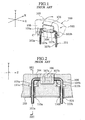
- FIG. 1 is a perspective view of a conventional headrest.
- an X-axis, a Y-axis and a Z-axis are defined in a direction from a rear surface toward a front surface of the headrest 100, a direction from a lower surface toward an upper surface of the headrest 100 and a direction from a left side surface toward a right side surface of the headrest 100, respectively.
- the X-axis, the Y-axis and the Z-axis are perpendicular to one another.
- a seat cushion and a seat back holding the seat cushion are not shown because these members are well known.
- the headrest 100 comprises a stay 101 and a headrest main body 102.
- the stay 101 is made of a metal pipe bent to be inverted U-shaped.
- the stay 101 is detachably engaged to the seat back by inserting stay main bodies 103a, 103b (vertical shafts) of the stay 101 into a pair of holders (not shown) which are fixedly installed to a top portion of the seat back (see Japanese Utility Model Publication No. H7-39607).
- the headrest main body 102 comprises a bracket 106, a pad 108 and a skin 109.
- the bracket 106 is rotatably supported to a connection section 104 (a horizontal shaft) of the stay 101 because a pair of bearings 107a, 107b installed on one side face of the bracket 106 hold the connection section 104.
- the pad 108 is made of a urethane foam material and covers the connection section 104, bend sections 105a, 105b of the stay 101 and the bracket 106.
- the skin 109 is made of a cloth etc. and covers the pad 108 so as to form the headrest main body 102.
- the headrest 100 is rotatably fixed to the seat back.
- FIG. 2 is a cross-sectional view of the conventional headrest sectioned along a Y-Z plane in FIG. 1.
- Recesses 110a, 110b are formed on a lower surface of the headrest main body 102 facing the seat back to introduce the stay 101 into an interior of the headrest main body 102.
- the connection section 104 and the bend sections 105a, 105b of the stay 101 are received in the interior of the headrest main body 102 through the recesses 110a, 110b.
- Two receiving ports are installed to receive the stay 101 in the interior of the headrest main body 102 from the recesses 110a, 110b.
- Patches 111a, 111b are installed on the receiving ports so as to prevent a urethane fluid or a semisolid pad existing in the interior of the headrest main body 102 from leaking to an outside of the headrest main body 102 at the time of forming the pad 108.
- the patches 111a, 111b are fixed to the stay main bodies 103a, 103b at the receiving ports.
- FIGS. 3A and 3B each is a cross-sectional view of the conventional headrest sectioned along a SE1-SE1 line in FIG. 2.
- FIG. 4 is a perspective view of the conventional headrest in which a C region of the headrest shown in FIG. 1 is enlarged.
- the stay main bodies 103a, 103b of the stay 101 are detachably engaged to the pair of holders that are fixedly installed to the top portion of the seat back.
- the headrest main body 102 is rotatably supported to the connection section 104 of the stay 101 via the bearings 107a, 107b of the bracket 106. Therefore, the headrest main body 102 may rotate around the connection section 104 in the direction of an arrow shown in FIG. 1.
- the headrest main body 102 does not smoothly rotate because the gaps between the patch 111a and the recess 110a and between the patch 111b and the recess 110b are filled with the pad 108.
- the length H of the bend sections 105a, 105b has a certain large value, flexibility of a form of the headrest main body 102 is reduced.
- An object of the present invention is to provide an automobile seat comprising a headrest which has high forming-flexibility by lessening the possibility that a urethane fluid or a semisolid pad leaks out of a receiving port for receiving a stay into an interior of the headrest at the time of forming a pad of the headrest and reducing a gap to be generated between a lower surface of the headrest and a top portion of the stay.
- the present invention provides an automobile seat comprising a headrest having a stay made of a pipe bent to be inverted U-shaped and detachably engaged to a top portion of a seat back and a headrest main body rotatably supported to a horizontal shaft of the stay, wherein a receiving port for introducing the horizontal shaft of the stay into an interior of the headrest main body is formed to the headrest main body so as to be located at a coaxial position with the horizontal shaft of the stay which is a rotational axial of the headrest main body.
- the receiving port for receiving the horizontal shaft of the stay is formed to the headrest main body so as to be located at a coaxial position with the horizontal shaft of the stay which is the rotational axial of the headrest main body, a urethane fluid or a semisolid pad is certainly prevented from leaking out even if the headrest main body is rotated by foaming pressure of the urethane fluid at the time of forming the pad.
- the headrest main body has a bracket for rotatably supporting the headrest main body to the horizontal shaft of the stay, a foaming material covering the horizontal shaft of the stay and the bracket, and a skin covering the foaming material, wherein the receiving port is formed on a side surface of a recess which is formed on the skin and receives a bend section of the stay.
- the receiving port is formed on the side surface of the recess which is formed on the skin and receives the bend section of the stay, it is not necessary to install patch on the receiving port and therefore, a distance between a bottom surface of the headrest main body and a connection section of the stay becomes small and flexibility of a form of the headrest main body is not reduced.
- a diameter of the receiving port is about half of a diameter of the horizontal shaft of the stay.
- the connection section of the stay is in close contact with the receiving port and therefore, the urethane fluid or the semisolid pad is certainly prevented from leaking out at the time of forming the pad.
- the side surface of the recess is made of an extensible material.
- connection section of the stay is in close contact with the receiving port and therefore, the urethane fluid or the semisolid pad is certainly prevented from leaking out at the time of forming the pad. It is further easy to engage the stay to the skin.
- an open length of the recess along an anteroposterior direction of the headrest main body is larger than a diameter of a vertical shaft of the stay.
- the headrest main body smoothly rotates around the horizontal shaft of the stay frontward or backward.
- FIG. 5 is a perspective view of a headrest according to the present embodiment.
- an X-axis, a Y-axis and a Z-axis are defined in a direction from a rear surface toward a front surface of the headrest 1, a direction from a lower surface toward an upper surface of the headrest 1 and a direction from a left side surface toward a right side surface of the headrest 1, respectively.
- the X-axis, the Y-axis and the Z-axis are perpendicular to one another.
- a seat cushion and a seat back holding the seat cushion are not shown because these members are well known.
- the headrest 1 comprises a stay 2 and a headrest main body 3.
- the stay 2 is made of a metal pipe bent to be inverted U-shaped.
- the stay 2 is detachably engaged to the seat back by inserting stay main bodies 4a, 4b (vertical shafts) of the stay 2 into a pair of holders which are fixedly installed to a top portion of the seat back.
- the headrest main body 3 comprises a bracket 13, a pad 6 and a skin 7.
- the bracket 13 is rotatably supported to a connection section 5 (a horizontal shaft) of the stay 2 because bearings 14a, 14b installed on the bracket 13 hold the connection section 5.
- the pad 6 is mad of a foaming material such as a urethane foam and covers the connection section 5 of the stay 2 and the bracket 13.
- the skin 7 is made of an extensible cloth and covers the pad 6 so as to form the headrest main body 3.
- the headrest 1 is rotatably fixed to the seat back.
- FIG. 6 is a cross-sectional view of the headrest according to the present embodiment sectioned along a Y-Z plane in FIG. 5.
- Recesses 9a, 9b are formed on a lower surface of the headrest main body 3 facing the seat back to introduce the stay 2 into an interior of the headrest main body 3.
- the connection section 5 and bend sections 8a, 8b of the stay 2 are respectively received in the interior of the headrest main body 3 and in interiors of the recesses 9a, 9b through the recesses 9a, 9b.
- Receiving ports 10a, 10b for receiving the stay 2 from the recesses 9a, 9b into the interior of the headrest main body 3 are respectively formed on side faces 12a, 12b of the recesses 9a, 9b which face each other.
- FIG. 7 is a perspective view of the recess 9a and the receiving port 10a from an arrow DB in FIG. 6.
- each diameter of the receiving ports 10a, 10b is about half of a diameter of connection section 5 of the stay 2.
- An open length L2 of the recesses 9a, 9b in the direction from the rear surface toward the front surface of the headrest, that is to say, along the X-axis, is slightly larger than a diameter of the stay main body 4 of the stay 2 so that the headrest main body 3 can smoothly rotate around the connection section 5 of the stay 2 within a predetermined rotational range.
- the skin 7 forms side faces of the recesses 9a, 9b and is sutured by engaging threads 11a, 11b on top portions of the recesses 9a, 9b.
- FIGS. 8A and 8B each is a cross-sectional view of the headrest according to the present invention sectioned along a SE2-SE2 line in FIG. 6.
- the stay main bodies 4a, 4b of the stay 2 are detachably engaged to the pair of holders that are fixedly installed to the top portion of the seat back.
- the headrest main body 3 is rotatably supported to the connection section 5 of the stay 2 via the bearings 14a, 14b of the bracket 13. Therefore, the headrest main body 3 may rotate around the connection section 5 in the direction of an arrow shown in FIG. 5.
- the receiving port 10a is always in close contact with the connection section 5 of the stay 2 because the receiving port 10a is formed at a coaxial position with the connection section 5 which is a rotational axis of the headrest main body 3. Therefore, the urethane fluid or a semisolid pad may not leak to the outside of the headrest main body 3. Also, as shown in FIG. 8A, in a case where the headrest main body 3 is rotated backward by foam pressure of a urethane fluid at the time of forming the pad 6, the receiving port 10a is always in close contact with the connection section 5 of the stay 2 because the receiving port 10a is formed at a coaxial position with the connection section 5 which is a rotational axis of the headrest main body 3. Therefore, the urethane fluid or a semisolid pad may not leak to the outside of the headrest main body 3. Also, as shown in FIG.
- the receiving port 10a in a case where the headrest main body 3 is rotated frontward by foam pressure of the urethane fluid at the time of forming the pad 6, the receiving port 10a is always in close contact with the connection section 5 of the stay 2 because the receiving port 10a is formed at the coaxial position with the connection section 5 which is a rotational axis of the headrest main body 3. Therefore, the urethane fluid or the semisolid pad may not leak to the outside of the headrest main body 3. It should be noted that this applies not only the receiving port 10a but also the receiving port 10b.
- the headrest 1 structured in this manner, it is not necessary to install patches on the receiving ports as with the conventional headrest because the receiving ports 10a, 10b are only formed on the side faces 12a, 12b of the recesses 9a, 9b. Further, if the headrest main body 3 is rotated frontward or backward by foaming pressure of the urethane fluid at the time of forming the pad 6, the urethane fluid or the semisolid pad is certainly prevented from leaking out because the receiving ports 10a, 10b are in close contact with the connection section 5 of the stay 2.
- the skin 7 forming the recesses 9a, 9b is made of the extensible cloth. Further, distances between the receiving port 10a and the connection section 5 and between the receiving port 10b and the connection section 5 become small and flexibility of a form of the headrest main body 3 is not reduced, because it is not necessary to install patches as with the conventional headrest.
- the headrest main body 3 rotates frontward or backward, a close-contact state of the stay 2 and the receiving ports 10a, 10b does not loosen because the receiving ports 10a, 10b are formed at the coaxial position with the connection section 5 which is the rotational axis of the headrest main body 3.
- the urethane fluid or the semisolid pad is certainly prevented from leaking out because the receiving ports for receiving the connection section of the stay are formed on the side faces of the recesses formed on the bottom surface of the headrest main body such that the receiving ports has a coaxial position with the connection section which is the rotational axis of the headrest main body. Further, a distance between the bottom surface of the headrest main body and the connection section of the stay becomes small and flexibility of a form of the headrest main body is not reduced because it is not necessary to install patches as with the conventional headrest.
- connection section of the stay is always in close contact with the receiving ports, because each diameter of the receiving ports is about half of a diameter of the connection section of the stay and the side faces of the recesses are made of the extensible cloth. Therefore, the urethane fluid or the semisolid pad is certainly prevented from leaking out.
Abstract
Description
- The present invention relates to an automobile seat, more specifically relates to a structure of a headrest with which the automobile seat is provided.
- For example, a conventional automobile seat is shown in FIGS. 1 to 4. FIG. 1 is a perspective view of a conventional headrest. As shown in FIG. 1, in a
headrest 100 in an original state, an X-axis, a Y-axis and a Z-axis are defined in a direction from a rear surface toward a front surface of theheadrest 100, a direction from a lower surface toward an upper surface of theheadrest 100 and a direction from a left side surface toward a right side surface of theheadrest 100, respectively. The X-axis, the Y-axis and the Z-axis are perpendicular to one another. A seat cushion and a seat back holding the seat cushion are not shown because these members are well known. - The
headrest 100 comprises astay 101 and a headrestmain body 102. Thestay 101 is made of a metal pipe bent to be inverted U-shaped. Thestay 101 is detachably engaged to the seat back by inserting staymain bodies stay 101 into a pair of holders (not shown) which are fixedly installed to a top portion of the seat back (see Japanese Utility Model Publication No. H7-39607). The headrestmain body 102 comprises abracket 106, apad 108 and askin 109. Thebracket 106 is rotatably supported to a connection section 104 (a horizontal shaft) of thestay 101 because a pair ofbearings bracket 106 hold theconnection section 104. Thepad 108 is made of a urethane foam material and covers theconnection section 104,bend sections stay 101 and thebracket 106. Theskin 109 is made of a cloth etc. and covers thepad 108 so as to form the headrestmain body 102. On the basis of the above structure, theheadrest 100 is rotatably fixed to the seat back. - FIG. 2 is a cross-sectional view of the conventional headrest sectioned along a Y-Z plane in FIG. 1.
Recesses main body 102 facing the seat back to introduce thestay 101 into an interior of the headrestmain body 102. Theconnection section 104 and thebend sections stay 101 are received in the interior of the headrestmain body 102 through therecesses stay 101 in the interior of the headrestmain body 102 from therecesses Patches main body 102 from leaking to an outside of the headrestmain body 102 at the time of forming thepad 108. Here, thepatches main bodies - FIGS. 3A and 3B each is a cross-sectional view of the conventional headrest sectioned along a SE1-SE1 line in FIG. 2. FIG. 4 is a perspective view of the conventional headrest in which a C region of the headrest shown in FIG. 1 is enlarged. The stay
main bodies stay 101 are detachably engaged to the pair of holders that are fixedly installed to the top portion of the seat back. The headrestmain body 102 is rotatably supported to theconnection section 104 of thestay 101 via thebearings bracket 106. Therefore, the headrestmain body 102 may rotate around theconnection section 104 in the direction of an arrow shown in FIG. 1. - As shown in FIG. 3A, in a case where the headrest
main body 102 is rotated backward by foam pressure of the urethane fluid at the time of forming thepad 108, a gap is generated between thepatch 111a and therecess 110a at a left side relative to a center axis M1 of therecess 110a because thepatch 111a is fixed to the staymain body 103a. Therefore, the urethane fluid or the semisolid pad may leak to the outside of the headrestmain body 102 from the gap. Also, as shown in FIG. 3B, in a case where the headrestmain body 102 is rotated frontward by foam pressure of the urethane fluid at the time of forming thepad 108, a gap is generated between thepatch 111a and therecess 110a at a right side relative to the center axis M1 of therecess 110a because thepatch 111a is fixed to the staymain body 103a. Therefore, the urethane fluid or the semisolid pad may leak to the outside of the headrestmain body 102 from the gap. It should be noted that this applies not only therecess 110a but also the recess 110b. - If the urethane fluid or the semisolid pad leaks out, an appearance of the headrest
main body 102 becomes ugly because thepad 108 is also generated at the outside of the headrestmain body 102, and it takes a lot of trouble because it is necessary to remove thepad 108 generated at the outside of the headrestmain body 102 by hand. Further, the headrestmain body 102 does not smoothly rotate because the gaps between thepatch 111a and therecess 110a and between thepatch 111b and therecess 110b are filled with thepad 108. - As shown in FIG.2, in order to dispose the
patch 111a between the receiving port of therecess 110a andconnection section 104 of thestay 101, it is necessary to increase a length H along the Y-axis of thebend section 105a to some extent. It should be noted that this applies not only the length H along the Y-axis of thebend section 105a but also that of thebend section 105b. However, if the length H of thebend sections recesses headrest 100 relative to the seat back. Thus, if the open length L1 of therecesses skin 109 increases with the increment of the open length L1. Thereby, if the headrestmain body 102 is rotated frontward or backward by foam pressure of the urethane fluid at the time of forming thepad 108, the urethane fluid or the semisolid pad may widely leak to the outside of the headrestmain body 102. - Further, if the length H of the
bend sections main body 102 is reduced. - The present invention is proposed in view of the above actual conditions. An object of the present invention is to provide an automobile seat comprising a headrest which has high forming-flexibility by lessening the possibility that a urethane fluid or a semisolid pad leaks out of a receiving port for receiving a stay into an interior of the headrest at the time of forming a pad of the headrest and reducing a gap to be generated between a lower surface of the headrest and a top portion of the stay.
- The present invention provides an automobile seat comprising a headrest having a stay made of a pipe bent to be inverted U-shaped and detachably engaged to a top portion of a seat back and a headrest main body rotatably supported to a horizontal shaft of the stay, wherein a receiving port for introducing the horizontal shaft of the stay into an interior of the headrest main body is formed to the headrest main body so as to be located at a coaxial position with the horizontal shaft of the stay which is a rotational axial of the headrest main body.
- According to this invention, since the receiving port for receiving the horizontal shaft of the stay is formed to the headrest main body so as to be located at a coaxial position with the horizontal shaft of the stay which is the rotational axial of the headrest main body, a urethane fluid or a semisolid pad is certainly prevented from leaking out even if the headrest main body is rotated by foaming pressure of the urethane fluid at the time of forming the pad.
- In a preferred embodiment of the present invention, the headrest main body has a bracket for rotatably supporting the headrest main body to the horizontal shaft of the stay, a foaming material covering the horizontal shaft of the stay and the bracket, and a skin covering the foaming material, wherein the receiving port is formed on a side surface of a recess which is formed on the skin and receives a bend section of the stay.
- According to this embodiment, since the receiving port is formed on the side surface of the recess which is formed on the skin and receives the bend section of the stay, it is not necessary to install patch on the receiving port and therefore, a distance between a bottom surface of the headrest main body and a connection section of the stay becomes small and flexibility of a form of the headrest main body is not reduced.
- In a preferred embodiment of the present invention, a diameter of the receiving port is about half of a diameter of the horizontal shaft of the stay.
- According to this embodiment, since the diameter of the receiving port is about half of the diameter of the connection section of the stay, the connection section of the stay is in close contact with the receiving port and therefore, the urethane fluid or the semisolid pad is certainly prevented from leaking out at the time of forming the pad.
- In a preferred embodiment of the present invention, the side surface of the recess is made of an extensible material.
- According to this embodiment, since the side surface of the recess is made of the extensible material, the connection section of the stay is in close contact with the receiving port and therefore, the urethane fluid or the semisolid pad is certainly prevented from leaking out at the time of forming the pad. It is further easy to engage the stay to the skin.
- In a preferred embodiment of the present invention, an open length of the recess along an anteroposterior direction of the headrest main body is larger than a diameter of a vertical shaft of the stay.
- According to this embodiment, since the open length of the recess along the anteroposterior direction of the headrest main body is larger than the diameter of the vertical shaft of the stay, the headrest main body smoothly rotates around the horizontal shaft of the stay frontward or backward.
-
- FIG. 1 is a perspective view of a conventional headrest.
- FIG. 2 is a cross-sectional view of the conventional headrest.
- FIGS. 3A and 3B are cross-sectional views sectioned along a SE1-SE1 line in FIG. 2 in which an action of the conventional headrest is explained.
- FIG. 4 is a perspective view in which a C region in FIG. 1 is enlarged.
- FIG. 5 is a perspective view of a headrest according to an embodiment of the present invention.
- FIG. 6 is an explanatory view of one portion of the headrest in FIG. 5 according to the embodiment of the present invention.
- FIG. 7 is a perspective view of the headrest from an arrow DB in FIG. 6 according to the embodiment of the present invention.
- FIGS. 8A and 8B are cross-sectional views sectioned along a SE2-SE2 line in FIG. 6 in which an action of the headrest according to the embodiment of the present invention is explained.
-
- Hereinafter, an embodiment of the present invention will be described with reference to drawings.
- FIG. 5 is a perspective view of a headrest according to the present embodiment. In a
headrest 1 in an original state shown in FIG. 5, an X-axis, a Y-axis and a Z-axis are defined in a direction from a rear surface toward a front surface of theheadrest 1, a direction from a lower surface toward an upper surface of theheadrest 1 and a direction from a left side surface toward a right side surface of theheadrest 1, respectively. The X-axis, the Y-axis and the Z-axis are perpendicular to one another. A seat cushion and a seat back holding the seat cushion are not shown because these members are well known. - The
headrest 1 comprises astay 2 and a headrestmain body 3. Thestay 2 is made of a metal pipe bent to be inverted U-shaped. Thestay 2 is detachably engaged to the seat back by inserting staymain bodies stay 2 into a pair of holders which are fixedly installed to a top portion of the seat back. The headrestmain body 3 comprises abracket 13, apad 6 and askin 7. Thebracket 13 is rotatably supported to a connection section 5 (a horizontal shaft) of thestay 2 becausebearings bracket 13 hold theconnection section 5. Thepad 6 is mad of a foaming material such as a urethane foam and covers theconnection section 5 of thestay 2 and thebracket 13. Theskin 7 is made of an extensible cloth and covers thepad 6 so as to form the headrestmain body 3. On the basis of the above structure, theheadrest 1 is rotatably fixed to the seat back. - FIG. 6 is a cross-sectional view of the headrest according to the present embodiment sectioned along a Y-Z plane in FIG. 5.
Recesses main body 3 facing the seat back to introduce thestay 2 into an interior of the headrestmain body 3. Theconnection section 5 and bendsections stay 2 are respectively received in the interior of the headrestmain body 3 and in interiors of therecesses recesses ports stay 2 from therecesses main body 3 are respectively formed on side faces 12a, 12b of therecesses - FIG. 7 is a perspective view of the
recess 9a and the receivingport 10a from an arrow DB in FIG. 6. In the present embodiment, each diameter of the receivingports connection section 5 of thestay 2. An open length L2 of therecesses stay 2 so that the headrestmain body 3 can smoothly rotate around theconnection section 5 of thestay 2 within a predetermined rotational range. Theskin 7 forms side faces of therecesses recesses - FIGS. 8A and 8B each is a cross-sectional view of the headrest according to the present invention sectioned along a SE2-SE2 line in FIG. 6. The stay
main bodies stay 2 are detachably engaged to the pair of holders that are fixedly installed to the top portion of the seat back. The headrestmain body 3 is rotatably supported to theconnection section 5 of thestay 2 via thebearings bracket 13. Therefore, the headrestmain body 3 may rotate around theconnection section 5 in the direction of an arrow shown in FIG. 5. - As shown in FIG. 8A, in a case where the headrest
main body 3 is rotated backward by foam pressure of a urethane fluid at the time of forming thepad 6, the receivingport 10a is always in close contact with theconnection section 5 of thestay 2 because the receivingport 10a is formed at a coaxial position with theconnection section 5 which is a rotational axis of the headrestmain body 3. Therefore, the urethane fluid or a semisolid pad may not leak to the outside of the headrestmain body 3. Also, as shown in FIG. 8B, in a case where the headrestmain body 3 is rotated frontward by foam pressure of the urethane fluid at the time of forming thepad 6, the receivingport 10a is always in close contact with theconnection section 5 of thestay 2 because the receivingport 10a is formed at the coaxial position with theconnection section 5 which is a rotational axis of the headrestmain body 3. Therefore, the urethane fluid or the semisolid pad may not leak to the outside of the headrestmain body 3. It should be noted that this applies not only the receivingport 10a but also the receivingport 10b. - In the
headrest 1 structured in this manner, it is not necessary to install patches on the receiving ports as with the conventional headrest because the receivingports recesses main body 3 is rotated frontward or backward by foaming pressure of the urethane fluid at the time of forming thepad 6, the urethane fluid or the semisolid pad is certainly prevented from leaking out because the receivingports connection section 5 of thestay 2. - Also, it is easy to engage the
stay 2 to theskin 7 because theskin 7 forming therecesses port 10a and theconnection section 5 and between the receivingport 10b and theconnection section 5 become small and flexibility of a form of the headrestmain body 3 is not reduced, because it is not necessary to install patches as with the conventional headrest. - Also, if the headrest
main body 3 rotates frontward or backward, a close-contact state of thestay 2 and the receivingports ports connection section 5 which is the rotational axis of the headrestmain body 3. - As described above, according to the automobile seat of the present invention, if the headrest main body is rotated by a foamed urethane fluid at the time of forming the pad, the urethane fluid or the semisolid pad is certainly prevented from leaking out because the receiving ports for receiving the connection section of the stay are formed on the side faces of the recesses formed on the bottom surface of the headrest main body such that the receiving ports has a coaxial position with the connection section which is the rotational axis of the headrest main body. Further, a distance between the bottom surface of the headrest main body and the connection section of the stay becomes small and flexibility of a form of the headrest main body is not reduced because it is not necessary to install patches as with the conventional headrest.
- Also, the connection section of the stay is always in close contact with the receiving ports, because each diameter of the receiving ports is about half of a diameter of the connection section of the stay and the side faces of the recesses are made of the extensible cloth. Therefore, the urethane fluid or the semisolid pad is certainly prevented from leaking out.
Claims (5)
- An automobile seat comprising:wherein a receiving port (10a, 10b) for introducing the horizontal shaft (5) of the stay (2) into an interior of the headrest main body (3) is formed to the headrest main body (3) so as to be located at a coaxial position with the horizontal shaft (5) of the stay (2) which is a rotational axial of the headrest main body (3).a headrest (1) having
a stay (2) made of a pipe bent to be inverted U-shaped and detachably engaged to a top portion of a seat back and
a headrest main body (3) rotatably supported to a horizontal shaft (5) of the stay (2): - The automobile seat according to claim 1, wherein the headrest main body (3) has a bracket (13) for rotatably supporting the headrest main body (3) to the horizontal shaft (5) of the stay (2), a foaming material (6) covering the horizontal shaft (5) of the stay (2) and the bracket (13), and a skin (7) covering the foaming material (6), wherein the receiving port (10a, 10b) is formed on a side surface (12a, 12b) of a recess (9a, 9b) which is formed on the skin (7) and receives a bend section (8a, 8b) of the stay (2).
- The automobile seat according to claim 2, wherein a diameter of the receiving port (10a, 10b) is about half of a diameter of the horizontal shaft (5) of the stay (2).
- The automobile seat according to claim 3, wherein the side surface (12a, 12b) of the recess (9a, 9b) is made of an extensible material.
- The automobile seat according to claim 2, wherein an open length (L2) of the recess (9a, 9b) along an anteroposterior direction of the headrest main body (3) is larger than a diameter of a vertical shaft (4a, 4b) of the stay (2).
Applications Claiming Priority (3)
| Application Number | Priority Date | Filing Date | Title |
|---|---|---|---|
| JP2002284312A JP4012028B2 (en) | 2002-09-27 | 2002-09-27 | Automotive seat |
| JP2002284312 | 2002-09-27 | ||
| PCT/JP2003/009452 WO2004028856A1 (en) | 2002-09-27 | 2003-07-25 | Automobile seat |
Publications (3)
| Publication Number | Publication Date |
|---|---|
| EP1550577A1 true EP1550577A1 (en) | 2005-07-06 |
| EP1550577A4 EP1550577A4 (en) | 2009-09-23 |
| EP1550577B1 EP1550577B1 (en) | 2013-09-04 |
Family
ID=32040583
Family Applications (1)
| Application Number | Title | Priority Date | Filing Date |
|---|---|---|---|
| EP03798369.9A Expired - Fee Related EP1550577B1 (en) | 2002-09-27 | 2003-07-25 | Automobile seat |
Country Status (6)
| Country | Link |
|---|---|
| US (1) | US7284795B2 (en) |
| EP (1) | EP1550577B1 (en) |
| JP (1) | JP4012028B2 (en) |
| CN (1) | CN100500475C (en) |
| AU (1) | AU2003248110A1 (en) |
| WO (1) | WO2004028856A1 (en) |
Families Citing this family (13)
| Publication number | Priority date | Publication date | Assignee | Title |
|---|---|---|---|---|
| US20080185900A1 (en) * | 2006-09-28 | 2008-08-07 | Lee Ellen Cheng-Ch | Use of renewable and biodegradable materials for automotive interiors |
| US20080164730A1 (en) * | 2007-01-05 | 2008-07-10 | Ford Global Technologies, Llc | Insert for vehicle seat head restraint |
| US8348338B2 (en) | 2007-09-10 | 2013-01-08 | Johnson Controls Technology Company | Electrical connection protection unit |
| DE102008029617B4 (en) * | 2008-06-23 | 2013-05-23 | Lear Corp. | Vehicle seat assembly with an energy absorption device |
| US20100078983A1 (en) * | 2008-10-01 | 2010-04-01 | Lear Corporation | Support member for vehicle seat head restraint |
| WO2010132548A2 (en) | 2009-05-13 | 2010-11-18 | Johnson Controls Technology Company | Rotating head rests |
| JP5781354B2 (en) * | 2011-03-31 | 2015-09-24 | テイ・エス テック株式会社 | Headrest |
| JP5913767B2 (en) * | 2012-05-25 | 2016-04-27 | 株式会社タチエス | Headrest interference prevention structure |
| DE102012012684B3 (en) * | 2012-06-27 | 2013-11-21 | Johnson Controls Gmbh | FASTENING ARRANGEMENT, HEADREST AND ASSEMBLY PROCEDURE |
| US9204724B2 (en) * | 2013-05-24 | 2015-12-08 | GM Global Technology Operations LLC | Seat assembly |
| JP6059086B2 (en) * | 2013-05-31 | 2017-01-11 | 株式会社タチエス | Headrest |
| US9511696B2 (en) | 2015-05-06 | 2016-12-06 | Daimay North America Automotive, Inc. | Rotatable headrest assembly |
| US11138220B2 (en) | 2016-11-27 | 2021-10-05 | Amazon Technologies, Inc. | Generating data transformation workflows |
Citations (2)
| Publication number | Priority date | Publication date | Assignee | Title |
|---|---|---|---|---|
| DE4337145A1 (en) * | 1992-11-06 | 1994-05-11 | Schmidt Gmbh R | Swivel mounted component for vehicle - has U=shaped or L=shaped bar inserted into bearing shell attached to shell of component housing |
| US5700057A (en) * | 1996-07-16 | 1997-12-23 | Gestind-M.B. "Manifattura Di Brusolo" S.P.A. | Headrest for motor vehicle seats and a method for its manufacturing |
Family Cites Families (11)
| Publication number | Priority date | Publication date | Assignee | Title |
|---|---|---|---|---|
| JPS6484233A (en) | 1987-09-28 | 1989-03-29 | Canon Kk | Optical system moving device for camera or the like |
| JPH0184233U (en) * | 1987-11-26 | 1989-06-05 | ||
| JPH0686608A (en) | 1992-09-08 | 1994-03-29 | Iseki & Co Ltd | Threshing and culm-discharging machine on combine |
| JP2574304Y2 (en) * | 1993-06-02 | 1998-06-11 | 高島屋日発工業株式会社 | Headrest |
| JP2664857B2 (en) | 1993-07-30 | 1997-10-22 | 住友ゴム工業株式会社 | Thread wound golf ball |
| JPH0739607U (en) * | 1993-12-30 | 1995-07-18 | 株式会社タチエス | Headrest front-back position adjustment device |
| JP3694936B2 (en) * | 1995-04-20 | 2005-09-14 | トヨタ紡織株式会社 | Retractable headrest |
| DE19618700C2 (en) * | 1995-05-12 | 2002-12-05 | Aisin Seiki | Seat headrest for a vehicle |
| JP3997565B2 (en) | 1997-06-20 | 2007-10-24 | トヨタ紡織株式会社 | Headrest device for vehicle seat |
| US6183045B1 (en) * | 1998-06-03 | 2001-02-06 | Magna Interior Systems Inc. | Method of manufacturing an interior automotive component and components made therefrom |
| JP2002165670A (en) * | 2000-11-30 | 2002-06-11 | Tachi S Co Ltd | Headrest |
-
2002
- 2002-09-27 JP JP2002284312A patent/JP4012028B2/en not_active Expired - Fee Related
-
2003
- 2003-07-25 EP EP03798369.9A patent/EP1550577B1/en not_active Expired - Fee Related
- 2003-07-25 CN CNB038227959A patent/CN100500475C/en not_active Expired - Fee Related
- 2003-07-25 WO PCT/JP2003/009452 patent/WO2004028856A1/en active Application Filing
- 2003-07-25 AU AU2003248110A patent/AU2003248110A1/en not_active Abandoned
- 2003-07-25 US US10/529,274 patent/US7284795B2/en not_active Expired - Fee Related
Patent Citations (2)
| Publication number | Priority date | Publication date | Assignee | Title |
|---|---|---|---|---|
| DE4337145A1 (en) * | 1992-11-06 | 1994-05-11 | Schmidt Gmbh R | Swivel mounted component for vehicle - has U=shaped or L=shaped bar inserted into bearing shell attached to shell of component housing |
| US5700057A (en) * | 1996-07-16 | 1997-12-23 | Gestind-M.B. "Manifattura Di Brusolo" S.P.A. | Headrest for motor vehicle seats and a method for its manufacturing |
Non-Patent Citations (1)
| Title |
|---|
| See also references of WO2004028856A1 * |
Also Published As
| Publication number | Publication date |
|---|---|
| EP1550577A4 (en) | 2009-09-23 |
| JP4012028B2 (en) | 2007-11-21 |
| US20060097561A1 (en) | 2006-05-11 |
| CN1701001A (en) | 2005-11-23 |
| JP2004114959A (en) | 2004-04-15 |
| US7284795B2 (en) | 2007-10-23 |
| WO2004028856A1 (en) | 2004-04-08 |
| CN100500475C (en) | 2009-06-17 |
| EP1550577B1 (en) | 2013-09-04 |
| AU2003248110A1 (en) | 2004-04-19 |
Similar Documents
| Publication | Publication Date | Title |
|---|---|---|
| EP1550577A1 (en) | Automobile seat | |
| ES2150841A1 (en) | Vehicle seat arrangement | |
| JP2005280693A (en) | Vehicle body structure | |
| JPH0986246A (en) | Rear seat device for vehicle | |
| FR2971756A1 (en) | SECURITY BELT REEL SUPPORT. | |
| TW200621550A (en) | Outer mirror with front view arrangement | |
| JP4075452B2 (en) | Headrest device | |
| KR20070110356A (en) | Form part for a vehicle, in particular for a seat and provided, in particular, with sensor means | |
| JP2016132298A (en) | Headrest | |
| US5042877A (en) | Arrangement of arm rest in automotive seat | |
| KR200256470Y1 (en) | headrest of clinging monitor | |
| JP2005299085A (en) | Door outside handle | |
| CN102837627A (en) | Headrest support structure | |
| CN112389555A (en) | Guide wheel mechanism, drive device, and excavator | |
| JP3713936B2 (en) | Side panel mounting structure | |
| JP6016194B2 (en) | Vehicle seat | |
| CN214929188U (en) | Car seat handrail with higher structural strength | |
| FR3069817A1 (en) | SYSTEM AND METHOD FOR ATTACHING A FAN TO A MOTOR VEHICLE SEAT SUSPENSION TABLE. | |
| JP7443886B2 (en) | Mirror mounting structure | |
| JPH08169266A (en) | Vehicular seat hinge | |
| JP2006167251A (en) | Seat back for vehicle | |
| JPH055084Y2 (en) | ||
| CA2747445A1 (en) | Method of designing a driver's compartment | |
| FR3134045A1 (en) | Seat assembly comprising a first padding and a second padding, and system for fixing the cover of the first padding | |
| JP4384517B2 (en) | Vehicle seat |
Legal Events
| Date | Code | Title | Description |
|---|---|---|---|
| PUAI | Public reference made under article 153(3) epc to a published international application that has entered the european phase |
Free format text: ORIGINAL CODE: 0009012 |
|
| 17P | Request for examination filed |
Effective date: 20050422 |
|
| AK | Designated contracting states |
Kind code of ref document: A1 Designated state(s): AT BE BG CH CY CZ DE DK EE ES FI FR GB GR HU IE IT LI LU MC NL PT RO SE SI SK TR |
|
| AX | Request for extension of the european patent |
Extension state: AL LT LV MK |
|
| DAX | Request for extension of the european patent (deleted) | ||
| RBV | Designated contracting states (corrected) |
Designated state(s): DE FR GB |
|
| A4 | Supplementary search report drawn up and despatched |
Effective date: 20090821 |
|
| 17Q | First examination report despatched |
Effective date: 20100326 |
|
| GRAP | Despatch of communication of intention to grant a patent |
Free format text: ORIGINAL CODE: EPIDOSNIGR1 |
|
| GRAS | Grant fee paid |
Free format text: ORIGINAL CODE: EPIDOSNIGR3 |
|
| GRAA | (expected) grant |
Free format text: ORIGINAL CODE: 0009210 |
|
| AK | Designated contracting states |
Kind code of ref document: B1 Designated state(s): DE FR GB |
|
| REG | Reference to a national code |
Ref country code: GB Ref legal event code: FG4D |
|
| REG | Reference to a national code |
Ref country code: DE Ref legal event code: R096 Ref document number: 60344874 Country of ref document: DE Effective date: 20131031 |
|
| REG | Reference to a national code |
Ref country code: DE Ref legal event code: R097 Ref document number: 60344874 Country of ref document: DE |
|
| PLBE | No opposition filed within time limit |
Free format text: ORIGINAL CODE: 0009261 |
|
| STAA | Information on the status of an ep patent application or granted ep patent |
Free format text: STATUS: NO OPPOSITION FILED WITHIN TIME LIMIT |
|
| 26N | No opposition filed |
Effective date: 20140605 |
|
| REG | Reference to a national code |
Ref country code: DE Ref legal event code: R097 Ref document number: 60344874 Country of ref document: DE Effective date: 20140605 |
|
| PGFP | Annual fee paid to national office [announced via postgrant information from national office to epo] |
Ref country code: DE Payment date: 20140721 Year of fee payment: 12 |
|
| PGFP | Annual fee paid to national office [announced via postgrant information from national office to epo] |
Ref country code: FR Payment date: 20140721 Year of fee payment: 12 |
|
| GBPC | Gb: european patent ceased through non-payment of renewal fee |
Effective date: 20140725 |
|
| PG25 | Lapsed in a contracting state [announced via postgrant information from national office to epo] |
Ref country code: GB Free format text: LAPSE BECAUSE OF NON-PAYMENT OF DUE FEES Effective date: 20140725 |
|
| REG | Reference to a national code |
Ref country code: DE Ref legal event code: R119 Ref document number: 60344874 Country of ref document: DE |
|
| PG25 | Lapsed in a contracting state [announced via postgrant information from national office to epo] |
Ref country code: DE Free format text: LAPSE BECAUSE OF NON-PAYMENT OF DUE FEES Effective date: 20160202 |
|
| REG | Reference to a national code |
Ref country code: FR Ref legal event code: ST Effective date: 20160331 |
|
| PG25 | Lapsed in a contracting state [announced via postgrant information from national office to epo] |
Ref country code: FR Free format text: LAPSE BECAUSE OF NON-PAYMENT OF DUE FEES Effective date: 20150731 |