EP1550576A2 - Vehicle occupant sensing system - Google Patents
Vehicle occupant sensing system Download PDFInfo
- Publication number
- EP1550576A2 EP1550576A2 EP04257507A EP04257507A EP1550576A2 EP 1550576 A2 EP1550576 A2 EP 1550576A2 EP 04257507 A EP04257507 A EP 04257507A EP 04257507 A EP04257507 A EP 04257507A EP 1550576 A2 EP1550576 A2 EP 1550576A2
- Authority
- EP
- European Patent Office
- Prior art keywords
- electrode
- load
- reading
- electrode connection
- parameter
- Prior art date
- Legal status (The legal status is an assumption and is not a legal conclusion. Google has not performed a legal analysis and makes no representation as to the accuracy of the status listed.)
- Granted
Links
- 238000012360 testing method Methods 0.000 claims description 29
- 238000000034 method Methods 0.000 claims description 9
- 230000004913 activation Effects 0.000 claims description 4
- 230000007246 mechanism Effects 0.000 abstract description 2
- 238000001514 detection method Methods 0.000 description 13
- 238000005259 measurement Methods 0.000 description 13
- 238000010586 diagram Methods 0.000 description 8
- 238000006243 chemical reaction Methods 0.000 description 5
- PXHVJJICTQNCMI-UHFFFAOYSA-N Nickel Chemical compound [Ni] PXHVJJICTQNCMI-UHFFFAOYSA-N 0.000 description 4
- 230000004044 response Effects 0.000 description 4
- 230000003321 amplification Effects 0.000 description 3
- 238000013461 design Methods 0.000 description 3
- 238000003199 nucleic acid amplification method Methods 0.000 description 3
- RYGMFSIKBFXOCR-UHFFFAOYSA-N Copper Chemical compound [Cu] RYGMFSIKBFXOCR-UHFFFAOYSA-N 0.000 description 2
- 238000013459 approach Methods 0.000 description 2
- 229910052802 copper Inorganic materials 0.000 description 2
- 239000010949 copper Substances 0.000 description 2
- 230000006870 function Effects 0.000 description 2
- 229910052759 nickel Inorganic materials 0.000 description 2
- 230000003287 optical effect Effects 0.000 description 2
- 238000004458 analytical method Methods 0.000 description 1
- 230000008859 change Effects 0.000 description 1
- 239000011248 coating agent Substances 0.000 description 1
- 238000000576 coating method Methods 0.000 description 1
- 238000005260 corrosion Methods 0.000 description 1
- 230000007797 corrosion Effects 0.000 description 1
- 230000000694 effects Effects 0.000 description 1
- 230000005684 electric field Effects 0.000 description 1
- 239000000835 fiber Substances 0.000 description 1
- 238000009472 formulation Methods 0.000 description 1
- 108010084652 homeobox protein PITX1 Proteins 0.000 description 1
- 230000002452 interceptive effect Effects 0.000 description 1
- 239000011159 matrix material Substances 0.000 description 1
- 239000002184 metal Substances 0.000 description 1
- 229910052751 metal Inorganic materials 0.000 description 1
- 239000000203 mixture Substances 0.000 description 1
- 238000010606 normalization Methods 0.000 description 1
- 230000010355 oscillation Effects 0.000 description 1
- 239000003973 paint Substances 0.000 description 1
- 229920000728 polyester Polymers 0.000 description 1
- 238000012545 processing Methods 0.000 description 1
- 230000003362 replicative effect Effects 0.000 description 1
- 238000000926 separation method Methods 0.000 description 1
- 238000009958 sewing Methods 0.000 description 1
Images


Classifications
-
- B—PERFORMING OPERATIONS; TRANSPORTING
- B60—VEHICLES IN GENERAL
- B60R—VEHICLES, VEHICLE FITTINGS, OR VEHICLE PARTS, NOT OTHERWISE PROVIDED FOR
- B60R21/00—Arrangements or fittings on vehicles for protecting or preventing injuries to occupants or pedestrians in case of accidents or other traffic risks
- B60R21/01—Electrical circuits for triggering passive safety arrangements, e.g. airbags, safety belt tighteners, in case of vehicle accidents or impending vehicle accidents
- B60R21/015—Electrical circuits for triggering passive safety arrangements, e.g. airbags, safety belt tighteners, in case of vehicle accidents or impending vehicle accidents including means for detecting the presence or position of passengers, passenger seats or child seats, and the related safety parameters therefor, e.g. speed or timing of airbag inflation in relation to occupant position or seat belt use
- B60R21/01512—Passenger detection systems
- B60R21/0153—Passenger detection systems using field detection presence sensors
- B60R21/01532—Passenger detection systems using field detection presence sensors using electric or capacitive field sensors
-
- B—PERFORMING OPERATIONS; TRANSPORTING
- B60—VEHICLES IN GENERAL
- B60N—SEATS SPECIALLY ADAPTED FOR VEHICLES; VEHICLE PASSENGER ACCOMMODATION NOT OTHERWISE PROVIDED FOR
- B60N2/00—Seats specially adapted for vehicles; Arrangement or mounting of seats in vehicles
- B60N2/002—Seats provided with an occupancy detection means mounted therein or thereon
- B60N2/0021—Seats provided with an occupancy detection means mounted therein or thereon characterised by the type of sensor or measurement
- B60N2/0035—Seats provided with an occupancy detection means mounted therein or thereon characterised by the type of sensor or measurement characterised by the sensor data transmission, e.g. wired connections or wireless transmitters therefor; characterised by the sensor data processing, e.g. seat sensor signal amplification or electric circuits for providing seat sensor information
-
- B—PERFORMING OPERATIONS; TRANSPORTING
- B60—VEHICLES IN GENERAL
- B60R—VEHICLES, VEHICLE FITTINGS, OR VEHICLE PARTS, NOT OTHERWISE PROVIDED FOR
- B60R21/00—Arrangements or fittings on vehicles for protecting or preventing injuries to occupants or pedestrians in case of accidents or other traffic risks
- B60R21/01—Electrical circuits for triggering passive safety arrangements, e.g. airbags, safety belt tighteners, in case of vehicle accidents or impending vehicle accidents
- B60R21/015—Electrical circuits for triggering passive safety arrangements, e.g. airbags, safety belt tighteners, in case of vehicle accidents or impending vehicle accidents including means for detecting the presence or position of passengers, passenger seats or child seats, and the related safety parameters therefor, e.g. speed or timing of airbag inflation in relation to occupant position or seat belt use
- B60R21/01512—Passenger detection systems
- B60R21/0153—Passenger detection systems using field detection presence sensors
- B60R21/0154—Passenger detection systems using field detection presence sensors in combination with seat heating
-
- B—PERFORMING OPERATIONS; TRANSPORTING
- B60—VEHICLES IN GENERAL
- B60R—VEHICLES, VEHICLE FITTINGS, OR VEHICLE PARTS, NOT OTHERWISE PROVIDED FOR
- B60R21/00—Arrangements or fittings on vehicles for protecting or preventing injuries to occupants or pedestrians in case of accidents or other traffic risks
- B60R21/01—Electrical circuits for triggering passive safety arrangements, e.g. airbags, safety belt tighteners, in case of vehicle accidents or impending vehicle accidents
- B60R21/015—Electrical circuits for triggering passive safety arrangements, e.g. airbags, safety belt tighteners, in case of vehicle accidents or impending vehicle accidents including means for detecting the presence or position of passengers, passenger seats or child seats, and the related safety parameters therefor, e.g. speed or timing of airbag inflation in relation to occupant position or seat belt use
- B60R21/01556—Child-seat detection systems
-
- B—PERFORMING OPERATIONS; TRANSPORTING
- B60—VEHICLES IN GENERAL
- B60N—SEATS SPECIALLY ADAPTED FOR VEHICLES; VEHICLE PASSENGER ACCOMMODATION NOT OTHERWISE PROVIDED FOR
- B60N2/00—Seats specially adapted for vehicles; Arrangement or mounting of seats in vehicles
- B60N2/24—Seats specially adapted for vehicles; Arrangement or mounting of seats in vehicles for particular purposes or particular vehicles
- B60N2/26—Seats specially adapted for vehicles; Arrangement or mounting of seats in vehicles for particular purposes or particular vehicles for children
- B60N2/28—Seats readily mountable on, and dismountable from, existing seats or other parts of the vehicle
-
- B—PERFORMING OPERATIONS; TRANSPORTING
- B60—VEHICLES IN GENERAL
- B60N—SEATS SPECIALLY ADAPTED FOR VEHICLES; VEHICLE PASSENGER ACCOMMODATION NOT OTHERWISE PROVIDED FOR
- B60N2220/00—Computerised treatment of data for controlling of seats
- B60N2220/10—Computerised treatment of data for controlling of seats using a database
Definitions
- the present invention relates to vehicle occupant sensing. More specifically, the present invention relates to automatic detection of the presence of an occupant on a vehicle seat and occupant characteristics such as age or facing, with a special focus on detecting children in child safety restraint devices, such as safety seats.
- Child safety has always been an important societal focus. In recent years, for example, great progress has been made in the design of child safety seats for automobiles. In fact, in many instances, hospitals require new parents to have a properly configured child safety seat waiting in their car before they can even take their own child home.
- the child safety seat does not protect the child from all dangers, however. In particular, when young children are left unattended in an automobile, the consequences can be tragic. Each year, multiple children suffocate because they were left unintentionally in the back seat of a car, minivan, or other vehicle.
- weight sensors may incorrectly detect or classify unusually light or heavy children.
- optical sensors are typically expensive and require complex optical processing equipment.
- the occupant sensing systems described below are adept at determining whether an occupied or unoccupied child restraint device (e.g., a child safety seat) is present on a vehicle seat.
- the occupant sensors may determine additional characteristics about the restraint device, including its facing (e.g., either front facing or rear facing), and an approximate age of a child occupying the restraint device.
- the sensors determine characteristics of occupants free of any child safety seat.
- the sensing systems may include a first electrode connection and a second electrode connection.
- a circuit parameter sensor operates in conjunction with a controller to provide a first parameter reading for the first electrode connection, and a second parameter reading for the second electrode connection.
- the controller determines occupant presence based, for example, on a ratio or product of the first and second parameter readings and a pre-selected threshold.
- three or more electrodes are positioned in a seat.
- One of the electrodes is non-switchably connected to virtual or relative ground.
- the remaining electrodes are used to sense an occupant or characteristics of the occupant.
- the discussion below presents exemplary implementations of an occupant sensing system.
- the discussion is therefore not limiting, but explanatory in nature.
- the occupant sensing systems generally incorporate capacitive arrangements of multiple electrodes driven by a signal source, with a controller that interprets resultant loading or received current readings.
- the sensing systems may employ the circuits and techniques described in U.S. Pat. No. 6,329,913, U.S. Pat. No. 6,329,914, or U.S. Pat. Pub. No. 2003-0090376 (App. Serial No. 10/033,585).
- the '913 patent, '914 patent, and the '585 application are incorporated herein by reference in their entireties.
- Sensing systems using capacitive bridges, phase detection, capacitance measurement, frequency changes or other techniques for detection with transmitted signals may be used.
- FIG. 1 that figure shows a vehicle seat 100.
- Figure 1 illustrates the vehicle seat 100 as a longer bench seat (e.g., particularly suited for a minivan), the vehicle seat 100 may be a shorter seat, including a front or rear single passenger seat.
- the seat 100 includes a seat base 102, a seat back 104, and a seat bite 106 where the seat base 102 meets the seat back 104.
- Ground electrodes 108 and 110 are present inside or on the seat 100. As shown, the ground electrodes 108 and 110 are placed in the seat base 102, but may be positioned in the seat back 104 in other embodiments. Furthermore, signal electrodes 112, 114, 116, 118, 120, and 122 are also present in pairs in the seat 100. The electrode pairs are disposed across the seating positions 124, 126, and 128. The seating positions 124-128 may correspond, for example, to lawful placement positions for a child safety seat on the seat 100. In other embodiments, two or more electrodes in the seat back extend across multiple seating positions.
- any of the electrodes 112-122 may be separated by at least a vehicle cabin feature distance.
- the electrodes 112-122 may be separated by the largest dimension of a seat belt buckle, in order to prevent the seat belt buckle from shorting the two elements or interfering with electrical operation of the signal electrodes 112-122.
- Other cabin features may also be taken into consideration, for example, the largest dimension of a radio or DVD remote control, or the like, may influence the electrode 112-122 separation.
- the upper and lower electrodes are separated by approximately 25 to 50 mm.
- the ground plane 108 may span multiple sensing positions, a separate ground plane may support any given sensing position.
- the electrode pair 120 and 122 operate in conjunction with the separate ground plane 110 to form a third sensing position for the seat 100.
- the ground planes 108, 110 are connected to the vehicle chassis ground 130. While the ground planes 108, 110 may be connected permanently through non-switchable connections (as shown in Figure 1) to the chassis ground, the ground planes 108, 110 may also be connected to a switch matrix that allows them to disconnect from the chassis ground and take the role of a signal electrode. Note that the ground planes 108, 110 or signal electrodes 112-122 may be slotted, cut, or otherwise shaped to impart additional flexibility or breathability for the seat 100.
- the ground planes 108, 110 or signal electrodes 112-122 may be formed, for example, from a conductively coated sheet of polyester disposed in the seat 100.
- the conductive coating may include a layer of Nickel, a layer of Copper, and a layer of Nickel to protect the copper from corrosion.
- conductive paint, tape, or sewn metal fibers may form the ground planes 108, 110 and signal electrodes 112-122.
- the size, orientation, and relative position of the ground planes 108, 110 and signal electrodes 112-122 may vary according to the design of the seat 100, or in response to empirical studies of occupied and unoccupied child restraint devices. Consequently, in one implementation, the signal electrodes 112-122 are shaped to fit in the sewing line groves 132 of the seat 100.
- the electrode 122 may be 280 mm wide and 220 mm high, and may be located 140 mm above the seat bite 106.
- the electrode 120 may then be 280 mm wide and 200 mm high, and may be located 30 mm above the electrode 122.
- the ground plane 110 may be 450 mm wide and 320 mm long, and may be located 140 mm in front of the seat bite 106.
- Other sizes, shapes, positions, and orientations for the electrodes 112-122 are also suitable however.
- FIG. 2 that figure shows a block diagram of an occupant sensing system 200 that may be part of a larger vehicle electronics system.
- the occupant sensing system 200 includes a signal source 202 that presents a signal on a detection signal output 204 to a load sensor 206.
- the load sensor 206 connects to a switching circuit 208 that connects or disconnects the detection signal output 204 (and therefore the signal source 202) to one or more electrode connections E1, E2, E3, E4, E5, and E6.
- the switching circuit 208 connects the electrode connections E1-E6 to the current-to-voltage conversion circuit 210. Both the conversion circuit 210 and the load sensor 206 connect to the detecting circuit 212.
- the load sensor 206 and/or the converting circuit 210 may generally be considered circuit parameter sensors. Accordingly, in one implementation, the load sensor 206 provides a voltage or current output indicative of load current flowing from the signal source 202 through the electrode connections E1 - E6. Similarly, the converting circuit 210 provides a voltage or current output indicative of return current arriving through the electrode connections E1 - E6, regardless of origin. While the discussion below proceeds with regard to current and voltage sensing, the sensing system 200 may alternatively or additionally employ a wide variety of circuit parameter sensors that measure, as examples, capacitance, phase, frequency, or Q, or that measure combinations of such circuit parameters.
- the detecting circuit 212 connects to an amplification circuit 214 connected to the controller 216.
- the controller 216 applies controls signals to the offset converting circuit 218, and to the air bag device 220 or a warning device.
- the controller 216 may operate under control of an occupancy sensing program 222 stored in a memory 224. Consequently, the controller 216 may operate as explained below to determine whether any of the seating positions 124-128 are occupied and, optionally, one or more characteristics of the occupant.
- Example implementations for the sensing system 200 are described in detail below, and in conjunction with Figure 3. Other circuits may be substituted, or circuit parameters modified, however, depending on the particular implementation desired.
- the signal source 202 may be a 100-120 kHz oscillator that outputs a 10-12 volt signal on the detection signal output 204.
- the switching circuit 208 may incorporate a multiplexer, switches or other devices that selectively connect the electrodes E1-E6 to the signal source 202.
- the conversion circuit 210 includes a resistor network and generates voltage signals indicative of the current returning from or transmitting from the electrode connections E1-E6 through the switching circuit 208.
- the conversion circuit 210 may also amplify the voltage signals before outputting them to the detection circuit 212.
- the detection circuit 212 may include a demodulation circuit including a band pass filter that eliminates noise coupled to an AC-DC converter to provide a DC signal output to the converting circuit 210.
- the controller 216 may be an ASIC, processor, digital signal processor or other circuitry for evaluating the signals obtained from the amplifying circuit 214.
- the controller 216 may be a PD78052CG(A) microprocessor manufactured by NEC Corporation of Japan that substitutes its own AC-DC conversion circuitry for that noted above in the detection circuit 212.
- the controller 216 after evaluating the signals, may set an occupancy indicator that specifies whether a particular seating position is occupied.
- the occupancy indicator may be an internal register or memory setting, or may be an external indicator such as a warning lamp, dashboard indicator, speaker alarm, voice prompt, or another indicator.
- Figure 3 is a circuit diagram 300 that shows the occupant sensing system 200 in additional detail. While four channels are shown (E1 - E4), the circuitry shown in Figure 3 may be extended to more channels (e.g., 6 channels E1 - E6) by replicating the sensing and detection circuitry described below. In other implementations, the sensing system 200 may use fewer channels, such as where connected with a single passenger seat, or on a larger multiple passenger seat for which fewer sensing positions are desirable. Note also that the sensing system 200 may determine occupant presence across multiple physically separate seats. The circuitry 300 connects to the six electrodes 112-122 to provide occupancy sensing across multiple positions in the seat 100. The controller 216 may then scan across the seat sequentially or at random to determine whether the sensors for any seating position 124-128 indicate that an occupant is present or a characteristic of the occupant.
- the amplification circuit 214 includes a relatively low gain (e.g., a gain of approximately 1) amplifier 302 and a relatively high gain (e.g., a gain of approximately 100) amplifier 304.
- An analog switch 306 selectively connects the outputs of the low gain amplifier 302 or the high gain amplifier 304 to the controller 216 through the switching elements 308 and 310 as directed by the controller 216.
- the load sensor 206 may be implemented as an impedance/resistance element 312 and an amplifier 314 connected between the signal source 202 and the switching circuit 208.
- the load sensor 206 thereby provides a voltage signal to the detection circuit 212 that indicates the amount of current flowing to the switching circuit 208 (and thus to one of the electrodes 112-122).
- the switching circuit 208 includes switching elements 324, 326, 328, and 330 and switching elements 332, 334, 336, and 338.
- the switching elements 324-330 selectively connect, in response to a control signal 320 from the controller 216, an electrode connection E1 - E4 to the signal source 202.
- the signal source 202 thereby drives the electrode connected to the electrode connection E1 - E4.
- the load sensor 206 responsively measures the load current flowing to the electrode, with respect to the ground planes 108 - 110 and other grounding provided through any occupant to the vehicle.
- the controller 216 may open or close the switches 332 - 338 in order to obtain measurements of return currents present in the remaining electrodes.
- the load sensor 206, the converting circuit 210, or other circuit parameter sensors measure parameters associated with electrodes different from the electrode used to transmit.
- the converting circuit 210 may include an impedance/resistance element 318 that converts current flowing in the receiver electrodes to voltage signals, and an amplifier 316 that amplifies the converted voltage signals.
- the impedance/resistance elements 318 shunts high frequency noise from the input of the amplifier 316 to ground.
- the detecting circuit 212 may include an impedance or resistance element and a differential amplifier (or other amplifier) whose output is coupled to the controller 216 through the amplifier circuit 214.
- a differential amplifier or other amplifier
- One such impedance/resistance element may be connected between the output of an amplification control circuit and the electrode connections E1 - E4.
- the differential amplifier may be connected across the impedance/resistance element to generate a current signal based on the voltage differential across the impedance/resistance element.
- the current differential amplifier compares the voltage level of the oscillation circuit output signal with the voltage level generated on an electrode, and generates a current signal representative of the difference.
- the detecting circuit 212 thereby receives the output signal from the load sensor 206 as well as the signals from the receiving electrodes and couples them to the high gain amplifier 304 and the low gain amplifier 302.
- the high gain amplified outputs couple to the switches 308, while the low gain amplified outputs couple to the switches 310.
- the analog switch 306 couples either the high gain or low gain output to input pins on the controller 216.
- FIG. 4 shows a sensor configuration 400 adapted to determine whether the seat 100 is occupied. More specifically the sensor configuration 400 may determine whether an occupied or unoccupied child safety seat is present.
- the child safety seat may be a rear facing child safety seat 402 or a front facing child safety seat 404.
- the seat 100 includes an electrode pair 112, 114, and a ground plane 108.
- the first electrode 112 is disposed in the seat 100 as an upper body electrode.
- the upper body electrode is a head electrode disposed at a pre-selected head height, Hh, for an occupied child safety seat.
- the second electrode 114 is disposed in the seat 100 as a lower body electrode.
- the lower body electrode is a foot electrode disposed at a pre-selected foot height, Fh, for an occupied child safety seat.
- the electrode heights may be empirically determined through examination, measurement, and testing of multiple models of child safety seats, in conjunction with statistical data (e.g., dimensional measurements) of young children that occupy such safety seats.
- the height Fh is approximately 140 mm above the seat bite 106
- the height Hh is approximately 390 mm above the seat bite 106.
- the head electrode 112 may be connected to the sensing system 200 through an electrode connection E1-E6.
- the electrode connection E1 may serve as a seat back head electrode connection.
- the electrode connection E2 may serve as a seat back foot electrode connection.
- the head electrode 112 and foot electrode 114 form an electric field sensing circuit.
- the controller 216 may determine occupant presence or absence in many ways. For example, the controller 216 may measure the loading current, HL, to the head electrode 112 and the loading current, FL, to the foot electrode 112. Then, the controller may apply an occupancy test according to HL ⁇ T1 and FL ⁇ T2, where T1 and T2 are pre-determined thresholds based on prior studies of occupied and unoccupied child safety seats. If HL ⁇ T1 and FL ⁇ T2, then the controller 216 may determine that no occupant is present on the seat 100. In one implementation, T1 and T2 may be approximately 6 bits, although other threshold settings may also be suitable based on the particular design.
- the controller 216 may apply additional occupancy tests. For example, the controller 216 may next determine whether FL - HL ⁇ T3 and (FUHL) ⁇ T4, where T3 and the ratio threshold T4 are pre-determined thresholds based on prior studies of occupied and unoccupied child safety seats. Thus, when the foot electrode load current is greater than the head electrode load current (e.g., when the child's feet are closer to the foot electrode 114 than the head is to the heat electrode 112), and when their ratio is less than a threshold, the controller 216 may determine that a rear facing child safety seat 402 is present. For the purposes of this occupancy test, T3 may be approximately zero bits, while T4 may be approximately 1. Other thresholds may be employed, however.
- the controller 216 may determine whether FL - HL > T5 and (HUFL) > T6, where T5 and the ratio threshold T6 are pre-determined thresholds based on prior studies of occupied and unoccupied child safety seats. The test succeeds when an occupied front facing child safety seat is present in the seat 100. While other thresholds may be used, the threshold T5 may be approximately zero bits, while the threshold T6 may be approximately 1.
- the thresholds may also be determined by empirical study not only of an occupied or unoccupied child safety seat, but also according to age of the occupant. Thus, empirical studies may be undertaken to obtain characteristic thresholds for children of one or more ages (e.g., 1 year old, and 3 years old) that occupy front or rear facing child safety seats or the seats without child safety seats. For that reason, the controller 216 may repeat the occupancy tests noted above with different thresholds, in order to obtain an age estimation for the occupant based on the load current readings.
- the controller 216 determines occupant presence based on a product of loading current readings with regard to one or more thresholds.
- the controller 216 may sample and store unloaded (e.g., no occupant) current measurements for the head electrode 112 and the foot electrode 114. Then, the controller 216 may determine a sum that represents the total load impact on both the head electrode 112 and the foot electrode 114. The load impact is the difference between the unloaded condition (e.g., no occupant), and measurements taken to determine a loaded condition (e.g., with occupant). Similarly, the controller 216 may also determine a difference that represents the difference in load impact between the head electrode 112 and the foot electrode 114.
- the controller 216 then forms the product of the sum and the difference. In conjunction with one or more thresholds, the controller may then determine whether the seat 100 is occupied.
- Figure 5 shows a diagram of an occupancy test 500 based on loading currents 502 and a product of the loading currents 504.
- the loading currents 502 include the head electrode loading current 506, and the foot electrode loading current 508.
- Figure 5 shows the loading currents 506, 508 measured in terms of raw bits across multiple samples. The loading currents 506, 508 change in response to the presence or absence of child safety seats on the seat 100.
- the occupancy test 500 includes a product of loading currents 504 compared against upper thresholds 512 and 514, and lower thresholds 516 and 518.
- the thresholds 512-518 may distinguish between occupant age, but, in alternative embodiments, the thresholds may instead distinguish between other occupant characteristics.
- the thresholds 512-518 may be empirically determined according to studies of occupied and unoccupied child safety seats.
- the product 504 is a product of the sum and the difference of load impact explained above.
- the controller 216 accordingly determines that the seat 100 is occupied, and optionally determines additional occupant characteristics. For example, when the product 504 crosses the upper threshold 512, the controller 216 may determine that the seat 100 holds an occupied rear facing child safety seat with a 1 - 3 year old child. If the product 504 further crosses the upper threshold 514, the controller 216 may determine that the occupant is approximately 3 years old. If the product 504 crosses the threshold 512 but not the threshold 514, the controller 216 may determine that the occupant is approximately 1 year old.
- the controller 216 may determine that the seat 100 holds an occupied front facing child safety seat with a 1 - 3 year old child. If the product 504 further crosses the lower threshold 518, the controller 216 may determine that the occupant is approximately 3 years old. If the product 504 crosses the lower threshold 516 but not the lower threshold 518, the controller 216 may determine that the occupant is approximately 1 year old.
- the controller 216 performs the occupancy tests noted above using the circuitry 300 shown in Figure 3, optionally expanded to include six channel connections E1 - E6.
- the signal electrodes 112, 116, and 120 may therefore correspond to head electrodes connected to the electrode connections E1, E3, and E5, for example.
- the signal electrodes 114, 118, and 122 may then be foot electrodes that may be connected to the electrode connections E2, E4, and E6.
- the loading currents are sensed with respect to the ground plane 108 for the signal electrodes 112 - 118 and with respect to the ground plane 110 for the signal electrodes 120 - 122.
- the controller 216 may first assert the control signal 320 to couple the head electrode 112 to the signal source 202 through the switch 324 and electrode connection E1. The controller 216 then determines the head electrode load as sensed by the load sensor 206. Next, the controller 216 opens the switch 324 and closes the switch 326. As a result, the signal source 202 drives the foot electrode 114 through the electrode connection E2. The controller 216 may then monitor the foot electrode load as sensed by the load sensor 206. Alternatively, the controller 216 may measure circuit parameters, such as load current, by transmitting from one electrode and receiving at another.
- the controller 216 thereby connects one electrode 112-122 at a time to the signal source 202.
- the remaining switches in the switch 208 remain open.
- the controller 216 may close one or more switching elements 324 - 338 in the switch 208 to connect additional electrodes to the signal source 202 or to connect one or more electrodes to the converting circuit 210 and the detecting circuit 212.
- the currents present in multiple electrodes may contribute to the occupancy analysis.
- the controller 216 may then proceed to perform the occupancy tests explained above.
- the controller 216 thereby arrives at an occupancy determination for the seating position 124.
- the occupancy determination may indicate a front facing or rear facing child safety seat, or an age approximation, as examples.
- the controller 216 may proceed to check the additional seating positions 126 and 128 as well.
- the controller 216 may connect the head electrode 116 to the signal source 202 through the switch 328 through the electrode connection E3, and obtain a head electrode load measurement for the seating position 126.
- the controller 216 may then disconnect the head electrode 116 from the signal source, and connect the foot electrode 118 to the signal source 202 through the switch 330 and the electrode connection E4.
- the controller 216 may apply an occupancy test to determine whether the seating position 126 has an occupant.
- the controller 216 may then check the seating position 128 for occupancy. To that end, the controller 216 may connect the head electrode 120 to the signal source 202 through the electrode connection E5. After obtaining a head electrode load measurement, the controller 216 may then connect the foot electrode 122 to the signal source 202 through the foot electrode connection E6. A foot electrode load measurement results. The controller 216 then applies an occupancy test to determine whether the seating position 128 has an occupant.
- the controller 216 may determine which occupancy test to apply in many ways. For example, the controller 216 may be pre-configured to employ the product or ratio test first unless the result are inconclusive, then employ the remaining test. Alternatively, the controller 216 may employ both tests, select one at random, select one according to a pre-set parameter in the memory 224, or the like. In yet another alternative, the controller 216 may use a different function than the ratio or product, or may employ different formulations of a ratio or a product. Accordingly, the ratio or the product may include additional variables, including measured circuit parameters representative of additional electrodes. Alternatively, the ratio or product may be ratios or products of more than two variables, for example, a product of three or four circuit parameter measurements obtained from three or four different electrodes. Furthermore, the circuit parameter measurements included in the ratio or product may be arithmetic averages, modes, normalizations, or other forms of the circuit parameters measurements.
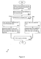
- FIG. 6 that figure presents a flow diagram of the acts that the occupant sensing system 100 may take to determine occupant presence.
- the controller 216 individually switches a head electrode connection and a foot electrode connection to a detection signal output (Act 602).
- the controller 216 determines the head electrode load and a foot electrode load (Act 604). Given the head electrode and foot electrode loads, the controller 216 then determines an occupancy test to apply (Act 606).
- the controller 216 selects a load product occupancy test, the controller 216 proceeds as explained above to form a product of a difference and a sum of load impacts (Act 608).
- the controller 216 also compares the product to upper and lower thresholds to determine seat 100 occupancy, including a front or rear facing child safety seat, and optionally an age characteristic (Act 610).
- the controller 216 selects a ratio occupancy test, the controller 216 proceeds as explained above to form one or more ratios of the electrode loads (Act 612). Based on the result of comparisons against thresholds, the controller 216 may thereby determine vehicle occupancy, including a front or read facing child safety seat, and optionally age information (Act 614).
- the controller 216 may responsively set occupancy indicators in the vehicle (Act 616). Thus, for example, the controller 216 may illuminate a warning lamp on the dashboard. As another example, the controller 216 may issue a voice or sound alarm. As yet another example, the controller 216 outputs a signal to an air bag activation or control system, such as the airbag device 220, to disable airbag activation if appropriate.
- an air bag activation or control system such as the airbag device 220
- the vehicle occupancy sensing system 200 provides a mechanism for determining whether a vehicle is occupied.
- the sensing system 200 may determine that an occupied front or rear facing child seat is present in an automobile and issue appropriate reminders, warnings, and the like.
- the sensing system 200 may thereby helps reduce occurrences of children unintentionally left in vehicles.
- Either or both of the ratio and product occupancy tests may be based upon parameter readings (e.g., load current) for a single upper body electrode (e.g., electrode 120) and a single lower body electrode (e.g., electrode 122).
- the ratio (FL / HL) may be formed with respect to loading currents obtained solely from the head electrode 120 (HL) and solely from the foot electrode 122 (FL).
- either of the ratio and product occupancy tests may employ parameter readings obtained over multiple electrodes.
- the ratio (FL / HL) may be formed with respect to loading currents obtained from two or more of the electrodes 108 - 122.
- the parameter reading HL may be determined from a combination of parameters associated with any two or three of the head electrodes 112, 116, and 120, while the parameter reading FL may be determined from a combination of parameters associated with any two or three of the foot electrodes 114, 118, and 122.
- the product and ratio approaches explained above exemplary approaches that may be taken to determine occupant presence or occupant characteristics.
- alternative tests may be employed, including modified, derivative, or alternate forms of the ratio and product tests.
- the product and ratio tests may both be evaluated to determine if they are in agreement, may be extended to include additional variables (e.g., parameter readings other than load current) and functions (such as differences) of the variables, or may be extended to evaluate contributing effects of multiple electrodes or combinations of electrodes or to incorporate readings obtained from humidity, temperature, or other types of sensors.
- the occupant sensing system 200 determines occupancy characteristics. Thus, in the manner explained above, the sensing system 200 may determine any of occupant presence, occupant facing, and occupant age. The sensing system 200 may, however, be extended to determine additional occupancy characteristics. Thus, for example, the sensing system 200 may be employed to determine occupant size, weight, or other characteristics.
Landscapes
- Engineering & Computer Science (AREA)
- Mechanical Engineering (AREA)
- Computer Networks & Wireless Communication (AREA)
- Aviation & Aerospace Engineering (AREA)
- Transportation (AREA)
- Seats For Vehicles (AREA)
- Air Bags (AREA)
- Chair Legs, Seat Parts, And Backrests (AREA)
Abstract
Description
Claims (22)
- A vehicle occupancy sensing system comprising:a first electrode connection and a second electrode connection, where at least one of the electrode connections is a seat back electrode connection;a circuit parameter sensor connected with the first electrode connection and the second electrode connection; anda controller coupled to the circuit parameter sensor, the controller operable to obtain a first parameter reading for the first electrode connection and a second parameter reading for the second electrode connection, and operable to determine an occupancy characteristic based on at least one of: (a) a ratio of the first and second parameter readings, (b) a product of the first and second parameter readings, and (c) a derivative form of at least one of the ratio and the product.
- The vehicle occupancy sensing system of claim 1, where the first electrode connection is a head electrode connection.
- The vehicle occupancy sensing system of claim 1, where the second electrode connection is a foot electrode connection.
- The vehicle occupancy sensing system of claim 1, further comprising a first electrode coupled to the first electrode connection and a second electrode coupled to the second electrode connection, and wherein the first electrode and the second electrode are separated by at least a pre-selected vehicle cabin feature distance.
- The vehicle occupancy sensing system of claim 4, where the vehicle cabin feature distance is a selected belt-buckle dimension.
- The vehicle occupancy sensing system of claim 1, where the controller is further operable to disable air bag activation based on the determination of occupant presence.
- The vehicle occupancy sensing system of claim 1, where the product comprises at least one of a load impact sum and a load impact difference.
- The vehicle occupancy sensing system of claim 7, where the first parameter reading is a first load reading, where the second parameter reading is a second load reading, and where the load impact sum comprises a sum of load impact based on the first load reading, the second load reading, a first electrode connection unloaded reading, and a second electrode connection unloaded reading.
- The vehicle occupancy sensing system of claim 7, where the first parameter reading is a first load reading, where the second parameter reading is a second load reading, and where the load impact difference comprises a difference of load impact based on the first load reading, the second load reading, a first electrode connection unloaded reading, and a second electrode connection unloaded reading.
- A method for sensing vehicle occupancy comprising the acts of:sensing a first parameter associated with a first electrode connection;sensing a second parameter associated with a second electrode connection, where at least one of the first and second electrode connections is a seat back electrode connection; andcomparing at least one of: (a) a product based on the first and second parameter readings, (b) a ratio based on the first and second parameter readings, and (c) a derivative form of at least one of the ratio and the product.
- The method of claim 10, where the act of comparing comprises comparing against at least one of an upper threshold, a lower threshold, and a ratio threshold that is an occupied child safety seat threshold.
- The method of claim 11, where the upper threshold comprises a rear facing child seat threshold and where the lower threshold comprises a forward facing child seat threshold.
- The method of claim 10, further comprising the act of applying an occupancy test comprising:
- The method of claim 10, where comparing comprises the act of applying a rear facing child safety seat occupancy test comprising:
- The method of claim 10, where comparing comprises the act of applying a front facing child safety seat occupancy test comprising:
- A machine readable medium encoded with instructions that cause a vehicle electronics system to perform a method comprising the acts of:sensing a first parameter associated with a first electrode connection;sensing a second parameter associated with a second electrode connection, where at least one of the first and second electrode connections is a seat back electrode connection; andapplying an occupancy sensing test comprising at least one of:comparing a ratio based on the first and second load readings,comparing a product of the first and second parameter readings, andcomparing a derivative form of at least one of the ratio and the product.
- The machine readable medium of claim 16, where the act of comparing comprises the act of comparing against at least one of a first and second pre-selected threshold that is an occupied child safety seat threshold.
- The machine readable medium of claim 17, where at least one of the first and second pre-selected thresholds is a forward facing child safety seat threshold.
- The machine readable medium of claim 17, where at least one of the first and second pre-selected thresholds is a rear facing child safety seat threshold.
- The machine readable medium of claim 16, where sensing a first load comprises sensing a first load through an upper body electrode coupled to the first electrode connection.
- The machine readable medium of claim 16, where sensing a second load comprises the act of sensing a second load through a lower body electrode coupled to the second electrode connection.
- A vehicle occupancy sensing system comprising:a first electrode in a seat back;a second electrode in the seat back;a third electrode in a seat base, the third electrode non-switchably connected to a relative ground;a circuit parameter sensor connected with the first and second electrodes; anda controller coupled to the circuit parameter sensor, the controller operable to obtain a first parameter reading for the first electrode and a second parameter reading for the second electrode, and operable to output a signal as a function of the first and second load readings.
Applications Claiming Priority (2)
| Application Number | Priority Date | Filing Date | Title |
|---|---|---|---|
| US729655 | 2003-12-05 | ||
| US10/729,655 US7151452B2 (en) | 2003-12-05 | 2003-12-05 | Vehicle occupant sensing system |
Publications (3)
| Publication Number | Publication Date |
|---|---|
| EP1550576A2 true EP1550576A2 (en) | 2005-07-06 |
| EP1550576A3 EP1550576A3 (en) | 2005-07-13 |
| EP1550576B1 EP1550576B1 (en) | 2007-09-19 |
Family
ID=34574707
Family Applications (1)
| Application Number | Title | Priority Date | Filing Date |
|---|---|---|---|
| EP04257507A Expired - Lifetime EP1550576B1 (en) | 2003-12-05 | 2004-12-02 | Vehicle occupant sensing system |
Country Status (9)
| Country | Link |
|---|---|
| US (1) | US7151452B2 (en) |
| EP (1) | EP1550576B1 (en) |
| JP (1) | JP4141436B2 (en) |
| KR (1) | KR100635676B1 (en) |
| BR (1) | BRPI0405295A (en) |
| CA (1) | CA2487205C (en) |
| DE (1) | DE602004009029T2 (en) |
| ES (1) | ES2294440T3 (en) |
| MX (1) | MXPA04012113A (en) |
Families Citing this family (39)
| Publication number | Priority date | Publication date | Assignee | Title |
|---|---|---|---|---|
| JP4529086B2 (en) * | 2005-03-31 | 2010-08-25 | 株式会社デンソー | Occupant detection system |
| US7475903B2 (en) * | 2005-04-08 | 2009-01-13 | Robert Bosch Gmbh | Weight based occupant classification system |
| US7830246B2 (en) * | 2005-10-12 | 2010-11-09 | Elesys North America, Inc. | Occupant sensor and method for seat belt or other monitoring |
| US7791476B2 (en) * | 2006-02-21 | 2010-09-07 | Elesys North America, Inc. | Occupant sensor and method for seat belt or other monitoring |
| EP1837248A1 (en) * | 2006-03-20 | 2007-09-26 | IEE INTERNATIONAL ELECTRONICS & ENGINEERING S.A. | Occupant classification system |
| US20070285218A1 (en) * | 2006-06-09 | 2007-12-13 | 3M Innovative Properties Company | Occupant abandonment sensor for automotive vehicles |
| US7656169B2 (en) * | 2007-02-06 | 2010-02-02 | Iee International Electronics & Engineering S.A. | Capacitive occupant detection system |
| US8437919B2 (en) * | 2007-03-13 | 2013-05-07 | GM Global Technology Operations LLC | Vehicle personalization system |
| US7908777B1 (en) | 2007-08-11 | 2011-03-22 | Beardsley Victoria E | Detachable alert device and method of use |
| US8170745B1 (en) | 2007-09-10 | 2012-05-01 | Jean-Pierre Lors | Seat occupancy verification system for motor vehicles |
| US7966109B2 (en) | 2007-09-14 | 2011-06-21 | Les Innovations Cd Invenio Inc. | Reminder device for eliciting behavioral response in a vehicle |
| US20090295412A1 (en) * | 2008-04-28 | 2009-12-03 | Delphi Technologies, Inc. | Occupant Detector with Electronic Interference Compensation |
| US7876106B2 (en) * | 2008-04-28 | 2011-01-25 | Delphi Technologies, Inc. | System and method for detecting an object at a location |
| US8237455B2 (en) * | 2008-04-28 | 2012-08-07 | Delphi Technologies, Inc. | Occupant detection system with environmental compensation |
| US7880480B2 (en) * | 2008-04-28 | 2011-02-01 | Delphi Technologies, Inc. | Occupant detection system and method for calibrating |
| US8154394B2 (en) * | 2008-05-01 | 2012-04-10 | Delphi Technologies, Inc. | Occupant seat detection system and method |
| US8184013B2 (en) * | 2008-09-05 | 2012-05-22 | Infineon Technologies, Ag | Capacitive detection systems and methods |
| US8358208B2 (en) * | 2008-11-11 | 2013-01-22 | Infineon Technologies Ag | Method and device for sensing a body |
| DE102009019743A1 (en) * | 2009-05-02 | 2010-11-04 | GM Global Technology Operations, Inc., Detroit | Motor vehicle has deactivatable front passenger-air bag and control device for controlling different functions of motor vehicle |
| WO2010131077A1 (en) * | 2009-05-14 | 2010-11-18 | Freescale Semiconductor, Inc. | A child car seat for a land vehicle |
| US8500194B2 (en) * | 2009-11-20 | 2013-08-06 | Delphi Technologies, Inc. | Seat occupant detection circuit isolation from seat heating circuit using a common mode choke |
| US20110133755A1 (en) * | 2009-12-08 | 2011-06-09 | Delphi Technologies, Inc. | System and Method of Occupant Detection with a Resonant Frequency |
| US20110140891A1 (en) * | 2009-12-14 | 2011-06-16 | Delphi Technologies, Inc. | Electrode for an Occupant Sensing System Having Fault Detection and Method of Operating the Same |
| US8400323B2 (en) * | 2009-12-21 | 2013-03-19 | Delphi Technologies, Inc. | Capacitive occupant sensing system and method |
| US20110163878A1 (en) * | 2010-01-07 | 2011-07-07 | Gray Charles A | Capacitive occupant detection system having aging compensation and method |
| US20110190987A1 (en) * | 2010-02-04 | 2011-08-04 | Delphi Technologies, Inc. | Occupant detection system and method |
| US20110190980A1 (en) * | 2010-02-04 | 2011-08-04 | Delphi Technologies, Inc. | Occupant detection system and method |
| US8219286B2 (en) | 2010-04-28 | 2012-07-10 | Delphi Technologies, Inc. | Noise reduction for occupant detection system and method |
| CN103476623B (en) * | 2011-03-09 | 2016-11-09 | Tk控股公司 | System and method for disabling a vehicle |
| US9126502B2 (en) | 2012-08-14 | 2015-09-08 | Delphi Technologies, Inc. | Dual electrode occupant detection system and method |
| CN107484265B (en) | 2013-05-15 | 2020-11-24 | 捷温加拿大有限公司 | Combined heater and sensor and method for heating and sensing |
| KR102089519B1 (en) | 2013-10-11 | 2020-03-16 | 젠썸 캐나다 유엘씨 | Occupancy sensing with heating devices |
| US9550454B1 (en) | 2015-07-02 | 2017-01-24 | Horse Sense Shoes, Llc | Systems and methods for removable vehicle seat sensor |
| WO2017086916A1 (en) * | 2015-11-16 | 2017-05-26 | Roger Roisen | Child vehicle seat occupancy sensor |
| CN107856628A (en) * | 2017-07-07 | 2018-03-30 | 安徽摩尼电子科技有限公司 | A kind of vehicle-mounted child detection alarm device |
| CN109733281A (en) * | 2018-12-11 | 2019-05-10 | 大乘汽车有限公司 | A kind of safety vehicle system and method |
| EP4206667A4 (en) * | 2020-12-04 | 2023-12-13 | Shenzhen Everbest Machinery Industry Co., Ltd. | ALCOHOL DETECTOR BASED ON AIR BLOWING METHOD, AND INTELLIGENT DEVICE |
| DE102021207723A1 (en) | 2021-07-20 | 2022-06-02 | Continental Automotive Gmbh | Method for controlling an automatically adjustable seat of a motor vehicle, taking into account signals from a seat occupancy detection |
| FR3156081B1 (en) * | 2023-11-30 | 2025-12-12 | Faurecia Sieges Dautomobile | Method for detecting the position of a child seat and associated detection system |
Family Cites Families (113)
| Publication number | Priority date | Publication date | Assignee | Title |
|---|---|---|---|---|
| US3943376A (en) | 1973-10-23 | 1976-03-09 | Fairchild Camera And Instrument Corporation | Occupancy detector apparatus for automotive safety systems |
| US6168198B1 (en) | 1992-05-05 | 2001-01-02 | Automotive Technologies International, Inc. | Methods and arrangements for controlling an occupant restraint device in a vehicle |
| US6735506B2 (en) | 1992-05-05 | 2004-05-11 | Automotive Technologies International, Inc. | Telematics system |
| US6474683B1 (en) | 1992-05-05 | 2002-11-05 | Automotive Technologies International Inc. | Method and arrangement for obtaining and conveying information about occupancy of a vehicle |
| US6039139A (en) | 1992-05-05 | 2000-03-21 | Automotive Technologies International, Inc. | Method and system for optimizing comfort of an occupant |
| US6513833B2 (en) | 1992-05-05 | 2003-02-04 | Automotive Technologies International, Inc. | Vehicular occupant motion analysis system |
| US6942248B2 (en) | 1992-05-05 | 2005-09-13 | Automotive Technologies International, Inc. | Occupant restraint device control system and method |
| US6116639A (en) | 1994-05-09 | 2000-09-12 | Automotive Technologies International, Inc. | Vehicle interior identification and monitoring system |
| US6412813B1 (en) | 1992-05-05 | 2002-07-02 | Automotive Technologies International Inc. | Method and system for detecting a child seat |
| US6869100B2 (en) | 1992-05-05 | 2005-03-22 | Automotive Technologies International, Inc. | Method and apparatus for controlling an airbag |
| US6283503B1 (en) | 1992-05-05 | 2001-09-04 | Automotive Technologies International Inc. | Methods and arrangements for determining the position of an occupant in a vehicle |
| US6270116B1 (en) | 1992-05-05 | 2001-08-07 | Automotive Technologies International, Inc. | Apparatus for evaluating occupancy of a seat |
| US7467809B2 (en) | 1992-05-05 | 2008-12-23 | Automotive Technologies International, Inc. | Vehicular occupant characteristic determination system and method |
| US6442465B2 (en) | 1992-05-05 | 2002-08-27 | Automotive Technologies International, Inc. | Vehicular component control systems and methods |
| US6820897B2 (en) | 1992-05-05 | 2004-11-23 | Automotive Technologies International, Inc. | Vehicle object detection system and method |
| US6422595B1 (en) | 1992-05-05 | 2002-07-23 | Automotive Technologies International, Inc. | Occupant position sensor and method and arrangement for controlling a vehicular component based on an occupant's position |
| US6778672B2 (en) | 1992-05-05 | 2004-08-17 | Automotive Technologies International Inc. | Audio reception control arrangement and method for a vehicle |
| US6782316B2 (en) | 1995-06-07 | 2004-08-24 | Automotive Technologies International, Inc. | Apparatus and method for adjusting a steering wheel |
| US5829782A (en) | 1993-03-31 | 1998-11-03 | Automotive Technologies International, Inc. | Vehicle interior identification and monitoring system |
| US6712387B1 (en) | 1992-05-05 | 2004-03-30 | Automotive Technologies International, Inc. | Method and apparatus for controlling deployment of a side airbag |
| US6689962B2 (en) | 1995-06-07 | 2004-02-10 | Automotive Technologies International, Inc | Weight measuring system and method used with a spring system of a seat |
| JPS60152904A (en) | 1984-01-20 | 1985-08-12 | Nippon Denso Co Ltd | Vehicle-driver-position recognizing apparatus |
| US4846368A (en) | 1986-10-03 | 1989-07-11 | Trw Vehicle Safety Systems Inc. | Inflatable restraint system |
| DE3802159C2 (en) | 1988-01-26 | 1996-09-05 | Porsche Ag | Seat occupancy detection device |
| DE3809074A1 (en) | 1988-03-18 | 1989-10-05 | Audi Ag | Safety system for motor vehicles, including an inflatable crash protection cushion |
| US5074583A (en) | 1988-07-29 | 1991-12-24 | Mazda Motor Corporation | Air bag system for automobile |
| US5231253A (en) | 1989-02-23 | 1993-07-27 | Automotive Technologies, International | Side impact sensors |
| US5071160A (en) | 1989-10-02 | 1991-12-10 | Automotive Systems Laboratory, Inc. | Passenger out-of-position sensor |
| DE4005598C2 (en) | 1990-02-22 | 2000-06-15 | Bosch Gmbh Robert | Protection procedure for vehicle occupants and device for carrying out the procedure |
| JPH04135945A (en) | 1990-09-28 | 1992-05-11 | Ikeda Bussan Co Ltd | Protective device for rider |
| US5772238A (en) | 1995-12-12 | 1998-06-30 | Automotive Technologies International Inc. | Efficient airbag module |
| US6326704B1 (en) | 1995-06-07 | 2001-12-04 | Automotive Technologies International Inc. | Vehicle electrical system |
| US6484080B2 (en) | 1995-06-07 | 2002-11-19 | Automotive Technologies International Inc. | Method and apparatus for controlling a vehicular component |
| US6533316B2 (en) | 1995-06-07 | 2003-03-18 | Automotive Technologies International, Inc. | Automotive electronic safety network |
| US6175787B1 (en) | 1995-06-07 | 2001-01-16 | Automotive Technologies International Inc. | On board vehicle diagnostic module using pattern recognition |
| US6179326B1 (en) | 1995-10-30 | 2001-01-30 | Automotive Technologies International, Inc. | Efficient airbag system |
| US5809437A (en) | 1995-06-07 | 1998-09-15 | Automotive Technologies International, Inc. | On board vehicle diagnostic module using pattern recognition |
| US6738697B2 (en) | 1995-06-07 | 2004-05-18 | Automotive Technologies International Inc. | Telematics system for vehicle diagnostics |
| EP0560351B1 (en) | 1992-03-13 | 1997-12-29 | Matsushita Electric Industrial Co., Ltd. | Presence detecting and safety control apparatus |
| US6833516B2 (en) | 1995-06-07 | 2004-12-21 | Automotive Technologies International, Inc. | Apparatus and method for controlling a vehicular component |
| US6242701B1 (en) | 1995-06-07 | 2001-06-05 | Automotive Technologies International, Inc. | Apparatus and method for measuring weight of an occupying item of a seat |
| US6784379B2 (en) | 1995-06-07 | 2004-08-31 | Automotive Technologies International, Inc. | Arrangement for obtaining information about an occupying item of a seat |
| US6325414B2 (en) | 1992-05-05 | 2001-12-04 | Automotive Technologies International Inc. | Method and arrangement for controlling deployment of a side airbag |
| US5943295A (en) | 1997-02-06 | 1999-08-24 | Automotive Technologies International Inc. | Method for identifying the presence and orientation of an object in a vehicle |
| US6529809B1 (en) | 1997-02-06 | 2003-03-04 | Automotive Technologies International, Inc. | Method of developing a system for identifying the presence and orientation of an object in a vehicle |
| US6748797B2 (en) | 2000-09-08 | 2004-06-15 | Automotive Technologies International Inc. | Method and apparatus for monitoring tires |
| US6793242B2 (en) | 1994-05-09 | 2004-09-21 | Automotive Technologies International, Inc. | Method and arrangement for obtaining and conveying information about occupancy of a vehicle |
| US6746078B2 (en) | 1997-12-17 | 2004-06-08 | Automotive Technologies International, Inc. | System and method for moving a headrest based on anticipatory sensing |
| US6445988B1 (en) | 1997-02-06 | 2002-09-03 | Automotive Technologies International Inc. | System for determining the occupancy state of a seat in a vehicle and controlling a component based thereon |
| US6757602B2 (en) | 1997-02-06 | 2004-06-29 | Automotive Technologies International, Inc. | System for determining the occupancy state of a seat in a vehicle and controlling a component based thereon |
| US6397136B1 (en) | 1997-02-06 | 2002-05-28 | Automotive Technologies International Inc. | System for determining the occupancy state of a seat in a vehicle |
| US6958451B2 (en) | 1995-06-07 | 2005-10-25 | Automotive Technologies International, Inc. | Apparatus and method for measuring weight of an occupying item of a seat |
| US6088640A (en) | 1997-12-17 | 2000-07-11 | Automotive Technologies International, Inc. | Apparatus for determining the location of a head of an occupant in the presence of objects that obscure the head |
| US6662642B2 (en) | 2000-09-08 | 2003-12-16 | Automotive Technologies International, Inc. | Vehicle wireless sensing and communication system |
| US6081757A (en) | 1995-06-07 | 2000-06-27 | Automotive Technologies International, Inc. | Seated-state detecting apparatus |
| US6078854A (en) | 1995-06-07 | 2000-06-20 | Automotive Technologies International, Inc. | Apparatus and method for adjusting a vehicle component |
| US6792342B2 (en) | 1995-06-07 | 2004-09-14 | Automotive Technologies International, Inc. | Apparatus and method for controlling a vehicular component |
| US6653577B2 (en) | 1995-06-07 | 2003-11-25 | Automotive Technologies | Apparatus and method for measuring weight of an occupying item of a seat |
| US6648367B2 (en) | 1995-06-07 | 2003-11-18 | Automotive Technologies International Inc. | Integrated occupant protection system |
| US6442504B1 (en) | 1995-06-07 | 2002-08-27 | Automotive Technologies International, Inc. | Apparatus and method for measuring weight of an object in a seat |
| USRE37736E1 (en) | 1992-05-05 | 2002-06-11 | Automotive Technologies International Inc. | Vehicle occupant position and velocity sensor |
| US5822707A (en) | 1992-05-05 | 1998-10-13 | Automotive Technologies International, Inc. | Automatic vehicle seat adjuster |
| US5330226A (en) | 1992-12-04 | 1994-07-19 | Trw Vehicle Safety Systems Inc. | Method and apparatus for detecting an out of position occupant |
| DE4492128C2 (en) | 1993-03-31 | 2003-01-02 | Automotive Tech Int | Position and speed sensor for vehicle occupants |
| BR9407064A (en) | 1993-06-22 | 1996-03-12 | Vos Verkehrs Optimierungs Syst | Device for detecting the presence of people on seats |
| US5844415A (en) | 1994-02-03 | 1998-12-01 | Massachusetts Institute Of Technology | Method for three-dimensional positions, orientation and mass distribution |
| US5914610A (en) * | 1994-02-03 | 1999-06-22 | Massachusetts Institute Of Technology | Apparatus and method for characterizing movement of a mass within a defined space |
| US5607180A (en) | 1994-02-23 | 1997-03-04 | Kornhauser; Murray | Airbag inflation devices and methods |
| US5482314A (en) | 1994-04-12 | 1996-01-09 | Aerojet General Corporation | Automotive occupant sensor system and method of operation by sensor fusion |
| US5901978A (en) | 1994-05-09 | 1999-05-11 | Automotive Technologies International, Inc. | Method and apparatus for detecting the presence of a child seat |
| US5602734A (en) | 1994-09-23 | 1997-02-11 | Advanced Safety Concepts, Inc. | Automobile air bag systems |
| US5802479A (en) | 1994-09-23 | 1998-09-01 | Advanced Safety Concepts, Inc. | Motor vehicle occupant sensing systems |
| US5691693A (en) | 1995-09-28 | 1997-11-25 | Advanced Safety Concepts, Inc. | Impaired transportation vehicle operator system |
| US5770997A (en) | 1995-06-26 | 1998-06-23 | Alliedsignal Inc. | Vehicle occupant sensing system |
| JPH09150703A (en) * | 1995-09-25 | 1997-06-10 | Tokai Rika Co Ltd | Occupant protective device for vehicle |
| US5732375A (en) | 1995-12-01 | 1998-03-24 | Delco Electronics Corp. | Method of inhibiting or allowing airbag deployment |
| US6012007A (en) | 1995-12-01 | 2000-01-04 | Delphi Technologies, Inc. | Occupant detection method and apparatus for air bag system |
| DE19547842A1 (en) | 1995-12-21 | 1997-06-26 | Bosch Gmbh Robert | Detection of occupancy especially of passenger seat in motor vehicle |
| USRE37260E1 (en) | 1996-02-08 | 2001-07-03 | Automotive Technologies International Inc. | Method for identifying the presence and orientation of an object in a vehicle |
| US6161070A (en) | 1996-02-23 | 2000-12-12 | Nec Home Electronics, Inc. | Passenger detection system |
| US5948031A (en) | 1996-02-23 | 1999-09-07 | Nec Technologies, Inc. | Vehicle passenger sensing system and method |
| US5808552A (en) | 1996-11-25 | 1998-09-15 | Hill-Rom, Inc. | Patient detection system for a patient-support device |
| US5878620A (en) | 1997-01-23 | 1999-03-09 | Schlege Systems, Inc. | Conductive fabric sensor for vehicle seats |
| US6043743A (en) * | 1997-02-26 | 2000-03-28 | Nec Corporation | Passenger detecting system and passenger detecting method |
| US5954360A (en) | 1997-09-18 | 1999-09-21 | Breed Automotive Technology, Inc. | Vehicle occupant sensing apparatus and method |
| US6014062A (en) * | 1998-04-21 | 2000-01-11 | Applied Micro Circuits Corporation | Control circuit for a complementary metal-oxide semiconductor voltage controlled oscillator |
| US6283504B1 (en) * | 1998-12-30 | 2001-09-04 | Automotive Systems Laboratory, Inc. | Occupant sensor |
| US6329914B1 (en) | 1999-10-05 | 2001-12-11 | Nec Technologies, Inc. | Thickness measurement system and method for vehicle occupant detection |
| US6329913B1 (en) | 1999-10-05 | 2001-12-11 | Nec Technologies, Inc. | Passenger detection system and method |
| US6527296B2 (en) * | 2000-03-17 | 2003-03-04 | Trw Vehicle Safety Systems Inc. | Inflatable side curtain |
| US6565118B2 (en) * | 2000-05-23 | 2003-05-20 | Trw Vehicle Safety Systems Inc. | Folded inflatable curtain |
| US6273458B1 (en) * | 2000-05-31 | 2001-08-14 | Trw Vehicle Safety Systems Inc. | Inflatable curtain |
| US6397135B1 (en) | 2000-07-13 | 2002-05-28 | Aisin Seiki Kabushiki Kaisha | Rear-wheel steering angle control device |
| US6454296B1 (en) * | 2000-11-22 | 2002-09-24 | Delphi Technologies, Inc. | Side air bag for roll-over restraint |
| US6435545B1 (en) * | 2000-12-05 | 2002-08-20 | Trw Vehicle Safety Systems Inc. | Inflatable curtain with anchor device |
| US6474681B2 (en) * | 2001-02-07 | 2002-11-05 | Trw Vehicle Safety Systems Inc. | Inflatable curtain with anchor device |
| JP2002333366A (en) | 2001-05-08 | 2002-11-22 | Aisin Seiki Co Ltd | Occupant judgment device |
| US6783152B2 (en) * | 2001-05-23 | 2004-08-31 | Toyoda Gosei Co., Ltd. | Head protecting airbag device |
| US6696948B2 (en) | 2001-11-02 | 2004-02-24 | Elesys North America, Inc. | Wet seat protection for air bag control occupant detection |
| US6688641B2 (en) * | 2001-12-13 | 2004-02-10 | Autoliv Asp, Inc. | Compact tethering system and method for an inflatable curtain |
| US6733035B2 (en) * | 2002-03-05 | 2004-05-11 | Delphi Technologies, Inc. | Side curtain air bag assembly |
| JP3928451B2 (en) * | 2002-03-20 | 2007-06-13 | 豊田合成株式会社 | Head protection airbag device |
| US7065438B2 (en) | 2002-04-26 | 2006-06-20 | Elesys North America, Inc. | Judgment lock for occupant detection air bag control |
| US20040000992A1 (en) * | 2002-06-28 | 2004-01-01 | Ford Global Technologies, Inc. | Crash notification system for an automotive vehicle |
| JP4045884B2 (en) * | 2002-07-22 | 2008-02-13 | タカタ株式会社 | Curtain airbag guide member and curtain airbag device |
| US20050046159A1 (en) * | 2003-09-01 | 2005-03-03 | Takata Corporation | Curtain airbag apparatus |
| JP4376596B2 (en) * | 2003-11-19 | 2009-12-02 | タカタ株式会社 | Airbag device |
| JP4273944B2 (en) * | 2003-12-02 | 2009-06-03 | タカタ株式会社 | Head protection airbag device and vehicle |
| JP4396260B2 (en) * | 2003-12-19 | 2010-01-13 | タカタ株式会社 | Curtain airbag device |
| JP4269929B2 (en) * | 2003-12-19 | 2009-05-27 | タカタ株式会社 | Curtain airbag guide device and curtain airbag device |
| JP4269928B2 (en) * | 2003-12-19 | 2009-05-27 | タカタ株式会社 | Curtain airbag guide device and curtain airbag device |
| JP4289147B2 (en) * | 2003-12-22 | 2009-07-01 | タカタ株式会社 | Curtain airbag guide device and curtain airbag device |
| JP2005186654A (en) * | 2003-12-24 | 2005-07-14 | Takata Corp | Curtain airbag device |
-
2003
- 2003-12-05 US US10/729,655 patent/US7151452B2/en not_active Expired - Fee Related
-
2004
- 2004-11-10 CA CA002487205A patent/CA2487205C/en not_active Expired - Fee Related
- 2004-12-02 EP EP04257507A patent/EP1550576B1/en not_active Expired - Lifetime
- 2004-12-02 DE DE602004009029T patent/DE602004009029T2/en not_active Expired - Lifetime
- 2004-12-02 ES ES04257507T patent/ES2294440T3/en not_active Expired - Lifetime
- 2004-12-03 KR KR1020040100734A patent/KR100635676B1/en not_active Expired - Fee Related
- 2004-12-03 MX MXPA04012113A patent/MXPA04012113A/en active IP Right Grant
- 2004-12-06 BR BR0405295-1A patent/BRPI0405295A/en not_active IP Right Cessation
- 2004-12-06 JP JP2004353177A patent/JP4141436B2/en not_active Expired - Fee Related
Also Published As
| Publication number | Publication date |
|---|---|
| US7151452B2 (en) | 2006-12-19 |
| EP1550576B1 (en) | 2007-09-19 |
| JP2005170378A (en) | 2005-06-30 |
| EP1550576A3 (en) | 2005-07-13 |
| ES2294440T3 (en) | 2008-04-01 |
| BRPI0405295A (en) | 2005-08-30 |
| MXPA04012113A (en) | 2006-07-28 |
| KR20050054835A (en) | 2005-06-10 |
| JP4141436B2 (en) | 2008-08-27 |
| DE602004009029T2 (en) | 2008-06-12 |
| KR100635676B1 (en) | 2006-10-17 |
| US20050121885A1 (en) | 2005-06-09 |
| CA2487205C (en) | 2008-08-26 |
| CA2487205A1 (en) | 2005-06-05 |
| DE602004009029D1 (en) | 2007-10-31 |
Similar Documents
| Publication | Publication Date | Title |
|---|---|---|
| EP1550576B1 (en) | Vehicle occupant sensing system | |
| US8237455B2 (en) | Occupant detection system with environmental compensation | |
| KR101050005B1 (en) | Passenger detection sensor and method for monitoring seat belts or others | |
| US7830246B2 (en) | Occupant sensor and method for seat belt or other monitoring | |
| US7808395B2 (en) | Occupancy detecting method and system | |
| US7880480B2 (en) | Occupant detection system and method for calibrating | |
| EP1669251A1 (en) | Child seat detection system | |
| US6922152B2 (en) | Passenger weight measuring apparatus | |
| US20070132559A1 (en) | Seat occupancy detection system | |
| US7866691B2 (en) | Occupant classifying device for vehicle seat | |
| US6526806B2 (en) | Apparatus for occupant classification in a vehicle | |
| US20050016786A1 (en) | Vehicle seat and control unit | |
| JP4032024B2 (en) | Device for classifying seat occupancy in a car | |
| US20080208414A1 (en) | Control Apparatus For an Occupant Protection Means in a Motor Vehicle | |
| JP3140286B2 (en) | Human body detection device |
Legal Events
| Date | Code | Title | Description |
|---|---|---|---|
| PUAI | Public reference made under article 153(3) epc to a published international application that has entered the european phase |
Free format text: ORIGINAL CODE: 0009012 |
|
| PUAL | Search report despatched |
Free format text: ORIGINAL CODE: 0009013 |
|
| AK | Designated contracting states |
Kind code of ref document: A2 Designated state(s): AT BE BG CH CY CZ DE DK EE ES FI FR GB GR HU IE IS IT LI LT LU MC NL PL PT RO SE SI SK TR |
|
| AX | Request for extension of the european patent |
Extension state: AL BA HR LV MK YU |
|
| AK | Designated contracting states |
Kind code of ref document: A3 Designated state(s): AT BE BG CH CY CZ DE DK EE ES FI FR GB GR HU IE IS IT LI LT LU MC NL PL PT RO SE SI SK TR |
|
| AX | Request for extension of the european patent |
Extension state: AL BA HR LV MK YU |
|
| 17P | Request for examination filed |
Effective date: 20051118 |
|
| AKX | Designation fees paid |
Designated state(s): DE ES FR GB IT SE |
|
| RAP1 | Party data changed (applicant data changed or rights of an application transferred) |
Owner name: ELESYS NORTH AMERICA INC. |
|
| GRAP | Despatch of communication of intention to grant a patent |
Free format text: ORIGINAL CODE: EPIDOSNIGR1 |
|
| GRAS | Grant fee paid |
Free format text: ORIGINAL CODE: EPIDOSNIGR3 |
|
| GRAA | (expected) grant |
Free format text: ORIGINAL CODE: 0009210 |
|
| AK | Designated contracting states |
Kind code of ref document: B1 Designated state(s): DE ES FR GB IT SE |
|
| REG | Reference to a national code |
Ref country code: GB Ref legal event code: FG4D |
|
| REF | Corresponds to: |
Ref document number: 602004009029 Country of ref document: DE Date of ref document: 20071031 Kind code of ref document: P |
|
| REG | Reference to a national code |
Ref country code: SE Ref legal event code: TRGR |
|
| REG | Reference to a national code |
Ref country code: ES Ref legal event code: FG2A Ref document number: 2294440 Country of ref document: ES Kind code of ref document: T3 |
|
| ET | Fr: translation filed | ||
| PLBE | No opposition filed within time limit |
Free format text: ORIGINAL CODE: 0009261 |
|
| STAA | Information on the status of an ep patent application or granted ep patent |
Free format text: STATUS: NO OPPOSITION FILED WITHIN TIME LIMIT |
|
| 26N | No opposition filed |
Effective date: 20080620 |
|
| PG25 | Lapsed in a contracting state [announced via postgrant information from national office to epo] |
Ref country code: FR Free format text: LAPSE BECAUSE OF NON-PAYMENT OF DUE FEES Effective date: 20091231 |
|
| PGFP | Annual fee paid to national office [announced via postgrant information from national office to epo] |
Ref country code: GB Payment date: 20101123 Year of fee payment: 7 Ref country code: IT Payment date: 20101213 Year of fee payment: 7 |
|
| PGFP | Annual fee paid to national office [announced via postgrant information from national office to epo] |
Ref country code: ES Payment date: 20111214 Year of fee payment: 8 Ref country code: FR Payment date: 20111205 Year of fee payment: 8 Ref country code: SE Payment date: 20111207 Year of fee payment: 8 |
|
| PGFP | Annual fee paid to national office [announced via postgrant information from national office to epo] |
Ref country code: DE Payment date: 20111230 Year of fee payment: 8 |
|
| PG25 | Lapsed in a contracting state [announced via postgrant information from national office to epo] |
Ref country code: SE Free format text: LAPSE BECAUSE OF NON-PAYMENT OF DUE FEES Effective date: 20121203 |
|
| GBPC | Gb: european patent ceased through non-payment of renewal fee |
Effective date: 20121202 |
|
| REG | Reference to a national code |
Ref country code: FR Ref legal event code: ST Effective date: 20130830 |
|
| REG | Reference to a national code |
Ref country code: DE Ref legal event code: R119 Ref document number: 602004009029 Country of ref document: DE Effective date: 20130702 |
|
| PG25 | Lapsed in a contracting state [announced via postgrant information from national office to epo] |
Ref country code: DE Free format text: LAPSE BECAUSE OF NON-PAYMENT OF DUE FEES Effective date: 20130702 |
|
| PG25 | Lapsed in a contracting state [announced via postgrant information from national office to epo] |
Ref country code: FR Free format text: LAPSE BECAUSE OF NON-PAYMENT OF DUE FEES Effective date: 20130102 Ref country code: GB Free format text: LAPSE BECAUSE OF NON-PAYMENT OF DUE FEES Effective date: 20121202 |
|
| PG25 | Lapsed in a contracting state [announced via postgrant information from national office to epo] |
Ref country code: IT Free format text: LAPSE BECAUSE OF NON-PAYMENT OF DUE FEES Effective date: 20121202 |
|
| REG | Reference to a national code |
Ref country code: ES Ref legal event code: FD2A Effective date: 20140306 |
|
| PG25 | Lapsed in a contracting state [announced via postgrant information from national office to epo] |
Ref country code: ES Free format text: LAPSE BECAUSE OF NON-PAYMENT OF DUE FEES Effective date: 20121203 |