EP1550566A1 - Run-flat core - Google Patents
Run-flat core Download PDFInfo
- Publication number
- EP1550566A1 EP1550566A1 EP03723403A EP03723403A EP1550566A1 EP 1550566 A1 EP1550566 A1 EP 1550566A1 EP 03723403 A EP03723403 A EP 03723403A EP 03723403 A EP03723403 A EP 03723403A EP 1550566 A1 EP1550566 A1 EP 1550566A1
- Authority
- EP
- European Patent Office
- Prior art keywords
- core
- blocks
- run
- tire
- belt
- Prior art date
- Legal status (The legal status is an assumption and is not a legal conclusion. Google has not performed a legal analysis and makes no representation as to the accuracy of the status listed.)
- Granted
Links
Images


Classifications
-
- B—PERFORMING OPERATIONS; TRANSPORTING
- B60—VEHICLES IN GENERAL
- B60C—VEHICLE TYRES; TYRE INFLATION; TYRE CHANGING; CONNECTING VALVES TO INFLATABLE ELASTIC BODIES IN GENERAL; DEVICES OR ARRANGEMENTS RELATED TO TYRES
- B60C17/00—Tyres characterised by means enabling restricted operation in damaged or deflated condition; Accessories therefor
- B60C17/04—Tyres characterised by means enabling restricted operation in damaged or deflated condition; Accessories therefor utilising additional non-inflatable supports which become load-supporting in emergency
- B60C17/041—Tyres characterised by means enabling restricted operation in damaged or deflated condition; Accessories therefor utilising additional non-inflatable supports which become load-supporting in emergency characterised by coupling or locking means between rim and support
-
- B—PERFORMING OPERATIONS; TRANSPORTING
- B60—VEHICLES IN GENERAL
- B60C—VEHICLE TYRES; TYRE INFLATION; TYRE CHANGING; CONNECTING VALVES TO INFLATABLE ELASTIC BODIES IN GENERAL; DEVICES OR ARRANGEMENTS RELATED TO TYRES
- B60C17/00—Tyres characterised by means enabling restricted operation in damaged or deflated condition; Accessories therefor
- B60C17/10—Internal lubrication
-
- B—PERFORMING OPERATIONS; TRANSPORTING
- B60—VEHICLES IN GENERAL
- B60C—VEHICLE TYRES; TYRE INFLATION; TYRE CHANGING; CONNECTING VALVES TO INFLATABLE ELASTIC BODIES IN GENERAL; DEVICES OR ARRANGEMENTS RELATED TO TYRES
- B60C19/00—Tyre parts or constructions not otherwise provided for
- B60C2019/006—Warning devices, e.g. devices generating noise due to flat or worn tyres
Definitions
- the present invention relates to a core housed inside a tire and fastened to a wheel rim so that even when the tire is punctured (so that it becomes flat), the core supports the tire from inside to thereby cause a vehicle to be able to run further than it could without the core (hereinafter, a run-flat core).
- a run-flat tire is being developed from the following two viewpoints:
- the spare tire, the wheel for mounting the tire, the tool associated with the spare and the jack can be omitted.
- a driver is not exposed to crime or other danger because the vehicle can run further even when a tire-puncture happens.
- Type A core-type
- type B side wall reinforced-type
- the number of parts is relatively large, accompanied by an increase in cost.
- Type B (Side wall reinforcing-type):
- the type B (the side wall reinforcing type) tire is interchangeable with a standard non-run-flat tire and rim, the type B tire is more acceptable than the type A tire.
- Various methods for reinforcing the side wall have been proposed. However, those methods are not widely used for the following reasons:
- the aspect ratio should be equal to or less than 60%.
- the weight of the tire and wheel is increased significantly.
- Type C Combination of a wheel on which a tire can be laterally mounted and a run-flat core:
- a third method was proposed by the present applicant in Japanese Patent Application No. 2001-352191.
- an integral run-flat core having a notch is mounted to a wheel on which a tire can be laterally mounted. Since a structure according to the third method is not accompanied by a change in a tire structure, the structure is here called a run-flat core.
- the structure includes a core having a plurality of notches on a circumference of the core and a rim having a divisional structure (wherein a flange at one end of the rim is divided from a remaining main portion of the rim and is dismountable from the main portion of the rim).
- the core is mounted to the rim laterally (in an axial direction of the rim).
- An object of the present invention is to provide a run-flat core wherein the core is lighter, insertion of the core into a tire is easier, and pressing the core to a wheel rim is easier, than in the above-described type C structure.
- a run-flat core according to the present invention to achieve the above-described object may be described as follows:
- the run-flat core includes a plurality of blocks.
- Each of the plurality of blocks has a shape of a hollow box including a closed upper surface and an open lower surface.
- Each of the plurality of blocks includes a reinforcing lattice plate or rib therein.
- the run-flat core is disposed outside a rim of a wheel and inside a tire with a vertical direction of each of the plurality of blocks directed in a radial direction of the wheel and with the upper surface of each of the plurality of blocks directed in a radially outside direction of the wheel.
- the block of the core since the block of the core has the shape of a hollow box closed at the upper surface and the reinforcing lattice plate or rib is provided in the box, the core is light, yet sufficiently strong to bear the load.
- a core of the above-described C structure has a volume of about 0.8L (L: liter) per one protruded portion (a portion between adjacent notches).
- L liter
- the density of the material of the protruded portion is about 1 g/cc
- the weight of the protrusion is about 0.8 kg
- the weight of all of the protrusions is about 10 kg.
- the core is too heavy.
- the material of the core can be changed to synthetic resin or a reinforced synthetic resin (for example, a glass-fiber mixed synthetic resin, having a density of about 1.5 - about 1.7 g/cc), and the block portion (corresponding to the protruded portion) can be constructed as a hollow structure to thereby lighten the core.
- a reinforced synthetic resin for example, a glass-fiber mixed synthetic resin, having a density of about 1.5 - about 1.7 g/cc
- the vehicle In a run-flat system, the vehicle should be able to run over a distance of 200km after the tire is punctured.
- the core When the tire is punctured, the core must bear the weight of the vehicle.
- the vehicle runs about 2m per round of the tire.
- the core receives the weight (W) of the vehicle repeatedly, about 1,000,000 times.
- the core should withstand front-and-rear loads and right-and-left loads (estimated as 70% of the weight of the vehicle, i.e., 0.7W) due to braking and turning, about 1% of the times of the vertical loads (i.e., 10,000 times).
- EFM finite element method
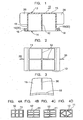
- the core 10 includes a plurality of blocks (or core blocks) 15 made from synthetic resin or reinforced synthetic resin or the like and manufactured through injection forming or the like.
- Each block 15 has a structure which is able to bear the vertical loads, the front-and-rear loads and the right-and-left loads and is able to be easily manufactured through injection forming. More particularly, the block 15 has a shape of a box 11 having a closed upper surface 13, a closed side surface and an open lower surface 14.
- the block 15 has a (for example, lattice-shaped) reinforcing plate (or rib) 12 inside the box 11.
- the vertical direction corresponds to a radial direction of the wheel when the core is mounted to the wheel
- the up direction corresponds to a radially outward direction of the wheel
- the down direction corresponds to a radially inward direction of the wheel.
- a longitudinal groove may be formed in the upper surface 13.
- the upper surface 13 is closed to bear the front-and-rear force and the right-and-left force.
- the reinforcing plate 12 is provided for reinforcing an entire portion of the block.
- the lattice can have any of a variety of shapes. Examples are illustrated in FIGs. 4A - 4D.
- a weight of one block can be about 0.3 kg (corresponding to a case of a 17 inch wheel). This satisfies an aimed weight.
- the core will be large, accompanied by an increase in the weight of the core, and made by a large and costly metallic forming molding machine. Further, the efficiency associated with transporting the core is low because of the large volume.
- the aforementioned structure C proposed by the present applicant is not a uniform, flat structure in a longitudinal direction thereof for improving "an insertion property" and "prevention of a columnar resonance", but a single annular band structure having six to fifteen protrusions in the band.
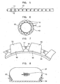
- core 10 is formed as blocks 15 independent of each other, and the separate blocks are connected to each other at connecting portions 17 thereby forming a core 10 formed in a chain of blocks (FIGs. 5 - 7).
- Each block is of a comparatively small size, so that the manufacturing cost and a transport cost are decreased. Further, it becomes easier to insert the core into the tire 50.
- connection of the blocks 15 should be performed before the tire 50 is mounted to the rim 38, because connection after mounting the tire to the rim is difficult because of little space. Accordingly, mounting of the core 10 to the rim 38 is performed in the following steps:
- one of the axially opposite end flanges of the rim 38 (for example, a right flange in FIG. 27) is constructed so as to be dismountable from a remaining, main portion of the rim. With the flange dismounted, the tire and the core 10 inserted inside the tire are mounted to the rim 38 in a lateral direction (in an axial direction of the wheel).
- the core blocks are connected by means of a split pin connector, as illustrated in FIGs. 7 and 8, or a hook connector, as illustrated in FIGs. 22 and 23. Since a large force does not act on the connecting portion 17 after the core blocks 15 are fastened to the rim 38, a sufficient connecting strength is obtained by the split pin 16 only.
- an outside diameter of the split pin is selected to be sufficiently smaller than an inside diameter of a hole formed in the connection bracket, so that a smooth pivotal motion is obtained at the connecting portion 17, whereby insertion of the core 10 inside the tire 50 is easy.
- connecting portion 17 can be located at about a mid-height of the core, so that a good pivot motion of the core is obtained at the connecting portion.
- An inside diameter of the core 10 can be greater than an outer diameter of a rim portion when the core is mounted so that mounting of the core to the rim 38 is easy. Therefore, as the core is mounted onto the rim, the core 10 may not contact the rim fully. If the vehicle moves in this state, the core may move inside the tire and will generate noise.
- a centrifugal force acts on the core 10.
- the core can be fastened to the rim so that the core does not float up from the rim even if centrifugal force acts the core.
- the core blocks 15 are connected to each other by a hinge structure 21 at a lower portion of the block in a height direction of the block, wherein the blocks are pressed to the rim by a tension which is generated in the core due to a bending reaction force of a hinge bar 22.
- the hinge structure 21 includes protrusions formed in adjacent blocks 15 and protruding toward the opposing blocks 15. Holes are formed in the protrusions, and the hinge bar 22 extends through the holes so that the adjacent blocks 15 are pivotal about the hinge bar 22.
- the chain of blocks which is not yet connected at opposite ends thereof is inserted into the tire and is mounted onto the rim together with the tire. Then, the opposite ends are pulled so as to be close to each other and are connected to each other.
- a bending force acts on all of the hinge structures 21 whereby a tension which is a reaction force of the bending force of the hinge bars 22 is generated in the core in the circumferential direction of the wheel.
- the core block acts as a partition for the columnar space inside the tire thereby changing the columnar resonance frequency of the assembly and preventing noise caused by columnar resonance.
- the block can have a cross-sectional area larger than seventy percent of the cross-sectional area of the space inside the tire.
- the core block 15 it is difficult to design the core block 15 so that its cross-sectional area is greater than seventy percent of the cross-sectional area of the space inside the tire, especially while attempting to lighten the core while keeping the necessary strength, enable easy insertion of the core into the tire, and provide a structure for pressing the core to the wheel.
- fins 36 can be provided protruding outwardly in right and left directions at outside surfaces of the right and left side walls of the core block 15.
- Each fin 36 is designed such that it partitions the columnar space 37 inside the tire 50 and does little to increase the weight of the block, while not hindering insertion of the core and pressing the core to the wheel.
- the core 10 can take any of the following structures:
- the core 10 is divided into a plurality of, for example, six to fifteen blocks 15 made from synthetic resin.
- the blocks are connected in an annular connected chain before the core is inserted into the tire 50.
- the annularly connected core 10 is pivotally bent and inserted into the tire 50 like a snake toy.
- Each block connecting portion 17 may be a connection by a pin 16 (see FIGs. 7 and 8).
- a relatively large clearance is provided between the pin 16 and the pin hole so that a flexible structure (a structure able move through a large pivotal motion) is obtained, insertion of the core into the tire 50 is easy.
- a core 10 having a required height can be inserted into a tire having an aspect ration equal to or less than about 50%.
- the core 10 is pressed to the wheel rim such that a relatively large tension does not act on the connecting portion 17, so that the connecting structure can be simple and light.
- the tension is generated by a system different from the connecting structure, such as the belt 19 or wire 20.
- the connecting structure between the blocks can use the pin 16 or the hook 35 to ease manufacturing, enable connection through a small gap between the tire and the core after insertion of the core into the tire, and maintain flexibility at the connecting portion 17.
- the hook can be a synthetic resin hook 35A (FIG. 22) or a metallic hook 35B (FIG. 23). Where the block 15 is made from synthetic resin, the synthetic resin hook 35A is formed integrally with the block, whereby an additional member is unnecessary and a cost advantage is obtained.
- the metallic hook 35B can be threaded through a latch in the core block 15.
- the pin connecting structure and the hook connecting structure described in item (4-1) above are examples of connecting structures where connection is easy in a small space and can be used for connection of the opposite ends of the linear chain core described in item (4-2).
- the chain of blocks where a plurality of blocks 15 are connected into the form of a chain may be replaced by a core made in the form of a single block, as illustrated in FIGs. 25A and 25B.
- the single block core 10 is made straight or annular, and opposite ends of the core 10 are connected.
- the core 10 can be inserted into the tire 50 having an aspect ratio up to about 50%. After the core 10 is inserted into the tire 50, the opposite ends of the core are connected (FIG. 25B).
- the connecting structure can not only connect the ends of the core 10, but also press the core to the rim.
- the aforementioned intermediate link 29 (FIGs. 16A and 16B) or the buckle arrangement (FIGs. 24A and 24B) described below can be used.
- a U-shaped bar 41 fixed to an opposing block 15 is hooked by a rotatable hook 42 so that the core 10 is connected. Then, the hook 42 is rotated so that the opposing block 15 is pulled to an instant block and the pressing force is adjusted. Finally, reverse rotation of the hook 42 is restricted by a locking bar 43.
- a connecting procedure is illustrated in FIGs. 24A and 24B.
- a multi-piece core (A divisional core, a synthetic resin divisional core having five or less cutting portions)
- FIGs. 26A - 26D show a core divided into two portions and the process for inserting the core into tire 50. Any number of core portions can be used up to about five portions. Since the core is divided, the insertion of the core into the tire is easy. The core 10 can be inserted into a tire 50 of any size.
- the connector defines an imbalance weight
- a counterweight can be provided.
- the connecting portions when the connecting portions are positioned at diametrically opposite positions, no counterweight is needed.
- the blocks can have a uniform length.
Landscapes
- Engineering & Computer Science (AREA)
- Mechanical Engineering (AREA)
- Tires In General (AREA)
Abstract
Description
Type C (Combination of a wheel on which a tire can be laterally mounted and a run-flat core):
| Road noise (dB) measured | |||
| Distance between ceiling plates (mm) | |||
| 10 | 40 | 70 | |
| Running speed (Km/h) 40 | 59.5 | 65.9 | 72.8 |
| 80 | 66.4 | 77.3 | 85.8 |
Mechanism A: As illustrated in FIG. 32, a
Mechanism B: As illustrated in FIG. 33, a hole is formed in the
| Relationship between a tire and riding comfort | ||||
| A distance between a tire and a core (mm) | ||||
| 20 | 40 | 60 | 80 | |
| Valuation 1 | X | Δ | ○ | ○ |
| Valuation 2 | X | ○ | ○ | ○ |
| Valuation 3 | ○ | ○ | ○ | X |
| Valuation 4 | ○ | ○ | Δ | X |
Marks ○, Δ, and X indicate good, slightly poorer than normal, and not good, respectively.By setting the distance between the back surface of the tire and the
- Issue 8 ○: By keeping a distance between the back surface of the tire and the
ceiling plate 10a of the core in the range of about 40 - about 60 mm, damage to the core 10 in a properly inflated tire when traveling over a bump in the road surface is reduced, and steering looseness and vehicle deflection in running with a tire punctured are unlikely to happen. The distance of about 40 ― about 60 mm is applicable to a block core having nolongitudinal groove 10c, also.
Claims (26)
- A run-flat core comprising:wherein said run-flat core is configured to be disposed outside a rim of a wheel and inside a tire with a vertical direction of each of said plurality of blocks directed in a radial direction of said wheel and with said upper surface of each of said plurality of blocks directed in a radially outside direction of said wheel.a plurality of blocks, each of said plurality of blocks having a shape of a hollow box including a closed upper surface and an open lower surface, each of said plurality of blocks including a reinforcing lattice plate or rib therein,
- A run-flat core according to claim 1, wherein all of said plurality of blocks have the same shape to each other and are connected in series in a circumferential direction of said wheel.
- A run-flat core according to claim 2, wherein connection between adjacent ends of said plurality of blocks is pivotal and at least one pair of adjacent ends is kept in a disconnected state until said run-flat core is inserted into said tire.
- A run-flat core according to claim 2, wherein each of said plurality of blocks has a shelf protruding in a right and left direction at a lower portion thereof, and by winding a belt or wire onto said shelf of each of said plurality of blocks, said plurality of blocks is pressed to said rim by a tension of said belt or wire.
- A run-flat core according to claim 4, wherein said belt or wire has connecting portions at opposite ends of said belt or wire, and said tension of said belt or wire is adjusted by inserting a rod having a rectangular cross section into said loops of said belt or wire and rotating said rod thereby changing a length of said belt or wire.
- A run-flat core according to claim 4, wherein said belt or wire has connecting portions at opposite ends of said belt or wire, which are connected each other via a linkage including an intermediate link which is rotatable in a belt or wire-tensioning direction and a belt or wire-loosening direction and is prevented from being rotated in said belt or wire-loosening direction by said tension of said belt or wire, and said tension of said belt or wire is adjusted by rotating said intermediate link.
- A run-flat core according to claim 4, wherein said belt or wire has connecting portions at opposite ends of said belt or wire, which are connected to each other via a turnbuckle to which a fastening bolt having a longitudinal axis oriented in a direction perpendicular to said turnbuckle by a worm gear is threaded, and said tension of said belt or wire is adjusted by said fastening bolt.
- A run-flat core according to claim 2, wherein adjacent blocks of said plurality of blocks are connected to each other via a hinge including a hinge bar at a lower portion of said adjacent blocks, and said plurality of blocks are pressed to said rim by a tension of said core generated due to a bending reaction force of said hinge bar.
- A run-flat core according to claim 8, wherein said hinge bar has a U-shaped shape and said tension of said core is obtained by rotating said hinge bar.
- A run-flat core according to claim 8, wherein said hinge bar engages a hook and said tension of said core is obtained due to a bending reaction force of said hinge bar generated when said hook engages said hinge bar.
- A run-flat core according to any one of claims 5, 6, 7 and 9, wherein right and left connecting portions located at right and left sides of said core, respectively, are connected by a rod having a bolt head, and by rotating said rod, tensions of said core at right and left sides of said core are adjusted at the same time.
- A run-flat core according to claim 11, wherein said rod is directed such that said bolt head is positioned outboard of said wheel in a right and left direction of said wheel, whereby said tensions of said core can be adjusted from outboard of said wheel.
- A run-flat core according to any one of claims 5, 6, 7, 9 and 10, further comprising a balance weight for balancing said wheel in rotation, disposed at a 180 degree opposite position from said connecting portions about a wheel center.
- A run-flat core according to claim 2, wherein each of said plurality of blocks has fins at right and left side surfaces of each of said plurality of blocks.
- A run-flat core according to claim 2, wherein said core has six or more blocks made from synthetic resin adjacent ones of which are pivotally connected by a connector into an annular core, or a linear straight core formed by cutting said annular core at one position thereof, so that said core can be easily inserted into said tire.
- A run-flat core according to claim 15, wherein said connector for connecting adjacent blocks is constructed in a form of a pin-type connector including a pin and a pin hole, and a sufficient clearance is provided between an outside diameter of said pin and an inside diameter of said pin hole so that said blocks connected by said connector are smoothly pivotal to each other.
- A run-flat core according to claim 15, wherein said connector for connecting adjacent blocks is constructed in a form of a hook-type connector including a hook and a hook receiving portion.
- A run-flat core according to claim 2, wherein said plurality of blocks are made from synthetic resin and are made by cutting an annular core at one or more, and five or less positions into straight-shaped or arc-shaped portions, ends of said portions being connected to each other by a connector after having been inserted into said tire, so that insertion of said core is easy.
- A run-flat core according to claim 18, wherein said connector for connecting said straight-shaped or arc-shaped portions includes a linkage having an intermediate link and two hinge bolts, and one of said two hinge bolts is dismountable.
- A run-flat core according to claim 19, wherein said connector for connecting said straight-shaped or arc-shaped portions includes a buckle having a rotatable hook coupled to an instant block and a U-shaped bar fixed to an opposing block, and said hook is rotated to engage said U-shaped bar and to tighten said instant block and said opposing block to each other.
- A run-flat core according to claim 2, wherein each of said plurality of blocks includes a longitudinal groove formed therein which extends in the circumferential direction of said wheel and is open upwardly and is closed downwardly by a groove bottom wall, and said belt or wire is wound onto said groove bottom wall and is tensioned so that said plurality of blocks is bound to said wheel rim.
- A run-flat core according to claim 21, wherein said bottom wall of said groove has an upper surface defining a shelf where each of said plurality of blocks is pressed to said wheel rim, said groove bottom wall being distanced from an outside surface of said wheel rim so as to be located at an intermediate position in the vertical direction of each of said plurality of blocks, and said shelf includes longitudinally opposite ends which are inclined to form a space, said core including a core fastening mechanism disposed in said space between opposing shelf ends of adjacent blocks.
- A run-flat core according to any one of claims 2, 21 and 22, wherein in a state that said core is disposed inside said tire, a distance of about 10 mm - about 40 mm is provided between adjacent ends of said plurality of blocks at a position of said upper surface of each of said plurality of blocks.
- A run-flat core according to any one of claims 2 and 21, further comprising a lubricant housing portion formed in said plurality of blocks and including a cap, and when said tire is punctured, said cap drops off so that lubricant housed in said lubricant housing portion is scattered inside said tire.
- A run-flat core according to any one of claims 2 and 21, further comprising a capsule housing lubricant therein, and wherein said core has a hole formed in a ceiling plate thereof, said capsule being inserted into said hole, and when said tire is punctured, said capsule is broken so that lubricant housed in said capsule is scattered inside said tire.
- A run-flat core according to any one of claims 2, 21, 22 and 23, wherein a distance of about 40 mm ― about 60 mm is provided in a radial direction of said wheel between said tire and a ceiling plate of said core.
Applications Claiming Priority (7)
| Application Number | Priority Date | Filing Date | Title |
|---|---|---|---|
| JP2002154354A JP4143696B2 (en) | 2002-05-28 | 2002-05-28 | Core structure of run flat wheel |
| JP2002154354 | 2002-05-28 | ||
| JP2002306448A JP4118120B2 (en) | 2002-10-22 | 2002-10-22 | Run-flat core with good insertability |
| JP2002306448 | 2002-10-22 | ||
| JP2003026955A JP4145159B2 (en) | 2003-02-04 | 2003-02-04 | Core structure of run flat wheel |
| JP2003026955 | 2003-02-04 | ||
| PCT/JP2003/006540 WO2003099591A1 (en) | 2002-05-28 | 2003-05-26 | Run-flat core |
Publications (3)
| Publication Number | Publication Date |
|---|---|
| EP1550566A1 true EP1550566A1 (en) | 2005-07-06 |
| EP1550566A4 EP1550566A4 (en) | 2007-02-28 |
| EP1550566B1 EP1550566B1 (en) | 2008-06-25 |
Family
ID=29587468
Family Applications (1)
| Application Number | Title | Priority Date | Filing Date |
|---|---|---|---|
| EP03723403A Expired - Lifetime EP1550566B1 (en) | 2002-05-28 | 2003-05-26 | Run-flat support |
Country Status (7)
| Country | Link |
|---|---|
| US (1) | US20050076983A1 (en) |
| EP (1) | EP1550566B1 (en) |
| KR (1) | KR100612768B1 (en) |
| CN (1) | CN100475569C (en) |
| CA (1) | CA2487446A1 (en) |
| DE (1) | DE60321802D1 (en) |
| WO (1) | WO2003099591A1 (en) |
Cited By (1)
| Publication number | Priority date | Publication date | Assignee | Title |
|---|---|---|---|---|
| GB2511058A (en) * | 2013-02-20 | 2014-08-27 | Run Flat Systems Ltd | A runflat device and fitting method |
Families Citing this family (25)
| Publication number | Priority date | Publication date | Assignee | Title |
|---|---|---|---|---|
| FR2861334B1 (en) | 2003-10-24 | 2006-01-06 | Michelin Soc Tech | IMPROVED ENDURANCE SECURITY SUPPORT |
| FR2862023B1 (en) * | 2003-11-10 | 2006-01-06 | Michelin Soc Tech | ALLEGE SAFETY SUPPORT FOR TIRES |
| FR2862024B1 (en) * | 2004-04-09 | 2007-07-06 | Michelin Soc Tech | ALLEGE SAFETY SUPPORT FOR TIRES |
| FR2869262B1 (en) | 2004-04-21 | 2007-09-14 | Michelin Soc Tech | SAFETY SUPPORT FOR VEHICLE WHEEL |
| NL1028868C2 (en) * | 2004-04-30 | 2006-05-16 | Yueh Nu Chen | Rim with anti-break / anti-shock device for vehicle tires. |
| FR2877267B1 (en) * | 2004-10-28 | 2007-01-26 | Hutchinson Sa | DEVICE FOR PREVENTING THE DELETION OF A PNEUMATIC ENVELOPE MOUNTED ON A MONOBLOC WHEEL RIM, A METHOD OF MANUFACTURING THE SAME, AND A MOUNTING ASSEMBLY INCORPORATING THE SAME |
| US8109308B2 (en) | 2007-03-27 | 2012-02-07 | Resilient Technologies LLC. | Tension-based non-pneumatic tire |
| US8104524B2 (en) * | 2007-03-27 | 2012-01-31 | Resilient Technologies Llc | Tension-based non-pneumatic tire |
| US9108470B2 (en) * | 2008-09-29 | 2015-08-18 | Polaris Industries Inc. | Run-flat device |
| US20100078111A1 (en) * | 2008-09-29 | 2010-04-01 | Resillient Technologies, LLC | Run-flat device |
| US20110180194A1 (en) * | 2008-09-29 | 2011-07-28 | Resilient Technologies, Llc | Run-flat device |
| US8176957B2 (en) * | 2009-07-20 | 2012-05-15 | Resilient Technologies, Llc. | Tension-based non-pneumatic tire |
| US8944125B2 (en) * | 2009-07-20 | 2015-02-03 | Polaris Industries Inc. | Tension-based non-pneumatic tire |
| US9662939B2 (en) * | 2009-07-28 | 2017-05-30 | Bridgestone Americas Tire Operations, Llc | Tension-based non-pneumatic tire |
| US20110297287A1 (en) * | 2010-06-04 | 2011-12-08 | Vianna Alexandre S | Applied to band for protection of vehicular wheels and tires |
| CN101982324A (en) * | 2010-10-21 | 2011-03-02 | 黄强 | Automobile wheel with danger relieving and loss reducing ring |
| JP5204209B2 (en) | 2010-12-21 | 2013-06-05 | 三菱重工業株式会社 | Pneumatic tire cores, core tires, and vehicles |
| US9573422B2 (en) | 2012-03-15 | 2017-02-21 | Polaris Industries Inc. | Non-pneumatic tire |
| EP2832560B1 (en) * | 2012-03-28 | 2020-06-24 | Hiromichi Fujimoto | Puncture coping wheel |
| FR3053283B1 (en) | 2016-06-30 | 2020-12-25 | Hutchinson | FLAT ROLLING DEVICE FOR AUTOMOTIVE VEHICLES AND ASSEMBLY MOUNTED INCORPORATED |
| JP6658874B2 (en) * | 2017-01-05 | 2020-03-04 | 横浜ゴム株式会社 | Tire / wheel assembly |
| GB2574479A (en) * | 2018-06-08 | 2019-12-11 | Run Flat Systems Ltd | A runflat device for use with a tyre |
| CN108891207B (en) * | 2018-08-02 | 2023-09-08 | 湖北源久汽车零部件有限公司 | Automobile tire burst prevention safety mechanism |
| CN109624617B (en) * | 2018-12-11 | 2021-03-05 | 怀化沃普环保科技有限公司 | Elastic explosion-proof tyre |
| KR102869033B1 (en) | 2020-04-03 | 2025-10-14 | 현대자동차주식회사 | Devices for coupling resonators to vehicle wheels |
Family Cites Families (16)
| Publication number | Priority date | Publication date | Assignee | Title |
|---|---|---|---|---|
| US1380627A (en) * | 1920-09-08 | 1921-06-07 | William B Banfield | Emergency-tire |
| US4091854A (en) * | 1970-06-20 | 1978-05-30 | Dunlop Holdings Limited | Tire and wheel assemblies |
| US3990492A (en) * | 1975-03-31 | 1976-11-09 | The Goodyear Tire & Rubber Company | Fluid dispensing apparatus for tire wheel assembly |
| JPS5813366B2 (en) * | 1978-01-19 | 1983-03-14 | オ−ツタイヤ株式会社 | Wheel |
| JPS5832045B2 (en) * | 1978-01-19 | 1983-07-11 | オ−ツタイヤ株式会社 | Wheel |
| US4248286A (en) * | 1978-06-30 | 1981-02-03 | The Goodyear Tire & Rubber Company | Safety support assembly for pneumatic tires |
| US4293016A (en) * | 1980-03-24 | 1981-10-06 | The General Tire & Rubber Co. | Pneumatic tire assembly |
| US4327791A (en) * | 1980-09-29 | 1982-05-04 | Motor Wheel Corporation | Safety tire and wheel assembly |
| FR2532591A1 (en) * | 1982-09-02 | 1984-03-09 | Hutchinson | NEW SAFETY DEVICE FOR TIRES OF VEHICLES OR OTHER GEARS |
| JPS63130412A (en) * | 1986-11-21 | 1988-06-02 | Honda Motor Co Ltd | Vehicle tire structure |
| JP2815929B2 (en) * | 1989-10-05 | 1998-10-27 | 株式会社ブリヂストン | Core assembly for pneumatic tires |
| JPH03107204U (en) * | 1990-02-22 | 1991-11-05 | ||
| ATE155080T1 (en) * | 1992-04-10 | 1997-07-15 | Lin Yng Lang | IMPROVED SAFETY WHEEL WITH AN INNER SPARE WHEEL |
| JP3428682B2 (en) * | 1993-06-10 | 2003-07-22 | 横浜ゴム株式会社 | Safety wheels and their cores |
| FR2808734B1 (en) * | 2000-05-11 | 2003-02-07 | Hutchinson | FLAT ROLLING DEVICE FOR A MOTOR VEHICLE |
| JP3107204U (en) * | 2004-08-12 | 2005-01-27 | 株式会社新来島どっく | Bulk carrier |
-
2003
- 2003-05-26 EP EP03723403A patent/EP1550566B1/en not_active Expired - Lifetime
- 2003-05-26 WO PCT/JP2003/006540 patent/WO2003099591A1/en not_active Ceased
- 2003-05-26 CA CA002487446A patent/CA2487446A1/en not_active Abandoned
- 2003-05-26 DE DE60321802T patent/DE60321802D1/en not_active Expired - Lifetime
- 2003-05-26 KR KR1020047018619A patent/KR100612768B1/en not_active Expired - Fee Related
- 2003-05-26 CN CNB038121131A patent/CN100475569C/en not_active Expired - Fee Related
-
2004
- 2004-11-24 US US10/995,357 patent/US20050076983A1/en not_active Abandoned
Cited By (1)
| Publication number | Priority date | Publication date | Assignee | Title |
|---|---|---|---|---|
| GB2511058A (en) * | 2013-02-20 | 2014-08-27 | Run Flat Systems Ltd | A runflat device and fitting method |
Also Published As
| Publication number | Publication date |
|---|---|
| DE60321802D1 (en) | 2008-08-07 |
| WO2003099591A1 (en) | 2003-12-04 |
| US20050076983A1 (en) | 2005-04-14 |
| CN1655958A (en) | 2005-08-17 |
| EP1550566B1 (en) | 2008-06-25 |
| KR20050010008A (en) | 2005-01-26 |
| CN100475569C (en) | 2009-04-08 |
| CA2487446A1 (en) | 2003-12-04 |
| EP1550566A4 (en) | 2007-02-28 |
| KR100612768B1 (en) | 2006-08-21 |
Similar Documents
| Publication | Publication Date | Title |
|---|---|---|
| EP1550566B1 (en) | Run-flat support | |
| US8690501B2 (en) | Low-profile wheel chock assembly | |
| CA2139478C (en) | Tire with reduced bead mass | |
| CA2721814C (en) | System and method for restraining a vehicle using straps | |
| US7017635B2 (en) | Tire with outside-in ply construction | |
| EP0605177B1 (en) | Pneumatic tire | |
| MX2008003898A (en) | Auto-rack railroad car vehicle wheel chock. | |
| US4658876A (en) | Automotive vehicle tire and mounting system therefor | |
| US5513686A (en) | Tire bead structure for heavy vehicles | |
| US5186772A (en) | Run-flat tire and rim assemblies for ATV | |
| US5060706A (en) | Bead retainer | |
| EP0125047B1 (en) | Automotive vehicle tire and mounting system therefor | |
| US6073669A (en) | Heavy duty pneumatic tire with an adhesive rubber layer between the inner liner and the chafer | |
| EP2077194B1 (en) | Pneumatic tire | |
| US7258403B2 (en) | Demountable tire rim with a spare inner wheel and tire for said tire rim | |
| EP0958153B1 (en) | Heavy duty tire with specified bead design | |
| US6422280B1 (en) | Heavy duty tire with specified bead design | |
| US6516845B2 (en) | Support device within a tire cavity to provide runflat capability | |
| US20030205307A1 (en) | Rim with emergency grooved internal support and tire for said rim | |
| EP0397593B1 (en) | Bead retainer | |
| DE69926413T2 (en) | AIR TIRES WITH A PRESSURE-CAPABLE, ROYAL STRUCTURE | |
| JP2004501831A (en) | Run flat tire | |
| JP2002528332A (en) | Tire and rim assembly | |
| CA2176279A1 (en) | Low pressure all terrain vehicle tire | |
| JP4143696B2 (en) | Core structure of run flat wheel |
Legal Events
| Date | Code | Title | Description |
|---|---|---|---|
| PUAI | Public reference made under article 153(3) epc to a published international application that has entered the european phase |
Free format text: ORIGINAL CODE: 0009012 |
|
| 17P | Request for examination filed |
Effective date: 20041206 |
|
| AK | Designated contracting states |
Kind code of ref document: A1 Designated state(s): AT BE BG CH CY CZ DE DK EE ES FI FR GB GR HU IE IT LI LU MC NL PT RO SE SI SK TR |
|
| RBV | Designated contracting states (corrected) |
Designated state(s): DE FR GB |
|
| A4 | Supplementary search report drawn up and despatched |
Effective date: 20070129 |
|
| 17Q | First examination report despatched |
Effective date: 20070411 |
|
| RTI1 | Title (correction) |
Free format text: RUN-FLAT SUPPORT |
|
| GRAP | Despatch of communication of intention to grant a patent |
Free format text: ORIGINAL CODE: EPIDOSNIGR1 |
|
| GRAS | Grant fee paid |
Free format text: ORIGINAL CODE: EPIDOSNIGR3 |
|
| GRAA | (expected) grant |
Free format text: ORIGINAL CODE: 0009210 |
|
| AK | Designated contracting states |
Kind code of ref document: B1 Designated state(s): DE FR GB |
|
| REG | Reference to a national code |
Ref country code: GB Ref legal event code: FG4D |
|
| REF | Corresponds to: |
Ref document number: 60321802 Country of ref document: DE Date of ref document: 20080807 Kind code of ref document: P |
|
| PLBE | No opposition filed within time limit |
Free format text: ORIGINAL CODE: 0009261 |
|
| STAA | Information on the status of an ep patent application or granted ep patent |
Free format text: STATUS: NO OPPOSITION FILED WITHIN TIME LIMIT |
|
| 26N | No opposition filed |
Effective date: 20090326 |
|
| PGFP | Annual fee paid to national office [announced via postgrant information from national office to epo] |
Ref country code: GB Payment date: 20100319 Year of fee payment: 8 |
|
| GBPC | Gb: european patent ceased through non-payment of renewal fee |
Effective date: 20110526 |
|
| PG25 | Lapsed in a contracting state [announced via postgrant information from national office to epo] |
Ref country code: GB Free format text: LAPSE BECAUSE OF NON-PAYMENT OF DUE FEES Effective date: 20110526 |
|
| PGFP | Annual fee paid to national office [announced via postgrant information from national office to epo] |
Ref country code: FR Payment date: 20120614 Year of fee payment: 10 |
|
| PGFP | Annual fee paid to national office [announced via postgrant information from national office to epo] |
Ref country code: DE Payment date: 20130523 Year of fee payment: 11 |
|
| REG | Reference to a national code |
Ref country code: FR Ref legal event code: ST Effective date: 20140131 |
|
| PG25 | Lapsed in a contracting state [announced via postgrant information from national office to epo] |
Ref country code: FR Free format text: LAPSE BECAUSE OF NON-PAYMENT OF DUE FEES Effective date: 20130531 |
|
| REG | Reference to a national code |
Ref country code: DE Ref legal event code: R119 Ref document number: 60321802 Country of ref document: DE |
|
| REG | Reference to a national code |
Ref country code: DE Ref legal event code: R119 Ref document number: 60321802 Country of ref document: DE Effective date: 20141202 |
|
| PG25 | Lapsed in a contracting state [announced via postgrant information from national office to epo] |
Ref country code: DE Free format text: LAPSE BECAUSE OF NON-PAYMENT OF DUE FEES Effective date: 20141202 |