EP1550508A1 - Substance-atomizing apparatus - Google Patents
Substance-atomizing apparatus Download PDFInfo
- Publication number
- EP1550508A1 EP1550508A1 EP03797656A EP03797656A EP1550508A1 EP 1550508 A1 EP1550508 A1 EP 1550508A1 EP 03797656 A EP03797656 A EP 03797656A EP 03797656 A EP03797656 A EP 03797656A EP 1550508 A1 EP1550508 A1 EP 1550508A1
- Authority
- EP
- European Patent Office
- Prior art keywords
- raw material
- cylinder
- substance
- material fluid
- outlet
- Prior art date
- Legal status (The legal status is an assumption and is not a legal conclusion. Google has not performed a legal analysis and makes no representation as to the accuracy of the status listed.)
- Granted
Links
- 239000002994 raw material Substances 0.000 claims abstract description 76
- 239000012530 fluid Substances 0.000 claims abstract description 70
- 239000000126 substance Substances 0.000 claims abstract description 19
- 239000000919 ceramic Substances 0.000 claims description 3
- 238000012856 packing Methods 0.000 description 11
- 230000004048 modification Effects 0.000 description 10
- 238000012986 modification Methods 0.000 description 10
- 238000010586 diagram Methods 0.000 description 6
- 238000011010 flushing procedure Methods 0.000 description 4
- 230000005484 gravity Effects 0.000 description 4
- 238000000034 method Methods 0.000 description 3
- 238000011109 contamination Methods 0.000 description 2
- 238000007599 discharging Methods 0.000 description 2
- 239000002245 particle Substances 0.000 description 2
- 239000002184 metal Substances 0.000 description 1
- 230000002265 prevention Effects 0.000 description 1
Images


Classifications
-
- B—PERFORMING OPERATIONS; TRANSPORTING
- B05—SPRAYING OR ATOMISING IN GENERAL; APPLYING FLUENT MATERIALS TO SURFACES, IN GENERAL
- B05B—SPRAYING APPARATUS; ATOMISING APPARATUS; NOZZLES
- B05B9/00—Spraying apparatus for discharge of liquids or other fluent material, without essentially mixing with gas or vapour
- B05B9/03—Spraying apparatus for discharge of liquids or other fluent material, without essentially mixing with gas or vapour characterised by means for supplying liquid or other fluent material
- B05B9/04—Spraying apparatus for discharge of liquids or other fluent material, without essentially mixing with gas or vapour characterised by means for supplying liquid or other fluent material with pressurised or compressible container; with pump
- B05B9/0403—Spraying apparatus for discharge of liquids or other fluent material, without essentially mixing with gas or vapour characterised by means for supplying liquid or other fluent material with pressurised or compressible container; with pump with pumps for liquids or other fluent material
- B05B9/0413—Spraying apparatus for discharge of liquids or other fluent material, without essentially mixing with gas or vapour characterised by means for supplying liquid or other fluent material with pressurised or compressible container; with pump with pumps for liquids or other fluent material with reciprocating pumps, e.g. membrane pump, piston pump, bellow pump
-
- B—PERFORMING OPERATIONS; TRANSPORTING
- B01—PHYSICAL OR CHEMICAL PROCESSES OR APPARATUS IN GENERAL
- B01F—MIXING, e.g. DISSOLVING, EMULSIFYING OR DISPERSING
- B01F23/00—Mixing according to the phases to be mixed, e.g. dispersing or emulsifying
- B01F23/40—Mixing liquids with liquids; Emulsifying
- B01F23/41—Emulsifying
-
- B—PERFORMING OPERATIONS; TRANSPORTING
- B01—PHYSICAL OR CHEMICAL PROCESSES OR APPARATUS IN GENERAL
- B01F—MIXING, e.g. DISSOLVING, EMULSIFYING OR DISPERSING
- B01F25/00—Flow mixers; Mixers for falling materials, e.g. solid particles
- B01F25/105—Mixing heads, i.e. compact mixing units or modules, using mixing valves for feeding and mixing at least two components
-
- F—MECHANICAL ENGINEERING; LIGHTING; HEATING; WEAPONS; BLASTING
- F04—POSITIVE - DISPLACEMENT MACHINES FOR LIQUIDS; PUMPS FOR LIQUIDS OR ELASTIC FLUIDS
- F04B—POSITIVE-DISPLACEMENT MACHINES FOR LIQUIDS; PUMPS
- F04B7/00—Piston machines or pumps characterised by having positively-driven valving
- F04B7/04—Piston machines or pumps characterised by having positively-driven valving in which the valving is performed by pistons and cylinders coacting to open and close intake or outlet ports
Definitions
- the present invention relates to an apparatus for atomizing a substance treated in a food industry, a chemical industry or a medical industry etc., more specifically relates to an apparatus for atomizing a substance included in a raw material fluid by means of a pressurizer (such as a pump) which applies high pressure to the raw material fluid.
- a pressurizer such as a pump
- a three-tiered plunger pump is conventionally known as a pressurizer (such as a pump) which applies high pressure to a fluid (see Japanese Patent Provisional Publication No. 2001-271762).
- a substance included in a raw material fluid is atomized by charge-pressurizing the raw material fluid and then discharging it into a generator (or a nanomizer) by means of the plunger pump.
- the plunger pump has three plungers each connected through a connecting-rod to a crankshaft which is rotatably supported to a crankcase.
- the plunger pump applies pressure on the raw material fluid inside a pressure chamber by reciprocally moving each plunger with rotation of the crankshaft. More specifically, when each plunger disposed on one end of the pressure chamber reciprocally moves, the raw material fluid is charged from a charge vessel into the pressure chamber through a check valve for charge which is disposed on a lower portion of the other end of the pressure chamber, or the pressured raw material fluid is discharged from the pressure chamber into the generator through a check valve for discharge which is disposed on a upper portion of the other end of the pressure chamber. Under this mechanism, the substance included in the raw material fluid is atomized to a desired particle size according to a nozzle character mounted inside the generator because high pressure (about 150 M Pa) is applied to the raw material fluid.
- the check valve for charge has some problems in dependence upon a raw material fluid's character.
- the check valve has a valve seat, a valve body and a coil spring.
- the valve seat is disposed between the charge vessel and the pressure chamber.
- the valve body is formed of a metal sphere.
- One end and the other end of the coil spring are connected to the valve body and an interior of the check valve, respectively.
- the coil spring presses the valve body against the valve seat and then prevents the raw material fluid from flowing back from the pressure chamber into the charge vessel at the time of a pressure operation of the plunger pump.
- the raw material fluid for charge taking such a configuration, the following three problems arise in dependence upon the raw material fluid' character. Firstly, if the raw material fluid's viscosity is high, the raw material fluid blocks the check valve. Therefore, it is necessary to mount a pressure feed pump into the charge vessel and forcibly push the raw material fluid out of the check valve. Secondly, if a particle size of a substance included in the raw material fluid is large, the substance always creates a space between the valve body and the valve seat. Therefore, the raw material fluid flows back at the time of a pressure operation of the plunger pump. Thirdly, if there is a different specific gravity among substances included in the raw material fluid, a substance having a high specific gravity is deposited at the bottom of the charge vessel. Therefore, it is necessary to equalize distribution of the substances inside the charge vessel by means of an agitator.
- An object of the present invention is to provide an atomizing apparatus incorporating a pump therein for allowing a raw material fluid to flow back from a pressure chamber into a charge vessel in the first half of a discharge stroke and preventing the raw material fluid from flowing back from the pressure chamber into the charge vessel in the last half of the discharge stroke, and giving an easy flushing work.
- the present invention provides a substance-atomizing apparatus comprising: a pump member having: a cylinder opening at one end thereof and closing at the other end thereof; a pipe through which a raw material fluid is introduced from a charge vessel into the cylinder; and a piston reciprocally moved by a drive device in the cylinder to pressurize the raw material fluid in the cylinder; and a generator member inserting the raw material fluid pressurized in the pump member into a hole portion formed therein to atomize a substance included in the raw material fluid according to a nozzle character of the hole portion, wherein a pressure chamber is formed between the piston and a closed end of the cylinder, an intake to which the pipe opens at one end thereof is formed on a cylinder side surface of the pressure chamber, an outlet is formed on the closed end of the cylinder, the outlet is closed and the raw material fluid is received from the charge vessel into the pressure chamber through the intake in a first stroke of the piston, the raw material fluid is sent from the pressure chamber into the charge vessel through the intake in the first half of a second
- the raw material fluid flows back from the pressure chamber into the charge vessel so that several raw materials among which specific gravity differs are agitated in the charge vessel, it is not necessary to install an agitator in the charge vessel. Further, since, in the last half of the second stroke, the intake is directly closed by the side surface of the piston, this certainly prevents the raw material fluid in the pressure chamber from flowing back into the charge vessel without depending on a character of the raw material fluid. Additionally, it is easy to flush out the apparatus because constructional elements are reduced.
- an atomizing process system 50 comprises a drive device 1, a charge vessel 10, a discharge vessel 11 and atomizing apparatuses 30a, 30b, 30c.
- the drive device 1 comprises a crankshaft 2 and a motor 3.
- the crankshaft 2 has a crank portion 5 rotatably supported to a crankcase bearing 4 and crankpins 6a, 6b, 6c disposed every 120° apart from each other in a rotate direction.
- the motor 3 rotates the crankshaft 2.
- crankshaft 2 is linked to piston yoke shafts 8a, 8b, 8c through connecting-rods 7a, 7b, 7c respectively connected to the crankpins 6a, 6b, 6c.
- Pistons 13 to be hereinafter described are integrally connected to lower ends of the piston shafts 8a, 8b, 8c, respectively.
- the atomizing apparatuses 30a, 30b, 30c comprises pump members (processors) 9a, 9b, 9c and generator members (nanomizers) 12a, 12b, 12c.
- the pump members 9a, 9b, 9c are integrally connected to the generator members 12a, 12b, 12c.
- the charge vessel 10 for charging a raw material fluid into the atomizing apparatuses 30a, 30b, 30c is communicated with the pump members 9a, 9b, 9c through a pipe 22.
- the discharge vessel 11 for discharging an atomized raw material product (a sample) is communicated with the generator members 12a, 12b, 12c.
- a configuration of the atomizing apparatus 30 will be described in detail. Firstly, a configuration of the pump member 9 will be described and secondly, a configuration of the generator member 12 will be described. Here, it noted that the atomizing apparatuses 30a, 30b, 30c take the same configuration each other.
- the pump member 9 has the piston 13, a cylinder 17, the pipe 22 and a connecting portion 35.
- the cylinder 17 opens at one end thereof.
- the connecting portion 35 closes the other end of the cylinder 17.
- the other end of the cylinder 17 is named a closed end 18.
- One end of piston 13 is integrally linked to the piston shaft 8 and reciprocally moves inside the cylinder 17 with a rotation of the crankshaft 2.
- a closed pressure chamber 14 is formed between the other end of the piston 13 and the closed end 18 of the cylinder 17.
- the piston 13 is provided with two pieces of piston packing 19.
- the piston shaft 8 is provided with four pieces of piston shaft packing 20.
- the piston packing 19 and the piston shaft packing 20 sliding with the piston 13 inside the cylinder 17 closes the pressure chamber 14.
- the connecting portion 35 is fitted into the other end of the cylinder 17.
- the connecting portion 35 has a communicating hole 31 at a center portion thereof.
- the communicating hole 31 opens to the closed end 18 of the pressure chamber 14 at one end (an outlet 16) thereof.
- the communicating hole 31 opens to one end of a communicating hole 32 which is formed into an outer case 23 of the generator member 12 at the other end thereof.
- the communicating hole 31 is provided with a check valve 21.
- the check valve 21 opens and then sends the pressured raw material fluid into the generator member 12 when the piston 13 descends.
- the check valve 21 closes and then prevents the raw material fluid sent into the generator member 12 from flowing back when the piston 13 ascends.
- the pipe 22 is connected to a side face of the cylinder 17 in order to link the pump member 9 with the charge vessel 10 therethrough.
- the pipe 22 opens to an inner surface of the cylinder 17 at one end (an intake 15) thereof.
- the pipe 22 opens to a bottom surface of the charge vessel 10 at the other end thereof.
- the pipe 22 and the cylinder 17 are connected together by screwing a male screw portion threaded on a side surface of the pipe 22 into a female screw portion threaded on the side surface of the cylinder 17.
- a reciprocating stroke of the piston 13 will be described. As shown in FIG. 2, in a case where the piston 13 ascends from a bottom dead center (a charging stroke), the check valve 21 closes and then prevents the raw material fluid sent into the generator member 12 from flowing back. The raw material fluid in the charge vessel 10 is delivered into the pressure chamber 14 through the pipe 22 because the intake 15 opens with the ascent of the piston 13.
- the raw material fluid of the pressure chamber 14 flows back into the charge vessel 10 through the pipe 22 in the first half of the discharge stroke because the intake 15 opens.
- the raw material fluid pressured in the pressure chamber 14 is sent from the outlet 16 into the generator member 12 because the intake 15 is closed by the side surface of the piston 13.
- the piston packing 19 and the piston shaft packing 20 locates above the intake 15, the packing is prevented from being damaged by flow pressure of the raw material fluid.
- the generator member 12 has the outer case 23, an inner case 24 and an outlet 28.
- a male thread portion 36 formed on a center of an upper end surface of the outer case 23 is screwed into a female thread portion 37 formed on a center of a bottom end surface of the pump member 9, and thereby the generator member 12 is connected to the pump member 9.
- the communicating hole 32 is provided to a center portion of the male thread portion 36 of the outer case 23.
- the pressured raw material fluid is sent into a hollow chamber 25 by allowing the communicating hole 32 to open to the communicating hole 31 of the connecting portion 35 at one end thereof and to the hollow chamber 25 at the other end thereof
- the ceramic hollow chamber 25 which closes at one end thereof and opens at the other end thereof is formed inside the outer case 23.
- a female thread portion 38 formed on the other end of the hollow chamber 25 is screwed to a male thread portion 39 of the outlet 28, and thereby the outer case 23 is connected to the outlet 28.
- the hollow chamber 25 accommodates the inner case 24.
- a bottom end portion of the inner case 24 is inserted into a concave portion 40 formed on a center of an upper end surface of the male thread portion 39 and having the same diameter of the inner case 24, and thereby the inner case 24 is fixed to the outlet 28.
- a center passage 27 is formed in the inner case 24 along an axial direction of the inner case 24.
- a plurality of hole portions 26 are formed in the side surface of the inner case 24 along a radial direction of the inner case 24.
- the hole portions 26 open to the hollow chamber 25 at one end thereof and to the center passage 27 at the other end thereof.
- the center passage 27 closes at one end thereof and opens to an outlet hole of the outlet 28 at the other end thereof.
- the inner case 24 is a cylindrical body having a diameter of 40 mm and a length of 40 mm.
- Each of the hole portions 26 has a diameter from 0.1 to 0.4 mm.
- the inner case 24 consists of n hole portions 26 (n is form 2 to 8) in the radial direction thereof and m hole portions 26 (m is one or more) in the axial direction thereof. Since the inner case 21 is made of ceramic, the hole portions 26 are easily formed.
- a substance included in the pressured raw material fluid is atomized according to a nozzle character of each hole portion 26.
- Total volume of the hole portions 26 is much smaller than piston stroke volume (for example, a piston diameter of 40 mm and a stroke length of 40 mm) of the pump member 9. Therefore, pressure applied to the raw material fluid in the hole portions 26 is higher than pressure applied to the raw material fluid in the pump member 9. Namely, the raw material fluid passes through the hole portions 26 at high-speed flow and then the substance included in the raw material fluid is atomized according to the nozzle character of each hole portion 26. The raw material fluids further crash each other at high-speed in the center passage 24 and then the substance included in the crashed raw material fluid is atomized. The atomized raw material (the raw material product) is discharged from the other end of the outlet hole of the outlet 25 into the discharge vessel 11.
- the inner case 23 may be connected to the outlet 28 by screwing a male thread portion 41 formed on the center of the bottom end surface of the inner case 23 into a female thread portion 42 formed on the center of the upper end surface of the outlet 28.
- the hollow chamber 25 opens at an end center of the male thread portion 41, and thereby the hollow chamber 25 is certainly closed and the outlet 28 is easily detachable from the outer case 23.
- the pump member 9 may be connected to the generator member 12 by screwing a male thread portion 43 formed on the center of the bottom end surface of the pump member 9 into a female thread portion 44 formed on the center of the upper end surface of the outer case 23, in addition to connecting the outer case 23 to the outlet 28 described in the first modification.
- one part of the connecting portion 35 is fitted to a center portion of the male thread portion 43 of the pump member 9, and the communicating hole 32 opens to a center of a bottom surface of the female thread portion 44 at one end thereof.
- the female thread portion 44 of the outer case 23 is provided with packing 33 at a bottom surface thereof, and thereby a user can easily grasp the outer case 23 because the outer case 23 is longer than the outer case of the first modification along the an axial direction thereof.
- a connection of the pump member 9 and the generator member 12 may be employed as shown in FIG. 6, in addition to connecting the outer case 23 to the outlet 28 described in the first embodiment.
- a female thread portion 45 is formed on the center of the bottom end surface of the pump member 9.
- a concave portion 47 having the same diameter of the inner case 24 is formed on a center of a bottom surface of the female thread portion 45.
- a groove portion 48 is formed on a center of a bottom surface of the concave portion 47.
- Communicating holes 49 open to the hollow chamber 25 at one end thereof and to both ends of the groove portion 48 at the other end thereof.
- the communicating hole 31 of the connecting portion 35 opens to a center of a bottom surface of the groove portion 48 at the other end thereof.
- the male thread portions 41, 46 is formed on both ends of the outer case 36 and the hollow chamber 25 opens to centers of end faces of the male thread portions 41, 46.
- the outer case 23 is connected to the pump member 9 by screwing the male thread portion 46 of the outer case 23 into the female thread portion 45 of the pump member 9.
- the hollow chamber 25 accommodates both end portions of the inner case 24 sandwiched between the concave portions 40, 47, and thereby the hollow chamber 25 certainly closes between the pump member 9 and the outlet 28.
- the cylinder 17 may be fixedly provided with packing in the pump member 9.
- a power mechanism such as an electrohydraulic motor or a pneumatic motor and a manumotive mechanism may be employed as the motor rotating the crankshaft, and a drive mechanism controlled by an electrical operation may be employed as a crank mechanism including the crankshaft.
- the atomizing apparatuses 30a, 30b, 30c may be disposed along a horizontal direction, and then the charge vessel 10 and the discharge vessel 11 may be disposed above and below the atomizing apparatuses 30a, 30b, 30c, respectively.
- An atomizing apparatus of the present invention allows a raw material fluid to flow back from a pressure chamber into a charge vessel in the first half of a discharge stroke and not to flow back from the pressure chamber into the charge vessel in the last half of the discharge stroke. Also, the atomizing apparatus of the present invention allows a flushing work to be easily performed because a constructional element is simplified.
Landscapes
- Chemical & Material Sciences (AREA)
- Chemical Kinetics & Catalysis (AREA)
- Engineering & Computer Science (AREA)
- Mechanical Engineering (AREA)
- General Engineering & Computer Science (AREA)
- Reciprocating Pumps (AREA)
- Disintegrating Or Milling (AREA)
- Physical Or Chemical Processes And Apparatus (AREA)
Abstract
Description
- The present invention relates to an apparatus for atomizing a substance treated in a food industry, a chemical industry or a medical industry etc., more specifically relates to an apparatus for atomizing a substance included in a raw material fluid by means of a pressurizer (such as a pump) which applies high pressure to the raw material fluid.
- A three-tiered plunger pump is conventionally known as a pressurizer (such as a pump) which applies high pressure to a fluid (see Japanese Patent Provisional Publication No. 2001-271762). A substance included in a raw material fluid is atomized by charge-pressurizing the raw material fluid and then discharging it into a generator (or a nanomizer) by means of the plunger pump.
- The plunger pump has three plungers each connected through a connecting-rod to a crankshaft which is rotatably supported to a crankcase. The plunger pump applies pressure on the raw material fluid inside a pressure chamber by reciprocally moving each plunger with rotation of the crankshaft. More specifically, when each plunger disposed on one end of the pressure chamber reciprocally moves, the raw material fluid is charged from a charge vessel into the pressure chamber through a check valve for charge which is disposed on a lower portion of the other end of the pressure chamber, or the pressured raw material fluid is discharged from the pressure chamber into the generator through a check valve for discharge which is disposed on a upper portion of the other end of the pressure chamber. Under this mechanism, the substance included in the raw material fluid is atomized to a desired particle size according to a nozzle character mounted inside the generator because high pressure (about 150 M Pa) is applied to the raw material fluid.
- In a case where the raw material is changed, flushing out members of the plunger pump which contact with the raw material fluid prevents contamination, and thereby a substance included in a post-raw material fluid is not mixed with a substance included in a prior-raw material fluid. However, it takes a lot of work to flush out the members because the conventional pressurizer has many members.
- Further, the check valve for charge has some problems in dependence upon a raw material fluid's character. The check valve has a valve seat, a valve body and a coil spring. The valve seat is disposed between the charge vessel and the pressure chamber. The valve body is formed of a metal sphere. One end and the other end of the coil spring are connected to the valve body and an interior of the check valve, respectively. The coil spring presses the valve body against the valve seat and then prevents the raw material fluid from flowing back from the pressure chamber into the charge vessel at the time of a pressure operation of the plunger pump.
- In the check valve for charge taking such a configuration, the following three problems arise in dependence upon the raw material fluid' character. Firstly, if the raw material fluid's viscosity is high, the raw material fluid blocks the check valve. Therefore, it is necessary to mount a pressure feed pump into the charge vessel and forcibly push the raw material fluid out of the check valve. Secondly, if a particle size of a substance included in the raw material fluid is large, the substance always creates a space between the valve body and the valve seat. Therefore, the raw material fluid flows back at the time of a pressure operation of the plunger pump. Thirdly, if there is a different specific gravity among substances included in the raw material fluid, a substance having a high specific gravity is deposited at the bottom of the charge vessel. Therefore, it is necessary to equalize distribution of the substances inside the charge vessel by means of an agitator.
- The present invention is proposed in view of actual conditions. An object of the present invention is to provide an atomizing apparatus incorporating a pump therein for allowing a raw material fluid to flow back from a pressure chamber into a charge vessel in the first half of a discharge stroke and preventing the raw material fluid from flowing back from the pressure chamber into the charge vessel in the last half of the discharge stroke, and giving an easy flushing work.
- The present invention provides a substance-atomizing apparatus comprising: a pump member having: a cylinder opening at one end thereof and closing at the other end thereof; a pipe through which a raw material fluid is introduced from a charge vessel into the cylinder; and a piston reciprocally moved by a drive device in the cylinder to pressurize the raw material fluid in the cylinder; and a generator member inserting the raw material fluid pressurized in the pump member into a hole portion formed therein to atomize a substance included in the raw material fluid according to a nozzle character of the hole portion, wherein a pressure chamber is formed between the piston and a closed end of the cylinder, an intake to which the pipe opens at one end thereof is formed on a cylinder side surface of the pressure chamber, an outlet is formed on the closed end of the cylinder, the outlet is closed and the raw material fluid is received from the charge vessel into the pressure chamber through the intake in a first stroke of the piston, the raw material fluid is sent from the pressure chamber into the charge vessel through the intake in the first half of a second stroke of the piston, the intake is directly closed by a side surface of the piston and the raw material fluid is sent from the pressure chamber into the generator member through the outlet in the last half of the second stroke of the piston.
- According to this invention, since, in the first half of the second stroke, the raw material fluid flows back from the pressure chamber into the charge vessel so that several raw materials among which specific gravity differs are agitated in the charge vessel, it is not necessary to install an agitator in the charge vessel. Further, since, in the last half of the second stroke, the intake is directly closed by the side surface of the piston, this certainly prevents the raw material fluid in the pressure chamber from flowing back into the charge vessel without depending on a character of the raw material fluid. Additionally, it is easy to flush out the apparatus because constructional elements are reduced.
-
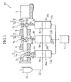
- FIG. 1 is a block diagram of an atomizing process system which includes an atomizing apparatus incorporating a pump member of the present invention.
- FIG. 2 is an enlarged partial cross-section diagram sectioned along II-II line in FIG. 1 when a piston is located on an upper dead center.
- FIG. 3 is an enlarged partial cross-section diagram sectioned along II - II line in FIG. 1 when the piston is located on a bottom dead center.
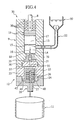
- FIG. 4 is an enlarged partial cross-section diagram sectioned along II - II line in FIG. 1 in which the first modification of the present embodiment is shown.
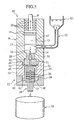
- FIG. 5 is an enlarged partial cross-section diagram sectioned along II - II line in FIG. 1 in which the second modification of the present embodiment is shown.
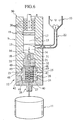
- FIG. 6 is an enlarged partial cross-section diagram sectioned along II - II line in FIG. 1 in which the third modification of the present embodiment is shown.
-
- An embodiment of the present invention is described with reference to FIG.1 to 3.
- As shown in FIG.1, an
atomizing process system 50 comprises a drive device 1, acharge vessel 10, adischarge vessel 11 and atomizingapparatuses - The drive device 1 comprises a
crankshaft 2 and a motor 3. Thecrankshaft 2 has acrank portion 5 rotatably supported to a crankcase bearing 4 andcrankpins crankshaft 2. - The
crankshaft 2 is linked topiston yoke shafts rods crankpins - When the
crankshaft 2 rotates in a direction of an arrow R, thepiston shafts rods piston shafts - The atomizing
apparatuses pump members generator members charge vessel 10 for charging a raw material fluid into the atomizingapparatuses pump members pipe 22. Thedischarge vessel 11 for discharging an atomized raw material product (a sample) is communicated with thegenerator members - Next, a configuration of the atomizing
apparatus 30 will be described in detail. Firstly, a configuration of thepump member 9 will be described and secondly, a configuration of thegenerator member 12 will be described. Here, it noted that the atomizingapparatuses - As shown in FIGS. 2 and 3, the
pump member 9 has thepiston 13, acylinder 17, thepipe 22 and a connectingportion 35. Thecylinder 17 opens at one end thereof. The connectingportion 35 closes the other end of thecylinder 17. Here, it noted that the other end of thecylinder 17 is named a closedend 18. One end ofpiston 13 is integrally linked to thepiston shaft 8 and reciprocally moves inside thecylinder 17 with a rotation of thecrankshaft 2. - A closed
pressure chamber 14 is formed between the other end of thepiston 13 and the closedend 18 of thecylinder 17. Thepiston 13 is provided with two pieces ofpiston packing 19. Thepiston shaft 8 is provided with four pieces of piston shaft packing 20. The piston packing 19 and the piston shaft packing 20 sliding with thepiston 13 inside thecylinder 17 closes thepressure chamber 14. - The connecting
portion 35 is fitted into the other end of thecylinder 17. The connectingportion 35 has a communicatinghole 31 at a center portion thereof. The communicatinghole 31 opens to theclosed end 18 of thepressure chamber 14 at one end (an outlet 16) thereof. The communicatinghole 31 opens to one end of a communicatinghole 32 which is formed into anouter case 23 of thegenerator member 12 at the other end thereof. The communicatinghole 31 is provided with acheck valve 21. Thecheck valve 21 opens and then sends the pressured raw material fluid into thegenerator member 12 when thepiston 13 descends. Thecheck valve 21 closes and then prevents the raw material fluid sent into thegenerator member 12 from flowing back when thepiston 13 ascends. - The
pipe 22 is connected to a side face of thecylinder 17 in order to link thepump member 9 with thecharge vessel 10 therethrough. Thepipe 22 opens to an inner surface of thecylinder 17 at one end (an intake 15) thereof. Thepipe 22 opens to a bottom surface of thecharge vessel 10 at the other end thereof. Thepipe 22 and thecylinder 17 are connected together by screwing a male screw portion threaded on a side surface of thepipe 22 into a female screw portion threaded on the side surface of thecylinder 17. - A reciprocating stroke of the
piston 13 will be described. As shown in FIG. 2, in a case where thepiston 13 ascends from a bottom dead center (a charging stroke), thecheck valve 21 closes and then prevents the raw material fluid sent into thegenerator member 12 from flowing back. The raw material fluid in thecharge vessel 10 is delivered into thepressure chamber 14 through thepipe 22 because theintake 15 opens with the ascent of thepiston 13. - In a case where the
piston 13 descends from an upper dead center (a discharge stroke), the raw material fluid of thepressure chamber 14 flows back into thecharge vessel 10 through thepipe 22 in the first half of the discharge stroke because theintake 15 opens. In the last half of the discharge stroke, as shown in FIG. 3, the raw material fluid pressured in thepressure chamber 14 is sent from theoutlet 16 into thegenerator member 12 because theintake 15 is closed by the side surface of thepiston 13. At the bottom dead center of thepiston 13, since the piston packing 19 and the piston shaft packing 20 locates above theintake 15, the packing is prevented from being damaged by flow pressure of the raw material fluid. - In a conventional pump, since a pipe through which a charge vessel is connected to a pump member is provided with a check valve for charge therein, a raw material fluid of a pressure chamber is prevented from flowing back into the charge vessel in a discharge stroke. On the other hand, in the present invention, since the
intake 15 opens to thepressure chamber 14 until theintake 15 is closed by the side surface of thepiston 13, that is to say, before the last half stroke, the raw material fluid of thepressure chamber 14 flows back into the charge vessel. Although this flow-back reduces packing efficiency of thepump member 9, the flow-back is small in amount because an inside diameter of thepipe 22 is small. Therefore, it slightly influences on the packing efficiency of thepump member 9. Further, it is not necessary to install an agitator in thecharge vessel 10 because the flow-back agitates several raw materials among which specific gravity differs in thecharge vessel 10. Additionally, in the last half of the discharge stroke, the raw material fluid of thepressure chamber 14 is certainly prevented from flowing back into thecharge vessel 10 without depending to the raw material fluids' character because theintake 15 is closed by the side surface of thepiston 13. - Also, it is possible to improve pump efficiency because average velocity of the
piston 13 in upper and lower directions is changed by eccentrically connecting the connecting-rods crankpin - Next, a configuration of the
generator member 12 will be described in detail. As shown in FIG.2 and 3, thegenerator member 12 has theouter case 23, aninner case 24 and anoutlet 28. Amale thread portion 36 formed on a center of an upper end surface of theouter case 23 is screwed into afemale thread portion 37 formed on a center of a bottom end surface of thepump member 9, and thereby thegenerator member 12 is connected to thepump member 9. Further, the communicatinghole 32 is provided to a center portion of themale thread portion 36 of theouter case 23. The pressured raw material fluid is sent into ahollow chamber 25 by allowing the communicatinghole 32 to open to the communicatinghole 31 of the connectingportion 35 at one end thereof and to thehollow chamber 25 at the other end thereof The ceramichollow chamber 25 which closes at one end thereof and opens at the other end thereof is formed inside theouter case 23. Afemale thread portion 38 formed on the other end of thehollow chamber 25 is screwed to amale thread portion 39 of theoutlet 28, and thereby theouter case 23 is connected to theoutlet 28. Further, thehollow chamber 25 accommodates theinner case 24. A bottom end portion of theinner case 24 is inserted into aconcave portion 40 formed on a center of an upper end surface of themale thread portion 39 and having the same diameter of theinner case 24, and thereby theinner case 24 is fixed to theoutlet 28. - A
center passage 27 is formed in theinner case 24 along an axial direction of theinner case 24. A plurality ofhole portions 26 are formed in the side surface of theinner case 24 along a radial direction of theinner case 24. Thehole portions 26 open to thehollow chamber 25 at one end thereof and to thecenter passage 27 at the other end thereof. Thecenter passage 27 closes at one end thereof and opens to an outlet hole of theoutlet 28 at the other end thereof. - For example, the
inner case 24 is a cylindrical body having a diameter of 40 mm and a length of 40 mm. Each of thehole portions 26 has a diameter from 0.1 to 0.4 mm. On the side surface of theinner case 24, theinner case 24 consists of n hole portions 26 (n isform 2 to 8) in the radial direction thereof and m hole portions 26 (m is one or more) in the axial direction thereof. Since theinner case 21 is made of ceramic, thehole portions 26 are easily formed. - A substance included in the pressured raw material fluid is atomized according to a nozzle character of each
hole portion 26. Total volume of thehole portions 26 is much smaller than piston stroke volume (for example, a piston diameter of 40 mm and a stroke length of 40 mm) of thepump member 9. Therefore, pressure applied to the raw material fluid in thehole portions 26 is higher than pressure applied to the raw material fluid in thepump member 9. Namely, the raw material fluid passes through thehole portions 26 at high-speed flow and then the substance included in the raw material fluid is atomized according to the nozzle character of eachhole portion 26. The raw material fluids further crash each other at high-speed in thecenter passage 24 and then the substance included in the crashed raw material fluid is atomized. The atomized raw material (the raw material product) is discharged from the other end of the outlet hole of theoutlet 25 into thedischarge vessel 11. - In a case where a raw material is changed or a blockage in members occurs, it is necessary to from charge to discharge flush out all members which contact with the prior raw material fluid and then check them so as to realize prevention of contamination. However, flushing and checking works are easily performed because the
atomizing apparatus 30 is simply decomposed into anoutlet 28, theinner case 26, theouter case 23, the connectingportion 35, thecheck valve 21, thepipe 22, thecylinder 17 and thepiston 13. - As the first modification of the present embodiment, as shown in FIG. 4, the
inner case 23 may be connected to theoutlet 28 by screwing amale thread portion 41 formed on the center of the bottom end surface of theinner case 23 into afemale thread portion 42 formed on the center of the upper end surface of theoutlet 28. In this case, thehollow chamber 25 opens at an end center of themale thread portion 41, and thereby thehollow chamber 25 is certainly closed and theoutlet 28 is easily detachable from theouter case 23. - As the second modification of the present embodiment, as shown in FIG. 5, the
pump member 9 may be connected to thegenerator member 12 by screwing amale thread portion 43 formed on the center of the bottom end surface of thepump member 9 into afemale thread portion 44 formed on the center of the upper end surface of theouter case 23, in addition to connecting theouter case 23 to theoutlet 28 described in the first modification. In this case, one part of the connectingportion 35 is fitted to a center portion of themale thread portion 43 of thepump member 9, and the communicatinghole 32 opens to a center of a bottom surface of thefemale thread portion 44 at one end thereof. Further, thefemale thread portion 44 of theouter case 23 is provided with packing 33 at a bottom surface thereof, and thereby a user can easily grasp theouter case 23 because theouter case 23 is longer than the outer case of the first modification along the an axial direction thereof. - As the third embodiment of the present embodiment, a connection of the
pump member 9 and thegenerator member 12 may be employed as shown in FIG. 6, in addition to connecting theouter case 23 to theoutlet 28 described in the first embodiment. Afemale thread portion 45 is formed on the center of the bottom end surface of thepump member 9. Aconcave portion 47 having the same diameter of theinner case 24 is formed on a center of a bottom surface of thefemale thread portion 45. Agroove portion 48 is formed on a center of a bottom surface of theconcave portion 47. Communicatingholes 49 open to thehollow chamber 25 at one end thereof and to both ends of thegroove portion 48 at the other end thereof. The communicatinghole 31 of the connectingportion 35 opens to a center of a bottom surface of thegroove portion 48 at the other end thereof. Thereby, the pressured raw material fluid is sent from thepressure chamber 14 into thehollow chamber 25 through the communicatinghole 31, thegroove 48 and the communicating holes 49. - The
male thread portions outer case 36 and thehollow chamber 25 opens to centers of end faces of themale thread portions outer case 23 is connected to thepump member 9 by screwing themale thread portion 46 of theouter case 23 into thefemale thread portion 45 of thepump member 9. At this time, thehollow chamber 25 accommodates both end portions of theinner case 24 sandwiched between theconcave portions hollow chamber 25 certainly closes between thepump member 9 and theoutlet 28. - As the fourth modification of the present embodiment, the
cylinder 17 may be fixedly provided with packing in thepump member 9. - As the fifth modification of the preset embodiment, a power mechanism such as an electrohydraulic motor or a pneumatic motor and a manumotive mechanism may be employed as the motor rotating the crankshaft, and a drive mechanism controlled by an electrical operation may be employed as a crank mechanism including the crankshaft.
- As the sixth modification of the present embodiment, in the
atomizing process system 50, theatomizing apparatuses charge vessel 10 and thedischarge vessel 11 may be disposed above and below theatomizing apparatuses - An atomizing apparatus of the present invention allows a raw material fluid to flow back from a pressure chamber into a charge vessel in the first half of a discharge stroke and not to flow back from the pressure chamber into the charge vessel in the last half of the discharge stroke. Also, the atomizing apparatus of the present invention allows a flushing work to be easily performed because a constructional element is simplified.
Claims (11)
- A substance-atomizing apparatus comprising:wherein a pressure chamber is formed between the piston and a closed end of the cylinder,a pump member having:a cylinder opening at one end thereof and closing at the other end thereof;a pipe through which a raw material fluid is introduced from a charge vessel into the cylinder; anda piston reciprocally moved by a drive device in the cylinder to pressurize the raw material fluid in the cylinder; anda generator member inserting the raw material fluid pressurized in the pump member into a hole portion formed therein to atomize a substance included in the raw material fluid according to a nozzle character of the hole portion,
an intake to which the pipe opens at one end thereof is formed on a cylinder side surface of the pressure chamber,
an outlet is formed on the closed end of the cylinder,
the outlet is closed and the raw material fluid is received from the charge vessel into the pressure chamber through the intake in a first stroke of the piston,
the raw material fluid is sent from the pressure chamber into the charge vessel through the intake in the first half of a second stroke of the piston,
the intake is directly closed by a side surface of the piston and the raw material fluid is sent from the pressure chamber into the generator member through the outlet in the last half of the second stroke of the piston. - The substance-atomizing apparatus according to claim 1, wherein the pump member has a check valve for opening and closing the outlet.
- The substance-atomizing apparatus according to claim 1, wherein the generator member has an outlet portion having an outlet hole for sending to a discharge vessel the raw material fluid including the atomized substance therein.
- The substance-atomizing apparatus according to claim 3, wherein the generator member has;
an outer case connected to the cylinder at one end thereof and to the outlet portion at the other end thereof; and
an inner case accommodated by the outer case and fixed to the outlet portion at one end thereof,
a hollow chamber is formed between the outer case and the inner case,
a communicating hole for communicating the pressure chamber with the hollow chamber through the outlet is formed at one end the outer case,
a center passage which closes at one end thereof and opens to the hollow chamber at the other end thereof is formed in the inner case,
a plurality of the hole portions which each opens to the center passage at one end thereof and to the hollow chamber at the other end thereof are formed on a side surface of the inner case. - The substance-atomizing apparatus according to claim 4, wherein the inner case is made of a ceramic.
- The substance-atomizing apparatus according to claim 4, wherein the inner case is fixed to a concave portion formed on an end face of the outlet portion, at one end thereof.
- The substance-atomizing apparatus according to claim 4, wherein the inner case is fixed to a first concave portion formed on an end face of the outlet portion, at one end thereof and to a second concave portion formed on an end face of the cylinder, at the other end thereof.
- The substance-atomizing apparatus according to claim 4, wherein the outer case is connected to the cylinder by screwing a male thread portion threaded on one end of the outer case into a female thread portion threaded on the cylinder.
- The substance-atomizing apparatus according to calim4, wherein the outer case is connected to the cylinder by screwing a male thread portion threaded on the cylinder into a female thread portion threaded on one end of the outer case.
- The substance-atomizing apparatus according to claim 4, wherein the outer case is connected to the outlet portion by screwing a male thread portion threaded on the outlet portion into a female thread portion threaded on the other end of the outer case.
- The substance-atomizing apparatus according to claim 4, wherein the outer case is connected to the outlet portion by screwing a male thread portion threaded on the other end of the outer case into a female thread portion threaded on the outlet portion.
Applications Claiming Priority (3)
| Application Number | Priority Date | Filing Date | Title |
|---|---|---|---|
| JP2002272049 | 2002-09-18 | ||
| JP2002272049 | 2002-09-18 | ||
| PCT/JP2003/011893 WO2004026481A1 (en) | 2002-09-18 | 2003-09-18 | Substance-atomizing apparatus |
Publications (3)
| Publication Number | Publication Date |
|---|---|
| EP1550508A1 true EP1550508A1 (en) | 2005-07-06 |
| EP1550508A4 EP1550508A4 (en) | 2009-12-09 |
| EP1550508B1 EP1550508B1 (en) | 2011-07-13 |
Family
ID=32024895
Family Applications (1)
| Application Number | Title | Priority Date | Filing Date |
|---|---|---|---|
| EP03797656A Expired - Lifetime EP1550508B1 (en) | 2002-09-18 | 2003-09-18 | Substance-atomizing apparatus |
Country Status (7)
| Country | Link |
|---|---|
| US (1) | US7175117B2 (en) |
| EP (1) | EP1550508B1 (en) |
| JP (1) | JP4121499B2 (en) |
| CN (1) | CN1305576C (en) |
| AU (1) | AU2003264487A1 (en) |
| TW (1) | TWI276464B (en) |
| WO (1) | WO2004026481A1 (en) |
Cited By (2)
| Publication number | Priority date | Publication date | Assignee | Title |
|---|---|---|---|---|
| EP1616618A3 (en) * | 2004-07-13 | 2006-11-22 | Shigeo Ando | High pressure homogenizing apparatus and method thereof |
| CN111677642A (en) * | 2020-06-23 | 2020-09-18 | 追觅科技(上海)有限公司 | Swing pump, self-mixing foaming device and hand washing device having the same |
Families Citing this family (7)
| Publication number | Priority date | Publication date | Assignee | Title |
|---|---|---|---|---|
| JP4707342B2 (en) * | 2004-07-20 | 2011-06-22 | 株式会社東海 | Substance atomization equipment |
| JP4759270B2 (en) * | 2005-01-11 | 2011-08-31 | 日本特殊陶業株式会社 | Control method of atomizer |
| JP2010279904A (en) * | 2009-06-04 | 2010-12-16 | Tomihisa Naito | Atomizing apparatus and atomization system |
| CN103721629A (en) * | 2013-12-31 | 2014-04-16 | 陕西万源生物农业科技有限公司 | Particle pelletizing device |
| CN109351443B (en) * | 2018-12-02 | 2024-02-27 | 北京协同创新食品科技有限公司 | High-pressure jet nozzle and high-pressure jet crushing device using same |
| US20230149866A1 (en) * | 2020-04-02 | 2023-05-18 | YOSHIDA WORKS PRO Co., Ltd. | Wet atomization apparatus and method |
| JP7699189B2 (en) * | 2023-11-17 | 2025-06-26 | 中越パルプ工業株式会社 | Microfabrication processing equipment |
Family Cites Families (9)
| Publication number | Priority date | Publication date | Assignee | Title |
|---|---|---|---|---|
| JPS5024737B1 (en) * | 1970-09-04 | 1975-08-18 | ||
| CN1083179A (en) * | 1992-10-26 | 1994-03-02 | 何贵庭 | Atomizing pump |
| JP2527297B2 (en) * | 1993-10-01 | 1996-08-21 | ナノマイザー株式会社 | Material atomizer |
| US5984519A (en) * | 1996-12-26 | 1999-11-16 | Genus Corporation | Fine particle producing devices |
| US6045068A (en) * | 1997-12-16 | 2000-04-04 | Ashbrook; Clifford L. | Method for treating cement slurries |
| US6318649B1 (en) * | 1999-10-06 | 2001-11-20 | Cornerstone Technologies, Llc | Method of creating ultra-fine particles of materials using a high-pressure mill |
| JP3423915B2 (en) * | 2000-03-27 | 2003-07-07 | エス・ジーエンジニアリング株式会社 | Plunger type pump device |
| JP3435387B2 (en) * | 2000-06-16 | 2003-08-11 | エス・ジーエンジニアリング株式会社 | Atomizer for substance |
| JP5024737B2 (en) * | 2010-10-15 | 2012-09-12 | 横浜ゴム株式会社 | Long material take-up drum |
-
2003
- 2003-09-18 CN CNB038221195A patent/CN1305576C/en not_active Expired - Fee Related
- 2003-09-18 JP JP2004537595A patent/JP4121499B2/en not_active Expired - Fee Related
- 2003-09-18 US US10/528,202 patent/US7175117B2/en not_active Expired - Fee Related
- 2003-09-18 WO PCT/JP2003/011893 patent/WO2004026481A1/en not_active Ceased
- 2003-09-18 AU AU2003264487A patent/AU2003264487A1/en not_active Abandoned
- 2003-09-18 EP EP03797656A patent/EP1550508B1/en not_active Expired - Lifetime
- 2003-09-18 TW TW092125782A patent/TWI276464B/en not_active IP Right Cessation
Non-Patent Citations (2)
| Title |
|---|
| No further relevant documents disclosed * |
| See also references of WO2004026481A1 * |
Cited By (5)
| Publication number | Priority date | Publication date | Assignee | Title |
|---|---|---|---|---|
| EP1616618A3 (en) * | 2004-07-13 | 2006-11-22 | Shigeo Ando | High pressure homogenizing apparatus and method thereof |
| US7413135B2 (en) | 2004-07-13 | 2008-08-19 | Shigeo Ando | High pressure homogenizing apparatus and method thereof |
| US7530511B2 (en) | 2004-07-13 | 2009-05-12 | Shigeo Ando | High pressure homogenizing apparatus and method thereof |
| KR100920786B1 (en) * | 2004-07-13 | 2009-10-08 | 시게오 안도 | High pressure homogenizing apparatus and method thereof |
| CN111677642A (en) * | 2020-06-23 | 2020-09-18 | 追觅科技(上海)有限公司 | Swing pump, self-mixing foaming device and hand washing device having the same |
Also Published As
| Publication number | Publication date |
|---|---|
| EP1550508A4 (en) | 2009-12-09 |
| CN1305576C (en) | 2007-03-21 |
| AU2003264487A1 (en) | 2004-04-08 |
| US20060131451A1 (en) | 2006-06-22 |
| TWI276464B (en) | 2007-03-21 |
| JP4121499B2 (en) | 2008-07-23 |
| TW200413088A (en) | 2004-08-01 |
| HK1078286A1 (en) | 2006-03-10 |
| CN1681598A (en) | 2005-10-12 |
| JPWO2004026481A1 (en) | 2006-01-12 |
| EP1550508B1 (en) | 2011-07-13 |
| WO2004026481A1 (en) | 2004-04-01 |
| US7175117B2 (en) | 2007-02-13 |
Similar Documents
| Publication | Publication Date | Title |
|---|---|---|
| EP1550508B1 (en) | Substance-atomizing apparatus | |
| US6364639B1 (en) | Pump | |
| US3712759A (en) | Lubricating system for multiple piston compressor units and driven parts thereof | |
| KR20100015960A (en) | Air-operated pump | |
| CN100362233C (en) | Multi-component metering & dispensing system | |
| US6983682B2 (en) | Method and device at a hydrodynamic pump piston | |
| HK1078286B (en) | Substance-atomizing apparatus | |
| US4457670A (en) | Methods and apparatus for pumping compressible dynamoelectric machine lubricant material | |
| KR101113797B1 (en) | The power sprayer | |
| KR101900222B1 (en) | Manual hydraulic equipment using handle | |
| CA1317814C (en) | Plunger pump | |
| US5709536A (en) | Hydro mechanical packingless pump and liquid spray system | |
| CN117803548A (en) | Continuous piston pump and discharging method thereof | |
| KR101747691B1 (en) | High-pressure sprayer | |
| GB2185291A (en) | Pump unit of an apparatus for applying coatings | |
| JP2009013898A (en) | Plunger pump | |
| US4413957A (en) | Portable, hand held, high pressure pump | |
| CA2535822A1 (en) | Apparatuses and methods for pumping fluids | |
| US1898815A (en) | Lubricator pump | |
| JP3314604B2 (en) | Multiple reciprocating pump device | |
| US20130139682A1 (en) | Single Sided, Dual Plunger Pump | |
| JP2010279904A (en) | Atomizing apparatus and atomization system | |
| CA2052201A1 (en) | Positive displacement pump with rotating reciprocating piston and improved pulsation dampening | |
| JPS6375367A (en) | Pressure-feed method for multiple reciprocating pump and device thereof | |
| MXPA00000939A (en) | Two stage oil free air compressor |
Legal Events
| Date | Code | Title | Description |
|---|---|---|---|
| PUAI | Public reference made under article 153(3) epc to a published international application that has entered the european phase |
Free format text: ORIGINAL CODE: 0009012 |
|
| 17P | Request for examination filed |
Effective date: 20050408 |
|
| AK | Designated contracting states |
Kind code of ref document: A1 Designated state(s): AT BE BG CH CY CZ DE DK EE ES FI FR GB GR HU IE IT LI LU MC NL PT RO SE SI SK TR |
|
| AX | Request for extension of the european patent |
Extension state: AL LT LV MK |
|
| DAX | Request for extension of the european patent (deleted) | ||
| RBV | Designated contracting states (corrected) |
Designated state(s): DE FR GB |
|
| REG | Reference to a national code |
Ref country code: HK Ref legal event code: DE Ref document number: 1078286 Country of ref document: HK |
|
| A4 | Supplementary search report drawn up and despatched |
Effective date: 20091110 |
|
| 17Q | First examination report despatched |
Effective date: 20100708 |
|
| GRAP | Despatch of communication of intention to grant a patent |
Free format text: ORIGINAL CODE: EPIDOSNIGR1 |
|
| GRAS | Grant fee paid |
Free format text: ORIGINAL CODE: EPIDOSNIGR3 |
|
| GRAA | (expected) grant |
Free format text: ORIGINAL CODE: 0009210 |
|
| AK | Designated contracting states |
Kind code of ref document: B1 Designated state(s): DE FR GB |
|
| REG | Reference to a national code |
Ref country code: GB Ref legal event code: FG4D |
|
| REG | Reference to a national code |
Ref country code: DE Ref legal event code: R096 Ref document number: 60337698 Country of ref document: DE Effective date: 20110901 |
|
| REG | Reference to a national code |
Ref country code: HK Ref legal event code: GR Ref document number: 1078286 Country of ref document: HK |
|
| PLBE | No opposition filed within time limit |
Free format text: ORIGINAL CODE: 0009261 |
|
| STAA | Information on the status of an ep patent application or granted ep patent |
Free format text: STATUS: NO OPPOSITION FILED WITHIN TIME LIMIT |
|
| 26N | No opposition filed |
Effective date: 20120416 |
|
| REG | Reference to a national code |
Ref country code: DE Ref legal event code: R097 Ref document number: 60337698 Country of ref document: DE Effective date: 20120416 |
|
| REG | Reference to a national code |
Ref country code: DE Ref legal event code: R082 Ref document number: 60337698 Country of ref document: DE Representative=s name: HOFFMANN - EITLE PATENT- UND RECHTSANWAELTE PA, DE |
|
| REG | Reference to a national code |
Ref country code: DE Ref legal event code: R081 Ref document number: 60337698 Country of ref document: DE Owner name: NAITO, SYOUKO, KANAGAWA, JP Free format text: FORMER OWNER: SYOUKO NAITO,TOMIHISA NAITO, TOKAI CORP., , JP Effective date: 20141125 Ref country code: DE Ref legal event code: R082 Ref document number: 60337698 Country of ref document: DE Representative=s name: HOFFMANN - EITLE PATENT- UND RECHTSANWAELTE PA, DE Effective date: 20141125 Ref country code: DE Ref legal event code: R081 Ref document number: 60337698 Country of ref document: DE Owner name: NAITO, TOMIHISA, KANAGAWA, JP Free format text: FORMER OWNER: SYOUKO NAITO,TOMIHISA NAITO, TOKAI CORP., , JP Effective date: 20141125 Ref country code: DE Ref legal event code: R081 Ref document number: 60337698 Country of ref document: DE Owner name: NAITO, TOMIHISA, KANAGAWA, JP Free format text: FORMER OWNER: TOMIHISA NAITO,SYOUKO NAITO, TOKAI CORP., , JP Effective date: 20110713 Ref country code: DE Ref legal event code: R081 Ref document number: 60337698 Country of ref document: DE Owner name: NAITO, SYOUKO, KANAGAWA, JP Free format text: FORMER OWNER: TOMIHISA NAITO,SYOUKO NAITO, TOKAI CORP., , JP Effective date: 20110713 Ref country code: GB Ref legal event code: 732E Free format text: REGISTERED BETWEEN 20141204 AND 20141211 Ref country code: DE Ref legal event code: R081 Ref document number: 60337698 Country of ref document: DE Owner name: NAITO, TOMIHISA, KANAGAWA, JP Free format text: FORMER OWNERS: NAITO, SYOUKO, KANAGAWA, ODAWARA-SHI, JP; NAITO, TOMIHISA, KANAGAWA, ODAWARA-SHI, JP; TOKAI CORP., TOKIO/TOKYO, JP Effective date: 20141125 Ref country code: DE Ref legal event code: R081 Ref document number: 60337698 Country of ref document: DE Owner name: NAITO, TOMIHISA, KANAGAWA, JP Free format text: FORMER OWNERS: NAITO, TOMIHISA, ODAWARA, KANAGAWA, JP; NAITO, SYOUKO, ODAWARA, KANAGAWA, JP; TOKAI CORP., TOKIO/TOKYO, JP Effective date: 20110713 Ref country code: DE Ref legal event code: R081 Ref document number: 60337698 Country of ref document: DE Owner name: NAITO, SYOUKO, KANAGAWA, JP Free format text: FORMER OWNERS: NAITO, SYOUKO, KANAGAWA, ODAWARA-SHI, JP; NAITO, TOMIHISA, KANAGAWA, ODAWARA-SHI, JP; TOKAI CORP., TOKIO/TOKYO, JP Effective date: 20141125 Ref country code: DE Ref legal event code: R081 Ref document number: 60337698 Country of ref document: DE Owner name: NAITO, SYOUKO, KANAGAWA, JP Free format text: FORMER OWNERS: NAITO, TOMIHISA, ODAWARA, KANAGAWA, JP; NAITO, SYOUKO, ODAWARA, KANAGAWA, JP; TOKAI CORP., TOKIO/TOKYO, JP Effective date: 20110713 |
|
| REG | Reference to a national code |
Ref country code: FR Ref legal event code: TQ Owner name: NAITO, TOMIHISA, JP Effective date: 20150107 Ref country code: FR Ref legal event code: TQ Owner name: NAITO, SYOUKO, JP Effective date: 20150107 |
|
| REG | Reference to a national code |
Ref country code: FR Ref legal event code: PLFP Year of fee payment: 13 |
|
| REG | Reference to a national code |
Ref country code: FR Ref legal event code: PLFP Year of fee payment: 14 |
|
| REG | Reference to a national code |
Ref country code: FR Ref legal event code: PLFP Year of fee payment: 15 |
|
| PGFP | Annual fee paid to national office [announced via postgrant information from national office to epo] |
Ref country code: FR Payment date: 20171219 Year of fee payment: 15 Ref country code: DE Payment date: 20171130 Year of fee payment: 15 |
|
| PGFP | Annual fee paid to national office [announced via postgrant information from national office to epo] |
Ref country code: GB Payment date: 20171130 Year of fee payment: 15 |
|
| REG | Reference to a national code |
Ref country code: DE Ref legal event code: R119 Ref document number: 60337698 Country of ref document: DE |
|
| GBPC | Gb: european patent ceased through non-payment of renewal fee |
Effective date: 20180918 |
|
| PG25 | Lapsed in a contracting state [announced via postgrant information from national office to epo] |
Ref country code: DE Free format text: LAPSE BECAUSE OF NON-PAYMENT OF DUE FEES Effective date: 20190402 |
|
| PG25 | Lapsed in a contracting state [announced via postgrant information from national office to epo] |
Ref country code: FR Free format text: LAPSE BECAUSE OF NON-PAYMENT OF DUE FEES Effective date: 20180930 |
|
| PG25 | Lapsed in a contracting state [announced via postgrant information from national office to epo] |
Ref country code: GB Free format text: LAPSE BECAUSE OF NON-PAYMENT OF DUE FEES Effective date: 20180918 |