EP1550419A2 - Tethered implant systems with fastener for mounting on an articulation surface of an orthopedic joint - Google Patents
Tethered implant systems with fastener for mounting on an articulation surface of an orthopedic joint Download PDFInfo
- Publication number
- EP1550419A2 EP1550419A2 EP04030618A EP04030618A EP1550419A2 EP 1550419 A2 EP1550419 A2 EP 1550419A2 EP 04030618 A EP04030618 A EP 04030618A EP 04030618 A EP04030618 A EP 04030618A EP 1550419 A2 EP1550419 A2 EP 1550419A2
- Authority
- EP
- European Patent Office
- Prior art keywords
- implant
- recited
- line
- bone
- implant system
- Prior art date
- Legal status (The legal status is an assumption and is not a legal conclusion. Google has not performed a legal analysis and makes no representation as to the accuracy of the status listed.)
- Granted
Links
- 0 *C1C*CC1 Chemical compound *C1C*CC1 0.000 description 2
Images


Classifications
-
- A—HUMAN NECESSITIES
- A61—MEDICAL OR VETERINARY SCIENCE; HYGIENE
- A61B—DIAGNOSIS; SURGERY; IDENTIFICATION
- A61B17/00—Surgical instruments, devices or methods
- A61B17/56—Surgical instruments or methods for treatment of bones or joints; Devices specially adapted therefor
- A61B17/58—Surgical instruments or methods for treatment of bones or joints; Devices specially adapted therefor for osteosynthesis, e.g. bone plates, screws or setting implements
- A61B17/88—Osteosynthesis instruments; Methods or means for implanting or extracting internal or external fixation devices
- A61B17/8869—Tensioning devices
-
- A—HUMAN NECESSITIES
- A61—MEDICAL OR VETERINARY SCIENCE; HYGIENE
- A61B—DIAGNOSIS; SURGERY; IDENTIFICATION
- A61B17/00—Surgical instruments, devices or methods
- A61B17/14—Surgical saws
- A61B17/15—Guides therefor
- A61B17/154—Guides therefor for preparing bone for knee prosthesis
- A61B17/157—Cutting tibia
-
- A—HUMAN NECESSITIES
- A61—MEDICAL OR VETERINARY SCIENCE; HYGIENE
- A61B—DIAGNOSIS; SURGERY; IDENTIFICATION
- A61B17/00—Surgical instruments, devices or methods
- A61B17/16—Instruments for performing osteoclasis; Drills or chisels for bones; Trepans
- A61B17/1659—Surgical rasps, files, planes, or scrapers
-
- A—HUMAN NECESSITIES
- A61—MEDICAL OR VETERINARY SCIENCE; HYGIENE
- A61B—DIAGNOSIS; SURGERY; IDENTIFICATION
- A61B17/00—Surgical instruments, devices or methods
- A61B17/16—Instruments for performing osteoclasis; Drills or chisels for bones; Trepans
- A61B17/1662—Instruments for performing osteoclasis; Drills or chisels for bones; Trepans for particular parts of the body
- A61B17/1675—Instruments for performing osteoclasis; Drills or chisels for bones; Trepans for particular parts of the body for the knee
-
- A—HUMAN NECESSITIES
- A61—MEDICAL OR VETERINARY SCIENCE; HYGIENE
- A61B—DIAGNOSIS; SURGERY; IDENTIFICATION
- A61B17/00—Surgical instruments, devices or methods
- A61B17/16—Instruments for performing osteoclasis; Drills or chisels for bones; Trepans
- A61B17/17—Guides or aligning means for drills, mills, pins or wires
- A61B17/1714—Guides or aligning means for drills, mills, pins or wires for applying tendons or ligaments
-
- A—HUMAN NECESSITIES
- A61—MEDICAL OR VETERINARY SCIENCE; HYGIENE
- A61B—DIAGNOSIS; SURGERY; IDENTIFICATION
- A61B17/00—Surgical instruments, devices or methods
- A61B17/16—Instruments for performing osteoclasis; Drills or chisels for bones; Trepans
- A61B17/17—Guides or aligning means for drills, mills, pins or wires
- A61B17/1735—Guides or aligning means for drills, mills, pins or wires for rasps or chisels
-
- A—HUMAN NECESSITIES
- A61—MEDICAL OR VETERINARY SCIENCE; HYGIENE
- A61B—DIAGNOSIS; SURGERY; IDENTIFICATION
- A61B17/00—Surgical instruments, devices or methods
- A61B17/16—Instruments for performing osteoclasis; Drills or chisels for bones; Trepans
- A61B17/17—Guides or aligning means for drills, mills, pins or wires
- A61B17/1739—Guides or aligning means for drills, mills, pins or wires specially adapted for particular parts of the body
- A61B17/1764—Guides or aligning means for drills, mills, pins or wires specially adapted for particular parts of the body for the knee
-
- A—HUMAN NECESSITIES
- A61—MEDICAL OR VETERINARY SCIENCE; HYGIENE
- A61B—DIAGNOSIS; SURGERY; IDENTIFICATION
- A61B17/00—Surgical instruments, devices or methods
- A61B17/56—Surgical instruments or methods for treatment of bones or joints; Devices specially adapted therefor
- A61B17/58—Surgical instruments or methods for treatment of bones or joints; Devices specially adapted therefor for osteosynthesis, e.g. bone plates, screws or setting implements
- A61B17/88—Osteosynthesis instruments; Methods or means for implanting or extracting internal or external fixation devices
- A61B17/8861—Apparatus for manipulating flexible wires or straps
-
- A—HUMAN NECESSITIES
- A61—MEDICAL OR VETERINARY SCIENCE; HYGIENE
- A61B—DIAGNOSIS; SURGERY; IDENTIFICATION
- A61B17/00—Surgical instruments, devices or methods
- A61B17/56—Surgical instruments or methods for treatment of bones or joints; Devices specially adapted therefor
- A61B17/58—Surgical instruments or methods for treatment of bones or joints; Devices specially adapted therefor for osteosynthesis, e.g. bone plates, screws or setting implements
- A61B17/88—Osteosynthesis instruments; Methods or means for implanting or extracting internal or external fixation devices
- A61B17/8875—Screwdrivers, spanners or wrenches
-
- A—HUMAN NECESSITIES
- A61—MEDICAL OR VETERINARY SCIENCE; HYGIENE
- A61F—FILTERS IMPLANTABLE INTO BLOOD VESSELS; PROSTHESES; DEVICES PROVIDING PATENCY TO, OR PREVENTING COLLAPSING OF, TUBULAR STRUCTURES OF THE BODY, e.g. STENTS; ORTHOPAEDIC, NURSING OR CONTRACEPTIVE DEVICES; FOMENTATION; TREATMENT OR PROTECTION OF EYES OR EARS; BANDAGES, DRESSINGS OR ABSORBENT PADS; FIRST-AID KITS
- A61F2/00—Filters implantable into blood vessels; Prostheses, i.e. artificial substitutes or replacements for parts of the body; Appliances for connecting them with the body; Devices providing patency to, or preventing collapsing of, tubular structures of the body, e.g. stents
- A61F2/02—Prostheses implantable into the body
- A61F2/30—Joints
- A61F2/32—Joints for the hip
- A61F2/36—Femoral heads ; Femoral endoprostheses
- A61F2/3601—Femoral heads ; Femoral endoprostheses for replacing only the epiphyseal or metaphyseal parts of the femur, e.g. endoprosthetic femoral heads or necks directly fixed to the natural femur by internal fixation devices
- A61F2/3603—Femoral heads ; Femoral endoprostheses for replacing only the epiphyseal or metaphyseal parts of the femur, e.g. endoprosthetic femoral heads or necks directly fixed to the natural femur by internal fixation devices implanted without ablation of the whole natural femoral head
-
- A—HUMAN NECESSITIES
- A61—MEDICAL OR VETERINARY SCIENCE; HYGIENE
- A61F—FILTERS IMPLANTABLE INTO BLOOD VESSELS; PROSTHESES; DEVICES PROVIDING PATENCY TO, OR PREVENTING COLLAPSING OF, TUBULAR STRUCTURES OF THE BODY, e.g. STENTS; ORTHOPAEDIC, NURSING OR CONTRACEPTIVE DEVICES; FOMENTATION; TREATMENT OR PROTECTION OF EYES OR EARS; BANDAGES, DRESSINGS OR ABSORBENT PADS; FIRST-AID KITS
- A61F2/00—Filters implantable into blood vessels; Prostheses, i.e. artificial substitutes or replacements for parts of the body; Appliances for connecting them with the body; Devices providing patency to, or preventing collapsing of, tubular structures of the body, e.g. stents
- A61F2/02—Prostheses implantable into the body
- A61F2/30—Joints
- A61F2/38—Joints for elbows or knees
-
- A—HUMAN NECESSITIES
- A61—MEDICAL OR VETERINARY SCIENCE; HYGIENE
- A61F—FILTERS IMPLANTABLE INTO BLOOD VESSELS; PROSTHESES; DEVICES PROVIDING PATENCY TO, OR PREVENTING COLLAPSING OF, TUBULAR STRUCTURES OF THE BODY, e.g. STENTS; ORTHOPAEDIC, NURSING OR CONTRACEPTIVE DEVICES; FOMENTATION; TREATMENT OR PROTECTION OF EYES OR EARS; BANDAGES, DRESSINGS OR ABSORBENT PADS; FIRST-AID KITS
- A61F2/00—Filters implantable into blood vessels; Prostheses, i.e. artificial substitutes or replacements for parts of the body; Appliances for connecting them with the body; Devices providing patency to, or preventing collapsing of, tubular structures of the body, e.g. stents
- A61F2/02—Prostheses implantable into the body
- A61F2/30—Joints
- A61F2/40—Joints for shoulders
- A61F2/4003—Replacing only the epiphyseal or metaphyseal parts of the humerus, i.e. endoprosthesis not comprising an entire humeral shaft
-
- A—HUMAN NECESSITIES
- A61—MEDICAL OR VETERINARY SCIENCE; HYGIENE
- A61F—FILTERS IMPLANTABLE INTO BLOOD VESSELS; PROSTHESES; DEVICES PROVIDING PATENCY TO, OR PREVENTING COLLAPSING OF, TUBULAR STRUCTURES OF THE BODY, e.g. STENTS; ORTHOPAEDIC, NURSING OR CONTRACEPTIVE DEVICES; FOMENTATION; TREATMENT OR PROTECTION OF EYES OR EARS; BANDAGES, DRESSINGS OR ABSORBENT PADS; FIRST-AID KITS
- A61F2/00—Filters implantable into blood vessels; Prostheses, i.e. artificial substitutes or replacements for parts of the body; Appliances for connecting them with the body; Devices providing patency to, or preventing collapsing of, tubular structures of the body, e.g. stents
- A61F2/02—Prostheses implantable into the body
- A61F2/30—Joints
- A61F2/42—Joints for wrists or ankles; for hands, e.g. fingers; for feet, e.g. toes
- A61F2/4202—Joints for wrists or ankles; for hands, e.g. fingers; for feet, e.g. toes for ankles
-
- A—HUMAN NECESSITIES
- A61—MEDICAL OR VETERINARY SCIENCE; HYGIENE
- A61B—DIAGNOSIS; SURGERY; IDENTIFICATION
- A61B17/00—Surgical instruments, devices or methods
- A61B17/14—Surgical saws
- A61B17/15—Guides therefor
-
- A—HUMAN NECESSITIES
- A61—MEDICAL OR VETERINARY SCIENCE; HYGIENE
- A61B—DIAGNOSIS; SURGERY; IDENTIFICATION
- A61B17/00—Surgical instruments, devices or methods
- A61B17/16—Instruments for performing osteoclasis; Drills or chisels for bones; Trepans
- A61B17/1662—Instruments for performing osteoclasis; Drills or chisels for bones; Trepans for particular parts of the body
- A61B17/1664—Instruments for performing osteoclasis; Drills or chisels for bones; Trepans for particular parts of the body for the hip
-
- A—HUMAN NECESSITIES
- A61—MEDICAL OR VETERINARY SCIENCE; HYGIENE
- A61B—DIAGNOSIS; SURGERY; IDENTIFICATION
- A61B17/00—Surgical instruments, devices or methods
- A61B17/16—Instruments for performing osteoclasis; Drills or chisels for bones; Trepans
- A61B17/1662—Instruments for performing osteoclasis; Drills or chisels for bones; Trepans for particular parts of the body
- A61B17/1682—Instruments for performing osteoclasis; Drills or chisels for bones; Trepans for particular parts of the body for the foot or ankle
-
- A—HUMAN NECESSITIES
- A61—MEDICAL OR VETERINARY SCIENCE; HYGIENE
- A61B—DIAGNOSIS; SURGERY; IDENTIFICATION
- A61B17/00—Surgical instruments, devices or methods
- A61B17/16—Instruments for performing osteoclasis; Drills or chisels for bones; Trepans
- A61B17/1662—Instruments for performing osteoclasis; Drills or chisels for bones; Trepans for particular parts of the body
- A61B17/1684—Instruments for performing osteoclasis; Drills or chisels for bones; Trepans for particular parts of the body for the shoulder
-
- A—HUMAN NECESSITIES
- A61—MEDICAL OR VETERINARY SCIENCE; HYGIENE
- A61B—DIAGNOSIS; SURGERY; IDENTIFICATION
- A61B17/00—Surgical instruments, devices or methods
- A61B17/56—Surgical instruments or methods for treatment of bones or joints; Devices specially adapted therefor
- A61B17/58—Surgical instruments or methods for treatment of bones or joints; Devices specially adapted therefor for osteosynthesis, e.g. bone plates, screws or setting implements
- A61B17/68—Internal fixation devices, including fasteners and spinal fixators, even if a part thereof projects from the skin
- A61B17/84—Fasteners therefor or fasteners being internal fixation devices
- A61B17/842—Flexible wires, bands or straps
-
- A—HUMAN NECESSITIES
- A61—MEDICAL OR VETERINARY SCIENCE; HYGIENE
- A61B—DIAGNOSIS; SURGERY; IDENTIFICATION
- A61B17/00—Surgical instruments, devices or methods
- A61B17/56—Surgical instruments or methods for treatment of bones or joints; Devices specially adapted therefor
- A61B17/58—Surgical instruments or methods for treatment of bones or joints; Devices specially adapted therefor for osteosynthesis, e.g. bone plates, screws or setting implements
- A61B17/88—Osteosynthesis instruments; Methods or means for implanting or extracting internal or external fixation devices
- A61B17/8897—Guide wires or guide pins
-
- A—HUMAN NECESSITIES
- A61—MEDICAL OR VETERINARY SCIENCE; HYGIENE
- A61B—DIAGNOSIS; SURGERY; IDENTIFICATION
- A61B17/00—Surgical instruments, devices or methods
- A61B17/16—Instruments for performing osteoclasis; Drills or chisels for bones; Trepans
- A61B2017/1602—Mills
-
- A—HUMAN NECESSITIES
- A61—MEDICAL OR VETERINARY SCIENCE; HYGIENE
- A61F—FILTERS IMPLANTABLE INTO BLOOD VESSELS; PROSTHESES; DEVICES PROVIDING PATENCY TO, OR PREVENTING COLLAPSING OF, TUBULAR STRUCTURES OF THE BODY, e.g. STENTS; ORTHOPAEDIC, NURSING OR CONTRACEPTIVE DEVICES; FOMENTATION; TREATMENT OR PROTECTION OF EYES OR EARS; BANDAGES, DRESSINGS OR ABSORBENT PADS; FIRST-AID KITS
- A61F2/00—Filters implantable into blood vessels; Prostheses, i.e. artificial substitutes or replacements for parts of the body; Appliances for connecting them with the body; Devices providing patency to, or preventing collapsing of, tubular structures of the body, e.g. stents
- A61F2/02—Prostheses implantable into the body
- A61F2/30—Joints
- A61F2/30721—Accessories
- A61F2/30749—Fixation appliances for connecting prostheses to the body
-
- A—HUMAN NECESSITIES
- A61—MEDICAL OR VETERINARY SCIENCE; HYGIENE
- A61F—FILTERS IMPLANTABLE INTO BLOOD VESSELS; PROSTHESES; DEVICES PROVIDING PATENCY TO, OR PREVENTING COLLAPSING OF, TUBULAR STRUCTURES OF THE BODY, e.g. STENTS; ORTHOPAEDIC, NURSING OR CONTRACEPTIVE DEVICES; FOMENTATION; TREATMENT OR PROTECTION OF EYES OR EARS; BANDAGES, DRESSINGS OR ABSORBENT PADS; FIRST-AID KITS
- A61F2/00—Filters implantable into blood vessels; Prostheses, i.e. artificial substitutes or replacements for parts of the body; Appliances for connecting them with the body; Devices providing patency to, or preventing collapsing of, tubular structures of the body, e.g. stents
- A61F2/02—Prostheses implantable into the body
- A61F2/30—Joints
- A61F2/38—Joints for elbows or knees
- A61F2/3877—Patellae or trochleae
-
- A—HUMAN NECESSITIES
- A61—MEDICAL OR VETERINARY SCIENCE; HYGIENE
- A61F—FILTERS IMPLANTABLE INTO BLOOD VESSELS; PROSTHESES; DEVICES PROVIDING PATENCY TO, OR PREVENTING COLLAPSING OF, TUBULAR STRUCTURES OF THE BODY, e.g. STENTS; ORTHOPAEDIC, NURSING OR CONTRACEPTIVE DEVICES; FOMENTATION; TREATMENT OR PROTECTION OF EYES OR EARS; BANDAGES, DRESSINGS OR ABSORBENT PADS; FIRST-AID KITS
- A61F2/00—Filters implantable into blood vessels; Prostheses, i.e. artificial substitutes or replacements for parts of the body; Appliances for connecting them with the body; Devices providing patency to, or preventing collapsing of, tubular structures of the body, e.g. stents
- A61F2/02—Prostheses implantable into the body
- A61F2/30—Joints
- A61F2002/30001—Additional features of subject-matter classified in A61F2/28, A61F2/30 and subgroups thereof
- A61F2002/30316—The prosthesis having different structural features at different locations within the same prosthesis; Connections between prosthetic parts; Special structural features of bone or joint prostheses not otherwise provided for
- A61F2002/30329—Connections or couplings between prosthetic parts, e.g. between modular parts; Connecting elements
- A61F2002/30462—Connections or couplings between prosthetic parts, e.g. between modular parts; Connecting elements retained or tied with a rope, string, thread, wire or cable
-
- A—HUMAN NECESSITIES
- A61—MEDICAL OR VETERINARY SCIENCE; HYGIENE
- A61F—FILTERS IMPLANTABLE INTO BLOOD VESSELS; PROSTHESES; DEVICES PROVIDING PATENCY TO, OR PREVENTING COLLAPSING OF, TUBULAR STRUCTURES OF THE BODY, e.g. STENTS; ORTHOPAEDIC, NURSING OR CONTRACEPTIVE DEVICES; FOMENTATION; TREATMENT OR PROTECTION OF EYES OR EARS; BANDAGES, DRESSINGS OR ABSORBENT PADS; FIRST-AID KITS
- A61F2/00—Filters implantable into blood vessels; Prostheses, i.e. artificial substitutes or replacements for parts of the body; Appliances for connecting them with the body; Devices providing patency to, or preventing collapsing of, tubular structures of the body, e.g. stents
- A61F2/02—Prostheses implantable into the body
- A61F2/30—Joints
- A61F2002/30001—Additional features of subject-matter classified in A61F2/28, A61F2/30 and subgroups thereof
- A61F2002/30316—The prosthesis having different structural features at different locations within the same prosthesis; Connections between prosthetic parts; Special structural features of bone or joint prostheses not otherwise provided for
- A61F2002/30535—Special structural features of bone or joint prostheses not otherwise provided for
- A61F2002/30604—Special structural features of bone or joint prostheses not otherwise provided for modular
-
- A—HUMAN NECESSITIES
- A61—MEDICAL OR VETERINARY SCIENCE; HYGIENE
- A61F—FILTERS IMPLANTABLE INTO BLOOD VESSELS; PROSTHESES; DEVICES PROVIDING PATENCY TO, OR PREVENTING COLLAPSING OF, TUBULAR STRUCTURES OF THE BODY, e.g. STENTS; ORTHOPAEDIC, NURSING OR CONTRACEPTIVE DEVICES; FOMENTATION; TREATMENT OR PROTECTION OF EYES OR EARS; BANDAGES, DRESSINGS OR ABSORBENT PADS; FIRST-AID KITS
- A61F2/00—Filters implantable into blood vessels; Prostheses, i.e. artificial substitutes or replacements for parts of the body; Appliances for connecting them with the body; Devices providing patency to, or preventing collapsing of, tubular structures of the body, e.g. stents
- A61F2/02—Prostheses implantable into the body
- A61F2/30—Joints
- A61F2/38—Joints for elbows or knees
- A61F2002/3895—Joints for elbows or knees unicompartimental
-
- A—HUMAN NECESSITIES
- A61—MEDICAL OR VETERINARY SCIENCE; HYGIENE
- A61F—FILTERS IMPLANTABLE INTO BLOOD VESSELS; PROSTHESES; DEVICES PROVIDING PATENCY TO, OR PREVENTING COLLAPSING OF, TUBULAR STRUCTURES OF THE BODY, e.g. STENTS; ORTHOPAEDIC, NURSING OR CONTRACEPTIVE DEVICES; FOMENTATION; TREATMENT OR PROTECTION OF EYES OR EARS; BANDAGES, DRESSINGS OR ABSORBENT PADS; FIRST-AID KITS
- A61F2/00—Filters implantable into blood vessels; Prostheses, i.e. artificial substitutes or replacements for parts of the body; Appliances for connecting them with the body; Devices providing patency to, or preventing collapsing of, tubular structures of the body, e.g. stents
- A61F2/02—Prostheses implantable into the body
- A61F2/30—Joints
- A61F2/40—Joints for shoulders
- A61F2/4003—Replacing only the epiphyseal or metaphyseal parts of the humerus, i.e. endoprosthesis not comprising an entire humeral shaft
- A61F2002/4007—Replacing only the epiphyseal or metaphyseal parts of the humerus, i.e. endoprosthesis not comprising an entire humeral shaft implanted without ablation of the whole natural humeral head
-
- A—HUMAN NECESSITIES
- A61—MEDICAL OR VETERINARY SCIENCE; HYGIENE
- A61F—FILTERS IMPLANTABLE INTO BLOOD VESSELS; PROSTHESES; DEVICES PROVIDING PATENCY TO, OR PREVENTING COLLAPSING OF, TUBULAR STRUCTURES OF THE BODY, e.g. STENTS; ORTHOPAEDIC, NURSING OR CONTRACEPTIVE DEVICES; FOMENTATION; TREATMENT OR PROTECTION OF EYES OR EARS; BANDAGES, DRESSINGS OR ABSORBENT PADS; FIRST-AID KITS
- A61F2/00—Filters implantable into blood vessels; Prostheses, i.e. artificial substitutes or replacements for parts of the body; Appliances for connecting them with the body; Devices providing patency to, or preventing collapsing of, tubular structures of the body, e.g. stents
- A61F2/02—Prostheses implantable into the body
- A61F2/30—Joints
- A61F2/42—Joints for wrists or ankles; for hands, e.g. fingers; for feet, e.g. toes
- A61F2/4202—Joints for wrists or ankles; for hands, e.g. fingers; for feet, e.g. toes for ankles
- A61F2002/4205—Tibial components
-
- A—HUMAN NECESSITIES
- A61—MEDICAL OR VETERINARY SCIENCE; HYGIENE
- A61F—FILTERS IMPLANTABLE INTO BLOOD VESSELS; PROSTHESES; DEVICES PROVIDING PATENCY TO, OR PREVENTING COLLAPSING OF, TUBULAR STRUCTURES OF THE BODY, e.g. STENTS; ORTHOPAEDIC, NURSING OR CONTRACEPTIVE DEVICES; FOMENTATION; TREATMENT OR PROTECTION OF EYES OR EARS; BANDAGES, DRESSINGS OR ABSORBENT PADS; FIRST-AID KITS
- A61F2/00—Filters implantable into blood vessels; Prostheses, i.e. artificial substitutes or replacements for parts of the body; Appliances for connecting them with the body; Devices providing patency to, or preventing collapsing of, tubular structures of the body, e.g. stents
- A61F2/02—Prostheses implantable into the body
- A61F2/30—Joints
- A61F2/46—Special tools for implanting artificial joints
- A61F2002/4635—Special tools for implanting artificial joints using minimally invasive surgery
-
- A—HUMAN NECESSITIES
- A61—MEDICAL OR VETERINARY SCIENCE; HYGIENE
- A61F—FILTERS IMPLANTABLE INTO BLOOD VESSELS; PROSTHESES; DEVICES PROVIDING PATENCY TO, OR PREVENTING COLLAPSING OF, TUBULAR STRUCTURES OF THE BODY, e.g. STENTS; ORTHOPAEDIC, NURSING OR CONTRACEPTIVE DEVICES; FOMENTATION; TREATMENT OR PROTECTION OF EYES OR EARS; BANDAGES, DRESSINGS OR ABSORBENT PADS; FIRST-AID KITS
- A61F2220/00—Fixations or connections for prostheses classified in groups A61F2/00 - A61F2/26 or A61F2/82 or A61F9/00 or A61F11/00 or subgroups thereof
- A61F2220/0008—Fixation appliances for connecting prostheses to the body
-
- A—HUMAN NECESSITIES
- A61—MEDICAL OR VETERINARY SCIENCE; HYGIENE
- A61F—FILTERS IMPLANTABLE INTO BLOOD VESSELS; PROSTHESES; DEVICES PROVIDING PATENCY TO, OR PREVENTING COLLAPSING OF, TUBULAR STRUCTURES OF THE BODY, e.g. STENTS; ORTHOPAEDIC, NURSING OR CONTRACEPTIVE DEVICES; FOMENTATION; TREATMENT OR PROTECTION OF EYES OR EARS; BANDAGES, DRESSINGS OR ABSORBENT PADS; FIRST-AID KITS
- A61F2220/00—Fixations or connections for prostheses classified in groups A61F2/00 - A61F2/26 or A61F2/82 or A61F9/00 or A61F11/00 or subgroups thereof
- A61F2220/0025—Connections or couplings between prosthetic parts, e.g. between modular parts; Connecting elements
- A61F2220/0075—Connections or couplings between prosthetic parts, e.g. between modular parts; Connecting elements sutured, ligatured or stitched, retained or tied with a rope, string, thread, wire or cable
Definitions
- the present invention relates to tethered implants and systems for mounting on a natural or resected articulation surface of an orthopedic joint of a patient.
- the human body has a variety of movable orthopedic joints such as the knee joint, hip joint, shoulder joint, and the like. These joints are formed by the intersection of two bones. The intersecting end of each bone has smooth articular surface that is comprised of cartilage. As a result of injury, wear, arthritis, disease or other causes, it is occasionally necessary to replace all or part of an orthopedic joint with an artificial implant. This procedure is referred to as a joint replacement or arthroplasty.
- a total knee arthroplasty comprises cutting off or resecting the articular surfaces at both the distal end of the femur and the proximal end of the tibia.
- Complementary artificial implants are then mounted on the distal end of the femur and the proximal end of the tibia. Where only a portion of a joint is damaged, a partial joint arthroplasty can be performed. In this procedure, one or more artificial implants replace only a portion of a joint.
- joint replacement is now a common procedure that has met with popular success, conventional implants and related mounting techniques have significant shortcomings.
- One significant drawback of many joint replacements is the extended and painful patient recovery.
- a traditional knee replacement requires an open procedure wherein a relatively large incision is made which severs a portion of the muscle bounding the femur. The large incision is made so as to fully expose the respective ends of the femur and tibia.
- the implants are formed with posts projecting therefrom. The posts are received within sockets formed on the resected end face of the tibia and femur. Again, forming of the sockets and inserting the posts into the sockets requires substantially full exposure of the resected end face of the tibia and femur.
- Another problem with conventional joint implants and related techniques for mounting is that it can be difficult to fit, adjust, and/or exchange different implants during the fitting stage. That is, implants come in a variety of different sizes, shapes, and configurations. During the joint replacement procedure, the surgeon may often test a variety of different sized implants to determine the best fit and alignment. As conventional implants are screwed into or pounded onto the bone during placement, the fitting, adjustment, and/or replacement of different conventional implants can be difficult and potentially damaging to the bone. Likewise, it can often be difficult to replace worn or damaged implants.
- implants and related methods and systems for preparing an articular surface of a joint and mounting an implant thereat which minimizes the length of incision, the amount of bone resection, and/or the impact on soft tissue.
- implants and related methods and systems which enable easier fitting, alignment, testing, and/or replacement of implants.
- the present invention relates to methods and apparatus for preparing an articulation surface of an orthopedic joint to receive an implant, implants for mounting at an articulation surface of an orthopedic joint, anchoring systems for securing an implant at an articulation surface of an orthopedic joint, and related methods and instruments.
- articulation surface and “natural articulation surface” are broadly intended to include all natural articular surfaces of a bone forming a portion of an orthopedic joint and all articulation wear surfaces of a bone forming a portion of an orthopedic joint which are produced as a result of ware, trauma, disease, or other causes which remove all or a portion of the natural articular surface.
- the implants, anchoring systems, instruments, and methods of the present invention can be used in combination to mount an inventive implant or can be used separately or in combinations with other conventional implants, anchoring systems, instruments and/or methods. It is appreciated that the implants, anchoring systems, instruments, and methods of the present invention can be used for mounting an implant on virtually any articulation surface of any orthopedic joint in a human or other mammal. By way of example and not by limitation, the implants, anchoring systems, instruments, and methods of the present invention can be used in association with resurfacing an articulation surface of a knee joint, ankle joint, hip joint, shoulder joint, elbow joint, wrist joint, interphalangeal joint, or other joints.
- the implants can be mounted on the proximal end and distal end of the femur, tibia, humerus, radius, and ulna, and on the articular surfaces of the scapula, pelvis, bones within the foot and hand, and other bone articular surfaces.
- the implants, anchoring systems, instruments, and methods of the present invention can be used in facilitating a partial joint arthroplasty or a total joint arthroplasty.
- the implants, anchoring systems, instruments, and/or methods of the present invention are designed so that an articulation surface of a joint can be prepared and an implant mounted thereon using procedures that are minimally invasive. As a result, recovery time is significantly improved while the damage to soft tissue if decreased and the risk of infection minimized. Also in one embodiment of the present invention, the implants, anchoring systems, instruments, and/or methods are designed so that the implant can be selectively adjusted, tightened, and/or loosened after the implant is positioned on the articulation surface. This ability allows for greater ease in adjustment and fitting of an implant at the time of initial placement and for greater easy in replacement of an implant.
- Proximal end 10 of a tibia 12 has a lateral side 14 and a medial side 16 which each extend between an anterior side 18 and a posterior side 19.
- Proximal end 10 further comprises a lateral condyle 20 and a medial condyle 21.
- Lateral condyle 20 terminates proximally at a lateral facet 22 of a superior articular surface of tibia 12 while medial condyle 21 terminates proximally at medial facet 24 of a superior articular surface of tibia 12.
- tibia 12 shown in Figure 1 is from a left leg, it is appreciated that the tibia of the right leg has a complimentary configuration and that the methods and apparatus of this specific example are equally applicable thereto. Furthermore, the methods and apparatus of this example are primarily illustrated in association with medial condyle 21 of tibia 12. It is also appreciated that the methods and apparatus can be used in association with lateral condyle 20.
- a condylar implant to facilitate mounting of a condylar implant on medial condyle 21
- conventional arthroscopic procedures are used to resect the posterior portion of the medial meniscus.
- a vertical or horizontal incision generally in a range between about 2 cm to about 6 cm, is formed over the anterior side of the medial meniscus.
- a coarse rasp is then inserted between the medial condyle of the femur and medial condyle 21 of tibia 12. The rasp is used to remove approximately 1-2 mm of articular cartilage on medial facet 24 of tibia 12. Removal of the meniscus and the articular cartilage provides increased access to medial facet 24 of tibia 12.
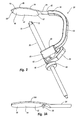
- guide assembly 30 Depicted in Figure 2 is one embodiment of a guide assembly 30 which is now used for forming a tunnel through a portion of tibia 12. As discussed below in greater detail, the tunnel can be used for preparing tibia 12 for a condylar implant and/or securing a condylar implant to tibia 12.
- guide assembly 30 includes a substantially U-shaped guide brace 32 having a template 34 and a tubular guide sleeve 36 mounted on opposing ends thereof. More specifically, guide brace 32 has a first end 38 and an opposing second end 40. Recessed in first end 38 is a socket 42.
- Template 34 comprises a low profile base plate 44 having a top surface 46 and an opposing bottom surface 48 which each extend between a first end 50 and an opposing second end 52.
- bottom surface 48 has a configuration generally complementary to medial facet 24 of the superior auricular surface of tibia 12.
- Base plate 44 typically has a maximum thickness extending between surfaces 46 and 48 in a range between about 1 mm to about 4 mm.
- Protruing from second 52 of base plate 44 is a stem 54.
- Stem 54 is configured to be slidably received within socket 42 of guide brace 32.
- a catch 56 downwardly extends from bottom surface 48 of base plate 44 at first end 50. As depicted, catch 56 has the configuration of a narrow finger. In other embodiments, catch 56 can comprise an elongated ridge or other configurations.
- enlarged housing 60 Formed on second end 40 of guide brace 32 is an enlarged housing 60 having a passage 62 extending therethrough.
- a resiliently flexible clamp arm 64 is mounted to housing 60.
- An aperture 66 extends through clamp arm 64 in general alignment with passage 62.
- Tubular guide sleeve 36 slidably extends through passage 62 and aperture 66.
- Guide sleeve 36 has a proximal end 68 and an opposing distal end 70.
- a plurality of sharpened teeth 72 are formed at distal end 70.
- template 34 is slid over medial facet 24 of tibia 12, i.e., the articulation surface, so that catch 56 catches on posterior side 19 of tibia 12. Catch 56 thus facilitates proper positioning of template 34 and also helps to retain template 34 on medial facet 24.
- the present invention comprises a plurality of alternative templates 34 which are configured for placement on one of the lateral and medial facet and which each have a different configuration. As such a number of the alternative templates 34 can be initially test fitted to determine one that has a best fit for a particular patient.
- template 34A is smaller than template 34.
- template 34A has a catch 56A downwardly extending from second end 52 of base plate 44. Catch 56A thus biases against anterior side 18 or medial side 16 of tibia 12 to help properly position template 34A.
- the projection in contrast to positioning the projection on one of the opposing ends of base plate 44, the projection can be positioned along one of the opposing sides of base plate 44 so as to bias against lateral side 14 (when used on lateral facet 22) or bias against medial side 16 of tibia 12.
- tubular guide sleeve 36 is advanced within housing 60 so that teeth 72 at distal end 70 bias against medial side 16 of proximal end 10 of tibia 12. As such, tubular guide sleeve 36 biases against tibia 12 at a location spaced apart from the articulation surface of medial facet 24. Guide sleeve 36 is then secured in place by releasing clamp arm 64. By securing guide sleeve 36 against tibia 12, guide assembly 30 is clamped onto tibia 12. In one alternative embodiment, guide sleeve 36 can be biased against anterior side 18 of tibia 12.
- a tubular drill sleeve 76 is inserted into tubular guide sleeve 36.
- a guide wire 78 Positioned within drill sleeve 76 is a guide wire 78.
- guide wire 78 is drilled through tibia 12 until guide wire 78 reaches template 34, thereby forming a guide tunnel.
- template 34 functions as a shield to prevent guide wire 78 and/or other drill tools from accidentally contacting and damaging the femur.
- a hole or recess is formed on template 34.
- Guide wire 78 can be passed through or into the hole or recess to ensure complete formation of the tunnel on medial facet 24.
- guide wire 78 and drill sleeve 76 are removed from guide sleeve 60.
- a larger drill tool such as a larger guide wire, drill bit, or the like is then passed through guide sleeve 60 and drilled through tibia 12 along the guide tunnel to form a final tunnel 90 ( Figure 4) through tibia 12.
- any number of progressively larger drill tools can be used.
- guide wire 78 and drill sleeve 76 can be eliminated.
- a single larger drill tool can then be used to form tunnel 90 in a single pass. Using a sequence of larger drill tools, however, helps ensure proper placement of tunnel 90 and facilitates forming the opening of the tunnel adjacent to template 34.
- the angular orientation of tunnel 90 is typically held constant and is based on the configuration of the implant. However, depending on the amount of bone needed to be resected for mounting the condylar implant, it may be necessary to shift the position of tunnel 90 posterior or anterior. Shifting the position of tunnel 90 posterior-anterior is accomplished by selectively moving stem 54 of template 34 further into or further out of socket 42 of guide brace 32. Once template 34 and guide brace 32 are positioned at their relative positions, a set screw 80 is tightened so as to secure template 34 and guide brace 32 together. Predefined markings 82 are formed on stem 54 to help define the relative positioning between template 34 and guide brace 32.
- tunnel 90 has an interior surface 92 that extends from a first end 94 to an opposing end second end 96.
- First end 94 is formed on medial side 16 of proximal end 10 of tibia 12.
- Second end 96 is formed on medial facet 24 of tibia 12.
- second end 96 of tunnel 90 is formed on a section of an articulation surface, i.e ., medial facet 24, while first end 94 is at a location on tibia 12 that is spaced apart from the articulation surface.
- tunnel 90 can be any desired size, in one embodiment tunnel 90 has a diameter in a range between about 5 mm to about 10 mm.
- tunnel 90 is formed by procedures that are minimally invasive to the patient. As discussed below in greater detail, once tunnel 90 is formed, tunnel 90 can then be used to assist in the resection of medial fact 24 and/or the mounting of a condylar implant on the resected medial facet 24. Furthermore, by using tunnel 90 the resection of medial facet 24 and the mounting of the condylar implant can also be performed using procedures that are minimally invasive.
- tunnel 90 is used in the resection of tibia 12 for preparing tibia 12 to receive a condylar implant.
- the resection of tibia 12 can be accomplished using a number of different procedures.
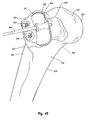
- a rasp assembly 100 is used in association with a retention rod 102 to facilitate resection of tibia 12.
- rasp assembly 100 comprises a rasp body 104 having a pivot arm 105 mounted thereon, a rasp guide 106, and a cover plate 108. More specifically, as depicted in Figures 6 and 7, rasp body 104 has a top surface 110 and an opposing bottom surface 112 that each extend between a proximal end 114 and an opposing distal end 116. Transversely extending across bottom surface 112 are a plurality of ridges 118 that each terminate at a sharpened cutting edge 120. It is appreciated that ridges 118 and cutting edges 120 can be at any desired orientation or combination of different orientation that facilitate cutting.
- Bottom surface 112 is configured such that reciprocating movement of bottom surface 112 on tibia 12 produces a recess on tibia 12 that can receive a desired implant.
- Recessed on top surface 110 of rasp body 104 is a guide slot 122.
- Guide slot 122 is bounded by a floor 124 and a sidewall 126 upstanding from floor 124. Extending through floor 124 to bottom surface 112 is an opening 128.
- Rasp guide 106 comprises a slide plate 130 having a top surface 131 and an opposing bottom surface 133. Downwardly projecting from bottom surface 133 are a pair of spaced apart forks 132A and 132B with a pin 134 extending therebetween. Forks 132A and B have facing interior surfaces 136 which bound a gap 137 and have opposing exterior surfaces 138. Forks 132A and B terminate at a free terminus 140. Exterior surface 138 of each fork 132A and B is recessed at terminus 140 such that a sloping shoulder 142 is formed on each fork 132A and B.
- Rasp guide 106 is received within guide slot 122 so that forks 132A and B project through opening 128. Rasp guide 106 is slightly smaller than guide slot 122 such that forks 132A and B are free to reciprocate within opening 128 as slide plate 130 reciprocates within guide slot 122. As shown in Figure 5, cover plate 108 is secured within guide slot 122 so as to retain rasp guide 106 within guide slot 122. Cover plate 108 can be mounted using conventional techniques such as welding, press fit, and the like. Holes 144 are formed through cover plate 108 to prevent unwanted build-up of resected bone particles within guide slot 122.
- pivot arm 105 has a proximal end 146 and an opposing distal end 148.
- a set hole 149 extends through pivot arm 105 toward proximal end 146.
- Distal end 148 of arm 105 is hingedly mounted to proximal end 114 of rasp body 104 by a pin 150.
- an insertion handle 160 is used to place rasp body 104 over medial facet 24 of tibia 12.
- Insertion handle 160 has a proximal end 162 and an opposing distal end 164.
- a post 165 is formed a proximal end 162.
- Post 165 is adapted to receive an extension handle if desired.
- a pair of spaced apart lips 166A and B project from distal end 164 and bound a slot 163.
- a channel 168 ( Figure 5) longitudinally extends through insertion handle 160 so as to communicate with slot 163.
- Channel 168 is configured to receive pivot arm 105 when rasp body 104 is received within slot 163.
- pivot arm 105 is slid into channel 165 from between lips 166A and B. Lips 166A and B are then advanced to extend above and below proximal end 114 of rasp body 104.
- a set screw 168 ( Figure 7) is then advanced into insertion handle 160 so as to extend through set hole 149 on pivot arm 105. In this configuration insertion handle 160 rigidly supports rasp body 104 so as to prevent hinged movement of rasp body 104 during insertion.
- retention rod 102 comprises a tubular set rod 172 bounding a channel 174 extending from a proximal end 176 to an opposing distal end 178. Distal end 178 terminates at a distal end face 179. A handle 180 outwardly projects from proximal end 176 to facilitating grasping retention rod 102.
- Retention rod 102 further comprises a hook rod 182.
- Hook rod 182 has a proximal end 184 and an opposing distal end 186. Projecting from distal end 186 is a hook 188. Threads 190 are formed on proximal end 184.
- a knob 192 is also provided having a threaded port 193. Threads 190 on hook rod 182 are configured to mate with threaded port 193 of knob 192.
- Hook rod 182 is received within channel 174 of set rod 172 such that knob 192 biases against handle 180 and hook 188 extends beyond distal end face 179. In this configuration, rotation of knob 192 relative to hook rod 182 causes hook 188 to extend or retract relative to set rod 172.
- rasp assembly 100 is mounted on medial facet 24 of tibia 12. Rasp assembly 100 is positioned using the rigidly mounted insertion handle 160, as discussed above, such that forks 132A and B ( Figure 7) are aligned with the second end 96 of tunnel 90. Once rasp assembly 100 is positioned, retention rod 102 is advance within tunnel 90 from first end 94. As depicted in Figure 9A, knob 192 is rotated so that hook 188 extends beyond set rod 172. With hook 188 freely exposed, hook 188 is hooked over pin 134 extending between forks 132A and B.
- knob 192 is rotated so as to advance set rod 172 toward hook 188.
- Set rod 172 is advanced until distal end face 179 of set rod 172 biases against shoulders 142 of forks 132A and B. Shoulders 142 are sloped such that end face 179 can sit flush against shoulder 142 while set rod 172 retains its orientation within tunnel 90. In this configuration, retention rod 102 is securely fixed to rasp guide 106.
- rasp body 104 reciprocates along a length in a range between about 1 mm to about 4 mm. Other dimensions can also be used.
- bottom surface 112 of rasp body 104 slightly arched so as to be convex.
- pivot arm 105 hingedly attached to rasp body 104 rasp body 104 is free to reciprocate along the arched path.
- the hinged attachment also helps to minimize binding of rasp body 104.
- arm 105 can be rigidly attached to rasp body 104.
- means are provided for removably engaging retention rod 102 with rasp body 104 such that rasp body 104 can be selectively reciprocated without substantial movement of retention rod 102.
- one embodiment of the means comprises rasp guide 106 slidably mounted on rasp body 104 and hook 188 mounted on retention rod 102.
- pin 134 and hook 188 can be replaced with a threaded connection, bayonet connection, or any number of other conventional connections which allows retention rod 102 to engage with rasp guide 106.
- rasp guide 106 can be mounted on rasp body 104 in a variety of different ways.
- opening 128 can extend through rasp body 104 without the formation of guide slot 122.
- slide plate 130 can be positioned directly on top surface 110 of rasp body 104 while forks 132A and B extend through opening 128.
- guide slot 122 can be formed on bottom surface 112 of rasp body 104.
- Cover plate 108 can be formed having opening 128 extending therethrough and cutting edges 120 formed on a bottom surface thereof. Slide plate 130 can be positioned within the guide slot 122 so that when cover plate 108 is secured over guide slot 122, forks 132A and B extend through opening 128 formed on cover plate 108.
- retention rod 102 can have a variety of different configurations.
- set rod 172 can be eliminated.
- retention rod 102 can simply comprise hook rod 182.
- hook 188 can be replaced with a variety of different types of connectors.
- rasp assembly 100 and retention rod 102 are removed.
- the resected bone particles are removed by conventional flushing and suction.
- tibia 12 now has a resected recess 194 formed on medial facet 24.
- the resection of tibia 12 can be accomplished using a variety of different techniques.
- the resection of tibia 12 is accomplished by cutting through an area bounded by a cutting template 200.
- Cutting template 200 comprises a plate 202 having a top surface 204 and an opposing bottom surface 206.
- cutting template 200 is configured to rest on lateral facet 22 of tibia 12.
- cutting template 200 can also be designed for resting on medial facet 24.
- Guide spaces 208 are formed so that when cutting template 200 is positioned, guide spaces 208 are positioned over at least a portion of the facet to be resected.
- guide spaces 208 have the configuration of an elongated channel.
- the channels facilitate guided receipt of a cutting burr 210 which is used to selectively remove the unwanted bone.
- guide spaces 208 can come in a variety of different sizes, shapes, and orientations.
- a second cutting template is provided having guide spaces extending therethrough.
- the guide spaces are aligned so as to bound the area of the facet to be resected which was blocked by plate 202 of cutting template 200.
- Cutting template 200 is used in association with retention rod 102 as previously discussed.
- handle 180 has a different configuration.
- cutting template 200 is position over lateral facet 22.
- Distal end 178 of set rod 172 is advanced through tunnel 90 so that hook 188 of hook rod 182 projects out of set rod 172.
- Hook 188 is passed though a guide space 208 and then pulled back onto top surface 204 of plate 202.
- a rib 212 upwardly projects from plate 202 adjacent to guide space 208. Hook 188 is hooked over rib 212 so as to improve the engagement between hook 188 and cutting template 200.
- knob 192 is rotated so as to bias set rod 172 against bottom surface 206 of template 200.
- retention rod 102 is securely clamped to cutting template 200.
- cutting template 200 is securely held in place on lateral facet 22.
- Cutting burr 210 or some other form of drill bit is then advanced into and along each of guide spaces 208 so as to resect the portion of the bone directly below guide space 208.
- cutting template 200 can be removed and replaced with a second template. Burr 100 can then be passed through guide spaces of the second template to remove further bone that was covered by cutting template 200.
- a single template can be rotated or shifted on lateral facet 22 so that the single template is used to remove the desired bone.
- means are provided for removably engaging retention rod 102 to cutting template 200 so that retention rod 102 secures cutting template 200 to the lateral or medial facet of tibia 12 when retention rod 102 is received within tunnel 90 of tibia 12.
- one embodiment of such means comprises hook 188 and guide space 208 which enables hook 188 to engage with cutting template 200.
- the present invention also envisions that there are a variety of other structures that can accomplish the same function.
- the same structures and techniques as discussed above for securing retention rod 102 to rasp assembly 100 can also be used with cutting template 200. That is, in one alternative forks 132A and B with pin 134 can be mounted on bottom surface 206 of plate 202. Other connections such as threaded connection, bayonet connections, and the like can also be used.
- FIG. 12 depicted in Figure 12 is a guide 214.
- Guide 214 comprises rod 216 having an upper end 217 and an opposing lower end 218.
- Adjustably mounted on lower end 218 of rod 216 is a brace 219 having a v-shaped notch 220.
- Notch 220 is configured so that brace 219 can be securely held against the distal end of tibia 12.
- Adjustably mounted at the upper end of rod 216 is an adjustment mechanism 222.
- Adjustment mechanism 222 comprises an elongated body 223 having rod 216 slidably extending therethrough.
- a handle 224 and an adjacent trigger 225 are each connected to body 223.
- Trigger 225 is connected to a cam 226 which is spring biased against rod 216. As such, by retracting trigger 225, cam 226 is pulled back and adjustment mechanism 222 can freely slide along rod 216. Once trigger 225 is released, cam 226 is spring biased against rod 216, thereby securing adjustment mechanism 222 in place.
- a cutting guide 228 is connected to body 223 by a post 229. Alternatively, cutting guide 228 can be directly connected to body 223.
- Cutting guide 228 has an inside face 230 and an opposing outside face 231.
- An elongated slot 232 extends between faces 230 and 231.
- Inside face 230 is contoured so as to closely fit against the anterior side of medial condyle 21.
- guide 214 is positioned against tibia 12 as shown in Figure 12.
- An operator uses handle 224 to biases guide 214 against tibia 12 so that guide 214 is securely held in position.
- a blade on an oscillating saw (not shown) is advanced through slot 232 in cutting guide 228.
- slot 232 as a guide, the blade on the oscillating saw is advanced anterior to posterior through the medial condyle 21 so as to form resected surface 234.
- the saw blade also cuts through the medial side of medial condyle 21.
- Cutting guide 228 is positioned so that the saw blade removes the articular cartilage of medial condyle 21.
- cutting guide 228 is positioned so that slot 232 is positioned at a distance typically in a range between 1 mm to about 4 mm below medial facet 24. Other dimensions can also be used.
- resected surface 234 can be formed through the use of an electric burr, mill, bone chisel, bone chipper or the like.
- the above resection process can be used in combination with the rasping process previously discussed. That is, either before or after forming tunnel 90, the oscillating saw or other tool can initially be used to remove the articular cartilage before rasping.
- the option has the benefit of easy removal of the articular cartilage which can be difficult to remove by rasping. Furthermore, the total amount of material to be removed by rasping is reduced.
- the above resection process provides a planar surface on the tibia which is more convenient to work with when forming a pocket for the implant.
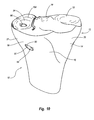
- resected surface 234 is a further resected to form a contoured pocket in which the implant can be mounted.
- Guide template 236 comprises a body 237 having a top surface 238 and an opposing bottom surface 239.
- surfaces 238 and 239 are each substantially flat and form a thickness extending therebetween which is typically in a range between about 0.5 mm to about 4 mm.
- Body 237 has an interior surface 240 which encircles an opening 241 extending between surfaces 238 and 239.
- Opening 241 has an area that corresponds to the size of the implant.
- opening 241 can be any size or shape depending on the size and shape of implant to be used.
- opening 241 has an elongated configuration and typically has an area greater than about 2 cm 2 and more commonly greater than 3 cm 2 . Again, other sizes and shapes can be used.
- body 237 need not completely encircle opening 241. For example, a section of body 237 bounding opening 241 can be eliminated.
- Body 237 has an anterior side 248 and an opposing posterior side 249. Projecting from anterior side 248 is an elongated handle 242. Extending along bottom surface 239 of body 237 and handle 242 is a recessed channel 244. Rotatably disposed within channel 244 is a shaft 245. Shaft 245 has a first end 246 disposed at the free end of handle 244 and an opposing second end 247 disposed at posterior side 249 of body 237. A handle 250 is connected to first end 247 of shaft 245. Handle 250 enables the user to easily rotate shaft 245 by selective movement of handle 250. Outwardly projecting from second send 247 of shaft 245 is a catch 252.
- catch 252 can be selective moved between a first position wherein catch 252 is disposed in the same plane as body 237 and a second position, as shown in Figure 14, wherein catch 252 orthogonally projects below bottom surface 239 of body 237.
- catch 252 is initially oriented in the first position.
- Body 237 can then be easily slid anterior to posterior along resected surface 234.
- Catch 252 can then be rotated to the second position such that catch 252 catches on the posterior side of tibia 12.
- Catch 252 can thus be used to facilitate proper placement and stabilization of guide template 236 on resected surface 234.
- guide template 236 is positioned, it is checked for proper fit. That is, body 237 should extend complimentarily around the perimeter edge of resected surface 234. If not, guide template 236 is replaced with a guide template of different size and/or shape.
- a plurality of guide templates 236 are provided having different sizes to fit patients of different size. It is also appreciated that guide template 236 can be configured to be adjustable in size and/or shape.
- means are provided for securing body 237 to tibia 12.
- a first hole 254 and a second hole 256 are formed at two-spaced apart locations along or adjacent to anterior side 248 of body 237.
- the holes can also be formed on handle 242.
- a tubular sleeve 258 encircles and upwardly projects at an angle from each of holes 254 and 256.
- sleeves 258 function as a guide but are not required.
- a pair of screws 260 are provided each having an enlarged head 261.
- screws 260 are advanced through corresponding holes 254 and 256 so as to screw into the anterior side of tibia 12.
- guide template 236 is secured in place so as to prevent unwanted sliding or rotation.
- a single hole and screw can be used or three or more holes and corresponding screws can be used.
- other types of fasteners such as barbs, spikes, expansion bolts, staples, clamps, or the like can be used to secure body 237 to tibia 12.
- rasp 264 is positioned on guide template 236.
- rasp 264 comprises a head 266 having an elongated handle 267 projecting therefrom.
- Head 266 includes an inside face 268 and an opposing outside face 269.
- Projecting from inside face 268 is a cutting mount 270.
- Counting mount 270 comprises a base 272 projecting from inside face 268 and a plurality of cutting teeth formed on base 272.
- Cutting mount 270 has a configuration smaller than opening 241 on guide template 236 such that cutting mount 270 can be received within opening 241 as shown in Figure 15 and can be reciprocated back and forth therein.
- cutting mount 270 reciprocally slides back and forth within opening 241 along a distance in a range between about 3 mm to 15 mm. Other dimensions can also be used. Cutting mount 270 also has a thickness which is greater than the thickness of body 237 of guide template 236. As a result, cutting teeth 237 ride against resected surface 234 when cutting mount 270 is received within opening 241. During the reciprocating movement, guide template 236 functions as a guide for rasp 264 so that only the bone bounded within opening 241 can be removed.
- cutting mount 270 is smaller than head 266 such that an openly exposed portion of inside face 268 encircles cutting mount 270.
- Head 266 has an outer perimeter generally corresponding to the outer perimeter of body 237 of guide plate 236 such that head 266 extends over body 237 when cutting mount 270 is received within opening 241.
- cutting mount 270 is reciprocated within opening 241
- cutting teeth 273 cut away at the bone bounded within opening 241.
- the bone is continually cut away until head 266 biases against body 237, thereby precluding further advancement of cutting mount 270 into opening 241.
- a plurality of open channels 274 extend through cutting mount 270 and head 266.
- rasp 264 can come in a variety of alternative configurations.
- cutting teeth 273 could be elongated so as to extend directly from head 266.
- head 266 can have the same perimeter dimensions as cutting mount 270.
- handle 267 would still overlay guide template 236.
- the size and arrangement of channels 274 and cutting teeth 273 can be modified in a variety of different configurations.
- cutting mount 270 has a rounded bottom surface that outwardly curves front to back and side to side. As a result, as depicted in Figure 17, once rasp 264 is removed, a rounded pocket 278 is formed on resected surface 234. It is appreciated that cutting mount 270 can have a variety of different configurations so as to form pocket 278 of a corresponding shape. As will be discussed below in greater detail, pocket 278 is configured to provide a best fit for mounting the implant. In alternative embodiments where the bottom of the implant is substantially flat, rasp 264 need not be required in that resected surface 234 can be positioned at the desired level to receive the implant. Alternatively, rasp 264 can be formed so that cutting mount 270 has a substantially flat face. In yet other embodiments, cutting mount 270 can be configured to form grooves, channels, slots or the like to fit corresponding projections extending from the implant.
- a tunnel 400 is formed intersecting with pocket 278 so that the implant can be mounted.
- Guide assembly 30, as previously discussed with regard to Figures 2 and 3, can be used to form tunnel 400 either before or after the formation of pocket 278 in the same way that tunnel 90 was formed.
- a centering template 280 is mounted on guide template 236.
- centering template 280 comprises a mounting plate 282 having an elongated handle 283 projecting therefrom.
- Mounting plate 282 comprises an upper plate 284 having an inside face 285. Projecting from inside face 285 is a boss 286.
- Boss 286 has a configuration complimentary to opening 241 of guide template 236.
- boss 286 is slightly smaller than inside face 285 of upper plate 284.
- upper plate 284 extends over a portion of guide plate 236. This coupling provides a fixed positioning of centering template 280 relative to guide template 236.
- contact boss 288 Projecting from boss 286 is a contact boss 288.
- Contact boss is positioned so as to be located over the intended opening for tunnel 400. This location is typically at the center of resected surface 234. Other locations, however, can also be used. As will be discussed below in greater detail, contact boss 288 acts in part as a stop for the drill forming tunnel 400 within tibia 12 so that the drill does not damage the femur.
- centering indent 290 is used in association with a tunnel guide for positioning the placement of tunnel 400.
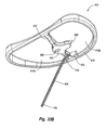
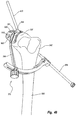
- Tunnel guide 370 comprises a brace 372 having an inside face 382 and an opposing outside face 383 that each extend between a first end 373 and an opposing second end 374. Second end 374 has a channel 376 extending therethrough. Sideably disposed within channel 376 is a tubular guide sleeve 378.
- a clamp arm 380 is coupled with brace 372 and resiliently biases against guide sleeve 378. As such, by depressing clamp arm 380, guide sleeve 378 can be selectively slide to a desired location and then secured in position by release of clamp arm 380.
- An elongated slot 384 extends along the length of brace 372 at first end 373 and extends between inside face 381 and outside face 382.
- Tunnel guide 370 further comprises an elongated alignment arm 386 having a first end 388 slidably disposed within slot 384 and an opposing second end 390. Second end 390 terminates at a rounded tip 391.
- An adjustment knob 392 threadedly engages first end 388 of alignment arm to brace 372. Rotation of adjustment knob 392 in a first direction allows second end of alignment arm 386 to freely slide along slot 384. By rotating adjustment knob 392 in the opposing direction, alignment arm 386 is rigidly clamped to brace 372.
- guide sleeve 378 has a central longitudinal axis 394 extending therethrough. Tunnel guide 370 is configured such that independent of the placement of alignment arm 386 along slot 384, axis 394 is always aligned with tip 391.
- guide sleeve 378 is shown being biased against lateral side 14 of tibia 12. In alternative embodiments, it is also appreciated that guide sleeve 378 can be biased against anterior side 18 or medial side 16 of tibia 12.
- a guide wire 396 is passed through guide sleeve 378 and then drilled through tibia 12 until guide wire 396 contacts boss 288 ( Figure 19).
- a tunnel 400 is formed having a first end 402 located at a position spaced apart from resected surface 234 and a second end 404 ( Figure 17) which extends through pocket 278 on resected surface 234.
- tunnel 400 receives a flexible line that is mounted to the implant.
- passing the flexible line through tunnel 400 requires tunnel 400 to have a diameter typically in a range between 1 mm to about 3 mm. Of course, larger diameters can also be used.
- guide wire 396 can be used to independently form tunnel 400.
- a tubular drill sleeve can be positioned over guide wire 396 to enlarge tunnel 400.
- guide wire 396 can be removed and a larger drill can be passed through the preliminary tunnel formed by the guide wire 396 to form the final tunnel 400.
- first end 402 of tunnel 400 is secured within first end 402 of tunnel 400.
- the bone anchor requires a larger opening than what is necessarily needed for the line to pass through tunnel 400. Accordingly, where the tunnel 400 is minimized to limit bone removal, first end 402 of tunnel 400 is counter bored with a larger drill so as to enable proper placement of the bone anchor.
- tunnel 400 can be counter sunk so as to have a diameter in a range between about 4 mm to 8 mm. Again, other dimensions can also be used.
- tunnel guide 370 Once tunnel 400 is formed, tunnel guide 370, centering template 280, and guide template 236 are removed from tibia 12. Accordingly, by using any of the aforementioned methods and/or combinations thereof, a resected medial condyle having a tunnel coupled therewith, is now ready to receive an implant.
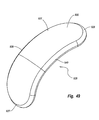
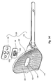
- condylar implant 300 incorporating features of the present invention.
- the term "condylar implant” is broadly intended to include implants that can replace all or a portion of a condyle of a tibia.
- the condylar implant can also replace all or a portion of the articulation surface of the condyle. Accordingly, while the depicted embodiments show one conventional size and configuration for a condylar implant, in alternative embodiments the condylar implant can be larger to replace more of the tibia or can be smaller to replace only a section of a condyle of a tibia. In such alternatives, the condylar implant can have a variety of different configurations.
- condylar implant 300 has a top articular surface 306 and an opposing bone apposition surface 303.
- top articular surface 306 has a generally concave contour that curves front to back and side to side so as to mate with a corresponding femoral condyle.
- articular surface 306 can be substantially flat.
- Bone apposition surface 303 has a generally convex contour that curves front to back and side to side and that is configured to mate with pocket 278 on resected surface 234 ( Figure 17).
- implant 300 can be formed having a low profile configuration with a generally uniform thickness along the length thereof. This uniform thickness provides uniform strength for implant 300.
- contouring implant 300 to fit within pocket 278, the stability of mounted implant 300 is increased so as to prevent unwanted movement of implant relative to tibia 12.
- bone apposition surface 303 can be substantially flat.
- implant 300 can be mounted directly on flat resected surface 234.
- contouring of articular surface 306 would result in the opposing ends of implant 300 being thicker than the middle.
- implant 300 can have an array of different sizes and configurations.
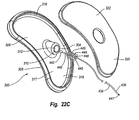
- implant 300 comprises a body 301 and an inlay 320.
- Body 301 has top articular surface 306 and an opposing bottom surface 308.
- a pocket 316 is recess on bottom surface 308.
- Pocket 316 is bounded by a floor 317 and a sidewall 318 upstanding around the perimeter thereof.
- a stem 304 projects from floor 317 and is completely encircled by pocket 316.
- Body 301 is typically comprised of a metal such as chromium, cobalt, titanium, or the like and alloys thereof but can also be made of ceramics, plastics, or other materials.
- Body 301 can also be comprised of layers or sections of different materials.
- body 301 has a maximum thickness typically in a range between about 2 mm to about 10 mm. Other dimensions can also be used depending on the amount that the tibial condyle is resected or worn away.
- Inlay 320 is secured within pocket 316 of body 301 so as to encircle stem 304.
- Inlay 320 is comprised of a porous bone ingrowth material such as porous tantalum. Other conventional porous bone ingrowth materials can also be used.
- Inlay 320 is secured within pocket 316 using conventional techniques such as press fit, welding, adhesive, sintering, and the like.
- Inlay 320 can also be mechanically connected to body 301 such as by screws, fasteners, rivets, or the like.
- pocket 316 can be eliminated and inlay 320 can be secured to the bottom surface of body 301 using various techniques.
- Inlay 320 has an exposed bottom surface 322 that, as discussed above, can be arched, substantially flat, or can have any other desired configuration.
- bottom surface 322 of inlay 320 comprises substantially all of bone apposition surface 303 of base plate 301.
- body 301 can be formed having a plurality of pockets each adapted to receive a separate inlay.
- an implant 410 comprising a body 412 having a bottom surface 414.
- Bottom surface 414 is formed with two pockets 416A and B which are partially bounded by a perimeter sidewall 418 and are separated by a central bridge 420.
- Each pocket 416A and B is adapted to receive a corresponding inlay 422A and B.
- the bone apposition surface includes not only the bottom surface of inlays 422A and B but also the bottom surface of bridge 420 and perimeter sidewall 418.
- Body 424 for an implant.
- Body has a bottom surface 424 with three separate pockets 426A, B, and C.
- Each of the pockets 426 is adapted to receive a separate inlay.
- the bridges formed between the separate pockets provide increased structural support for the implant and, as will be discussed below in greater detail, provide a structure on which the flexible line can be attached.
- the condylar implant can comprise a single integral member.
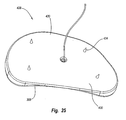
- FIG. 25 depicted in Figure 25 is an alternative embodiment of a condylar implant 428.
- Implant 428 is formed as a single integral body 430 having top articular surface 306 and an opposing bottom surface 430 which also functions as the bone apposition surface.
- a plurality of spikes 434 are formed on bottom surface 430. It is appreciated that in all of the embodiments herein that spikes, fins, or other forms of projections can also be formed projecting from bottom surface of the implant.
- Such projections can be separated from or encircled by the porous bone ingrowth inlay.
- the projections can also be formed on the porous bone ingrowth inlay.
- Such projections can penetrate into the tibia or be received within slots formed on the tibia to help prevent unwanted movement of the implant.
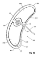
- the term "line” is broadly intended to include wire, cable, cord, suture, braded line, combinations thereof or any other type of flexible filament.
- the line can be made of metal, alloys, synthetics, composites, or any other desired material.
- the line comprises braded filaments of a cobalt chrome alloy having a diameter in a range between about 0.25 mm to about 5 mm with about 0.5 mm to about 3 mm being more common and about 0.5 mm to about 2 mm being most common. Other dimensions can also be used.
- the line can be of any desired length.
- the line can also be defined in that for an unsupported length of line of 4 cm, the line has substantially no compressive strength. In yet other embodiments, for an unsupported length of line of 4 cm, the line fails under buckling when an axial compressive load of 0.25 N, 1 N, 2 N, 5 N, 20 N, or 50 N is applied. That is, different lines can be used that fail under different loads. Stiffer lines can also be used.
- the line can be static or resiliently stretchable.
- the line can be comprised of a material have shape memory of pseudo elastic properties.
- a material has shape memory of pseudo elastic properties.
- Nitinol sold under the name Nitinol.
- sections of the line could be replaced with a spring member such as a coiled spring or rubber or bungee type member.
- an elongated line 438 having a first end 439 and an opposing second end 440.
- First end 439 terminates at a tip 441 that is sealed so as to have and maintain a smooth uniformed diameter.
- Second end 440 terminates at an enlarged rounded head 442.
- second end 440 can have the same configuration as first end 439 or can have an enlarged head of any desired configuration.
- means are provided for connecting flexible line 438 to implant 300.
- stem 304 is provided with a threaded socket 312.
- Slidably disposed on line 438 is a tubular retainer 444.
- Retainer 444 comprises a body 445 having one or more helical threads 446 mounted on the exterior surface thereof. Threads 446 are configured to engage with threaded socket 312.
- a channel 448 longitudinally extends through body 445. Channel 448 constricts toward the distal end of body 445 so that the channel 448 thereat is larger than the diameter of line 438 but smaller than the diameter of head 442.
- the proximal end of channel 448 is enlarged and has a polygonal transverse cross section.
- first end 439 of line 438 can be passed through channel 448 of body 445 distal to proximal.
- Line 438 can then be pulled through retainer 444 until head 442 is stopped by the constricted section of channel 448.
- the first end of line 438 can then be advanced through a central channel in a tubular driver (not shown) having a free end adapted to fit within channel 448 of retainer 444 at the proximal end thereof.
- the driver can thus be used to screw retainer 444 into threaded socket 312, thereby securing line 438 to implant 300.
- FIG. 23B Depicted in Figure 23B is another embodiment of the means for connecting a line to an implant.
- a passage 464 extends through bridge 420.
- Passage 464 has an entrance 465 formed on a side wall of bridge 420 and an exit 466 formed on a bottom surface of bridge 420. Again, passage 464 constricts as it extends from entrance 465 to exit 466.
- Line 438 is shown having an enlarged substantially cylindrical head 442 formed on second end 440. Head 442 is larger than the constricted portion of passage 464. Head 442 can be crimped, welded, or otherwise formed on line 438. Head 442 can also be integrally formed with line 438. During assembly, first end 439 of line 438 is passed through passage 464 from entrance 465 to exit 466.
- Line 438 is advanced through passage 464 until head 442 is captured and securely retained within constricted passage 464.
- Inlays 422A and B can then be positioned within pockets 416A and B.
- head 442 can be wedge shaped so that head 442 is captured within passage 464.
- FIGS 26-31 Depicted in Figures 26-31 are a variety of still other embodiments of the means for connecting a line to an implant.
- a stem 450 mounted to implant 300 which can be selectively crimped so as to catch head 442 within stem 450. In one embodiment this can be accomplished by forming slots along stem 450.
- a hook 452 is formed projecting from the bottom surface of body 301 of implant 300.
- a loop 454 is formed at the second end of line 438. Loop 454 is looped around hook 452.
- Inlay 320 is then mounted on the bottom surface of body 301 so as to prevent loop 454 from accidentally sliding off of hook 452.
- a channel 456 can be formed extending through implant 300 from top surface 306 to bottom surface 308.
- Channel 456 is enlarged at top surface 306 so as to receive head 442 of line 438 but constricts toward bottom surface 308 so as to capture head 442 within channel 456.
- the opening to channel 456 on top surface 306 can be rounded to prevent unwanted wear on the femoral condyle.
- a plug can be inserted within channel 456 so as to occlude the opening to channel 456.
- a constricted slot can be formed that inwardly extends from the side of implant 300.
- a set screw 458 is screwed into the side of a tubular stem 459 to capture head 456 therein.
- a tubular retainer 460 can be provided with outwardly projecting barbs 461. Retainer 460 can simply be pushed into a socket 462 having threads or barbs thereon so that retainer 460 is captured therein.
- line 438 is shown comprising a resiliently stretchable spring 468. It is appreciated the spring 468 can be directly connected to the implant or disposed along line 438. Spring 468 can also come a variety of different shapes and sizes and be made from different materials. As will be discussed below in greater detail, spring 468 helps maintain the desired tension force on line 438 so that the implant is securely held in position.
- an implant 470 has a body 471 with a bottom surface 472.
- a pair of spaced apart projections 474A and B project from bottom surface 472.
- a passage 475 extends through each projection 474A and B.
- Line 438 is passed through each passage 475 so that line 438 is slidably connected to implant 470 with both ends 439 and 440 of line 438 being freely disposed.
- both ends 439 and 440 of line 438 are separately connected to the bone. Since line 438 is slidably connected to implant 470, this embodiment functions like a pulley in that a tensioning force applied to one end of line 438 is magnified as is passes through the passages 474. As such, greater force can be used to secure the implant without increasing the load on line 438.
- line 438 can be connected to only a single projection 474. It is also appreciated that a first line can be connected to projection 474A while a second line is connected to projection 474B. In like manner, it is appreciated that in all embodiment disclosed herein, two or more discrete lines can be connected two each of the implants using any of the methods disclosed herein. It is also appreciated that there are still a large number of other ways in which line 438 can be secured to an implant. For example, the line can be welded, press fit, or attached by a variety of different types of fasteners such as bolts, rivets, or clamps.
- condylar implant 326 Depicted in Figures 32A and B is another alternative embodiment of a condylar implant 326. Like elements between condylar implants 300 and 326 are identified by like reference characters. In contrast to condylar implant 300 which is fixed and rigid, condylar implant 326 is mobile. Specifically, in condylar implant 326 the body comprises a lower bearing plate 328 from which the flexible line projects and an upper bearing plate 330 that is slidably mounted on lower bearing plate 328.
- Lower bearing plate 328 has a top surface 332 and an opposing bottom surface 334 with a perimeter edge 335 extending therebetween. Pocket 316 is formed on bottom surface 334 to receive inlay 320.
- stem 304 is shown elongated and at an angle. If desired, stem 304 can be formed long enough so that it extends directly into the tunnel formed on the tibia. Likewise, stem 304 can be oriented at any angle to correspond with the tunnel.
- Top surface 332 is substantially flat or inwardly arched and extends between an anterior end 336 and a posterior end 338.
- a track 340 is recessed on top surface 332. Track 340 has an open mouth extending through perimeter edge 335 at anterior end 336 and longitudinally extends toward posterior end 338.
- Track 340 is bounded by a substantially flat floor 343 having a sidewall 344 upstanding therefrom.
- Sidewall 344 comprises a recess groove 345 which extends along floor 343 and an outwardly projecting lip 346 which projects along top surface 332.
- the opposing sidewalls 344 of track 340 form a mortis.
- Upper bearing plate 330 comprises top articular surface 306 and a bottom surface 348 which each extend between an anterior end 350 and an opposing posterior end 352.
- Bottom surface 348 has a configuration substantially congruent to top surface 332 of lower bearing plate 328.
- Projecting from bottom surface 348 is an elongated key 354 which extends from toward anterior end 350 to toward posterior end 352.
- Key 354 has a sidewall 356 that is substantially complementary to sidewall 344 of tack 340 such that key 354 forms a tenon that can slide into track 340 from mouth 342. In this position key 354 can freely slide along track 340 but is prevented from vertically separating from track 340.
- upper bearing plate 330 can slide posterior-anterior on lower bearing plate 328 as the femoral condyle rotates on top articular surface 306. This ability of upper bearing plate 330 to slide minimizes high stress points between the femoral condyle and upper bearing plate, thereby minimizing wear. Furthermore, because bearing plates 328 and 330 slide against each other on congruent surfaces, both of bearing plates 328 and 330 can be comprised of metal without producing undue wear. In other embodiments, bearing plates 328 and 330 can be comprised of plastics, ceramics, or composites of different materials. In addition, bearing plates 328 and 330 can be made of the same or different materials.
- FIG. 33A and B is another alternative embodiment of a condylar implant 360 which includes an upper bearing plate 361 and a lower bearing plate 362.
- lower bearing plate 362 includes a track 363 that is curved along the length thereof.
- Upper bearing plate 361 includes an elongated key 364 having a curve complementary to track 363 such that key 364 can freely slide within track 363.
- key 364 and track 363 can also be arched or curved in a vertical plane.
- Anchor assembly 810 used to secure condylar implant 300 to tibia 12.
- Anchor assembly 810 and line 438 comprise one embodiment of means for securely fixing implant 300 to a natural or resected articulation surface of a bone.
- the alternative embodiments of anchor assembly 810 and line 438 as discussed herein are also consumed within this means.
- more conventional fasteners can also be used to secure the novel implants of the present invention.
- Anchor assembly 810 comprises a bone anchor 812 that operably connects with a lock 813. As discussed below in greater detail, bone anchor 812 is selectively placed by a first drive 814 while lock 813 is selectively placed by a second driver 816.
- bone anchor 812 comprises a tubular body 818 having a substantially cylindrical configuration.
- Body 818 includes an interior surface 820 and an exterior surface 821 that each extend between a proximal end 822 and an opposing distal end 823.
- Distal end 823 tapers to a reduced nose 824.
- Formed at proximal end 822 is an engaging head 827 having an exterior surface with a transverse cross section that is polygonal or any other non-round configuration.
- first driver 814 can connect with engaging head 827 to selectively rotate bone anchor 812.
- Encircling and radially outwardly projecting from exterior surface 821 are one or more helical threads 825.
- Threads 825 can be conventional or self-taping and extend radially outward beyond the outer perimeter of engaging head 827. In alternative embodiments, threads 825 can be replaced by ridges, barbs, or other bone engaging structures used in conventional bone anchors. Bone anchor 825 can be formed of a biocompatible metal, a bioabsorbable polymer, a bioactive ceramic, or any other desired material.
- interior surface 820 bounds a channel 826 longitudinally extending through bone anchor 812. Extending proximal to distal, interior surface 820 comprises a threaded portion 828, a frustoconical tapered portion 830, and a constricted cylindrical portion 833.
- lock 813 comprises a collet.
- lock 813 has a proximal end 836, an opposing distal end 838, and a channel 840 extending therebetween.
- lock 813 comprises a tubular body 846 extending from proximal end 836 to a second end 850. Encircling and radially, outwardly projecting from body 846 are one or more helical threads 854. Threads 854 are configured to engage with threaded portion 828 of bone anchor 812.
- At least a portion of channel 840 extending through body 846 is bounded by an interior surface 847 having a polygonal or other non-circular transverse cross section so that second driver 816 ( Figure 34) can be secured therein for selective rotation of lock 813.
- each finger 856 Projecting from second end 850 of body 846 are a plurality of flexible fingers 856. As depicted in Figure 37, four finger 856 are provided with each finger 856 being separated by a slot 857 extending along the length of fingers 856. In alternative embodiments, two or more fingers 856 can be used. The distal end of each finger 856 is radially, inwardly tapered.
- lock 813 is partially screwed into proximal end 822 of bone anchor 812. In this position, with fingers 856 unflexed, line 438 is passed through channels 826 and 840. As discussed below in greater detail, when it is desired to secure line 438 relative to bone anchor, lock 813 is advanced further into bone anchor 812 until tightly secured therein. In so doing, fingers 856 of lock 813 bias against tapered portion 830 of bone anchor 812 which causes fingers 856 to radially, inwardly constrict and securely engage line 438. In this position, line 438 is prevented from being pulled in either direction. However, line 438 can again be freely moved by simply unscrewing lock 813 from within bone anchor 812 so that fingers 856 are able to freely, outwardly flex.
- first driver 814 comprises a tubular shaft 862 having a proximal end 863 and an opposing distal end 864.
- a handle 865 is formed at proximal end 863.
- a passage 866 extends through shaft 862 and handle 865 so that line 438 can pass completely through first driver 814.
- Passage 866 at distal end 864 has an interior surface that is complementary to the exterior surface of engaging head 827 of bone anchor 812. As such, first driver 814 can be selectively coupled with bone anchor 812 for selective rotation of bone anchor 812.
- Second driver 816 also comprises a tubular shaft 867 having a proximal end 868 and an opposing distal end 870.
- a tubular handle 872 is mounted proximal end 868.
- a passage 874 extends the length of second driver 816 so that line 438 can extend completely therethrough.
- Distal end 870 of shaft 867 terminates at a tip 875.
- Tip 875 has a configuration complementary to channel 840 at proximal end 836 of lock 813.
- second driver 816 can be selectively coupled with lock 813 for selective rotation of lock 813.
- first end 439 of line 438 is passed through tunnel 400 from second end 404 ( Figure 17) to first end 402. In one embodiment this is accomplished by passing an instrument up through tunnel 400 from first end 402 to second end 404. The instrument is then used to grab first end 439 of line 438 and pull it down through tunnel 400. Other techniques can also be used.
- Line 438 is continually pulled through tunnel 400 to remove all slack. With the slack removed, condylar implant 300 is slid onto resected surface 234 so as to fit within pocket 278.
- condylar implant 300 has a relatively low profile, condylar implant 300 can be easily passed through the relatively small incision that was originally formed over the medial meniscus. This is in contrast to other conventional procedures where larger incisions must be made to either allow placement of an implant having a large stem that is embedded within the bone for securing or to provide access room to enable securing the implant by passing screws down through the top of at least a portion of the implant.
- first end 439 of line 438 is passed distal to proximal through channels 826 and 840 of bone anchor 812 and lock 813.
- First end 439 of line 438 then is passed distal to proximal through passage 866 of first driver 814 so that first driver 814 can removably couple with bone anchor 812.
- line 428 can be passed through bone anchor 812 and lock 813 separately before they are connected together.
- First driver 814 is then used to screw bone anchor 812, having lock 813 therein, into first end 402 of tunnel 400.
- Bone anchor 812 is advanced until proximal end 822 passes into tibia 12.
- a tap is used to initially thread the interior surface of tunnel 400 at first end 402.
- bone anchor 812 can be self-tapping.
- tensioner 878 is used to tension line 438.
- tensioner 878 comprises a frame 880 having a proximal end 881 and an opposing distal end 882. Distal end 882 removably connects to handle 865 of fist driver 814.
- a channel 884 is formed within a portion of frame 880. Rotatably disposed within channel 884 is a threaded shaft 886. A portion of shaft 886 extends beyond proximal end 881 and has a handle 888 connected thereto.
- Mounted on threaded shaft 886 within channel 884 is a clamp arm 890.
- Clamp arm 890 is mounted such that rotation of shaft 886 by rotation of handle 888 causes clamp arm 890 to selectively advance along shaft 886 depending on the direction of rotation.
- a stop plate 892 Positioned on clamp arm 890 is a stop plate 892.
- An eccentrically mounted cam 894 is rotatably mounted to clamp arm 890 and is spring biased against stop plate 892.
- a handle 895 projects from cam 894. Depressing handle 895 causes cam 894 to rotate away from stop plate 892. Line 438 can then be placed between cam 894 and stop plate 892. When handle 895 is released, cam 894 spring biases against stop plate 892 causing line 438 to be secured therebetween. Because cam 894 is eccentrically mounted, the more tension on line 438 toward first driver 814, the greater the force applied by cam 894 to secure line 438 in place.
- first end 439 of line 438 is passed distal to proximal through passage 874 in second driver 816.
- Proximal end 870 of second driver 816 is then advanced proximal to distal through passage 866 of first driver 814.
- Second driver 816 is advanced until distal tip 875 couples with lock 813.
- tensioner 878 is connected with handle 865 of first driver 814.
- Line 438 extending from second driver 816 is then connected to clamp arm 890 by cam 894 as discussed above.
- Handle 888 of tensioner 878 is then rotated so that clamp arm 890 is moved along threaded shaft 886 away from second driver 816. In so doing, a tension force is applied to line 438.
- a force measuring device such as a transducer, can be coupled with tensioner 878 for measuring the tension force applied to line 438.
- the tension force on line 438 is the same force used to bias implant 300 against tibia 12.
- handle 872 of second driver 872 is rotated, thereby causing lock 813 to secure line 438 within bone anchor 812.
- the tension force applied to line 438 is in a range between about 25 pounds (110 N) to about 300 pounds (1,335 N) with about 150 pounds (670 N) to about 250 pounds (1,110 N) being more common. Other forces can also be applied.
- lock 813 can simply be loosened using second driver 816 to allow the desired movement or adjustment. The above process can then be repeated to resecure implant 300 in place.
- line 438 is severed just proximal of lock 813. Even after line 438 is severed, however, further tension can be applied to line 438 by backing bone anchor 812 back toward first end 402 of tunnel 400 using first driver 814. Closing procedures for the tissue are then performed.
- a first tunnel 90 can be formed for use in resecting tibia 12 following which a second tunnel 400 can be formed for placement of line 438 and anchor assembly 810. It is likewise appreciated that many of the mounting steps can be modified or performed in an alternative order. For example, in one method condylar implant can be positioned on resected surface 234 prior to having line 438 connected thereto.
- a driver can then be used to secure line 438 to implant 300 by passing retainer 444 through tunnel 400 from first end 402 to second end 404 where retainer is then screwed into implant 300, thereby securing line 438 to implant 300.
- means are also provided for securing line 438 to bone anchor 812.
- One example of such means comprises lock 813.
- lock 813 can have a variety of different configurations or be replaced with a variety of different structures. For example, any number of different wedges, cleats, or cams can be placed in bone anchor 812 so that line 438 can be pulled one way through bone anchor 812 but is prevented from being pulled back.
- a lock can be crimped or otherwise secured to line 438. The lock would then bias against bone anchor 812 to prevent line 438 from being pulling back through bone anchor 812. Examples of various locks which can be used are disclosed in United States Patent No. 5,702,397, issued December 30, 1997 and United States Patent Application No. 09/970,559, filed October 3, 2001.
- bone anchor 812 can have a variety of different configurations.
- depicted in Figures 42A and 42B are alternative bone anchors 980A and B, respectively.
- Like elements between the different bone anchors are identified by like reference characters.
- Each of bone anchors 980A and B is tubular having channel 826 extending therethrough.
- threaded portion 828 and tapered portion 830 are formed within each channel 826.
- bone anchor 980A has an enlarged, rounded head 982 formed at proximal end 822.
- Head 982 has a maximum outer diameter larger than the maximum outer diameter of threads 825.
- threads 825 can extend the full length of bone anchor 980A.
- a polygonal socket 984 is formed at proximal end 822.
- Bone anchor 980B is similar to bone anchor 980A except that helical threads 825 have been completely removed.
- exterior surface 821 extending between proximal end 822 and distal end 823 is smooth.
- Bone anchor 980B is designed to be slid or wedged within the bone tunnel and held in place by the taper along the length thereof and/or the enlarged head 982. By increasing the exterior taper of bone anchor 980B, it is also appreciated that enlarged head 982 can be removed. Because bone anchor 980B is not threaded into the bone, socket 430 at proximal end 416 need not be polygonal to engage a driver but can be round. In alternative embodiment, the interior or exterior surface of head 982 can have a polygonal or other non-circular configuration so as to facilitate positive engagement with a driver.
- FIG 43 Depicted in Figure 43 is one embodiment of a system used for mounting implant 470 as previously discussed with regard to Figure 31.
- two tunnels 400A and 400B extend from lateral side 14 of tibia 12 to resected surface 234.
- Tunnels 400A and B can be formed having parallel alignment or any desired angle.
- tunnels 400A and B can be formed by moving tunnel guide 370 ( Figures 20 and 21) to two locations at which the tunnels are drilled or tunnel guide 370 can be formed having two adjacent guide sleeves 378 mounted on the brace 372. Each tunnel guide 370 can then be used for forming corresponding tunnels 400A and B.
- first end 439 of line 438 is passed proximal to distal through channel 826 in first bone anchor 812A.
- First end 439 is then passed up through first tunnel 400A, though passages 475 on implant 470 ( Figure 31), down through second tunnel 400B, and finally through second bone anchor 812B and lock 813.
- First driver 814 is used to drive bone anchors 812A and B into corresponding tunnels 400A and B.
- Line 438 is pulled down through second tunnel 400B so as to remove the slack therefrom.
- enlarged head 442 on second end 440 of line 438 is advanced into first bone anchor 812A where head 442 is securely wedged within tapered portion 830 of channel 826 ( Figure 36).
- first bone anchor 812A can be replaced with a variety of alternative structures that prevent second end 440 of line 438 from being pulled through first tunnel 400A.
- the first bone anchor can simply comprise an enlarged washer that captures enlarged head 442 but is too big to pass through tunnel 400A.
- the first bone anchor can simply comprise an enlarged tubular wedge that wedges into tunnel 400A but cannot pass therethrough.
- line 438 can be formed without enlarged head 442.
- lock 813 or other wedging or locking type structure can be used to secure second end 440 of line 438 to the first bone anchor. Where two separate lines 438 are connected to an implant, each line is extended through a corresponding tunnel. The process discussed with regard to Figure 41 is then separately performed for each separate line.
- the implants can be securely mounted to tibia 12 using procedures that are minimally invasive. Furthermore, because the implants are only secured in place after they are positioned on the proximal end of the tibia, the surgeon can easily switch out different sizes of implants when trying to determine an appropriate fit. Likewise, because the anchoring assemblies are operated through the first end of the tunnel which is remote from the implant, the inventive anchoring assemblies enable the surgeon to easily adjust the placement of the implant during initial positioning and to subsequently remove the implant should a replacement be required at a later date.
- the surgeon can select the best location for forming the tunnel and mounting the bone anchor at the time of the operation. That is, the surgeon is not limited to forming the tunnel at a predefined location based on structural limitations imposed by the implant.
- the line can be relatively small, the size of the required tunnel can be minimized, thereby minimizing the amount of bone that needs to be removed when forming the tunnel. Replacement of a worn or damaged implant is also relatively easily achieved by cutting the line.
- a larger incisions can be made at the knee of a patient and the proximal end of tibia 12 resected using conventional resection techniques.
- tunnel 90 and/or 400 can be formed either before or after the resection of tibia 12. Once the tibia is resected and the tunnel formed, the above procedure can then be used to secure condylar implant 300.
- tunnel 90 can be formed and tibia 12 resected as discussed above.
- a conventional implant can be mounted on tibia 12 using conventional techniques.
- Tibial implant 500 comprises a tray 502 and a bearing plate 504.
- Tray 502 has a top surface 506 and an opposing bone apposition surface 509.
- Top surface 506 bounds a pocket 508 which is configured to receive and lock bearing plate 504.
- Bearing plate 504 has a top articular surface 510 and a bottom surface 512 which is selectively snap fit within pocket 508 of tray 502.
- tray 502 is comprised of metal while bearing plate 504 is comprised of a polymeric material. It is noted that bearing plate 504 and tray 502, as discussed above, are well known in the art and can be replaced with a variety of other conventional bearing plates 504 and trays 502 used in full tibial implants. The distinction over the prior art, however, is that tray 502 has been modified so that line 438, as previously discussed, is connected to tray 502 so as to project from bone apposition surface 509.
- Tunnel 90 includes second end 96 formed on tibial plateau 514 and first end 94 spaced apart from tibial plateau 514.
- Tibia 12 can be resected to form tibial plateau 514 by using any of the methods or combination of methods disclosed herein or by using other conventional techniques.
- tunnel 90 can be formed using the method disclosed for forming tunnel 400. Depending on the method used, tunnel 90 can be formed before or after resection of tibia 12.
- tray 502 is positioned on tibial plateau 514 so that the location where line 438 connects with tray 502 aligns with second end 96 of tunnel 90.
- One of the above discussed anchor assemblies is then used to secure tray 502 to tibia 12.
- Bearing plate 504 can be secured to tray 502 either before or after securing tray 502 to tibia 12.
- resected surface 514 can be contoured with a pocket of which bone apposition surface 509 has a complementary configuration.
- any number of spikes, fins, or projections can be formed so as to project from bone apposition surface 509.
- FIG. 45 depicted in Figure 45 is a distal end 532 of a femur 530 having a medial side 540 and a lateral side 542 that extend between an anterior side 538 and a posterior side 536.
- Distal end 532 of femur 530 terminates at a lateral condyle 535 and a medial condyle 537.
- Guide template 900 Mounted on medial condyle 537 is a guide template 900.
- Guide template bounds an elongated opening 902 that extends therethrough and which is configured to closely fit over a predefined portion of an articulation surface of medial condyle 537. Opening 902 bounds the area where the bone is to be resected and a condylar implant mounted.
- Guide template is curved and comes in a variety of different sizes and shapes so that a proper fit can be made on medial condyle 537. Once a proper sized and fitting guide template 900 is positioned, guide template 900 is secured in place by spaced apart screws 904 that are screwed through screw holes in guide template 900 and into the medial side of femur 530. It is appreciated that the various alternatives as discussed above with regard to guide template 236 are also applicable to guide template 900.
- a milling head 906 is used to facilitate resection of medial condyle 537 bounded by guide template.
- Milling head 906 has a substantially hourglass configuration and has an elongated handle 908 projecting from one side and a stem 909 projecting from the other.
- Milling head 906 is positioned within opening 902 in a medial-lateral orientation with handle 908 projecting from medial side 540 of femur 530. In this orientation, milling head 906 is rapidly rotated and then selectively moved within opening 902 anterior-posterior. This movement is guided by the sides of guide template 900 bounding opening 902. Milling head 906 grinds away the bone bounded within opening 902 until handle 908 and stem 909 rest against guide template 900, thereby preventing milling head 906 from descending further into the bone.
- milling head 906 is outwardly arched anterior-posterior.
- the milled pocket is also outwardly arched lateral-medial.
- the recessed pocket produced by milling head 906 is arched anterior-posterior and lateral-medial.
- this pocket configuration enables the formation of a low profile implant having substantially uniform thickness and strength.
- the pocket formation produces a stable platform for the implant having a complementary configuration.
- milling head 906 can have a variety of different configurations.
- a rasp 910 can be used to form rounded ends for the recessed pocket.
- Rasp 910 comprises an elongated handle 912 having a cutting mount 913 mounted on the end thereof.
- Cutting mount 913 has a generally semi-circular transverse cross section with a concave bearing face 914. Formed on bearing face 914 are a plurality of cutting teeth 915. Extending through cutting mount are a plurality of slots through which bone fragments can be removed.
- Cutting mount 913 is configured to be reciprocally moved within the opposing ends of opening 902 of guide template 900 so as to form rounded ends on the pocket formed to receive the implant.
- centering template 918 is mounted within the recessed pocket that is still bounded by guide template 900.
- centering template 918 comprises a mounting plate 920 having a handle 922 projecting therefrom.
- Mounting plate 920 has substantially the same size and contouring as opening 902 of guide template 900. As such, mounting plate 920 is substantially fixed when received within opening 902.
- Formed on an upper surface of mounting plate 920 is a centering indent 924.
- indent 924 is located above the location where tunnel 400 is to enter the recessed pocket formed on medial condyle 547.
- tunnel guide 370 (as previously discussed with regard to Figures 20 and 21) is mounted on femur 530 to facilitate the formation of tunnel 400.
- tip 391 of alignment arm 386 is positioned on indent 924 of centering template 918 while guide sleeve 378 is biased against lateral side 542 of femur 530.
- guide sleeve 378 can be positioned at any optimal location on femur 530 for the formation of tunnel 400.
- a guide wire and/or other drilling structures used to form tunnel 400 through femur 530 using guide sleeve 378 as a guide. This is substantially the same process as previously discussed with regard to Figure 21.
- centering template 918 and tunnel guide 370 can be eliminated. That is, tunnel 400 can be drilled starting at the recessed pocket and extending to the lateral or medial side of the femur. Because it is less critical where tunnel exits on the lateral or medial side, tunnel guide 370 is not required but could, if desired, still be used. This process could also be used on the tibial side.
- femoral condylar implant 928 comprises an elongated body 930 having a top aticular surface 931 and an opposing bottom surface 932 that each extend between opposing ends 926 and 927 and opposing sides 939 and 940.
- articular surface 931 can have a continuous convex curvature which extends between opposing ends 926 and 927 and a continuous convex curvature which extends between opposing sides 939 and 940.
- a pair of pockets 934 A and B are formed on bottom surface 932 and are separated by a bridge 935. Disposed within each pocket 934A and B is an inlay 936A and B of porous bone ingrowth material.
- Bridge 935 and inlays 936A and B substantially comprise a bone apposition surface 938.
- Bone apposition surface has a configuration complementary to the formation of the recessed pocket formed on medial condyle 537.
- bone apposition surface 938 can have a continuous concave curvature which extends between opposing ends 926 and 927 and a continuous concave curvature which extends between opposing sides 939 and 940.
- condylar implant 928 can have a substantially uniform thickness along its length.
- femoral condylar implant 928 is secured to femur 530 using anchor assembly 810 ( Figure 35) and the instruments and techniques as previously discussed with regard to Figures 34-43.
- anchor assembly 810 Figure 35
- the same alternatives as previously discussed with regard to Figures 34-43 are also applicable to the attachment of femoral condylar implant 928.
- two separate tunnels can be formed on femur 530 that intersect with the recessed pocket on medial condyle 537.
- Opposing ends of a single line 438 slidably connected to implant 928 can be passed through the separate tunnels and secured with corresponding bone anchors.
- two separate and discrete lines 438 can be connected to femoral condylar implant 928, each line being disposed in a separate tunnel.
- the present invention can also be used in mounting a total femoral implant.
- the articulation surface at distal end 532 of femur 530 notably the femoral medial condyle and lateral condyle, have been resected so as to form a resected articulation surface 534.
- Tunnel 90 is formed on femur 530.
- Second end 96 of tunnel 90 extends through resected articulation surface 534 while first end 94 of tunnel 90 is formed on medial side 540 at a location spaced apart from resected articulation surface 534.
- Tunnel 90 can be bored through femur 530 at an oblique angle ⁇ , as reflected in Figure 30.
- tunnel 90 can be bored by making an incision in the skin adjacent femur 530, properly orienting a tubular alignment guide, then boring tunnel 90 with a drill through the alignment guide.
- tunnel 90 can be formed using a modified guide assembly similar to guide assembly 30 as previously discussed. Tunnel 90 can also be formed using the same types of methods and tools used to form tunnel 400.
- Resected articulation surface 534 can be formed using the present invention or other conventional resecting techniques.
- a femoral rasp assembly 515 which has components similar to rasp assembly 100 previously discussed with regard to Figures 6-9.
- Femoral rasp assembly 515 comprises a substantially U-shaped rasp body 516, pivot arm 105, rasp guide 106, and cover plate 108.
- Insertion handle 160 is show removably disposed over pivot arm 105 and, if desired, can be used to initially place rasp assembly 515 on femur 530.
- Rasp body 516 has a substantially concave cutting surface 517 having a plurality of ridges 118 formed thereon. Ridges 118 each terminate at sharpened cutting edge 120. It is appreciated that ridges 118 and cutting edges 120 can be at any desired orientation or combination of different orientations that facilitate cutting.
- rasp guide 106 is received within guide slot 122 so that forks 132A-B pass through opening 128.
- Cover plate 108 secures rasp guide 106 within guide slot 122.
- rasp assembly 515 is mounted on the distal end of femur 530 such that forks 132A and B of rasp guide 106 are aligned with second end 96 of tunnel 90.
- retention rod 102 ( Figures 8 and 9) is advance within tunnel 90 from first end 94 and connected to rasp guide 106 as previously discussed.
- rasp body 516 is only designed to resect the medial side of the distal end of femur 530.
- a complementary rasp assembly can then be used to resect the lateral side of the distal end of femur 530 using a second tunnel 90 extending through lateral side 542 of femur 530, thereby forming resected articulation surface 534.
- Rasp assembly 520 comprises an arched rasp body 522, pivot arm 105, rasp guide 106, and cover plate 108.
- Rasp body 522 has a substantially concave cutting surface 524 having a plurality of ridges 118 formed thereon.
- rasp body 516 extending through rasp body 522 is guide slot 122 and opening 128.
- Rasp guide 106 is received within guide slot 122 so that forks 132A-B pass through opening 128.
- Cover plate 108 secures rasp guide 106 within guide slot 122.
- Rasp body 522 is configured to primarily resect the anterior surface at the distal end of femur 530. As such, a corresponding tunnel 90 can be used on femur 530 to ensure proper placement of rasp body 522 during resection. A complementary rasp body is then be used to resect the remainder of the distal end of femur 530.
- depicted in Figures 58-64 are alternative embodiments of two piece femoral implants. Corresponding two piece rasp bodies can be formed to resect the corresponding surfaces that receive the pieces of the femoral implants.
- resected articulation surface 534 is shown having a plurality of planar faces, in alternative embodiments the one or more rasp assemblies can be configured so as to produce resected articulation surface 534 having a continuous smooth arched surface or combinations of different surfaces.
- the various rasps can be used without the formation of tunnels or the use of retention rods. That is, the rasps can simply be biased against the bone.
- an oscillating or reciprocating saw can be used to form the resected surfaces depicted in Figure 52.
- a combination of sawing and rasping can be used to form the desired resected surface.
- a femoral implant 550 is provided incorporating features of the present invention.
- femoral implant 550 comprises a substantially U-shaped body 552 having an articular surface 554 and an opposing bone apposition surface 556 which each extend between an anterior end 558 and a posterior end 560.
- Articular surface 554 is configured to mate with a tibia or tibial implant while bone apposition surface 556 is configured to mate with resected articulation surface 534 of femur 530.
- body 552 of femoral implant 550 comprises a substantially U-shaped medial condyle 562 and a substantially U-shaped lateral condyle 564.
- Condyles 562 and 564 are connected together at anterior end 558 but are spaced apart at posterior end 560 so that an elongated slot 565 is formed thereat.
- Mounted to femoral implant 550 so as to project from bone apposition surface 556 of medial condyle 562 is line 438. During use, first end 439 of line 438 is passed through tunnel 90 from second end 96 to first end 94.
- Femoral implant 550 is then positioned on resected articulation surface 534 so that the position where line 438 connects with femoral implant 550 is aligned with second end 96 of tunnel 90.
- femoral implant 550 can be slide on to resected articulation surface 534 lateral to medial or medial to lateral through a medial or lateral incision on the knee of the patent. As a result, it is not necessary to openly expose distal end 532 of femur 530 during placement of femoral implant 550.
- anchor assembly 810 or alternatives thereto is used to secure femoral implant 550 to femur 530.
- a second line 438A can connected to femoral implant 550 so as to project from bone apposition surface 556 of lateral condyle 564.
- a second anchor assembly can be used to further secure femoral implant 550 to femur 530.
- second line 438A and the second anchor assembly can be used instead of the first line 438 and corresponding anchor assembly 810.
- a single line 438 can be slidably mounted to femoral implant 550 with opposing ends of the line being secured within separate tunnels.
- FIG. 57 Depicted in Figure 57 is an alternative embodiment of a femoral implant 580 incorporating features of the present invention. Again, like elements of different embodiments are identified by like reference characters.
- an elongated post 626 is formed projecting from bone apposition surface 556.
- An opening 627 extends through the side of post 626.
- An elongated pin 678 has a proximal end 679 and an opposing distal end 680.
- An enlarged threaded head 682 is formed at proximal end 679.
- a polygonal socket 684 is formed on an end face of head 682 to receive a driver.
- a first bore is formed on resected surface 534 ( Figure 52) of femur 530 to receive post 626.
- a second bore is formed into or through femur 530 lateral to medial or medial to lateral so that the second bore is aligned with opening 627 in post 626.
- Pin 678 is then advanced into the second bore so that pin 678 passes through opening 627 of post 626.
- Pin 678 is then secured in place by screwing threaded head 682 of post 626 into the femur.
- Post 262 thus helps to prevent any unwanted movement of femoral implant 580.
- spikes 686 project from bone apposition surface 556. It is appreciated that any number of spikes, fins, or other forms of projections can be formed on bone apposition surface 556 and can be used in conjunction with or independent of post 626.
- a bone cement in addition to using anchor assembly 810 to attach the femoral implant to the femur 530, can be employed to further enhance the adhesion of the femoral implant to resected femur 530.
- the bone cement can be applied before and/or during mounting of the femoral implant.
- the femoral implant can be partially attached and then a syringe or other form of delivery tube used to inject bone cement between the femoral implant and femur 530.
- a porous or fibrous material such as a wire mesh, may be attached to bone apposition surface 556 of the femoral implant to thereby foster bone growth between the femoral implant and resected femur 530 and/or to provide surface area for attaching the bone cement between the femoral implant and resected femur 530.
- one or more pockets can be formed on bone apposition surface 556.
- An inlay of porous bone ingrowth material such as previously discussed with regard to inlay 320, can be secured within the pockets.
- FIG. 58-64 Depicted in Figures 58-64 are connectible two-piece femoral implants incorporating features of the present invention.
- the implants can be used in knee arthroplasty wherein the two parts are independently slid in from the medial or lateral side of the knee through an incision and then connected and mounted onto resected articulation surface 534 of femur 530.
- a coupling member such as a bolt, screw, pin, or the like, can be used to attach one part of the femoral implant to the other.
- one part may be mounted on resected articulation surface 534 followed by the other part being connected thereto.
- One or more lines 438 connected to the femoral implant is used in conjunction with a corresponding anchor assembly 810 or alternative thereof, as discussed above, to connect the femoral implant to femur 530. Because the smaller parts of the two-piece femoral implant can be sequentially inserted through an incision, the required incision can be smaller than required for unitary implants.
- Figure 58 is a perspective view of a two-piece femoral implant 602 in a divided state while Figure 59 is a perspective view of femoral implant 602 shown in an assembled state.
- femoral implant 602 can be designated as "end use" in that the entire structure is configured to be permanently mounted onto the resected articulation surface during a resurfacing procedure and is designed for permanent daily use by a patient.
- Femoral implant 602 is centrally divided lateral to medial and comprises a patellar condyle 603, which includes anterior end 558, and a tibial condyle 604, which includes posterior end 560.
- Patellar condyle 603 includes at a substantially V-shaped posterior end 606.
- Posterior end 606 terminates at an end face 609 that extends between a medial side 607 and a lateral side 608 of patellar condyle 603.
- a pair of spaced apart linear passageways 616A-B transversely extend through posterior end 606 of patellar condyle 603 so as to enter and exit through end face 609.
- Tibial condyle 604 terminates at a V-notched anterior end 610 that is complementary to V-shaped posterior end 606 of patellar condyle 603.
- Anterior end 610 terminates at an end face 611 that also extends between a medial side 612 and lateral side 614 of tibial condyle 604.
- a pair of spaced apart passageways 618A-B transversely extend through anterior end 610 of tibial condyle 604 between medial side 612 and end face 611.
- a pair of threaded sockets 620A-B are formed on end face 611 toward lateral side 614 in alignment with passageways 618A-B.
- joint line 605 is formed at the intersection.
- joint line 605 is positioned so that it corresponds to the location of the sulcus of femur 530 when femoral implant 602 is mounted on femur 530.
- passageways 616A-B, passageways 618A-B, and sockets 620A-B are aligned.
- bolts 622 and 624 having threaded ends can be passed through passageways 616A-B, 618A-B and screwed into sockets 620A-B so as to securely connect patellar condyle 603 and tibial condyle 604. It is appreciated that bolts 622 and 624 can be replaced with a variety of other structures to connect patellar condyle 603 and tibial condyle 604.
- Femoral implant 602 further comprises line 438 connected to patellar condyle 603 and/or tibial condyle 604. Again, by extending the one or more lines 438 though a corresponding tunnel on the femur, anchor assembly 810 or an alternative thereto can be used to secure the lines 438 and thus femoral implant 602 to femur 530 as discussed in the above embodiments.
- FIG. 60 Depicted in Figure 60 is a femoral implant 630 that is substantially the same as femoral implant 602. The only difference is that interlocking teeth 636 and 638 are formed along posterior end 606 of patellar condyle 603 and anterior end 610 of tibial condyle 604, respectively. Interlocking teeth 636 and 638 provide greater engagement and stability between patellar condyle 603 and tibial condyle 604.
- Femoral implant 640 is centrally divided anterior to posterior so as to comprise a substantially U-shaped medial condyle 642 a substantially U-shaped lateral condyle 644.
- Medial condyle 642 has a medial side face 646 and a lateral side face 648.
- a pair of spaced apart passageways 650A-B transversely extend through medial condyle 642 between side faces 646 and 648.
- Lateral condyle 644 also has a medial side face 652 and a lateral side face 654.
- a pair of spaced apart threaded sockets 656A-B are formed on medial face 652 of lateral condyle 644.
- a joint line 662 is formed at the intersection.
- joint line 662 is positioned so that it corresponds to the location of the trochlear groove of femur 530 when femoral implant 640 is mounted on femur 530.
- passageways 650A-B are aligned with threaded sockets 656A-B.
- fasteners 658 and 660 each having a threaded end can be selectively passed through passageways 650A-B and screwed into sockets 656A-B so as to secure condyles 642 and 644 together.
- line 438 is mounted to medial condyle 642 and/or lateral condyle 644 to facilitate attachment of femoral implant 640 to femur 530.
- a femoral implant 670 that is substantially the same as femoral implant 640. The only difference is that a plurality of interlocking teeth 672 and 674 are formed along lateral side face 648 of medial condyle 642 and medial side face 652 of lateral condyle 644, respectively. Interlocking teeth 672 and 674 provide greater engagement and stability between medial condyle 642 and lateral condyle 644.
- FIGs 64A-D is another embodiment of a two-piece femoral implant 700 incorporating features of the present invention. Femoral implant 700 is substantially similar to implant 602 discussed above with regard to Figures 58 and 59. As such, like elements are identified by like reference characters.
- a plurality of spaced apart holes 702 are formed on end face 609 of posterior end 606 of patellar condyle 603.
- a plurality of spaced apart pegs 704 project from end face 611 of anterior end 610 of tibial condyle 604.
- Pegs 704 are formed complementary to holes 702 such that when patellar condyle 603 and tibial condyle 604 are mated together, pegs 704 are received within holes 702 so as to rigidly hold condyles 603 and 604 together.
- femoral implant 700 comprises a passageway 706 that extends from lateral side 614 of tibial condyle 604 to end face 611 at anterior end 610 of tibial condyle 604.
- a threaded socket 708 is formed on end face 609 of posterior end 606 of patellar condyle 603.
- passageway 706 and socket 708 are aligned.
- a bolt 710 having a threaded end is passed through passageway 706 and screwed into socket 708 so as to secure condyles 603 and 604 together.
- a complementary passageway 706A and socket 708A can also be formed on the medial side of condyles 603 and 604 to provide further engagement by a bolt 710A.
- line 438 is shown connected to a stem projecting from bone apposition surface 556.
- one or more lines 438 can connect directly to bone apposition surface 556.
- Figures 65-67 Depicted in Figures 65-67 are still other examples of inventive implants mounted on resected articulation surfaces of other orthopedic joints.
- femur 530 having a proximal end 750 that would normally terminate at a femoral head 752 having an articulation surface.
- femoral head 752 has been resected to from a resected articulation surface 753.
- the resected articulation surface can be formed using conventional techniques or by using a modified version of one or more of the methods disclosed herein in combination with forming a tunnel.
- a proximal femoral implant 754 is shown mounted on resected articulation surface 753.
- Implant 754 comprises a body 756 having an articular surface 758 and an opposing bone apposition surface 760.
- Articular surface 758 engages with the acetabular socket while bone apposition surface 760 biases against resected articulation surface 753.
- Tunnel 90 is formed on femur 530 using any desired technique.
- Second end 96 of tunnel 90 is formed on resected articulation surface 753 while first end 94 of tunnel 90 is formed on the shaft of femur 530 at a location spaced apart from resected articulation surface 753.
- a line 438 is mounted to implant 754 and projects from bone apposition surface 760. Line 438 is passed through tunnel 90 and is secured therein using anchor assembly 810 or an alternative thereto. Anchor assembly 810 and line 438 thus combine to secure implant 754 to femur 530.
- FIG. 66 Depicted in Figure 66 is a humerus 770 having a proximal end 772 that would normally terminate at a humerus head having an articulation surface.
- the humerus head has been resected to form a resected articulation surface 774.
- a proximal humerus implant 776 is shown mounted on resected articulation surface 774.
- Implant 776 comprises a body 778 having an articular surface 780 and an opposing bone apposition surface 782.
- Articular surface 780 engages with the scapula while bone apposition surface 782 biases against resected articulation surface 774.
- Tunnel 90 is formed on humerus 770.
- Second end 96 of tunnel 90 is formed on resected articulation surface 774 while first end 94 of tunnel 90 is formed on the shaft of humerus 770 at a location spaced apart from resected articulation surface 774.
- a line 438 is connected to implant 776 so as to project from bone apposition surface 782 of implant 776.
- Anchor assembly 810 is disposed within tunnel 90 and is coupled with implant 776 through line 438 so as to secure implant 776 to humerus 770.
- tibia 12 having a distal end 790 that would normally terminate at an articulation surface such as the inferior articular surface and the malleolar articular surface.
- distal end 790 of tibia 12 has been resected to form a resected articulation surface 792.
- a distal tibial implant 794 is shown mounted to resected articulation surface 792.
- Implant 794 comprises a body 796 having an articular surface 798 and an opposing bone apposition surface 800. Articular surface 798 engages with the talus or an implant thereat while bone apposition surface 800 biases against resected articulation surface 792.
- Tunnel 90 is formed on tibia 12. Second end 96 of tunnel 90 is formed on resected articulation surface 798 while first end 94 of tunnel 90 is formed on tibia 12 at a location proximally spaced apart from resected articulation surface 792.
- Line 438 is connected to implant 794 so as to project from bone apposition surface 800. Line 438 is disposed within tunnel 90 and connected to anchor assembly 810 so as to secure implant 794 to tibia 12.
- each of the different implants can be made with or without an inlay of porous bone ingrowth material on the bone apposition surface; each different implant can have one or more different lines that are connected in one or more different ways; and each different implant can be made as an integral body or two or more separate parts.
- each implant can comprise a metal tray that is mounted to the bone and a plastic bearing plate that is mounted to the tray. It is likewise appreciated that the different methods steps for the different embodiments can also be mixed and matched and used with other techniques.
- the implants described herein are only by way of example and not by limitation. The present invention can also be used in association with resurfacing articulation surfaces of other orthopedic joints.
- the above embodiments primarily discuss mounting implants on resected articulation surfaces. On occasion, however, a sufficient portion of a natural articulation surface has been worn down or otherwise removed by events other than surgical resection so that it is not necessary to resect the wear surface which is still functioning as a natural articulation surface. On these occasions, it is envisioned that the implant can be mounted directly on the worn natural articulation surface with minimal or no surgical resection of the articulation surface.
Landscapes
- Health & Medical Sciences (AREA)
- Life Sciences & Earth Sciences (AREA)
- Orthopedic Medicine & Surgery (AREA)
- Surgery (AREA)
- Animal Behavior & Ethology (AREA)
- Public Health (AREA)
- Biomedical Technology (AREA)
- Heart & Thoracic Surgery (AREA)
- Engineering & Computer Science (AREA)
- Veterinary Medicine (AREA)
- General Health & Medical Sciences (AREA)
- Oral & Maxillofacial Surgery (AREA)
- Molecular Biology (AREA)
- Nuclear Medicine, Radiotherapy & Molecular Imaging (AREA)
- Medical Informatics (AREA)
- Dentistry (AREA)
- Transplantation (AREA)
- Cardiology (AREA)
- Vascular Medicine (AREA)
- Physical Education & Sports Medicine (AREA)
- Rheumatology (AREA)
- Prostheses (AREA)
- Surgical Instruments (AREA)
Abstract
Description
- The present invention relates to tethered implants and systems for mounting on a natural or resected articulation surface of an orthopedic joint of a patient.
- The human body has a variety of movable orthopedic joints such as the knee joint, hip joint, shoulder joint, and the like. These joints are formed by the intersection of two bones. The intersecting end of each bone has smooth articular surface that is comprised of cartilage. As a result of injury, wear, arthritis, disease or other causes, it is occasionally necessary to replace all or part of an orthopedic joint with an artificial implant. This procedure is referred to as a joint replacement or arthroplasty. For example, a total knee arthroplasty comprises cutting off or resecting the articular surfaces at both the distal end of the femur and the proximal end of the tibia. Complementary artificial implants are then mounted on the distal end of the femur and the proximal end of the tibia. Where only a portion of a joint is damaged, a partial joint arthroplasty can be performed. In this procedure, one or more artificial implants replace only a portion of a joint.
- Although joint replacement is now a common procedure that has met with popular success, conventional implants and related mounting techniques have significant shortcomings. One significant drawback of many joint replacements is the extended and painful patient recovery. For example, a traditional knee replacement requires an open procedure wherein a relatively large incision is made which severs a portion of the muscle bounding the femur. The large incision is made so as to fully expose the respective ends of the femur and tibia.
- This exposure is necessary when using conventional techniques to resect the femur and tibia and to mount the implants. For example, some conventional tibial implants are screwed directly into the resected end face of the tibia. Mounting such screws requires exposure of the resected end face. In yet other embodiments, the implants are formed with posts projecting therefrom. The posts are received within sockets formed on the resected end face of the tibia and femur. Again, forming of the sockets and inserting the posts into the sockets requires substantially full exposure of the resected end face of the tibia and femur.
- In general, the more invasive the surgery, the more painful, difficult, and time consuming the patient recovery. This is largely due to the significant amount of scar tissue produced by the incision and resection of various soft tissues. Furthermore, such open and invasive surgeries have a greater risk of infection.
- Another problem with conventional joint implants and related techniques for mounting is that it can be difficult to fit, adjust, and/or exchange different implants during the fitting stage. That is, implants come in a variety of different sizes, shapes, and configurations. During the joint replacement procedure, the surgeon may often test a variety of different sized implants to determine the best fit and alignment. As conventional implants are screwed into or pounded onto the bone during placement, the fitting, adjustment, and/or replacement of different conventional implants can be difficult and potentially damaging to the bone. Likewise, it can often be difficult to replace worn or damaged implants.
- Accordingly, what is needed are implants and related methods and systems for preparing an articular surface of a joint and mounting an implant thereat which minimizes the length of incision, the amount of bone resection, and/or the impact on soft tissue. What is also needed are implants and related methods and systems which enable easier fitting, alignment, testing, and/or replacement of implants.
- Various embodiments of the present invention will now be discussed with reference to the appended drawings. It is appreciated that these drawings depict only typical embodiments of the invention and are therefore not to be considered limiting of its scope.
- Figure 1 is a perspective view of the proximal end of a tibia;
- Figure 2 is a perspective view of a guide assembly for forming a tunnel on the proximal end of the tibia shown in Figure 1;
- Figure 2A is a perspective view of an alternative template used with the guide assembly shown in Figure 2;
- Figure 3 is a perspective view showing the guide assembly in Figure 2 mounted on the tibia of Figure 1;
- Figure 4 is a perspective view of the tibia shown in Figure 1 having a tunnel formed thereon;
- Figure 5 is a perspective view of a rasp assembly resecting the tibia of Figure 4;
- Figure 6 is a top perspective view of the raps assembly shown in Figure 5;
- Figure 7 is a bottom perspective view of the rasp assembly shown in Figure 6;
- Figure 8 is an exploded perspective view of the retention rod shown in Figure 5;
- Figures 9A and 9B are perspective views of the retention rod shown in Figure 8 being mounted to the rasp assembly shown in Figure 5;
- Figure 10 is a perspective view of the tibia shown in Figure 4 having a recess formed thereon;
- Figure 11 is a perspective view of a cutting template being mounted on the tibia shown in Figure 4;
- Figure 12 is a perspective view of a tibial cutting guide positioned against a tibia;
- Figure 13 is a perspective view of a guide template mounted on a resected surface of the tibia shown in Figure 12;
- Figure 14 is a bottom perspective view of the guide template shown in Figure 13;
- Figure 15 is a perspective view of a rasp mounted on the guide template shown in Figure 13;
- Figure 16 is a bottom perspective view of the rasp shown in Figure 15;
- Figure 17 is a perspective view of the tibia shown in Figure 13 after the rasp is removed;
- Figure 18 is a perspective view of a centering template mounted on the guide template shown in Figure 17;
- Figure 19 is a bottom perspective view of the centering template and guide template shown in Figure 18;
- Figure 20 is a perspective view of a tunnel guide;
- Figure 21 is a perspective view of the tunnel guide of Figure 20 mounted on the centering template and tibia shown in Figure 18;
- Figure 22A is a top perspective view of a condylar implant;
- Figure 22B is a bottom perspective view of the condylar implant shown in Figure 22A;
- Figure 22C is an exploded perspective view of the condylar implant shown in Figure 22B;
- Figure 23A is an exploded perspective view of an alternative embodiment of a condylar implant having two pockets;
- Figure 23B is a bottom perspective view of the implant shown in Figure 23A with a line for connecting thereto;
- Figure 24 is a bottom perspective view of another alternative embodiment of a condylar implant having three pockets;
- Figure 25 is a perspective view of a unitary condylar implant having spikes formed thereon;
- Figure 26 is a cross sectional side view showing a wire attached to an implant by crimping;
- Figure 27 is a cross sectional side view showing a wire attached to an implant by looping around a hook;
- Figure 28 is a cross sectional side view showing a wire attached to an implant by passing through a constricted opening in the implant;
- Figure 29 is a cross sectional side view showing a wire attached to an implant by a set screw;
- Figure 30 is a cross sectional side view showing a wire attached to an implant by a barbed retainer;
- Figure 31 is a bottom perspective view of an alternative embodiment of an implant having a line slidably connected thereto;
- Figure 32A is a top exploded perspective view of a two piece condylar implant having a linear track;
- Figure 32B is bottom exploded perspective view of the condylar implant shown in Figure 32A;
- Figure 33A is a top exploded perspective view of a two piece condylar implant having a curved track;
- Figure 33B is bottom exploded perspective view of the condylar implant shown in Figure 33A;
- Figure 34 is an exploded view of an anchor assembly for securing a condylar implant to a tibia;
- Figure 35 is an enlarged perspective view of the anchor assembly shown in Figure 34 including a bone anchor and a lock;
- Figure 36 is a cross sectional side view of the bone anchor shown in Figure 35;
- Figure 37 is an elevated front view of the lock shown in Figure 35;
- Figure 38 is a cross sectional side view of the assembled anchor assembly shown in Figure 35 having a line extending therethrough;
- Figure 39 is a perspective view of an implant mounted on a tibia with the anchor assembly of Figure 38 being mounted to the tibia;
- Figure 40A is an elevated front view of a tensioner;
- Figure 40B is an elevated side view of the tensioner shown in Figure 40A;
- Figure 41 is a perspective view of the tensioner shown in Figures 40A and 40B coupled with the mounted anchor assembly shown in Figure 39;
- Figures 42A and 42B are alternative embodiments of bone anchors;
- Figure 43 is a perspective view of a system used to secure the implant shown in Figure 31 to the tibia;
- Figure 44 is an exploded perspective view of an inventive full tibia implant for mounting on the proximal end of a tibia;
- Figure 45 is a perspective view of a guide template mounted on a medial condyle of a femur and a milling head disposed within an opening of the guide template;
- Figure 46 is a perspective view of a rasp that is selectively used with the guide template shown in Figure 45;
- Figure 47 is a perspective view of the rasp shown in Figure 46 being used with the guide template of Figure 45;
- Figure 48 is a perspective view of the femur shown in Figure 45 with a centering template mounted on the guide template and a tunneling guide seated on the centering template;
- Figure 49 is a top perspective view of a femoral condylar implant;
- Figure 50 is a bottom perspective view of the femoral condylar implant shown in Figure 49 having a line connected thereto;
- Figure 51 is a perspective view of the system shown in Figure 42 being used to secure the femoral condylar implant of Figure 49 to the femur;
- Figure 52 is a perspective view of an inventive femoral implant for mounting on the distal end of a resected femur;
- Figure 53 is a perspective view of a femoral rasp assembly for resecting the distal end of a femur;
- Figure 54 is a perspective view of an alternative embodiment of a femoral rasp assembly for resecting the distal end of a femur;
- Figure 55 is an inside perspective view of the femoral implant shown in Figure 52;
- Figure 56 is a perspective view of the femoral implant shown in Figures 55 mounted to the femur shown in Figure 52;
- Figure 57 is a perspective view of an alternative embodiment of the femoral implant;
- Figure 58 is a perspective view of a laterally bisected, two-piece femoral implant in a disassemble state;
- Figure 59 is a perspective view of the implant shown in Figure 58 in an assembled state;
- Figure 60 is a perspective view of an alternative embodiment of the implant shown in Figures 58 and 59;
- Figure 61 is a perspective view of a longitudinally bisected, two-piece femoral implant in a disassemble state;
- Figure 62 is a perspective view of the implant shown in Figure 61 in an assembled state;
- Figure 63 is a perspective view of an alternative embodiment of the implant shown in Figures 61 and 62;
- Figures 64A-D are perspective views of another alternative embodiment of a laterally bisected, two-piece femoral implant;
- Figure 65 is a partial cross sectional side view of an inventive implant mounted on the proximal end of a femur;
- Figure 66 is a partial cross sectional side view of an inventive implant mounted on the proximal end of a humerus; and
- Figure 67 is a partial cross sectional side view of an inventive implant mounted on the distal end of a tibia.
-
- The present invention relates to methods and apparatus for preparing an articulation surface of an orthopedic joint to receive an implant, implants for mounting at an articulation surface of an orthopedic joint, anchoring systems for securing an implant at an articulation surface of an orthopedic joint, and related methods and instruments. As used in the specification and appended claims, the terms "articulation surface" and "natural articulation surface" are broadly intended to include all natural articular surfaces of a bone forming a portion of an orthopedic joint and all articulation wear surfaces of a bone forming a portion of an orthopedic joint which are produced as a result of ware, trauma, disease, or other causes which remove all or a portion of the natural articular surface.
- The implants, anchoring systems, instruments, and methods of the present invention can be used in combination to mount an inventive implant or can be used separately or in combinations with other conventional implants, anchoring systems, instruments and/or methods. It is appreciated that the implants, anchoring systems, instruments, and methods of the present invention can be used for mounting an implant on virtually any articulation surface of any orthopedic joint in a human or other mammal. By way of example and not by limitation, the implants, anchoring systems, instruments, and methods of the present invention can be used in association with resurfacing an articulation surface of a knee joint, ankle joint, hip joint, shoulder joint, elbow joint, wrist joint, interphalangeal joint, or other joints. As such, the implants can be mounted on the proximal end and distal end of the femur, tibia, humerus, radius, and ulna, and on the articular surfaces of the scapula, pelvis, bones within the foot and hand, and other bone articular surfaces. Likewise, the implants, anchoring systems, instruments, and methods of the present invention can be used in facilitating a partial joint arthroplasty or a total joint arthroplasty.
- In one embodiment, the implants, anchoring systems, instruments, and/or methods of the present invention are designed so that an articulation surface of a joint can be prepared and an implant mounted thereon using procedures that are minimally invasive. As a result, recovery time is significantly improved while the damage to soft tissue if decreased and the risk of infection minimized. Also in one embodiment of the present invention, the implants, anchoring systems, instruments, and/or methods are designed so that the implant can be selectively adjusted, tightened, and/or loosened after the implant is positioned on the articulation surface. This ability allows for greater ease in adjustment and fitting of an implant at the time of initial placement and for greater easy in replacement of an implant.
- Set forth below are several embodiments of the present invention used in association with preparing an articulation surface at a proximal end of a tibia and mounting a condylar implant at the proximal end of the tibia. It is again noted that these embodiments are only given by way of example and that one skilled in the art based on the teaching provided herein would be able to use corresponding implants, methods, and instruments to prepare and/or mount an implant on other joint articulation surfaces.
- Depicted in Figure 1 is a
proximal end 10 of atibia 12.Proximal end 10 has alateral side 14 and amedial side 16 which each extend between ananterior side 18 and aposterior side 19.Proximal end 10 further comprises alateral condyle 20 and amedial condyle 21.Lateral condyle 20 terminates proximally at alateral facet 22 of a superior articular surface oftibia 12 whilemedial condyle 21 terminates proximally atmedial facet 24 of a superior articular surface oftibia 12. - Although
tibia 12 shown in Figure 1 is from a left leg, it is appreciated that the tibia of the right leg has a complimentary configuration and that the methods and apparatus of this specific example are equally applicable thereto. Furthermore, the methods and apparatus of this example are primarily illustrated in association withmedial condyle 21 oftibia 12. It is also appreciated that the methods and apparatus can be used in association withlateral condyle 20. - In one embodiment, to facilitate mounting of a condylar implant on
medial condyle 21, conventional arthroscopic procedures are used to resect the posterior portion of the medial meniscus. Once the posterior portion of the medial meniscus is removed, a vertical or horizontal incision, generally in a range between about 2 cm to about 6 cm, is formed over the anterior side of the medial meniscus. Following retraction of the surrounding tissue, the anterior side of the medial meniscus is resected. A coarse rasp is then inserted between the medial condyle of the femur andmedial condyle 21 oftibia 12. The rasp is used to remove approximately 1-2 mm of articular cartilage onmedial facet 24 oftibia 12. Removal of the meniscus and the articular cartilage provides increased access tomedial facet 24 oftibia 12. - Depicted in Figure 2 is one embodiment of a
guide assembly 30 which is now used for forming a tunnel through a portion oftibia 12. As discussed below in greater detail, the tunnel can be used for preparingtibia 12 for a condylar implant and/or securing a condylar implant totibia 12. In general,guide assembly 30 includes a substantiallyU-shaped guide brace 32 having atemplate 34 and atubular guide sleeve 36 mounted on opposing ends thereof. More specifically, guidebrace 32 has afirst end 38 and an opposingsecond end 40. Recessed infirst end 38 is asocket 42. -
Template 34 comprises a lowprofile base plate 44 having atop surface 46 and an opposingbottom surface 48 which each extend between afirst end 50 and an opposingsecond end 52. Although not required, in oneembodiment bottom surface 48 has a configuration generally complementary tomedial facet 24 of the superior auricular surface oftibia 12.Base plate 44 typically has a maximum thickness extending betweensurfaces base plate 44 is astem 54.Stem 54 is configured to be slidably received withinsocket 42 ofguide brace 32. Acatch 56 downwardly extends frombottom surface 48 ofbase plate 44 atfirst end 50. As depicted, catch 56 has the configuration of a narrow finger. In other embodiments, catch 56 can comprise an elongated ridge or other configurations. - Formed on
second end 40 ofguide brace 32 is anenlarged housing 60 having apassage 62 extending therethrough. A resilientlyflexible clamp arm 64 is mounted tohousing 60. Anaperture 66 extends throughclamp arm 64 in general alignment withpassage 62. -
Tubular guide sleeve 36 slidably extends throughpassage 62 andaperture 66.Guide sleeve 36 has aproximal end 68 and an opposingdistal end 70. A plurality of sharpenedteeth 72 are formed atdistal end 70. By pressingclamp arm 64 towardhousing 60,passage 62 andaperture 66 are aligned allowingguide sleeve 36 to freely slide withinpassage 62 andaperture 66 to a desired location. Asclamp arm 64 is released,clamp arm 64 resiliently biases away fromhousing 60 so as to bindguide sleeve 36, thereby securingguide sleeve 36 in the desired location. In alternative embodiments, it is appreciated thatclamp arm 64 can be replaced with a set screw, clamp, or a variety of other types of fasteners that can be used to selectivelysecure guide sleeve 36 tosecond end 40 ofguide brace 32. - During use, as depicted in Figure 3,
template 34 is slid overmedial facet 24 oftibia 12, i.e., the articulation surface, so thatcatch 56 catches onposterior side 19 oftibia 12.Catch 56 thus facilitates proper positioning oftemplate 34 and also helps to retaintemplate 34 onmedial facet 24. It is appreciated that the size and shape of the lateral and medial facets of the superior articular surfaces of the tibia varies between different patients. As such, the present invention comprises a plurality ofalternative templates 34 which are configured for placement on one of the lateral and medial facet and which each have a different configuration. As such a number of thealternative templates 34 can be initially test fitted to determine one that has a best fit for a particular patient. - For example, depicted in Figure 2A is one
alternative template 34A that is smaller thantemplate 34. Like elements betweentemplates template 34,template 34A has a catch 56A downwardly extending fromsecond end 52 ofbase plate 44. Catch 56A thus biases againstanterior side 18 ormedial side 16 oftibia 12 to help properly positiontemplate 34A. In yet other embodiments, in contrast to positioning the projection on one of the opposing ends ofbase plate 44, the projection can be positioned along one of the opposing sides ofbase plate 44 so as to bias against lateral side 14 (when used on lateral facet 22) or bias againstmedial side 16 oftibia 12. - Once
template 34 is selected and properly positioned onmedial facet 24,tubular guide sleeve 36 is advanced withinhousing 60 so thatteeth 72 atdistal end 70 bias againstmedial side 16 ofproximal end 10 oftibia 12. As such,tubular guide sleeve 36 biases againsttibia 12 at a location spaced apart from the articulation surface ofmedial facet 24.Guide sleeve 36 is then secured in place by releasingclamp arm 64. By securingguide sleeve 36 againsttibia 12,guide assembly 30 is clamped ontotibia 12. In one alternative embodiment, guidesleeve 36 can be biased againstanterior side 18 oftibia 12. - Next, a
tubular drill sleeve 76 is inserted intotubular guide sleeve 36. Positioned withindrill sleeve 76 is aguide wire 78. Usingdrill sleeve 76 as a guide,guide wire 78 is drilled throughtibia 12 untilguide wire 78 reachestemplate 34, thereby forming a guide tunnel. In part,template 34 functions as a shield to preventguide wire 78 and/or other drill tools from accidentally contacting and damaging the femur. In other embodiments, a hole or recess is formed ontemplate 34.Guide wire 78 can be passed through or into the hole or recess to ensure complete formation of the tunnel onmedial facet 24. - Once the guide tunnel is formed,
guide wire 78 anddrill sleeve 76 are removed fromguide sleeve 60. A larger drill tool, not show, such as a larger guide wire, drill bit, or the like is then passed throughguide sleeve 60 and drilled throughtibia 12 along the guide tunnel to form a final tunnel 90 (Figure 4) throughtibia 12. It is appreciated that any number of progressively larger drill tools can be used. In alternative embodiments guidewire 78 anddrill sleeve 76 can be eliminated. A single larger drill tool can then be used to formtunnel 90 in a single pass. Using a sequence of larger drill tools, however, helps ensure proper placement oftunnel 90 and facilitates forming the opening of the tunnel adjacent totemplate 34. - As discussed below in greater detail, the angular orientation of
tunnel 90 is typically held constant and is based on the configuration of the implant. However, depending on the amount of bone needed to be resected for mounting the condylar implant, it may be necessary to shift the position oftunnel 90 posterior or anterior. Shifting the position oftunnel 90 posterior-anterior is accomplished by selectively movingstem 54 oftemplate 34 further into or further out ofsocket 42 ofguide brace 32. Oncetemplate 34 and guidebrace 32 are positioned at their relative positions, aset screw 80 is tightened so as to securetemplate 34 and guidebrace 32 together.Predefined markings 82 are formed onstem 54 to help define the relative positioning betweentemplate 34 and guidebrace 32. - Once
tunnel 90 is formed,guide assembly 30 is removed so as to producetibia 12 shown in Figure 4. As depicted,tunnel 90 has aninterior surface 92 that extends from afirst end 94 to an opposing endsecond end 96.First end 94 is formed onmedial side 16 ofproximal end 10 oftibia 12.Second end 96 is formed onmedial facet 24 oftibia 12. Expressed in other terms,second end 96 oftunnel 90 is formed on a section of an articulation surface, i.e.,medial facet 24, whilefirst end 94 is at a location ontibia 12 that is spaced apart from the articulation surface. Althoughtunnel 90 can be any desired size, in oneembodiment tunnel 90 has a diameter in a range between about 5 mm to about 10 mm. - Using the above discussed methods and instruments,
tunnel 90 is formed by procedures that are minimally invasive to the patient. As discussed below in greater detail, oncetunnel 90 is formed,tunnel 90 can then be used to assist in the resection ofmedial fact 24 and/or the mounting of a condylar implant on the resectedmedial facet 24. Furthermore, by usingtunnel 90 the resection ofmedial facet 24 and the mounting of the condylar implant can also be performed using procedures that are minimally invasive. - Although not required, in one embodiment as mentioned above,
tunnel 90 is used in the resection oftibia 12 for preparingtibia 12 to receive a condylar implant. The resection oftibia 12 can be accomplished using a number of different procedures. For example, as depicted in Figure 5, is one embodiment arasp assembly 100 is used in association with aretention rod 102 to facilitate resection oftibia 12. - As depicted in Figure 6,
rasp assembly 100 comprises arasp body 104 having apivot arm 105 mounted thereon, arasp guide 106, and acover plate 108. More specifically, as depicted in Figures 6 and 7,rasp body 104 has atop surface 110 and an opposingbottom surface 112 that each extend between aproximal end 114 and an opposingdistal end 116. Transversely extending acrossbottom surface 112 are a plurality ofridges 118 that each terminate at a sharpenedcutting edge 120. It is appreciated thatridges 118 and cuttingedges 120 can be at any desired orientation or combination of different orientation that facilitate cutting.Bottom surface 112 is configured such that reciprocating movement ofbottom surface 112 ontibia 12 produces a recess ontibia 12 that can receive a desired implant. Recessed ontop surface 110 ofrasp body 104 is aguide slot 122.Guide slot 122 is bounded by afloor 124 and asidewall 126 upstanding fromfloor 124. Extending throughfloor 124 tobottom surface 112 is anopening 128. -
Rasp guide 106 comprises aslide plate 130 having atop surface 131 and an opposingbottom surface 133. Downwardly projecting frombottom surface 133 are a pair of spaced apartforks pin 134 extending therebetween.Forks 132A and B have facinginterior surfaces 136 which bound agap 137 and have opposing exterior surfaces 138.Forks 132A and B terminate at afree terminus 140. Exterior surface 138 of eachfork 132A and B is recessed atterminus 140 such that asloping shoulder 142 is formed on eachfork 132A and B. -
Rasp guide 106 is received withinguide slot 122 so thatforks 132A and B project throughopening 128.Rasp guide 106 is slightly smaller thanguide slot 122 such thatforks 132A and B are free to reciprocate withinopening 128 asslide plate 130 reciprocates withinguide slot 122. As shown in Figure 5,cover plate 108 is secured withinguide slot 122 so as to retainrasp guide 106 withinguide slot 122.Cover plate 108 can be mounted using conventional techniques such as welding, press fit, and the like.Holes 144 are formed throughcover plate 108 to prevent unwanted build-up of resected bone particles withinguide slot 122. - As depicted in Figure 6,
pivot arm 105 has aproximal end 146 and an opposingdistal end 148. Aset hole 149 extends throughpivot arm 105 towardproximal end 146.Distal end 148 ofarm 105 is hingedly mounted toproximal end 114 ofrasp body 104 by apin 150. - In one embodiment, an
insertion handle 160 is used to placerasp body 104 overmedial facet 24 oftibia 12.Insertion handle 160 has aproximal end 162 and an opposingdistal end 164. Apost 165 is formed aproximal end 162.Post 165 is adapted to receive an extension handle if desired. A pair of spaced apartlips 166A and B project fromdistal end 164 and bound aslot 163. A channel 168 (Figure 5) longitudinally extends throughinsertion handle 160 so as to communicate withslot 163.Channel 168 is configured to receivepivot arm 105 whenrasp body 104 is received withinslot 163. - During use,
pivot arm 105 is slid intochannel 165 from betweenlips 166A andB. Lips 166A and B are then advanced to extend above and belowproximal end 114 ofrasp body 104. A set screw 168 (Figure 7) is then advanced into insertion handle 160 so as to extend through sethole 149 onpivot arm 105. In this configuration insertion handle 160 rigidly supportsrasp body 104 so as to prevent hinged movement ofrasp body 104 during insertion. - Turning to Figure 8,
retention rod 102 comprises atubular set rod 172 bounding achannel 174 extending from aproximal end 176 to an opposingdistal end 178.Distal end 178 terminates at adistal end face 179. Ahandle 180 outwardly projects fromproximal end 176 to facilitating graspingretention rod 102. -
Retention rod 102 further comprises ahook rod 182.Hook rod 182 has aproximal end 184 and an opposingdistal end 186. Projecting fromdistal end 186 is ahook 188.Threads 190 are formed onproximal end 184. Aknob 192 is also provided having a threadedport 193.Threads 190 onhook rod 182 are configured to mate with threadedport 193 ofknob 192.Hook rod 182 is received withinchannel 174 ofset rod 172 such thatknob 192 biases againsthandle 180 andhook 188 extends beyonddistal end face 179. In this configuration, rotation ofknob 192 relative to hookrod 182 causes hook 188 to extend or retract relative to setrod 172. - During operation, as depicted in Figure 5,
rasp assembly 100 is mounted onmedial facet 24 oftibia 12.Rasp assembly 100 is positioned using the rigidly mountedinsertion handle 160, as discussed above, such thatforks 132A and B (Figure 7) are aligned with thesecond end 96 oftunnel 90. Oncerasp assembly 100 is positioned,retention rod 102 is advance withintunnel 90 fromfirst end 94. As depicted in Figure 9A,knob 192 is rotated so thathook 188 extends beyond setrod 172. Withhook 188 freely exposed,hook 188 is hooked overpin 134 extending betweenforks 132A and B. - As depicted in Figure 9B, once
hook 188 has capturedpin 134,knob 192 is rotated so as to advance setrod 172 towardhook 188. Setrod 172 is advanced untildistal end face 179 ofset rod 172 biases againstshoulders 142 offorks 132A andB. Shoulders 142 are sloped such thatend face 179 can sit flush againstshoulder 142 while setrod 172 retains its orientation withintunnel 90. In this configuration,retention rod 102 is securely fixed torasp guide 106. - Once
retention rod 102 is secured to raspassembly 100, insertion handle 160 is removed frompivot arm 105. A reciprocal driver, such as a reciprocal saw, not shown, is then connectedpivot arm 105. While holdingrasp guide 106 substantially stationary by holding ontoretention rod 102, the reciprocal driver rapidly reciprocatesrasp body 104 so that cuttingedges 120 resectmedial facet 24 oftibia 12. In one embodiment,rasp body 104 reciprocates along a length in a range between about 1 mm to about 4 mm. Other dimensions can also be used. - In one
embodiment bottom surface 112 ofrasp body 104 slightly arched so as to be convex. By havingpivot arm 105 hingedly attached to raspbody 104,rasp body 104 is free to reciprocate along the arched path. The hinged attachment also helps to minimize binding ofrasp body 104. In alternative embodiments,arm 105 can be rigidly attached to raspbody 104. - In one embodiment of the present invention means are provided for removably engaging
retention rod 102 withrasp body 104 such thatrasp body 104 can be selectively reciprocated without substantial movement ofretention rod 102. By way of example and not by limitation, one embodiment of the means comprisesrasp guide 106 slidably mounted onrasp body 104 and hook 188 mounted onretention rod 102. In alternative embodiments it is appreciated that a variety of different structures can accomplish the same function. For example, pin 134 and hook 188 can be replaced with a threaded connection, bayonet connection, or any number of other conventional connections which allowsretention rod 102 to engage withrasp guide 106. - It is also appreciated that
rasp guide 106 can be mounted onrasp body 104 in a variety of different ways. For example, opening 128 can extend throughrasp body 104 without the formation ofguide slot 122. In thisembodiment slide plate 130 can be positioned directly ontop surface 110 ofrasp body 104 whileforks 132A and B extend throughopening 128. In yet another alternative,guide slot 122 can be formed onbottom surface 112 ofrasp body 104.Cover plate 108 can be formed havingopening 128 extending therethrough and cuttingedges 120 formed on a bottom surface thereof.Slide plate 130 can be positioned within theguide slot 122 so that whencover plate 108 is secured overguide slot 122,forks 132A and B extend throughopening 128 formed oncover plate 108. - It is also appreciated that
retention rod 102 can have a variety of different configurations. For example, in alternative embodiments setrod 172 can be eliminated. As such,retention rod 102 can simply comprisehook rod 182. Furthermore, as discussed above, hook 188 can be replaced with a variety of different types of connectors. - Once
medial facet 24 has been sufficiently resected byrasp body 104,rasp assembly 100 andretention rod 102 are removed. The resected bone particles are removed by conventional flushing and suction. As depicted in Figure 10,tibia 12 now has a resectedrecess 194 formed onmedial facet 24. - It is appreciated that the resection of
tibia 12 can be accomplished using a variety of different techniques. For example, in one alternative depicted in Figure 11, the resection oftibia 12 is accomplished by cutting through an area bounded by acutting template 200. Cuttingtemplate 200 comprises aplate 202 having atop surface 204 and an opposingbottom surface 206. In the embodiment depicted cuttingtemplate 200 is configured to rest onlateral facet 22 oftibia 12. Of course, cuttingtemplate 200 can also be designed for resting onmedial facet 24. - Extending between opposing
surfaces guide spaces 208.Guide spaces 208 are formed so that when cuttingtemplate 200 is positioned, guidespaces 208 are positioned over at least a portion of the facet to be resected. In the embodiment depicted, guidespaces 208 have the configuration of an elongated channel. As will be discussed below in greater detail, the channels facilitate guided receipt of a cuttingburr 210 which is used to selectively remove the unwanted bone. In alternative embodiments, depending on the type and size of tool used to remove the bone, guidespaces 208 can come in a variety of different sizes, shapes, and orientations. - In one embodiment, although not required or shown, a second cutting template is provided having guide spaces extending therethrough. In the second cutting template, the guide spaces are aligned so as to bound the area of the facet to be resected which was blocked by
plate 202 of cuttingtemplate 200. As a result, by sequentially using both cutting templates, all or at least a greater proportion of the bone can be removed by cuttingburr 210. Additional cutting templates can also be used. - Cutting
template 200 is used in association withretention rod 102 as previously discussed. In the embodiment depicted, handle 180 has a different configuration. During use, cuttingtemplate 200 is position overlateral facet 22.Distal end 178 ofset rod 172 is advanced throughtunnel 90 so thathook 188 ofhook rod 182 projects out ofset rod 172.Hook 188 is passed though aguide space 208 and then pulled back ontotop surface 204 ofplate 202. Arib 212 upwardly projects fromplate 202 adjacent to guidespace 208.Hook 188 is hooked overrib 212 so as to improve the engagement betweenhook 188 and cuttingtemplate 200. - Once
hook 188 is engaged to cuttingtemplate 200,knob 192 is rotated so as to bias setrod 172 againstbottom surface 206 oftemplate 200. As a result,retention rod 102 is securely clamped to cuttingtemplate 200. Accordingly, by pullingretention rod 102, cuttingtemplate 200 is securely held in place onlateral facet 22. Cuttingburr 210 or some other form of drill bit is then advanced into and along each ofguide spaces 208 so as to resect the portion of the bone directly belowguide space 208. As previously discussed, in oneembodiment cutting template 200 can be removed and replaced with a second template.Burr 100 can then be passed through guide spaces of the second template to remove further bone that was covered by cuttingtemplate 200. - In other alternatives, it is appreciated that once cutting
template 200 is removed, the remaining bone portion can be removed by sight and feel without the use of a template. In yet other embodiments, depending on the type and amount of bone needed to be resected, a single template can be rotated or shifted onlateral facet 22 so that the single template is used to remove the desired bone. - In one embodiment of the present invention, means are provided for removably engaging
retention rod 102 to cuttingtemplate 200 so thatretention rod 102 secures cuttingtemplate 200 to the lateral or medial facet oftibia 12 whenretention rod 102 is received withintunnel 90 oftibia 12. By way of example and not by limitation, one embodiment of such means compriseshook 188 and guidespace 208 which enableshook 188 to engage with cuttingtemplate 200. - The present invention also envisions that there are a variety of other structures that can accomplish the same function. For example, the same structures and techniques as discussed above for securing
retention rod 102 to rasp assembly 100 can also be used with cuttingtemplate 200. That is, in onealternative forks 132A and B withpin 134 can be mounted onbottom surface 206 ofplate 202. Other connections such as threaded connection, bayonet connections, and the like can also be used. - The present invention envisions still other instruments and methods that can be used to resect
medial condyle 21. For example, depicted in Figure 12 is aguide 214.Guide 214 comprisesrod 216 having anupper end 217 and an opposinglower end 218. Adjustably mounted onlower end 218 ofrod 216 is abrace 219 having a v-shapednotch 220.Notch 220 is configured so thatbrace 219 can be securely held against the distal end oftibia 12. Adjustably mounted at the upper end ofrod 216 is anadjustment mechanism 222.Adjustment mechanism 222 comprises anelongated body 223 havingrod 216 slidably extending therethrough. Ahandle 224 and anadjacent trigger 225 are each connected tobody 223.Trigger 225 is connected to acam 226 which is spring biased againstrod 216. As such, by retractingtrigger 225,cam 226 is pulled back andadjustment mechanism 222 can freely slide alongrod 216. Oncetrigger 225 is released,cam 226 is spring biased againstrod 216, thereby securingadjustment mechanism 222 in place. - A cutting
guide 228 is connected tobody 223 by apost 229. Alternatively, cuttingguide 228 can be directly connected tobody 223. Cuttingguide 228 has aninside face 230 and an opposingoutside face 231. Anelongated slot 232 extends betweenfaces face 230 is contoured so as to closely fit against the anterior side ofmedial condyle 21. - During use, guide 214 is positioned against
tibia 12 as shown in Figure 12. An operator uses handle 224 to biases guide 214 againsttibia 12 so thatguide 214 is securely held in position. Once positioned, a blade on an oscillating saw (not shown) is advanced throughslot 232 in cuttingguide 228. Usingslot 232 as a guide, the blade on the oscillating saw is advanced anterior to posterior through themedial condyle 21 so as to form resectedsurface 234. The saw blade also cuts through the medial side ofmedial condyle 21. Cuttingguide 228 is positioned so that the saw blade removes the articular cartilage ofmedial condyle 21. Thus, in oneembodiment cutting guide 228 is positioned so thatslot 232 is positioned at a distance typically in a range between 1 mm to about 4 mm belowmedial facet 24. Other dimensions can also be used. - Once the blade from the oscillating saw is removed, guide 214 is also removed. A reciprocating sagittal saw is then used to cut from the top surface of
medial facet 24 down to resectedsurface 234 along the lateral edge of resectedsurface 234. The fully separated cut bone piece can then be removed fromtibia 12 as shown in Figure 12. It is appreciated that the medial meniscus can be removed prior to resection ofmedial condyle 21, as previously discussed, or can simply be removed concurrently with the above discussed resection of medial condyle. In yet other embodiments, it is appreciated that resectedsurface 234 can be formed through the use of an electric burr, mill, bone chisel, bone chipper or the like. The above resection process can be used in combination with the rasping process previously discussed. That is, either before or after formingtunnel 90, the oscillating saw or other tool can initially be used to remove the articular cartilage before rasping. The option has the benefit of easy removal of the articular cartilage which can be difficult to remove by rasping. Furthermore, the total amount of material to be removed by rasping is reduced. In addition, the above resection process provides a planar surface on the tibia which is more convenient to work with when forming a pocket for the implant. - As mentioned above, in one embodiment resected
surface 234 is a further resected to form a contoured pocket in which the implant can be mounted. By way of example, depicted in Figures 13 and 14 is aguide template 236.Guide template 236 comprises abody 237 having atop surface 238 and an opposingbottom surface 239. Although not required, in the embodiment depicted,surfaces Body 237 has aninterior surface 240 which encircles anopening 241 extending betweensurfaces -
Opening 241 has an area that corresponds to the size of the implant. Thus, opening 241 can be any size or shape depending on the size and shape of implant to be used. In the embodiment depicted, opening 241 has an elongated configuration and typically has an area greater than about 2 cm2 and more commonly greater than 3 cm2. Again, other sizes and shapes can be used. Furthermore, in alternative embodiments,body 237 need not completely encircleopening 241. For example, a section ofbody 237 boundingopening 241 can be eliminated. -
Body 237 has ananterior side 248 and an opposingposterior side 249. Projecting fromanterior side 248 is anelongated handle 242. Extending alongbottom surface 239 ofbody 237 and handle 242 is a recessedchannel 244. Rotatably disposed withinchannel 244 is ashaft 245.Shaft 245 has afirst end 246 disposed at the free end ofhandle 244 and an opposingsecond end 247 disposed atposterior side 249 ofbody 237. Ahandle 250 is connected tofirst end 247 ofshaft 245. Handle 250 enables the user to easily rotateshaft 245 by selective movement ofhandle 250. Outwardly projecting fromsecond send 247 ofshaft 245 is acatch 252. By selective rotation ofshaft 245, catch 252 can be selective moved between a first position whereincatch 252 is disposed in the same plane asbody 237 and a second position, as shown in Figure 14, whereincatch 252 orthogonally projects belowbottom surface 239 ofbody 237. - During use, catch 252 is initially oriented in the first position.
Body 237 can then be easily slid anterior to posterior along resectedsurface 234. Catch 252 can then be rotated to the second position such thatcatch 252 catches on the posterior side oftibia 12. Catch 252 can thus be used to facilitate proper placement and stabilization ofguide template 236 on resectedsurface 234. Onceguide template 236 is positioned, it is checked for proper fit. That is,body 237 should extend complimentarily around the perimeter edge of resectedsurface 234. If not, guidetemplate 236 is replaced with a guide template of different size and/or shape. In this regard, a plurality ofguide templates 236 are provided having different sizes to fit patients of different size. It is also appreciated thatguide template 236 can be configured to be adjustable in size and/or shape. - Although not required, in one embodiment means are provided for securing
body 237 totibia 12. By way of example and not by limitation, afirst hole 254 and asecond hole 256 are formed at two-spaced apart locations along or adjacent toanterior side 248 ofbody 237. The holes can also be formed onhandle 242. Atubular sleeve 258 encircles and upwardly projects at an angle from each ofholes sleeves 258 function as a guide but are not required. A pair ofscrews 260 are provided each having anenlarged head 261. - Once
guide template 236 is appropriately positioned, screws 260 are advanced through correspondingholes tibia 12. As a result of using two-spaced apart screws 260,guide template 236 is secured in place so as to prevent unwanted sliding or rotation. In alternatives embodiments, a single hole and screw can be used or three or more holes and corresponding screws can be used. Furthermore, in contrast to using screws, other types of fasteners such as barbs, spikes, expansion bolts, staples, clamps, or the like can be used to securebody 237 totibia 12. - Turning to Figure 15, once
guide template 236 is secured in position, arasp 264 is positioned onguide template 236. As depicted in Figures 15 and 16,rasp 264 comprises ahead 266 having anelongated handle 267 projecting therefrom.Head 266 includes aninside face 268 and an opposingoutside face 269. Projecting frominside face 268 is a cuttingmount 270. Countingmount 270 comprises a base 272 projecting frominside face 268 and a plurality of cutting teeth formed onbase 272. Cuttingmount 270 has a configuration smaller than opening 241 onguide template 236 such that cuttingmount 270 can be received withinopening 241 as shown in Figure 15 and can be reciprocated back and forth therein. - In one embodiment, cutting
mount 270 reciprocally slides back and forth withinopening 241 along a distance in a range between about 3 mm to 15 mm. Other dimensions can also be used. Cuttingmount 270 also has a thickness which is greater than the thickness ofbody 237 ofguide template 236. As a result, cuttingteeth 237 ride against resectedsurface 234 when cuttingmount 270 is received withinopening 241. During the reciprocating movement,guide template 236 functions as a guide forrasp 264 so that only the bone bounded withinopening 241 can be removed. - Furthermore, in the embodiment depicted cutting
mount 270 is smaller thanhead 266 such that an openly exposed portion ofinside face 268 encircles cuttingmount 270.Head 266 has an outer perimeter generally corresponding to the outer perimeter ofbody 237 ofguide plate 236 such thathead 266 extends overbody 237 when cuttingmount 270 is received withinopening 241. As such, as cuttingmount 270 is reciprocated withinopening 241, cuttingteeth 273 cut away at the bone bounded withinopening 241. The bone is continually cut away untilhead 266 biases againstbody 237, thereby precluding further advancement of cuttingmount 270 intoopening 241. To enable the cut bone particles to escape from opening 241, a plurality ofopen channels 274 extend through cuttingmount 270 andhead 266. - It is appreciated that
rasp 264 can come in a variety of alternative configurations. For example, instead of havingbase 272 extend fromhead 266, cuttingteeth 273 could be elongated so as to extend directly fromhead 266. Likewise, it is not necessary thathead 266 outwardly project on all sides of cuttingmount 270 so as tooverlay guide plate 236. Rather, discrete spaced apart sections ofhead 266 can be adapted tooverlay guide plate 236. In still other embodiments,head 266 can have the same perimeter dimensions as cuttingmount 270. In this embodiment, handle 267 would stilloverlay guide template 236. It is likewise appreciated that the size and arrangement ofchannels 274 and cuttingteeth 273 can be modified in a variety of different configurations. - In one embodiment, cutting
mount 270 has a rounded bottom surface that outwardly curves front to back and side to side. As a result, as depicted in Figure 17, oncerasp 264 is removed, arounded pocket 278 is formed on resectedsurface 234. It is appreciated that cuttingmount 270 can have a variety of different configurations so as to formpocket 278 of a corresponding shape. As will be discussed below in greater detail,pocket 278 is configured to provide a best fit for mounting the implant. In alternative embodiments where the bottom of the implant is substantially flat,rasp 264 need not be required in that resectedsurface 234 can be positioned at the desired level to receive the implant. Alternatively, rasp 264 can be formed so that cuttingmount 270 has a substantially flat face. In yet other embodiments, cuttingmount 270 can be configured to form grooves, channels, slots or the like to fit corresponding projections extending from the implant. - Once the bone surface is prepared to receive the implant, a
tunnel 400 is formed intersecting withpocket 278 so that the implant can be mounted.Guide assembly 30, as previously discussed with regard to Figures 2 and 3, can be used to formtunnel 400 either before or after the formation ofpocket 278 in the same way thattunnel 90 was formed. - In an alternative method, a centering
template 280 is mounted onguide template 236. As depicted in Figures 18 and 19, centeringtemplate 280 comprises a mountingplate 282 having anelongated handle 283 projecting therefrom. Mountingplate 282 comprises anupper plate 284 having aninside face 285. Projecting frominside face 285 is aboss 286.Boss 286 has a configuration complimentary to opening 241 ofguide template 236. Furthermore,boss 286 is slightly smaller thaninside face 285 ofupper plate 284. As a result, whenboss 286 is received withinopening 241, as shown in Figure 18,upper plate 284 extends over a portion ofguide plate 236. This coupling provides a fixed positioning of centeringtemplate 280 relative to guidetemplate 236. Projecting fromboss 286 is acontact boss 288. Contact boss is positioned so as to be located over the intended opening fortunnel 400. This location is typically at the center of resectedsurface 234. Other locations, however, can also be used. As will be discussed below in greater detail,contact boss 288 acts in part as a stop for thedrill forming tunnel 400 withintibia 12 so that the drill does not damage the femur. - As depicted in Figure 18, formed on
outside face 287 ofupper plate 284 in vertical alignment withcontact boss 288 is a centeringindent 290. As discussed below in greater detail, centeringindent 290 is used in association with a tunnel guide for positioning the placement oftunnel 400. - Depicted in Figure 20 is one embodiment of a
tunnel guide 370 incorporating features of the present invention.Tunnel guide 370 comprises abrace 372 having aninside face 382 and an opposing outside face 383 that each extend between afirst end 373 and an opposingsecond end 374.Second end 374 has achannel 376 extending therethrough. Sideably disposed withinchannel 376 is atubular guide sleeve 378. Aclamp arm 380 is coupled withbrace 372 and resiliently biases againstguide sleeve 378. As such, by depressingclamp arm 380,guide sleeve 378 can be selectively slide to a desired location and then secured in position by release ofclamp arm 380. Anelongated slot 384 extends along the length ofbrace 372 atfirst end 373 and extends betweeninside face 381 andoutside face 382. -
Tunnel guide 370 further comprises anelongated alignment arm 386 having afirst end 388 slidably disposed withinslot 384 and an opposingsecond end 390.Second end 390 terminates at arounded tip 391. Anadjustment knob 392 threadedly engagesfirst end 388 of alignment arm to brace 372. Rotation ofadjustment knob 392 in a first direction allows second end ofalignment arm 386 to freely slide alongslot 384. By rotatingadjustment knob 392 in the opposing direction,alignment arm 386 is rigidly clamped to brace 372. It is noted thatguide sleeve 378 has a centrallongitudinal axis 394 extending therethrough.Tunnel guide 370 is configured such that independent of the placement ofalignment arm 386 alongslot 384,axis 394 is always aligned withtip 391. - As depicted in Figure 21, during
operation tip 391 ofalignment arm 386 is received withinindent 290 of centeringtemplate 280. Becauseguide sleeve 378 is always aligned withtip 391, the surgeon is now free to bias the distal end ofguide sleeve 378 at any location ontibia 12 for whichtunnel guide 370 can be adjusted. It is understood thattunnel 400 will extend throughtibia 12 between the location where the distal end ofguide sleeve 378 is position andpocket 278 formed on resectedsurface 234. The surgeon is thus free to select the best location ontibia 12 for forming the tunnel. Such selection can take into consideration the area of best bone quality and the desired length and position fortunnel 400. In the present embodiment, where the implant is being mounted on themedial condyle 21,guide sleeve 378 is shown being biased againstlateral side 14 oftibia 12. In alternative embodiments, it is also appreciated thatguide sleeve 378 can be biased againstanterior side 18 ormedial side 16 oftibia 12. - Once
guide sleeve 378 is biased againsttibia 12, aguide wire 396 is passed throughguide sleeve 378 and then drilled throughtibia 12 untilguide wire 396 contacts boss 288 (Figure 19). As a result, atunnel 400 is formed having afirst end 402 located at a position spaced apart from resectedsurface 234 and a second end 404 (Figure 17) which extends throughpocket 278 on resectedsurface 234. As discussed below in greater detail,tunnel 400 receives a flexible line that is mounted to the implant. In one embodiment, passing the flexible line throughtunnel 400 requirestunnel 400 to have a diameter typically in a range between 1 mm to about 3 mm. Of course, larger diameters can also be used. Accordingly, depending on the desired size fortunnel 400,guide wire 396 can be used to independently formtunnel 400. Alternatively, a tubular drill sleeve can be positioned overguide wire 396 to enlargetunnel 400. Alternatively,guide wire 396 can be removed and a larger drill can be passed through the preliminary tunnel formed by theguide wire 396 to form thefinal tunnel 400. - As will be discussed below in greater detail, a bone anchor is secured within
first end 402 oftunnel 400. The bone anchor requires a larger opening than what is necessarily needed for the line to pass throughtunnel 400. Accordingly, where thetunnel 400 is minimized to limit bone removal,first end 402 oftunnel 400 is counter bored with a larger drill so as to enable proper placement of the bone anchor. In one embodiment,tunnel 400 can be counter sunk so as to have a diameter in a range between about 4 mm to 8 mm. Again, other dimensions can also be used. - Once
tunnel 400 is formed,tunnel guide 370, centeringtemplate 280, and guidetemplate 236 are removed fromtibia 12. Accordingly, by using any of the aforementioned methods and/or combinations thereof, a resected medial condyle having a tunnel coupled therewith, is now ready to receive an implant. - Depicted in Figures 22A-22C is one embodiment of a
condylar implant 300 incorporating features of the present invention. The term "condylar implant" is broadly intended to include implants that can replace all or a portion of a condyle of a tibia. The condylar implant can also replace all or a portion of the articulation surface of the condyle. Accordingly, while the depicted embodiments show one conventional size and configuration for a condylar implant, in alternative embodiments the condylar implant can be larger to replace more of the tibia or can be smaller to replace only a section of a condyle of a tibia. In such alternatives, the condylar implant can have a variety of different configurations. - In general,
condylar implant 300 has a toparticular surface 306 and an opposingbone apposition surface 303. In one embodiment, toparticular surface 306 has a generally concave contour that curves front to back and side to side so as to mate with a corresponding femoral condyle. Alternatively,articular surface 306 can be substantially flat.Bone apposition surface 303 has a generally convex contour that curves front to back and side to side and that is configured to mate withpocket 278 on resected surface 234 (Figure 17). As a result of contouringbone apposition surface 303,implant 300 can be formed having a low profile configuration with a generally uniform thickness along the length thereof. This uniform thickness provides uniform strength forimplant 300. Furthermore, by contouringimplant 300 to fit withinpocket 278, the stability of mountedimplant 300 is increased so as to prevent unwanted movement of implant relative totibia 12. - In alternative embodiments,
bone apposition surface 303 can be substantially flat. As a result,implant 300 can be mounted directly on flat resectedsurface 234. In this embodiment, however, contouring ofarticular surface 306 would result in the opposing ends ofimplant 300 being thicker than the middle. Again, however, depending on the size of the patient and the portion of the bone being replaced,implant 300 can have an array of different sizes and configurations. - As depicted in Figure 22C,
implant 300 comprises abody 301 and aninlay 320.Body 301 has toparticular surface 306 and an opposingbottom surface 308. Apocket 316 is recess onbottom surface 308.Pocket 316 is bounded by afloor 317 and asidewall 318 upstanding around the perimeter thereof. Astem 304 projects fromfloor 317 and is completely encircled bypocket 316.Body 301 is typically comprised of a metal such as chromium, cobalt, titanium, or the like and alloys thereof but can also be made of ceramics, plastics, or other materials.Body 301 can also be comprised of layers or sections of different materials. In one embodiment,body 301 has a maximum thickness typically in a range between about 2 mm to about 10 mm. Other dimensions can also be used depending on the amount that the tibial condyle is resected or worn away. -
Inlay 320 is secured withinpocket 316 ofbody 301 so as to encirclestem 304.Inlay 320 is comprised of a porous bone ingrowth material such as porous tantalum. Other conventional porous bone ingrowth materials can also be used.Inlay 320 is secured withinpocket 316 using conventional techniques such as press fit, welding, adhesive, sintering, and the like. Inlay 320 can also be mechanically connected tobody 301 such as by screws, fasteners, rivets, or the like. In alternative embodiments,pocket 316 can be eliminated andinlay 320 can be secured to the bottom surface ofbody 301 using various techniques.Inlay 320 has an exposedbottom surface 322 that, as discussed above, can be arched, substantially flat, or can have any other desired configuration. In this embodiment,bottom surface 322 ofinlay 320 comprises substantially all ofbone apposition surface 303 ofbase plate 301. - In contrast to having a
single pocket 316 in which asingle inlay 320 is positioned, it is appreciated thatbody 301 can be formed having a plurality of pockets each adapted to receive a separate inlay. For example, depicted in Figures 23A and B is an alternative embodiment of animplant 410 comprising abody 412 having a bottom surface 414. Bottom surface 414 is formed with twopockets 416A and B which are partially bounded by aperimeter sidewall 418 and are separated by acentral bridge 420. Eachpocket 416A and B is adapted to receive acorresponding inlay 422A and B. In this embodiment, the bone apposition surface includes not only the bottom surface ofinlays 422A and B but also the bottom surface ofbridge 420 andperimeter sidewall 418. - Similarly, depicted in Figure 24 is an alternative embodiment of a
body 424 for an implant. Body has abottom surface 424 with threeseparate pockets 426A, B, and C. Each of the pockets 426 is adapted to receive a separate inlay. The bridges formed between the separate pockets provide increased structural support for the implant and, as will be discussed below in greater detail, provide a structure on which the flexible line can be attached. - In still other embodiments, it is appreciated that the inlay of porous bone ingrowth material can be eliminated. In this embodiment, the condylar implant can comprise a single integral member. For example, depicted in Figure 25 is an alternative embodiment of a
condylar implant 428.Implant 428 is formed as a singleintegral body 430 having toparticular surface 306 and an opposingbottom surface 430 which also functions as the bone apposition surface. To facilitate secure attachment ofimplant 428 totibia 12, a plurality ofspikes 434 are formed onbottom surface 430. It is appreciated that in all of the embodiments herein that spikes, fins, or other forms of projections can also be formed projecting from bottom surface of the implant. Such projections can be separated from or encircled by the porous bone ingrowth inlay. The projections can also be formed on the porous bone ingrowth inlay. Such projections can penetrate into the tibia or be received within slots formed on the tibia to help prevent unwanted movement of the implant. - As previously mentioned, flexible line is used to secure the implants to
tibia 12. As used in the specification and append claims, the term "line" is broadly intended to include wire, cable, cord, suture, braded line, combinations thereof or any other type of flexible filament. The line can be made of metal, alloys, synthetics, composites, or any other desired material. In one embodiment of the present invention the line comprises braded filaments of a cobalt chrome alloy having a diameter in a range between about 0.25 mm to about 5 mm with about 0.5 mm to about 3 mm being more common and about 0.5 mm to about 2 mm being most common. Other dimensions can also be used. The line can be of any desired length. - In one embodiment, the line can also be defined in that for an unsupported length of line of 4 cm, the line has substantially no compressive strength. In yet other embodiments, for an unsupported length of line of 4 cm, the line fails under buckling when an axial compressive load of 0.25 N, 1 N, 2 N, 5 N, 20 N, or 50 N is applied. That is, different lines can be used that fail under different loads. Stiffer lines can also be used.
- It is also appreciated that the line can be static or resiliently stretchable. In one embodiment where the line is resiliently stretchable, the line can be comprised of a material have shape memory of pseudo elastic properties. One example of such a material is a nickel titanium alloy sold under the name Nitinol. In yet other embodiment, it is appreciated that sections of the line could be replaced with a spring member such as a coiled spring or rubber or bungee type member.
- Returning to Figures 22B and C, an
elongated line 438 is provided having afirst end 439 and an opposingsecond end 440.First end 439 terminates at atip 441 that is sealed so as to have and maintain a smooth uniformed diameter.Second end 440 terminates at an enlargedrounded head 442. In alternative embodiments,second end 440 can have the same configuration asfirst end 439 or can have an enlarged head of any desired configuration. - In one embodiment of the present invention, means are provided for connecting
flexible line 438 to implant 300. By way of example and not by limitation, stem 304 is provided with a threadedsocket 312. Slidably disposed online 438 is atubular retainer 444.Retainer 444 comprises abody 445 having one or morehelical threads 446 mounted on the exterior surface thereof.Threads 446 are configured to engage with threadedsocket 312. Achannel 448 longitudinally extends throughbody 445.Channel 448 constricts toward the distal end ofbody 445 so that thechannel 448 thereat is larger than the diameter ofline 438 but smaller than the diameter ofhead 442. The proximal end ofchannel 448 is enlarged and has a polygonal transverse cross section. As a result,first end 439 ofline 438 can be passed throughchannel 448 ofbody 445 distal to proximal.Line 438 can then be pulled throughretainer 444 untilhead 442 is stopped by the constricted section ofchannel 448. The first end ofline 438 can then be advanced through a central channel in a tubular driver (not shown) having a free end adapted to fit withinchannel 448 ofretainer 444 at the proximal end thereof. The driver can thus be used to screwretainer 444 into threadedsocket 312, thereby securingline 438 to implant 300. - Depicted in Figure 23B is another embodiment of the means for connecting a line to an implant. In this embodiment a
passage 464 extends throughbridge 420.Passage 464 has anentrance 465 formed on a side wall ofbridge 420 and anexit 466 formed on a bottom surface ofbridge 420. Again,passage 464 constricts as it extends fromentrance 465 to exit 466.Line 438 is shown having an enlarged substantiallycylindrical head 442 formed onsecond end 440.Head 442 is larger than the constricted portion ofpassage 464.Head 442 can be crimped, welded, or otherwise formed online 438.Head 442 can also be integrally formed withline 438. During assembly,first end 439 ofline 438 is passed throughpassage 464 fromentrance 465 to exit 466.Line 438 is advanced throughpassage 464 untilhead 442 is captured and securely retained within constrictedpassage 464.Inlays 422A and B can then be positioned withinpockets 416A and B. In yet other embodiments, rather than constrictingpassage 464, it is appreciated thathead 442 can be wedge shaped so thathead 442 is captured withinpassage 464. - Depicted in Figures 26-31 are a variety of still other embodiments of the means for connecting a line to an implant. Specifically, depicted in Figure 26 is a
stem 450 mounted to implant 300 which can be selectively crimped so as to catchhead 442 withinstem 450. In one embodiment this can be accomplished by forming slots alongstem 450. Depicted in Figure 27, ahook 452 is formed projecting from the bottom surface ofbody 301 ofimplant 300. In contrast to havinghead 442, aloop 454 is formed at the second end ofline 438.Loop 454 is looped aroundhook 452.Inlay 320 is then mounted on the bottom surface ofbody 301 so as to preventloop 454 from accidentally sliding off ofhook 452. - Depicted in Figure 28, a
channel 456 can be formed extending throughimplant 300 fromtop surface 306 tobottom surface 308.Channel 456 is enlarged attop surface 306 so as to receivehead 442 ofline 438 but constricts towardbottom surface 308 so as to capturehead 442 withinchannel 456. The opening to channel 456 ontop surface 306 can be rounded to prevent unwanted wear on the femoral condyle. In other embodiments, a plug can be inserted withinchannel 456 so as to occlude the opening to channel 456. In still another alternative, instead of forming the opening to channel 456 ontop surface 306, a constricted slot can be formed that inwardly extends from the side ofimplant 300. - Depicted in Figure 29, a
set screw 458 is screwed into the side of atubular stem 459 to capturehead 456 therein. Finally, depicted in Figure 30, rather than having a threadedretainer 444 as discussed above, atubular retainer 460 can be provided with outwardly projectingbarbs 461.Retainer 460 can simply be pushed into asocket 462 having threads or barbs thereon so thatretainer 460 is captured therein. It is also noted that in Figure 30line 438 is shown comprising a resilientlystretchable spring 468. It is appreciated thespring 468 can be directly connected to the implant or disposed alongline 438.Spring 468 can also come a variety of different shapes and sizes and be made from different materials. As will be discussed below in greater detail,spring 468 helps maintain the desired tension force online 438 so that the implant is securely held in position. - In the embodiment depicted in Figure 31, an
implant 470 has abody 471 with abottom surface 472. A pair of spaced apartprojections 474A and B project frombottom surface 472. Apassage 475 extends through eachprojection 474A andB. Line 438 is passed through eachpassage 475 so thatline 438 is slidably connected to implant 470 with bothends line 438 being freely disposed. As will be discussed below in greater detail, in this embodiment both ends 439 and 440 ofline 438 are separately connected to the bone. Sinceline 438 is slidably connected to implant 470, this embodiment functions like a pulley in that a tensioning force applied to one end ofline 438 is magnified as is passes through the passages 474. As such, greater force can be used to secure the implant without increasing the load online 438. - Furthermore, by connecting
line 438 to implant 470 at two spaced apart locations, the implant is secured in a more stable configuration that prevents unwanted sliding or rotation on the bone. In other embodiments, it is appreciated thatline 438 can be connected to only a single projection 474. It is also appreciated that a first line can be connected toprojection 474A while a second line is connected toprojection 474B. In like manner, it is appreciated that in all embodiment disclosed herein, two or more discrete lines can be connected two each of the implants using any of the methods disclosed herein. It is also appreciated that there are still a large number of other ways in which line 438 can be secured to an implant. For example, the line can be welded, press fit, or attached by a variety of different types of fasteners such as bolts, rivets, or clamps. - Depicted in Figures 32A and B is another alternative embodiment of a
condylar implant 326. Like elements betweencondylar implants condylar implant 300 which is fixed and rigid,condylar implant 326 is mobile. Specifically, incondylar implant 326 the body comprises alower bearing plate 328 from which the flexible line projects and anupper bearing plate 330 that is slidably mounted onlower bearing plate 328. -
Lower bearing plate 328 has atop surface 332 and an opposingbottom surface 334 with aperimeter edge 335 extending therebetween.Pocket 316 is formed onbottom surface 334 to receiveinlay 320. In this embodiment, stem 304 is shown elongated and at an angle. If desired, stem 304 can be formed long enough so that it extends directly into the tunnel formed on the tibia. Likewise, stem 304 can be oriented at any angle to correspond with the tunnel.Top surface 332 is substantially flat or inwardly arched and extends between ananterior end 336 and aposterior end 338. Atrack 340 is recessed ontop surface 332.Track 340 has an open mouth extending throughperimeter edge 335 atanterior end 336 and longitudinally extends towardposterior end 338.Track 340 is bounded by a substantiallyflat floor 343 having asidewall 344 upstanding therefrom.Sidewall 344 comprises arecess groove 345 which extends alongfloor 343 and an outwardly projectinglip 346 which projects alongtop surface 332. As such, the opposingsidewalls 344 oftrack 340 form a mortis. -
Upper bearing plate 330 comprises toparticular surface 306 and abottom surface 348 which each extend between ananterior end 350 and an opposingposterior end 352.Bottom surface 348 has a configuration substantially congruent totop surface 332 oflower bearing plate 328. Projecting frombottom surface 348 is anelongated key 354 which extends from towardanterior end 350 to towardposterior end 352.Key 354 has asidewall 356 that is substantially complementary to sidewall 344 oftack 340 such that key 354 forms a tenon that can slide intotrack 340 frommouth 342. In this position key 354 can freely slide alongtrack 340 but is prevented from vertically separating fromtrack 340. - During use,
upper bearing plate 330 can slide posterior-anterior onlower bearing plate 328 as the femoral condyle rotates on toparticular surface 306. This ability ofupper bearing plate 330 to slide minimizes high stress points between the femoral condyle and upper bearing plate, thereby minimizing wear. Furthermore, because bearingplates plates plates plates - Although
key 354 and track 340 are shown as being linear, in alternative embodiments they can be congruently curved to more naturally correspond to the bending movement of the knee. For example, depicted in Figures 33A and B is another alternative embodiment of acondylar implant 360 which includes anupper bearing plate 361 and alower bearing plate 362. In this embodiment,lower bearing plate 362 includes atrack 363 that is curved along the length thereof.Upper bearing plate 361 includes anelongated key 364 having a curve complementary to track 363 such thatkey 364 can freely slide withintrack 363. As previously discussed, key 364 and track 363 can also be arched or curved in a vertical plane. - Depicted in Figure 34 is one embodiment of an
anchor assembly 810 used to securecondylar implant 300 totibia 12.Anchor assembly 810 andline 438 comprise one embodiment of means for securely fixingimplant 300 to a natural or resected articulation surface of a bone. The alternative embodiments ofanchor assembly 810 andline 438 as discussed herein are also consumed within this means. In yet other embodiments, more conventional fasteners can also be used to secure the novel implants of the present invention.Anchor assembly 810 comprises abone anchor 812 that operably connects with alock 813. As discussed below in greater detail,bone anchor 812 is selectively placed by afirst drive 814 whilelock 813 is selectively placed by asecond driver 816. - Turning to Figure 35,
bone anchor 812 comprises atubular body 818 having a substantially cylindrical configuration.Body 818 includes aninterior surface 820 and anexterior surface 821 that each extend between aproximal end 822 and an opposingdistal end 823.Distal end 823 tapers to a reducednose 824. Formed atproximal end 822 is an engaginghead 827 having an exterior surface with a transverse cross section that is polygonal or any other non-round configuration. As a result,first driver 814 can connect with engaginghead 827 to selectively rotatebone anchor 812. Encircling and radially outwardly projecting fromexterior surface 821 are one or morehelical threads 825.Threads 825 can be conventional or self-taping and extend radially outward beyond the outer perimeter of engaginghead 827. In alternative embodiments,threads 825 can be replaced by ridges, barbs, or other bone engaging structures used in conventional bone anchors.Bone anchor 825 can be formed of a biocompatible metal, a bioabsorbable polymer, a bioactive ceramic, or any other desired material. - As depicted in Figure 36,
interior surface 820 bounds achannel 826 longitudinally extending throughbone anchor 812. Extending proximal to distal,interior surface 820 comprises a threadedportion 828, a frustoconicaltapered portion 830, and a constrictedcylindrical portion 833. - Returning to Figure 35, in the embodiment depicted,
lock 813 comprises a collet. In general,lock 813 has aproximal end 836, an opposingdistal end 838, and achannel 840 extending therebetween. More specifically,lock 813 comprises atubular body 846 extending fromproximal end 836 to asecond end 850. Encircling and radially, outwardly projecting frombody 846 are one or morehelical threads 854.Threads 854 are configured to engage with threadedportion 828 ofbone anchor 812. At least a portion ofchannel 840 extending throughbody 846 is bounded by aninterior surface 847 having a polygonal or other non-circular transverse cross section so that second driver 816 (Figure 34) can be secured therein for selective rotation oflock 813. - Projecting from
second end 850 ofbody 846 are a plurality offlexible fingers 856. As depicted in Figure 37, fourfinger 856 are provided with eachfinger 856 being separated by aslot 857 extending along the length offingers 856. In alternative embodiments, two ormore fingers 856 can be used. The distal end of eachfinger 856 is radially, inwardly tapered. - As depicted in Figure 38, during
operation lock 813 is partially screwed intoproximal end 822 ofbone anchor 812. In this position, withfingers 856 unflexed,line 438 is passed throughchannels line 438 relative to bone anchor,lock 813 is advanced further intobone anchor 812 until tightly secured therein. In so doing,fingers 856 oflock 813 bias against taperedportion 830 ofbone anchor 812 which causesfingers 856 to radially, inwardly constrict and securely engageline 438. In this position,line 438 is prevented from being pulled in either direction. However,line 438 can again be freely moved by simply unscrewinglock 813 from withinbone anchor 812 so thatfingers 856 are able to freely, outwardly flex. - Returning to Figure 34,
first driver 814 comprises atubular shaft 862 having aproximal end 863 and an opposing distal end 864. Ahandle 865 is formed atproximal end 863. Apassage 866 extends throughshaft 862 and handle 865 so thatline 438 can pass completely throughfirst driver 814.Passage 866 at distal end 864 has an interior surface that is complementary to the exterior surface of engaginghead 827 ofbone anchor 812. As such,first driver 814 can be selectively coupled withbone anchor 812 for selective rotation ofbone anchor 812. -
Second driver 816 also comprises atubular shaft 867 having aproximal end 868 and an opposingdistal end 870. Atubular handle 872 is mountedproximal end 868. As such, apassage 874 extends the length ofsecond driver 816 so thatline 438 can extend completely therethrough.Distal end 870 ofshaft 867 terminates at atip 875.Tip 875 has a configuration complementary to channel 840 atproximal end 836 oflock 813. As such,second driver 816 can be selectively coupled withlock 813 for selective rotation oflock 813. - Turning to Figure 39, to facilitate mounting of
condylar implant 300, with the second end ofline 438 connected to implant 300,first end 439 ofline 438 is passed throughtunnel 400 from second end 404 (Figure 17) tofirst end 402. In one embodiment this is accomplished by passing an instrument up throughtunnel 400 fromfirst end 402 tosecond end 404. The instrument is then used to grabfirst end 439 ofline 438 and pull it down throughtunnel 400. Other techniques can also be used. -
Line 438 is continually pulled throughtunnel 400 to remove all slack. With the slack removed,condylar implant 300 is slid onto resectedsurface 234 so as to fit withinpocket 278. Here it is noted that becausecondylar implant 300 has a relatively low profile,condylar implant 300 can be easily passed through the relatively small incision that was originally formed over the medial meniscus. This is in contrast to other conventional procedures where larger incisions must be made to either allow placement of an implant having a large stem that is embedded within the bone for securing or to provide access room to enable securing the implant by passing screws down through the top of at least a portion of the implant. - Once
implant 300 is positioned,bone anchor 812 is fed ontoline 438. Specifically, withlock 813 partially inserted intobone anchor 812, as discussed above with reference to Figure 38,first end 439 ofline 438 is passed distal to proximal throughchannels bone anchor 812 andlock 813.First end 439 ofline 438 then is passed distal to proximal throughpassage 866 offirst driver 814 so thatfirst driver 814 can removably couple withbone anchor 812. It is appreciated that the above steps can be performed in a variety of different sequences. For example,line 428 can be passed throughbone anchor 812 and lock 813 separately before they are connected together. -
First driver 814 is then used to screwbone anchor 812, havinglock 813 therein, intofirst end 402 oftunnel 400.Bone anchor 812 is advanced untilproximal end 822 passes intotibia 12. In one embodiment, a tap, not shown, is used to initially thread the interior surface oftunnel 400 atfirst end 402. Alternatively,bone anchor 812 can be self-tapping. - Next, a
tensioner 878 is used totension line 438. As depicted in Figures 40A and 40B,tensioner 878 comprises aframe 880 having aproximal end 881 and an opposingdistal end 882.Distal end 882 removably connects to handle 865 offist driver 814. Achannel 884 is formed within a portion offrame 880. Rotatably disposed withinchannel 884 is a threadedshaft 886. A portion ofshaft 886 extends beyondproximal end 881 and has ahandle 888 connected thereto. Mounted on threadedshaft 886 withinchannel 884 is aclamp arm 890.Clamp arm 890 is mounted such that rotation ofshaft 886 by rotation ofhandle 888 causes clamparm 890 to selectively advance alongshaft 886 depending on the direction of rotation. - Positioned on
clamp arm 890 is astop plate 892. An eccentricallymounted cam 894 is rotatably mounted to clamparm 890 and is spring biased againststop plate 892. Ahandle 895 projects fromcam 894.Depressing handle 895causes cam 894 to rotate away fromstop plate 892.Line 438 can then be placed betweencam 894 and stopplate 892. When handle 895 is released,cam 894 spring biases againststop plate 892 causingline 438 to be secured therebetween. Becausecam 894 is eccentrically mounted, the more tension online 438 towardfirst driver 814, the greater the force applied bycam 894 to secureline 438 in place. - Turning to Figure 41, once
bone anchor 812 has been mounted totibia 12,first end 439 ofline 438 is passed distal to proximal throughpassage 874 insecond driver 816.Proximal end 870 ofsecond driver 816 is then advanced proximal to distal throughpassage 866 offirst driver 814.Second driver 816 is advanced untildistal tip 875 couples withlock 813. Next,tensioner 878 is connected withhandle 865 offirst driver 814.Line 438 extending fromsecond driver 816 is then connected to clamparm 890 bycam 894 as discussed above. Handle 888 oftensioner 878 is then rotated so thatclamp arm 890 is moved along threadedshaft 886 away fromsecond driver 816. In so doing, a tension force is applied toline 438. A force measuring device, such as a transducer, can be coupled withtensioner 878 for measuring the tension force applied toline 438. In turn, the tension force online 438 is the same force used tobias implant 300 againsttibia 12. When a sufficient tension force is applied toline 438, handle 872 ofsecond driver 872 is rotated, thereby causinglock 813 to secureline 438 withinbone anchor 812. In one embodiment, the tension force applied toline 438 is in a range between about 25 pounds (110 N) to about 300 pounds (1,335 N) with about 150 pounds (670 N) to about 250 pounds (1,110 N) being more common. Other forces can also be applied. - Once
lock 813 is secured in place,tensioner 878,second driver 816 andfirst driver 814 are removed. One of the unique features of this embodiment of the present invention is that should the surgeon wish to make some modification to the implant or related anchor system, lock 813 can simply be loosened usingsecond driver 816 to allow the desired movement or adjustment. The above process can then be repeated to resecureimplant 300 in place. Once properly position and secured,line 438 is severed just proximal oflock 813. Even afterline 438 is severed, however, further tension can be applied toline 438 by backingbone anchor 812 back towardfirst end 402 oftunnel 400 usingfirst driver 814. Closing procedures for the tissue are then performed. - It is appreciated that the same above process can be used for securing
implant 300 totibia 12 usingtunnel 90 as shown in Figure 10. Furthermore, afirst tunnel 90 can be formed for use in resectingtibia 12 following which asecond tunnel 400 can be formed for placement ofline 438 andanchor assembly 810. It is likewise appreciated that many of the mounting steps can be modified or performed in an alternative order. For example, in one method condylar implant can be positioned on resectedsurface 234 prior to havingline 438 connected thereto. As previously discussed with regard to Figure 22, a driver can then be used to secureline 438 to implant 300 by passingretainer 444 throughtunnel 400 fromfirst end 402 tosecond end 404 where retainer is then screwed intoimplant 300, thereby securingline 438 to implant 300. - In one embodiment of the present invention means are also provided for securing
line 438 tobone anchor 812. One example of such means compriseslock 813. In alternative embodiments lock 813 can have a variety of different configurations or be replaced with a variety of different structures. For example, any number of different wedges, cleats, or cams can be placed inbone anchor 812 so thatline 438 can be pulled one way throughbone anchor 812 but is prevented from being pulled back. In yet other embodiments, onceline 438 is tensioned, a lock can be crimped or otherwise secured toline 438. The lock would then bias againstbone anchor 812 to preventline 438 from being pulling back throughbone anchor 812. Examples of various locks which can be used are disclosed in United States Patent No. 5,702,397, issued December 30, 1997 and United States Patent Application No. 09/970,559, filed October 3, 2001. - In still other embodiments, it is appreciated that
bone anchor 812 can have a variety of different configurations. For example, depicted in Figures 42A and 42B are alternative bone anchors 980A and B, respectively. Like elements between the different bone anchors are identified by like reference characters. Each of bone anchors 980A and B is tubular havingchannel 826 extending therethrough. Likewise, threadedportion 828 and tapered portion 830 (Figure 36) are formed within eachchannel 826. In contrast to thepolygonal engaging head 827 ofbone anchor 812,bone anchor 980A has an enlarged,rounded head 982 formed atproximal end 822.Head 982 has a maximum outer diameter larger than the maximum outer diameter ofthreads 825. In an alternative embodiment,threads 825 can extend the full length ofbone anchor 980A. To facilitate engagement ofbone anchor 980A with a driver, apolygonal socket 984 is formed atproximal end 822. -
Bone anchor 980B is similar tobone anchor 980A except thathelical threads 825 have been completely removed. In this embodiment,exterior surface 821 extending betweenproximal end 822 anddistal end 823 is smooth.Bone anchor 980B is designed to be slid or wedged within the bone tunnel and held in place by the taper along the length thereof and/or theenlarged head 982. By increasing the exterior taper ofbone anchor 980B, it is also appreciated thatenlarged head 982 can be removed. Becausebone anchor 980B is not threaded into the bone,socket 430 at proximal end 416 need not be polygonal to engage a driver but can be round. In alternative embodiment, the interior or exterior surface ofhead 982 can have a polygonal or other non-circular configuration so as to facilitate positive engagement with a driver. - Depicted in Figure 43 is one embodiment of a system used for mounting
implant 470 as previously discussed with regard to Figure 31. In this embodiment, twotunnels lateral side 14 oftibia 12 to resectedsurface 234.Tunnels 400A and B can be formed having parallel alignment or any desired angle. Furthermore,tunnels 400A and B can be formed by moving tunnel guide 370 (Figures 20 and 21) to two locations at which the tunnels are drilled ortunnel guide 370 can be formed having twoadjacent guide sleeves 378 mounted on thebrace 372. Eachtunnel guide 370 can then be used for formingcorresponding tunnels 400A and B. - To secure
implant 470 totibia 12,first end 439 ofline 438 is passed proximal to distal throughchannel 826 infirst bone anchor 812A.First end 439 is then passed up throughfirst tunnel 400A, thoughpassages 475 on implant 470 (Figure 31), down throughsecond tunnel 400B, and finally throughsecond bone anchor 812B andlock 813.First driver 814 is used to drive bone anchors 812A and B into correspondingtunnels 400A andB. Line 438 is pulled down throughsecond tunnel 400B so as to remove the slack therefrom. In so doing,enlarged head 442 onsecond end 440 ofline 438 is advanced intofirst bone anchor 812A wherehead 442 is securely wedged within taperedportion 830 of channel 826 (Figure 36). Withsecond end 440 ofline 438 secured tobone anchor 812A, the same process previously discussed with regard to Figure 41 is usedtension line 438 andsecure line 438 tosecond bone anchor 812 usinglock 813. - It is appreciated that
first bone anchor 812A can be replaced with a variety of alternative structures that preventsecond end 440 ofline 438 from being pulled throughfirst tunnel 400A. For example, the first bone anchor can simply comprise an enlarged washer that capturesenlarged head 442 but is too big to pass throughtunnel 400A. In yet other embodiment, the first bone anchor can simply comprise an enlarged tubular wedge that wedges intotunnel 400A but cannot pass therethrough. In still other embodiments,line 438 can be formed withoutenlarged head 442. In this embodiment, lock 813 or other wedging or locking type structure can be used to securesecond end 440 ofline 438 to the first bone anchor. Where twoseparate lines 438 are connected to an implant, each line is extended through a corresponding tunnel. The process discussed with regard to Figure 41 is then separately performed for each separate line. - By using the above discussed implants and anchor assemblies with the corresponding methods and instruments, it is appreciated that the implants can be securely mounted to
tibia 12 using procedures that are minimally invasive. Furthermore, because the implants are only secured in place after they are positioned on the proximal end of the tibia, the surgeon can easily switch out different sizes of implants when trying to determine an appropriate fit. Likewise, because the anchoring assemblies are operated through the first end of the tunnel which is remote from the implant, the inventive anchoring assemblies enable the surgeon to easily adjust the placement of the implant during initial positioning and to subsequently remove the implant should a replacement be required at a later date. - Furthermore, as a result of using a flexible line to secure the implants, the surgeon can select the best location for forming the tunnel and mounting the bone anchor at the time of the operation. That is, the surgeon is not limited to forming the tunnel at a predefined location based on structural limitations imposed by the implant. In addition, because the line can be relatively small, the size of the required tunnel can be minimized, thereby minimizing the amount of bone that needs to be removed when forming the tunnel. Replacement of a worn or damaged implant is also relatively easily achieved by cutting the line.
- Because the inventive implants, anchor assemblies, tissue preparation instruments, and corresponding methods each produce independently unique benefits, it is appreciated that theses various features can be used independently with other conventional apparatus and techniques. For example, in one embodiment a larger incisions can be made at the knee of a patient and the proximal end of
tibia 12 resected using conventional resection techniques. In this embodiment,tunnel 90 and/or 400 can be formed either before or after the resection oftibia 12. Once the tibia is resected and the tunnel formed, the above procedure can then be used to securecondylar implant 300. In another alternative,tunnel 90 can be formed andtibia 12 resected as discussed above. However, oncetibia 12 is resected, a conventional implant can be mounted ontibia 12 using conventional techniques. - The above discussed embodiments relate to mounting a condylar implant on
tibia 12. As previously mentioned, however, the present invention can also be used to mount other types of implants on other articulation surface so as to achieve one or more of the same benefits. For example, depicted in Figure 44 is afull tibial implant 500.Tibial implant 500 comprises atray 502 and abearing plate 504.Tray 502 has atop surface 506 and an opposingbone apposition surface 509.Top surface 506 bounds apocket 508 which is configured to receive and lockbearing plate 504.Bearing plate 504 has a toparticular surface 510 and abottom surface 512 which is selectively snap fit withinpocket 508 oftray 502. - In one embodiment,
tray 502 is comprised of metal while bearingplate 504 is comprised of a polymeric material. It is noted that bearingplate 504 andtray 502, as discussed above, are well known in the art and can be replaced with a variety of otherconventional bearing plates 504 andtrays 502 used in full tibial implants. The distinction over the prior art, however, is thattray 502 has been modified so thatline 438, as previously discussed, is connected totray 502 so as to project frombone apposition surface 509. - As also depicted in Figure 44,
proximal end 10 oftibia 12 has been uniformly resected so as to form a resected articulation surface in the form of atibial plateau 514.Tunnel 90 includessecond end 96 formed ontibial plateau 514 andfirst end 94 spaced apart fromtibial plateau 514.Tibia 12 can be resected to formtibial plateau 514 by using any of the methods or combination of methods disclosed herein or by using other conventional techniques. For example,tunnel 90 can be formed using the method disclosed for formingtunnel 400. Depending on the method used,tunnel 90 can be formed before or after resection oftibia 12. - Once
tibia 12 is resected,line 438 is passed throughtunnel 90 andtray 502 is positioned ontibial plateau 514 so that the location whereline 438 connects withtray 502 aligns withsecond end 96 oftunnel 90. One of the above discussed anchor assemblies is then used to securetray 502 totibia 12.Bearing plate 504 can be secured totray 502 either before or after securingtray 502 totibia 12. - It is appreciated that the various alternatives discussed above with regard to how
line 438 can be mounted totray 502 and the number and position of inlays are also applicable totray 502. Furthermore, to help prevent unwanted movement oftray 502, resectedsurface 514 can be contoured with a pocket of whichbone apposition surface 509 has a complementary configuration. Likewise, any number of spikes, fins, or projections can be formed so as to project frombone apposition surface 509. - Features of the present invention can also be used for mounting a femoral implant on the distal end of a femur. Like elements between different embodiments are identified by like reference characters. For example, depicted in Figure 45 is a
distal end 532 of afemur 530 having amedial side 540 and alateral side 542 that extend between ananterior side 538 and aposterior side 536.Distal end 532 offemur 530 terminates at alateral condyle 535 and amedial condyle 537. - Mounted on
medial condyle 537 is aguide template 900. Guide template bounds anelongated opening 902 that extends therethrough and which is configured to closely fit over a predefined portion of an articulation surface ofmedial condyle 537. Opening 902 bounds the area where the bone is to be resected and a condylar implant mounted. Guide template is curved and comes in a variety of different sizes and shapes so that a proper fit can be made onmedial condyle 537. Once a proper sized andfitting guide template 900 is positioned,guide template 900 is secured in place by spaced apart screws 904 that are screwed through screw holes inguide template 900 and into the medial side offemur 530. It is appreciated that the various alternatives as discussed above with regard to guidetemplate 236 are also applicable to guidetemplate 900. - In one embodiment, a
milling head 906 is used to facilitate resection ofmedial condyle 537 bounded by guide template.Milling head 906 has a substantially hourglass configuration and has an elongatedhandle 908 projecting from one side and astem 909 projecting from the other.Milling head 906 is positioned within opening 902 in a medial-lateral orientation withhandle 908 projecting frommedial side 540 offemur 530. In this orientation, millinghead 906 is rapidly rotated and then selectively moved withinopening 902 anterior-posterior. This movement is guided by the sides ofguide template 900bounding opening 902.Milling head 906 grinds away the bone bounded withinopening 902 untilhandle 908 and stem 909 rest againstguide template 900, thereby preventingmilling head 906 from descending further into the bone. - Because
guide template 900 is curved anterior-posterior, the milled pocket formed by millinghead 906 is outwardly arched anterior-posterior. Likewise, because millinghead 906 is curved lateral-medial, the milled pocket is also outwardly arched lateral-medial. As such, the recessed pocket produced by millinghead 906 is arched anterior-posterior and lateral-medial. Again, this pocket configuration enables the formation of a low profile implant having substantially uniform thickness and strength. Furthermore, the pocket formation produces a stable platform for the implant having a complementary configuration. In alternative embodiments, it is again appreciated that millinghead 906 can have a variety of different configurations. - As depicted in Figure 46 and 47, a
rasp 910 can be used to form rounded ends for the recessed pocket.Rasp 910 comprises anelongated handle 912 having a cuttingmount 913 mounted on the end thereof. Cuttingmount 913 has a generally semi-circular transverse cross section with aconcave bearing face 914. Formed on bearingface 914 are a plurality of cuttingteeth 915. Extending through cutting mount are a plurality of slots through which bone fragments can be removed. Cuttingmount 913 is configured to be reciprocally moved within the opposing ends of opening 902 ofguide template 900 so as to form rounded ends on the pocket formed to receive the implant. - Once the recessed pocket is finished, a centering
template 918 is mounted within the recessed pocket that is still bounded byguide template 900. As depicted in Figure 48, centeringtemplate 918 comprises a mountingplate 920 having ahandle 922 projecting therefrom. Mountingplate 920 has substantially the same size and contouring as opening 902 ofguide template 900. As such, mountingplate 920 is substantially fixed when received withinopening 902. Formed on an upper surface of mountingplate 920 is a centeringindent 924. When mountingplate 920 is positioned withinopening 902,indent 924 is located above the location wheretunnel 400 is to enter the recessed pocket formed on medial condyle 547. - Once centering
template 918 is positioned, tunnel guide 370 (as previously discussed with regard to Figures 20 and 21) is mounted onfemur 530 to facilitate the formation oftunnel 400. Specifically, tip 391 ofalignment arm 386 is positioned onindent 924 of centeringtemplate 918 whileguide sleeve 378 is biased againstlateral side 542 offemur 530. Again,guide sleeve 378 can be positioned at any optimal location onfemur 530 for the formation oftunnel 400. After thetunnel guide 370 is positioned, a guide wire and/or other drilling structures used to formtunnel 400 throughfemur 530 usingguide sleeve 378 as a guide. This is substantially the same process as previously discussed with regard to Figure 21. - In one alternative embodiment, centering
template 918 andtunnel guide 370 can be eliminated. That is,tunnel 400 can be drilled starting at the recessed pocket and extending to the lateral or medial side of the femur. Because it is less critical where tunnel exits on the lateral or medial side,tunnel guide 370 is not required but could, if desired, still be used. This process could also be used on the tibial side. - Once
tunnel 400 is formed,tunnel guide 370, centeringtemplate 918, and guidetemplate 900 are removed fromfemur 530. Afemoral condylar implant 928 is then positioned within the recessed pocket. As depicted in Figures 49 and 50, in one embodimentfemoral condylar implant 928 comprises anelongated body 930 having atop aticular surface 931 and an opposingbottom surface 932 that each extend between opposing ends 926 and 927 and opposingsides articular surface 931 can have a continuous convex curvature which extends between opposing ends 926 and 927 and a continuous convex curvature which extends between opposingsides - A pair of
pockets 934 A and B are formed onbottom surface 932 and are separated by abridge 935. Disposed within eachpocket 934A and B is aninlay 936A and B of porous bone ingrowth material.Bridge 935 andinlays 936A and B substantially comprise abone apposition surface 938. Bone apposition surface has a configuration complementary to the formation of the recessed pocket formed onmedial condyle 537. Specifically, in one embodimentbone apposition surface 938 can have a continuous concave curvature which extends between opposing ends 926 and 927 and a continuous concave curvature which extends between opposingsides condylar implant 928 can have a substantially uniform thickness along its length. - Connected to bridge 935 is
line 438. It is appreciated that the various alternatives as previously discussed with regard to the tibial condylar implants and the methods for connectingline 438 thereto are also applicable tofemoral condylar implant 928. Turning to Figure 51,femoral condylar implant 928 is secured tofemur 530 using anchor assembly 810 (Figure 35) and the instruments and techniques as previously discussed with regard to Figures 34-43. The same alternatives as previously discussed with regard to Figures 34-43 are also applicable to the attachment offemoral condylar implant 928. For example, two separate tunnels can be formed onfemur 530 that intersect with the recessed pocket onmedial condyle 537. Opposing ends of asingle line 438 slidably connected to implant 928 can be passed through the separate tunnels and secured with corresponding bone anchors. Alternatively, two separate anddiscrete lines 438 can be connected tofemoral condylar implant 928, each line being disposed in a separate tunnel. - The present invention can also be used in mounting a total femoral implant. For example, depicted in Figure 52, the articulation surface at
distal end 532 offemur 530, notably the femoral medial condyle and lateral condyle, have been resected so as to form a resectedarticulation surface 534.Tunnel 90 is formed onfemur 530.Second end 96 oftunnel 90 extends through resectedarticulation surface 534 whilefirst end 94 oftunnel 90 is formed onmedial side 540 at a location spaced apart from resectedarticulation surface 534.Tunnel 90 can be bored throughfemur 530 at an oblique angle α, as reflected in Figure 30. In one embodiment the angle α is in a range between about 15° to about 50° with about 20° to about 40° being more common. Other angles can also be used.Tunnel 90 can be bored by making an incision in the skinadjacent femur 530, properly orienting a tubular alignment guide, then boringtunnel 90 with a drill through the alignment guide. In oneembodiment tunnel 90 can be formed using a modified guide assembly similar to guideassembly 30 as previously discussed.Tunnel 90 can also be formed using the same types of methods and tools used to formtunnel 400. -
Resected articulation surface 534 can be formed using the present invention or other conventional resecting techniques. For example, depicted in Figure 53 is afemoral rasp assembly 515 which has components similar torasp assembly 100 previously discussed with regard to Figures 6-9.Femoral rasp assembly 515 comprises a substantiallyU-shaped rasp body 516,pivot arm 105,rasp guide 106, andcover plate 108. -
Insertion handle 160 is show removably disposed overpivot arm 105 and, if desired, can be used to initially placerasp assembly 515 onfemur 530.Rasp body 516 has a substantiallyconcave cutting surface 517 having a plurality ofridges 118 formed thereon.Ridges 118 each terminate at sharpenedcutting edge 120. It is appreciated thatridges 118 and cuttingedges 120 can be at any desired orientation or combination of different orientations that facilitate cutting. - As with
rasp assembly 100, extending throughrasp body 516 isguide slot 122 andopening 128.Rasp guide 106 is received withinguide slot 122 so thatforks 132A-B pass throughopening 128.Cover plate 108 securesrasp guide 106 withinguide slot 122. - During operation,
rasp assembly 515 is mounted on the distal end offemur 530 such thatforks 132A and B ofrasp guide 106 are aligned withsecond end 96 oftunnel 90. Oncerasp assembly 515 is positioned, retention rod 102 (Figures 8 and 9) is advance withintunnel 90 fromfirst end 94 and connected to rasp guide 106 as previously discussed. - Once
retention rod 102 is secured to raspassembly 515, insertion handle 160 is removed and a reciprocal driver, such as a reciprocal saw, is connectedpivot arm 105. While holdingrasp guide 106 substantially stationary by holding ontoretention rod 102, the reciprocal driver rapidly reciprocatesrasp body 516 so that cuttingedges 120 resects the distal end offemur 530. In the embodiment depicted,rasp body 516 is only designed to resect the medial side of the distal end offemur 530. A complementary rasp assembly can then be used to resect the lateral side of the distal end offemur 530 using asecond tunnel 90 extending throughlateral side 542 offemur 530, thereby forming resectedarticulation surface 534. - In yet other embodiments, it is appreciated that multiple different rasp assemblies with one or more different tunnels can be used to resect
femur 530 or a single rasp assembly can be configured to simultaneously resect the entire distal end offemur 530. For example, depicted in Figure 54 is another embodiment of afemoral rasp assembly 520.Rasp assembly 520 comprises anarched rasp body 522,pivot arm 105,rasp guide 106, andcover plate 108.Rasp body 522 has a substantiallyconcave cutting surface 524 having a plurality ofridges 118 formed thereon. As withrasp body 516, extending throughrasp body 522 isguide slot 122 andopening 128.Rasp guide 106 is received withinguide slot 122 so thatforks 132A-B pass throughopening 128.Cover plate 108 securesrasp guide 106 withinguide slot 122. -
Rasp body 522 is configured to primarily resect the anterior surface at the distal end offemur 530. As such, a correspondingtunnel 90 can be used onfemur 530 to ensure proper placement ofrasp body 522 during resection. A complementary rasp body is then be used to resect the remainder of the distal end offemur 530. For example, depicted in Figures 58-64 are alternative embodiments of two piece femoral implants. Corresponding two piece rasp bodies can be formed to resect the corresponding surfaces that receive the pieces of the femoral implants. - Furthermore, it is also appreciated that although resected
articulation surface 534 is shown having a plurality of planar faces, in alternative embodiments the one or more rasp assemblies can be configured so as to produce resectedarticulation surface 534 having a continuous smooth arched surface or combinations of different surfaces. - In other embodiments, it is appreciated that the various rasps can be used without the formation of tunnels or the use of retention rods. That is, the rasps can simply be biased against the bone. Likewise, by using guides similar to guide 214 depicted in Figure 12, an oscillating or reciprocating saw can be used to form the resected surfaces depicted in Figure 52. In yet other embodiments, a combination of sawing and rasping can be used to form the desired resected surface.
- In one embodiment of the present invention, a
femoral implant 550 is provided incorporating features of the present invention. As depicted in Figures 52 and 55,femoral implant 550 comprises a substantiallyU-shaped body 552 having anarticular surface 554 and an opposingbone apposition surface 556 which each extend between ananterior end 558 and aposterior end 560.Articular surface 554 is configured to mate with a tibia or tibial implant whilebone apposition surface 556 is configured to mate with resectedarticulation surface 534 offemur 530. - More specifically,
body 552 offemoral implant 550 comprises a substantially U-shapedmedial condyle 562 and a substantially U-shapedlateral condyle 564.Condyles anterior end 558 but are spaced apart atposterior end 560 so that anelongated slot 565 is formed thereat. Mounted tofemoral implant 550 so as to project frombone apposition surface 556 ofmedial condyle 562 isline 438. During use,first end 439 ofline 438 is passed throughtunnel 90 fromsecond end 96 tofirst end 94.Femoral implant 550 is then positioned on resectedarticulation surface 534 so that the position whereline 438 connects withfemoral implant 550 is aligned withsecond end 96 oftunnel 90. Here it is appreciated that because there are no posts projecting frombone apposition surface 556,femoral implant 550 can be slide on to resectedarticulation surface 534 lateral to medial or medial to lateral through a medial or lateral incision on the knee of the patent. As a result, it is not necessary to openly exposedistal end 532 offemur 530 during placement offemoral implant 550. As depicted in Figure 56, oncefemoral implant 550 is positioned,anchor assembly 810 or alternatives thereto, is used to securefemoral implant 550 tofemur 530. - In one alternative embodiment depicted in Figure 55, a
second line 438A can connected tofemoral implant 550 so as to project frombone apposition surface 556 oflateral condyle 564. By passingsecond line 438A through a second tunnel on the lateral side offemur 530, a second anchor assembly can be used to further securefemoral implant 550 tofemur 530. Alternatively,second line 438A and the second anchor assembly can be used instead of thefirst line 438 andcorresponding anchor assembly 810. In yet another alternative, asingle line 438 can be slidably mounted tofemoral implant 550 with opposing ends of the line being secured within separate tunnels. - Depicted in Figure 57 is an alternative embodiment of a
femoral implant 580 incorporating features of the present invention. Again, like elements of different embodiments are identified by like reference characters. In contrast tobone apposition surface 556 being substantially flat, anelongated post 626 is formed projecting frombone apposition surface 556. Anopening 627 extends through the side ofpost 626. Anelongated pin 678 has aproximal end 679 and an opposingdistal end 680. An enlarged threadedhead 682 is formed atproximal end 679. Apolygonal socket 684 is formed on an end face ofhead 682 to receive a driver. A first bore is formed on resected surface 534 (Figure 52) offemur 530 to receivepost 626. Either before or afterfemoral implant 580 is positioned on resectedsurface 534 withline 438 extending throughtunnel 90, a second bore is formed into or throughfemur 530 lateral to medial or medial to lateral so that the second bore is aligned with opening 627 inpost 626.Pin 678 is then advanced into the second bore so thatpin 678 passes through opening 627 ofpost 626.Pin 678 is then secured in place by screwing threadedhead 682 ofpost 626 into the femur. Post 262 thus helps to prevent any unwanted movement offemoral implant 580. As also depicted in Figure 57,spikes 686 project frombone apposition surface 556. It is appreciated that any number of spikes, fins, or other forms of projections can be formed onbone apposition surface 556 and can be used in conjunction with or independent ofpost 626. - In one embodiment, in addition to using
anchor assembly 810 to attach the femoral implant to thefemur 530, a bone cement can be employed to further enhance the adhesion of the femoral implant to resectedfemur 530. The bone cement can be applied before and/or during mounting of the femoral implant. For example, the femoral implant can be partially attached and then a syringe or other form of delivery tube used to inject bone cement between the femoral implant andfemur 530. In addition, a porous or fibrous material, such as a wire mesh, may be attached tobone apposition surface 556 of the femoral implant to thereby foster bone growth between the femoral implant and resectedfemur 530 and/or to provide surface area for attaching the bone cement between the femoral implant and resectedfemur 530. In one embodiment, one or more pockets can be formed onbone apposition surface 556. An inlay of porous bone ingrowth material, such as previously discussed with regard toinlay 320, can be secured within the pockets. - Depicted in Figures 58-64 are connectible two-piece femoral implants incorporating features of the present invention. The implants can be used in knee arthroplasty wherein the two parts are independently slid in from the medial or lateral side of the knee through an incision and then connected and mounted onto resected
articulation surface 534 offemur 530. A coupling member, such as a bolt, screw, pin, or the like, can be used to attach one part of the femoral implant to the other. Optionally, one part may be mounted on resectedarticulation surface 534 followed by the other part being connected thereto. One ormore lines 438 connected to the femoral implant is used in conjunction with acorresponding anchor assembly 810 or alternative thereof, as discussed above, to connect the femoral implant tofemur 530. Because the smaller parts of the two-piece femoral implant can be sequentially inserted through an incision, the required incision can be smaller than required for unitary implants. - Figure 58 is a perspective view of a two-piece
femoral implant 602 in a divided state while Figure 59 is a perspective view offemoral implant 602 shown in an assembled state. In one embodiment,femoral implant 602 can be designated as "end use" in that the entire structure is configured to be permanently mounted onto the resected articulation surface during a resurfacing procedure and is designed for permanent daily use by a patient. -
Femoral implant 602 is centrally divided lateral to medial and comprises apatellar condyle 603, which includesanterior end 558, and atibial condyle 604, which includesposterior end 560.Patellar condyle 603 includes at a substantially V-shapedposterior end 606.Posterior end 606 terminates at anend face 609 that extends between amedial side 607 and alateral side 608 ofpatellar condyle 603. A pair of spaced apartlinear passageways 616A-B transversely extend throughposterior end 606 ofpatellar condyle 603 so as to enter and exit throughend face 609. -
Tibial condyle 604 terminates at a V-notchedanterior end 610 that is complementary to V-shapedposterior end 606 ofpatellar condyle 603.Anterior end 610 terminates at anend face 611 that also extends between amedial side 612 andlateral side 614 oftibial condyle 604. A pair of spaced apart passageways 618A-B transversely extend throughanterior end 610 oftibial condyle 604 betweenmedial side 612 andend face 611. A pair of threadedsockets 620A-B are formed onend face 611 towardlateral side 614 in alignment withpassageways 618A-B. - When
patellar condyle 603 andtibial condyle 604 are mated, ajoint line 605 is formed at the intersection. In one embodiment,joint line 605 is positioned so that it corresponds to the location of the sulcus offemur 530 whenfemoral implant 602 is mounted onfemur 530. In the mated position, passageways 616A-B, passageways 618A-B, andsockets 620A-B are aligned. As a results,bolts passageways 616A-B, 618A-B and screwed intosockets 620A-B so as to securely connectpatellar condyle 603 andtibial condyle 604. It is appreciated thatbolts patellar condyle 603 andtibial condyle 604. -
Femoral implant 602 further comprisesline 438 connected topatellar condyle 603 and/ortibial condyle 604. Again, by extending the one ormore lines 438 though a corresponding tunnel on the femur,anchor assembly 810 or an alternative thereto can be used to secure thelines 438 and thusfemoral implant 602 tofemur 530 as discussed in the above embodiments. - Depicted in Figure 60 is a
femoral implant 630 that is substantially the same asfemoral implant 602. The only difference is that interlockingteeth posterior end 606 ofpatellar condyle 603 andanterior end 610 oftibial condyle 604, respectively. Interlockingteeth patellar condyle 603 andtibial condyle 604. - Depicted in Figures 61 and 62 is another alternative embodiment a two-piece
femoral implant 640.Femoral implant 640 is centrally divided anterior to posterior so as to comprise a substantially U-shaped medial condyle 642 a substantially U-shapedlateral condyle 644.Medial condyle 642 has amedial side face 646 and alateral side face 648. A pair of spaced apart passageways 650A-B transversely extend throughmedial condyle 642 between side faces 646 and 648. -
Lateral condyle 644 also has amedial side face 652 and alateral side face 654. A pair of spaced apart threadedsockets 656A-B are formed onmedial face 652 oflateral condyle 644. Whencondyles joint line 662 is formed at the intersection. In one embodiment,joint line 662 is positioned so that it corresponds to the location of the trochlear groove offemur 530 whenfemoral implant 640 is mounted onfemur 530. In the mated position, passageways 650A-B are aligned with threadedsockets 656A-B. As a result,fasteners passageways 650A-B and screwed intosockets 656A-B so as to securecondyles line 438 is mounted tomedial condyle 642 and/orlateral condyle 644 to facilitate attachment offemoral implant 640 tofemur 530. - Depicted in Figure 63 is a
femoral implant 670 that is substantially the same asfemoral implant 640. The only difference is that a plurality of interlockingteeth lateral side face 648 ofmedial condyle 642 andmedial side face 652 oflateral condyle 644, respectively. Interlockingteeth medial condyle 642 andlateral condyle 644. Depicted in Figures 64A-D is another embodiment of a two-piecefemoral implant 700 incorporating features of the present invention.Femoral implant 700 is substantially similar toimplant 602 discussed above with regard to Figures 58 and 59. As such, like elements are identified by like reference characters. In contrast to implant 602, a plurality of spaced apart holes 702 are formed onend face 609 ofposterior end 606 ofpatellar condyle 603. A plurality of spaced apart pegs 704 project fromend face 611 ofanterior end 610 oftibial condyle 604.Pegs 704 are formed complementary toholes 702 such that whenpatellar condyle 603 andtibial condyle 604 are mated together, pegs 704 are received withinholes 702 so as to rigidly holdcondyles - In contrast to having a pair of bolts transversely extending across
patellar condyle 603 infemoral implant 602,femoral implant 700 comprises apassageway 706 that extends fromlateral side 614 oftibial condyle 604 to endface 611 atanterior end 610 oftibial condyle 604. A threadedsocket 708 is formed onend face 609 ofposterior end 606 ofpatellar condyle 603. Whencondyles passageway 706 andsocket 708 are aligned. Abolt 710 having a threaded end is passed throughpassageway 706 and screwed intosocket 708 so as to securecondyles complementary passageway 706A and socket 708A can also be formed on the medial side ofcondyles bolt 710A. - Although not required, in the embodiment depicted
line 438 is shown connected to a stem projecting frombone apposition surface 556. Alternatively, one ormore lines 438 can connect directly tobone apposition surface 556. - Depicted in Figures 65-67 are still other examples of inventive implants mounted on resected articulation surfaces of other orthopedic joints. For example, depicted in Figure 65 is
femur 530 having aproximal end 750 that would normally terminate at afemoral head 752 having an articulation surface. In the depicted drawing,femoral head 752 has been resected to from a resectedarticulation surface 753. In each of the embodiments depicted in Figures 65-67, it is appreciated that the resected articulation surface can be formed using conventional techniques or by using a modified version of one or more of the methods disclosed herein in combination with forming a tunnel. - A proximal
femoral implant 754 is shown mounted on resectedarticulation surface 753.Implant 754 comprises abody 756 having anarticular surface 758 and an opposingbone apposition surface 760.Articular surface 758 engages with the acetabular socket whilebone apposition surface 760 biases against resectedarticulation surface 753. -
Tunnel 90 is formed onfemur 530 using any desired technique.Second end 96 oftunnel 90 is formed on resectedarticulation surface 753 whilefirst end 94 oftunnel 90 is formed on the shaft offemur 530 at a location spaced apart from resectedarticulation surface 753. Aline 438 is mounted to implant 754 and projects frombone apposition surface 760.Line 438 is passed throughtunnel 90 and is secured therein usinganchor assembly 810 or an alternative thereto.Anchor assembly 810 andline 438 thus combine to secureimplant 754 tofemur 530. - Depicted in Figure 66 is a
humerus 770 having a proximal end 772 that would normally terminate at a humerus head having an articulation surface. In the depicted drawing, the humerus head has been resected to form a resectedarticulation surface 774. Aproximal humerus implant 776 is shown mounted on resectedarticulation surface 774.Implant 776 comprises abody 778 having anarticular surface 780 and an opposingbone apposition surface 782.Articular surface 780 engages with the scapula whilebone apposition surface 782 biases against resectedarticulation surface 774. -
Tunnel 90 is formed onhumerus 770.Second end 96 oftunnel 90 is formed on resectedarticulation surface 774 whilefirst end 94 oftunnel 90 is formed on the shaft ofhumerus 770 at a location spaced apart from resectedarticulation surface 774. Aline 438 is connected to implant 776 so as to project frombone apposition surface 782 ofimplant 776.Anchor assembly 810 is disposed withintunnel 90 and is coupled withimplant 776 throughline 438 so as to secureimplant 776 tohumerus 770. - Depicted in Figure 67 is
tibia 12 having adistal end 790 that would normally terminate at an articulation surface such as the inferior articular surface and the malleolar articular surface. In the depicted drawing,distal end 790 oftibia 12 has been resected to form a resectedarticulation surface 792. Adistal tibial implant 794 is shown mounted to resectedarticulation surface 792.Implant 794 comprises abody 796 having anarticular surface 798 and an opposingbone apposition surface 800.Articular surface 798 engages with the talus or an implant thereat whilebone apposition surface 800 biases against resectedarticulation surface 792. -
Tunnel 90 is formed ontibia 12.Second end 96 oftunnel 90 is formed on resectedarticulation surface 798 whilefirst end 94 oftunnel 90 is formed ontibia 12 at a location proximally spaced apart from resectedarticulation surface 792.Line 438 is connected to implant 794 so as to project frombone apposition surface 800.Line 438 is disposed withintunnel 90 and connected to anchorassembly 810 so as to secureimplant 794 totibia 12. - Set forth above are several different embodiments of the present invention. It is appreciated that the different features of the different embodiments can be mixed and matched to produce a variety of other embodiments within the scope of the present invention. By way of example and not by limitation, each of the different implants can be made with or without an inlay of porous bone ingrowth material on the bone apposition surface; each different implant can have one or more different lines that are connected in one or more different ways; and each different implant can be made as an integral body or two or more separate parts. For example, each implant can comprise a metal tray that is mounted to the bone and a plastic bearing plate that is mounted to the tray. It is likewise appreciated that the different methods steps for the different embodiments can also be mixed and matched and used with other techniques. Finally, it is again noted that the implants described herein are only by way of example and not by limitation. The present invention can also be used in association with resurfacing articulation surfaces of other orthopedic joints.
- Finally, the above embodiments primarily discuss mounting implants on resected articulation surfaces. On occasion, however, a sufficient portion of a natural articulation surface has been worn down or otherwise removed by events other than surgical resection so that it is not necessary to resect the wear surface which is still functioning as a natural articulation surface. On these occasions, it is envisioned that the implant can be mounted directly on the worn natural articulation surface with minimal or no surgical resection of the articulation surface.
- The present invention may be embodied in other specific forms without departing from its spirit or essential characteristics. The described embodiments are to be considered in all respects only as illustrative and not restrictive. The scope of the invention is, therefore, indicated by the appended claims rather than by the foregoing description. All changes which come within the meaning and range of equivalency of the claims are to be embraced within their scope.
Claims (59)
- An implant system for resurfacing at least a portion of an articulation surface of a bone, the system comprising:an implant having a top articular surface and an opposing bone apposition surface;a first line coupled with the implant so as to extend away from the bone apposition surface without passing through the top articular surface of the implant;a bone anchor; andmeans for securing a portion of the first line to the bone anchor.
- The implant system as recited in claim 1, wherein the implant comprises a femoral implant.
- The implant system as recited in claim 1 or 2, wherein the implant comprises a tibial implant.
- The implant system as recited in any of the preceding claims, wherein the implant is configured to resurface at least a portion of a bone articulation surface of a knee joint, ankle joint, hip joint, shoulder joint, elbow joint, wrist joint, or interphalangeal joint.
- The implant system as recited in any of the preceding claims, wherein the implant comprises a condylar implant.
- The implant system as recited in any of the preceding claims, wherein the implant comprises:a lower bearing plate; andan upper bearing plate having the top articular surface formed thereon, one of the lower bearing plate and upper bearing plate having a track formed thereon while the other has a key that slidably rides within the track.
- The implant system as recited in any of the preceding claims, wherein the implant comprises:a tray having the bone apposition surface; anda bearing plate mounted on the tray, the bearing plate being comprised of a polymeric material and having the top articular surface.
- The implant system as recited in any of the preceding claims, wherein the implant comprises:a bearing plate having the top articular surface and an opposing bottom surface, a pocket being formed on the bottom surface of the bearing plate; andan inlay of porous bone ingrowth material secured within the pocket.
- The implant system as recited in any of the preceding claims, wherein the implant comprises:a bearing plate having the top articular surface and an opposing bottom surface, a plurality of spaced apart pockets being formed on the bottom surface of the bearing plate; andan inlay of porous bone ingrowth material secured within each of the plurality of spaced apart pockets.
- The implant system as recited in any of the preceding claims, wherein the implant comprises a first part and a second part that can be selectively connected together, each of the first part and the second part comprising a portion of the top articular surface and the bone apposition surface.
- The implant system as recited in any of the preceding claims, further comprising at least one spike projecting from the bone apposition surface of the implant.
- The implant system as recited in any of the preceding claims, wherein a first end of the first line is removably connected to the implant.
- The Implant system as recited in any of the preceding claims, wherein the first line has a first end that is permanently fixed to the implant.
- The Implant system as recited in any of the preceding claims, wherein the implant has a passage extending through a portion thereof, the first line being coupled with the implant by being slidably disposed within the passage.
- The Implant system as recited in any of the preceding claims, wherein the implant has a passage extending through a portion thereof, the first line having a first end with an enlarged head formed thereat, the enlarged head being retained within the passage.
- The Implant system as recited in any of the preceding claims, further comprising a socket formed on the bone apposition side of the body, a portion of the first line being disposed within the socket.
- The Implant system as recited in any of the preceding claims, wherein the first line is coupled with the implant at two discrete, spaced apart locations on the implant.
- The Implant system as recited in any of the preceding claims, wherein the first line is flexible.
- The Implant system as recited in any of the preceding claims, wherein the first line has substantially no axial compressive strength.
- The Implant as recited in any of the preceding claims, wherein the first line has properties such that for an unsupported length of the first line of 4 cm, the first line fails under buckling when an axial compressive load of 4 N is applied to the first line.
- The Implant system as recited in any of the preceding claims, wherein the first line has properties such that for an unsupported length of the first line of 4 cm, the first line fails under buckling when an axial compressive load of 10 N is applied to the first line.
- The Implant system as recited in any of the preceding claims, wherein the first line is comprised of a resiliently stretchable material.
- The Implant system as recited in any of the preceding claims, wherein the first line comprises at least a wire or braded cable that are comprised of metal.
- The Implant system as recited in any of the preceding claims, wherein the first line is comprised of shape memory alloy.
- The Implant system as recited in any of the preceding claims, wherein the first line is comprised of nickel titanium alloy having pseudo elastic properties.
- The Implant system as recited in any of the preceding claims, wherein a portion of the first line comprises a resiliently stretchable spring.
- The Implant system as recited in any of the preceding claims, further comprising a flexible second line coupled with and extending from the implant.
- The implant system as recited in any of the preceding claims, wherein the bone anchor comprises a tubular body having one or more threads or barbs formed on an exterior surface thereof.
- The implant system as recited in any of the preceding claims, wherein the bone anchor comprises a tubular body having a substantially smooth exterior surface.
- The Implant system as recited in any of the preceding claims, wherein the bone anchor has an interior surface bounding a channel that extends through the bone anchor, a portion of the first line extending through the channel.
- The Implant system as recited in any of the preceding claims, wherein the means for securing a portion of the first line to the bone anchor comprises a lock at least partially disposed within the channel of the bone anchor, the lock biasing against the first line within the channel of the bone anchor so as to secure the first line therein.
- The Implant system as recited in any of the preceding claims, wherein the lock comprises a collet at least partially disposed within the channel of the bone anchor and encircling the first line, the collet having a plurality of flexible fingers which radially inwardly constrict to engage with the first line when the collet is advanced into the channel of the bone anchor.
- The Implant system as recited in any of the preceding claims, wherein the collet is threadedly engaged with the bone anchor.
- The Implant system as recited in any of the preceding claims, wherein the channel of the first bone anchor comprises a threaded portion and a radially, inwardly constricting tapered portion.
- The Implant system as recited in any of the preceding claims, wherein the means for securing a portion of the first line to the bone anchor comprises a collet at least partially disposed within the channel of the bone anchor and at least partially encircling the line, the collet having a threaded section which engages with the threaded portion of the bone anchor and a plurality of flexible arms at least partially disposed within the tapered portion of the bone anchor.
- The Implant system as recited in any of the preceding claims, wherein an exterior surface of the bone anchor at a distal end thereof has a polygonal transverse cross section adapted to receive a driver.
- The Implant system as recited in any of the preceding claims, further comprising a second bone anchor, the first line either extending through or being connected to the second bone anchor.
- The Implant system as recited in any of the preceding claims, further comprising a second lock movably disposed on the second bone anchor and adapted to selectively engage the first line.
- The Implant system as recited in any of the preceding claims, further comprising a line tensioner removably connected to the first line.
- An implant system for resurfacing at least a portion of an articulation surface of a bone, the a implant system comprising:an elongated substantially rigid implant having a top articular surface and an opposing bone apposition surface, the bone apposition surface having a first end and an opposing second end that each extend between opposing sides, the bone apposition surface having a substantially continuous curvature extending between the first end and the second end and the bone apposition surface having a substantially continuous curvature extending between the opposing sides; andmeans for securely fixing the implant to a natural or resected articulation surface of a bone.
- The implant system as recited in claim 40, wherein the implant comprises a femoral implant.
- The implant system as recited in claims 40 and 41, wherein the implant comprises a tibial implant.
- The implant system as recited in claims 40-42, wherein the implant comprises a condylar implant.
- The implant system as recited in claims 40-43, wherein the implant comprises:a lower bearing plate; andan upper bearing plate having the top articular surface formed thereon, one of the lower bearing plate and upper bearing plate having a track formed thereon while the other has a key that slidably rides within the track.
- The implant system as recited in claims 40-44, wherein the implant comprises:a bearing plate having the top articular surface and an opposing bottom surface, a pocket being formed on the bottom surface of the bearing plate; andan inlay of porous bone ingrowth material secured within the pocket.
- The implant system as recited in claims 40-45, further comprising at least one spike projecting from the bone apposition surface of the implant.
- The implant system as recited in claims 40-46, wherein the substantially continuous curvature extending between the first end and the second end of the bone apposition surface and the substantially continuous curvature extending between the opposing sides of the bone apposition surface are both concave.
- The implant system as recited in claims 40-47, wherein the top articular surface of the implant has a substantially continuous curvature extending between the opposing ends that is substantially convex.
- The implant system as recited in claims 40-48, wherein the top articular surface of the implant has a substantially continuous curvature extending between the opposing sides that is substantially convex.
- The implant system as recited in claims 40-49, wherein the substantially continuous curvature extending between the first end and the second end of the bone apposition surface and the substantially continuous curvature extending between the opposing sides of the bone apposition surface are both convex.
- The implant system as recited in claims 40-50, wherein the top articular surface of the implant has a substantially continuous curvature extending between the opposing ends that is substantially concave.
- The implant system as recited in claims 40-51, wherein the top articular surface of the implant has a substantially continuous curvature extending between the opposing sides that is substantially concave.
- The implant system as recited in claims 40-52, wherein the top articular surface has a contour substantially complementary to a contour of the bone apposition surface such that the implant has a substantially constant thickness between the top articular surface and the bone apposition surface.
- The implant system as recited in claims 40-53, wherein the means for securely fixing the implant to a natural or resected articulation surface of a bone comprises a first line coupled with the implant.
- The implant system as recited in claims 40-54, where in the first line is flexible.
- The implant system as recited in claims 40-55, wherein the means for securely fixing the implant to a natural or resected articulation surface of a bone further comprises:a tubular bone anchor having an interior surface bounding a channel extending therethrough; andmeans for securing a portion of the first line to the bone anchor.
- The implant system as recited in claims 40-56, wherein the means for securing a portion of the first line to the bone anchor comprises a lock at least partially disposed within the channel of the bone anchor, the lock biasing against the first line within the channel of the bone anchor so as to secure the first line therein.
- The Implant system as recited in claims 40-57, wherein the lock comprises a collet at least partially disposed within the channel of the bone anchor and encircling the first line, the collet having a plurality of flexible fingers which radially inwardly constrict to engage with the first line when the collet is advanced into the channel of the bone anchor.
- The Implant system as recited in claims 40-58, wherein the collet is threadedly engaged with the bone anchor.
Priority Applications (4)
| Application Number | Priority Date | Filing Date | Title |
|---|---|---|---|
| US10/901,562 US7867236B2 (en) | 2003-12-30 | 2004-07-28 | Instruments and methods for preparing a joint articulation surface for an implant |
| US10/901,941 US8236060B2 (en) | 2003-12-30 | 2004-07-28 | Tethered joint bearing implants and systems |
| US10/901,935 US7867280B2 (en) | 2003-12-30 | 2004-07-28 | Methods for mounting and using tethered joint bearing implants |
| EP04030618A EP1550419B1 (en) | 2003-12-30 | 2004-12-23 | Tethered implant systems with fastener for mounting on an articulation surface of an orthopedic joint |
Applications Claiming Priority (11)
| Application Number | Priority Date | Filing Date | Title |
|---|---|---|---|
| US749346 | 2003-12-30 | ||
| US10/749,346 US7771483B2 (en) | 2003-12-30 | 2003-12-30 | Tibial condylar hemiplasty implants, anchor assemblies, and related methods |
| US10/798,665 US7922772B2 (en) | 2002-05-24 | 2004-03-11 | Implants and related methods and apparatus for securing an implant on an articulating surface of an orthopedic joint |
| US798665 | 2004-03-11 | ||
| US58670604P | 2004-07-09 | 2004-07-09 | |
| US586706P | 2004-07-09 | ||
| US10/901,562 US7867236B2 (en) | 2003-12-30 | 2004-07-28 | Instruments and methods for preparing a joint articulation surface for an implant |
| US901941 | 2004-07-28 | ||
| US10/901,941 US8236060B2 (en) | 2003-12-30 | 2004-07-28 | Tethered joint bearing implants and systems |
| US10/901,935 US7867280B2 (en) | 2003-12-30 | 2004-07-28 | Methods for mounting and using tethered joint bearing implants |
| EP04030618A EP1550419B1 (en) | 2003-12-30 | 2004-12-23 | Tethered implant systems with fastener for mounting on an articulation surface of an orthopedic joint |
Publications (3)
| Publication Number | Publication Date |
|---|---|
| EP1550419A2 true EP1550419A2 (en) | 2005-07-06 |
| EP1550419A3 EP1550419A3 (en) | 2005-07-27 |
| EP1550419B1 EP1550419B1 (en) | 2007-02-21 |
Family
ID=37101367
Family Applications (1)
| Application Number | Title | Priority Date | Filing Date |
|---|---|---|---|
| EP04030618A Expired - Lifetime EP1550419B1 (en) | 2003-12-30 | 2004-12-23 | Tethered implant systems with fastener for mounting on an articulation surface of an orthopedic joint |
Country Status (2)
| Country | Link |
|---|---|
| US (3) | US7867236B2 (en) |
| EP (1) | EP1550419B1 (en) |
Cited By (13)
| Publication number | Priority date | Publication date | Assignee | Title |
|---|---|---|---|---|
| WO2006078864A1 (en) | 2004-07-28 | 2006-07-27 | Medicinelodge, Inc. | Trochlear groove implants and related methods and instruments |
| EP1887951A4 (en) * | 2005-06-10 | 2009-12-09 | Medicinelodge Inc | MILLING SYSTEM WITH GUIDE RAILS AND ASSOCIATED METHODS OF RESECTING A JOINT JOINT SURFACE |
| US7806898B2 (en) | 2004-07-09 | 2010-10-05 | Zimmer, Inc. | Modular guide systems and related rasps and methods for resecting a joint articulation surface |
| EP2340787A1 (en) * | 2009-12-31 | 2011-07-06 | DePuy Products, Inc. | Reciprocating rasp surgical instrument |
| US8157867B2 (en) | 2004-07-09 | 2012-04-17 | Zimmer, Inc. | Trochlear groove implants and related methods and instruments |
| WO2012049692A1 (en) * | 2010-10-15 | 2012-04-19 | Indian Institute Of Technology, Bombay | Apparatus and method for orthopedic surgery |
| US8486076B2 (en) | 2011-01-28 | 2013-07-16 | DePuy Synthes Products, LLC | Oscillating rasp for use in an orthopaedic surgical procedure |
| US8506569B2 (en) | 2009-12-31 | 2013-08-13 | DePuy Synthes Products, LLC | Reciprocating rasps for use in an orthopaedic surgical procedure |
| US8562608B2 (en) | 2008-09-19 | 2013-10-22 | Zimmer, Inc. | Patello-femoral milling system |
| EP2967888A4 (en) * | 2013-03-15 | 2016-11-16 | Smed Ta Td Llc | FIXING BONE IMPLANTS |
| FR3094626A1 (en) * | 2019-04-05 | 2020-10-09 | Groupe Lepine | INSTRUMENT FOR POSITIONING A CUTTING BLOCK ON THE UPPER PART OF A TIBIA, IN VIEW OF THE CUT OF THIS UPPER PART |
| WO2021091576A1 (en) | 2019-11-08 | 2021-05-14 | Avalon Biomedical (Management) Limited | Devices and methods for orienting a surgical device |
| US11344420B2 (en) | 2017-06-04 | 2022-05-31 | Stefan Eggli | Modular knee prosthesis |
Families Citing this family (172)
| Publication number | Priority date | Publication date | Assignee | Title |
|---|---|---|---|---|
| US20070233269A1 (en) * | 2001-05-25 | 2007-10-04 | Conformis, Inc. | Interpositional Joint Implant |
| US7534263B2 (en) | 2001-05-25 | 2009-05-19 | Conformis, Inc. | Surgical tools facilitating increased accuracy, speed and simplicity in performing joint arthroplasty |
| US7468075B2 (en) | 2001-05-25 | 2008-12-23 | Conformis, Inc. | Methods and compositions for articular repair |
| US20110071802A1 (en) * | 2009-02-25 | 2011-03-24 | Ray Bojarski | Patient-adapted and improved articular implants, designs and related guide tools |
| US8771365B2 (en) * | 2009-02-25 | 2014-07-08 | Conformis, Inc. | Patient-adapted and improved orthopedic implants, designs, and related tools |
| US8735773B2 (en) | 2007-02-14 | 2014-05-27 | Conformis, Inc. | Implant device and method for manufacture |
| US8556983B2 (en) | 2001-05-25 | 2013-10-15 | Conformis, Inc. | Patient-adapted and improved orthopedic implants, designs and related tools |
| US7618451B2 (en) * | 2001-05-25 | 2009-11-17 | Conformis, Inc. | Patient selectable joint arthroplasty devices and surgical tools facilitating increased accuracy, speed and simplicity in performing total and partial joint arthroplasty |
| US8617242B2 (en) | 2001-05-25 | 2013-12-31 | Conformis, Inc. | Implant device and method for manufacture |
| US8480754B2 (en) | 2001-05-25 | 2013-07-09 | Conformis, Inc. | Patient-adapted and improved articular implants, designs and related guide tools |
| US8545569B2 (en) | 2001-05-25 | 2013-10-01 | Conformis, Inc. | Patient selectable knee arthroplasty devices |
| US8083745B2 (en) | 2001-05-25 | 2011-12-27 | Conformis, Inc. | Surgical tools for arthroplasty |
| US9603711B2 (en) * | 2001-05-25 | 2017-03-28 | Conformis, Inc. | Patient-adapted and improved articular implants, designs and related guide tools |
| US8882847B2 (en) * | 2001-05-25 | 2014-11-11 | Conformis, Inc. | Patient selectable knee joint arthroplasty devices |
| US20090222103A1 (en) * | 2001-05-25 | 2009-09-03 | Conformis, Inc. | Articular Implants Providing Lower Adjacent Cartilage Wear |
| WO2000035346A2 (en) | 1998-09-14 | 2000-06-22 | Stanford University | Assessing the condition of a joint and preventing damage |
| US7239908B1 (en) | 1998-09-14 | 2007-07-03 | The Board Of Trustees Of The Leland Stanford Junior University | Assessing the condition of a joint and devising treatment |
| US6520964B2 (en) | 2000-05-01 | 2003-02-18 | Std Manufacturing, Inc. | System and method for joint resurface repair |
| US8177841B2 (en) | 2000-05-01 | 2012-05-15 | Arthrosurface Inc. | System and method for joint resurface repair |
| US7678151B2 (en) * | 2000-05-01 | 2010-03-16 | Ek Steven W | System and method for joint resurface repair |
| US7618462B2 (en) * | 2000-05-01 | 2009-11-17 | Arthrosurface Incorporated | System and method for joint resurface repair |
| US7713305B2 (en) | 2000-05-01 | 2010-05-11 | Arthrosurface, Inc. | Articular surface implant |
| US7896885B2 (en) * | 2002-12-03 | 2011-03-01 | Arthrosurface Inc. | Retrograde delivery of resurfacing devices |
| US7163541B2 (en) | 2002-12-03 | 2007-01-16 | Arthrosurface Incorporated | Tibial resurfacing system |
| US7896883B2 (en) | 2000-05-01 | 2011-03-01 | Arthrosurface, Inc. | Bone resurfacing system and method |
| US6610067B2 (en) | 2000-05-01 | 2003-08-26 | Arthrosurface, Incorporated | System and method for joint resurface repair |
| US20040230315A1 (en) * | 2000-05-01 | 2004-11-18 | Ek Steven W. | Articular surface implant |
| EP2036495A1 (en) | 2000-09-14 | 2009-03-18 | The Board of Trustees of The Leland Stanford Junior University | Assessing condition of a joint and cartilage loss |
| AU9088801A (en) | 2000-09-14 | 2002-03-26 | Univ Leland Stanford Junior | Assessing the condition of a joint and devising treatment |
| US7497874B1 (en) | 2001-02-23 | 2009-03-03 | Biomet Manufacturing Corp. | Knee joint prosthesis |
| US20020120340A1 (en) | 2001-02-23 | 2002-08-29 | Metzger Robert G. | Knee joint prosthesis |
| WO2002096268A2 (en) | 2001-05-25 | 2002-12-05 | Imaging Therapeutics, Inc. | Methods and compositions for articular resurfacing |
| US8951260B2 (en) | 2001-05-25 | 2015-02-10 | Conformis, Inc. | Surgical cutting guide |
| US8439926B2 (en) | 2001-05-25 | 2013-05-14 | Conformis, Inc. | Patient selectable joint arthroplasty devices and surgical tools |
| US20030055316A1 (en) * | 2001-09-19 | 2003-03-20 | Brannon James Kevin | Endoscopic bone debridement |
| CA2501041A1 (en) * | 2002-10-07 | 2004-04-22 | Conformis, Inc. | Minimally invasive joint implant with 3-dimensional geometry matching the articular surfaces |
| CA2505371A1 (en) | 2002-11-07 | 2004-05-27 | Conformis, Inc. | Methods for determining meniscal size and shape and for devising treatment |
| US7901408B2 (en) * | 2002-12-03 | 2011-03-08 | Arthrosurface, Inc. | System and method for retrograde procedure |
| US8388624B2 (en) | 2003-02-24 | 2013-03-05 | Arthrosurface Incorporated | Trochlear resurfacing system and method |
| ATE454110T1 (en) * | 2003-06-27 | 2010-01-15 | Abs Corp | SYSTEM FOR ANKLE JOINT ARTHROPLASTY |
| US7951163B2 (en) | 2003-11-20 | 2011-05-31 | Arthrosurface, Inc. | Retrograde excision system and apparatus |
| EP1845890A4 (en) | 2003-11-20 | 2010-06-09 | Arthrosurface Inc | System and method for retrograde procedure |
| US7867236B2 (en) * | 2003-12-30 | 2011-01-11 | Zimmer, Inc. | Instruments and methods for preparing a joint articulation surface for an implant |
| WO2006004885A2 (en) | 2004-06-28 | 2006-01-12 | Arthrosurface, Inc. | System for articular surface replacement |
| CA2574290A1 (en) * | 2004-07-20 | 2006-02-02 | Alexandria Research Technologies, Llc | Modular apparatus and method for sculpting the surface of a joint |
| US9271766B2 (en) | 2004-10-26 | 2016-03-01 | P Tech, Llc | Devices and methods for stabilizing tissue and implants |
| US9463012B2 (en) * | 2004-10-26 | 2016-10-11 | P Tech, Llc | Apparatus for guiding and positioning an implant |
| US9173647B2 (en) | 2004-10-26 | 2015-11-03 | P Tech, Llc | Tissue fixation system |
| DE102004053075A1 (en) * | 2004-11-03 | 2006-05-11 | Nowakowski, Andrej, Dr. med. Dipl.-Ing.(FH) | Transversal-tibial plateau |
| US7828853B2 (en) | 2004-11-22 | 2010-11-09 | Arthrosurface, Inc. | Articular surface implant and delivery system |
| US7695477B2 (en) * | 2005-05-26 | 2010-04-13 | Zimmer, Inc. | Milling system and methods for resecting a joint articulation surface |
| WO2007016540A2 (en) * | 2005-07-29 | 2007-02-08 | Arthrosurface, Inc. | System and method for articular surface repair |
| US20070043444A1 (en) * | 2005-08-22 | 2007-02-22 | Lester Don K | Prosthetic device |
| AU2006286501B2 (en) * | 2005-08-31 | 2012-12-13 | Zimmer Gmbh | Implant |
| EP1928359A4 (en) * | 2005-09-30 | 2010-10-13 | Conformis Inc | Joint arthroplasty devices |
| AU2006299438B9 (en) * | 2005-10-03 | 2013-07-18 | Smith & Nephew, Inc. | Locking instrument assembly |
| US8403985B2 (en) * | 2005-11-02 | 2013-03-26 | Zimmer, Inc. | Joint spacer implant |
| WO2007054553A1 (en) * | 2005-11-09 | 2007-05-18 | Zimmer Gmbh | Implant |
| AU2006318528A1 (en) * | 2005-11-21 | 2007-05-31 | Vertegen, Inc. | Devices and methods for treating facet joints, uncovertebral joints, costovertebral joints and other joints |
| US7780671B2 (en) * | 2006-01-23 | 2010-08-24 | Zimmer Technology, Inc. | Bone resection apparatus and method for knee surgery |
| US7497861B2 (en) * | 2006-01-30 | 2009-03-03 | Warsaw Orthopedic, Inc. | Chisel system for osteochondral implants and a surgical procedure involving same |
| US20070179607A1 (en) * | 2006-01-31 | 2007-08-02 | Zimmer Technology, Inc. | Cartilage resurfacing implant |
| US8623026B2 (en) | 2006-02-06 | 2014-01-07 | Conformis, Inc. | Patient selectable joint arthroplasty devices and surgical tools incorporating anatomical relief |
| JP2009529354A (en) | 2006-02-06 | 2009-08-20 | コンフォーミス, インコーポレイテッド | Patient-selectable arthroplasty device and surgical tool |
| WO2007090790A2 (en) * | 2006-02-09 | 2007-08-16 | Zimmer Gmbh | Implant |
| WO2007125060A1 (en) * | 2006-04-28 | 2007-11-08 | Zimmer Gmbh | Implant |
| AU2007275343A1 (en) * | 2006-07-17 | 2008-01-24 | Arthrosurface Incorporated | System and method for tissue resection |
| AU2007332787A1 (en) | 2006-12-11 | 2008-06-19 | Arthrosurface Incorporated | Retrograde resection apparatus and method |
| US8562616B2 (en) | 2007-10-10 | 2013-10-22 | Biomet Manufacturing, Llc | Knee joint prosthesis system and method for implantation |
| US8328873B2 (en) | 2007-01-10 | 2012-12-11 | Biomet Manufacturing Corp. | Knee joint prosthesis system and method for implantation |
| US8187280B2 (en) | 2007-10-10 | 2012-05-29 | Biomet Manufacturing Corp. | Knee joint prosthesis system and method for implantation |
| US8163028B2 (en) * | 2007-01-10 | 2012-04-24 | Biomet Manufacturing Corp. | Knee joint prosthesis system and method for implantation |
| CN101646403B (en) * | 2007-01-10 | 2013-03-20 | 拜欧米特制造公司 | Knee prosthesis system for implantation |
| CA2618125A1 (en) * | 2007-02-08 | 2008-08-08 | Zimmer, Inc. | Hydrogel proximal interphalangeal implant |
| US8118814B2 (en) | 2007-02-14 | 2012-02-21 | Depuy Mitek Inc. | Implement for orientating a tool, particularly useful in surgical tools for harvesting and implanting bone plugs to repair damaged bone tissue |
| US8430879B2 (en) * | 2007-03-22 | 2013-04-30 | Sonoma Orthopedic Products, Inc. | Segmented intramedullary structure |
| EP2187844A2 (en) * | 2007-07-31 | 2010-05-26 | Zimmer, Inc. | Joint space interpositional prosthetic device with internal bearing surfaces |
| US8241288B2 (en) * | 2007-12-20 | 2012-08-14 | Imds Corporation | Collet fixation system |
| US8475534B2 (en) | 2008-02-29 | 2013-07-02 | Arthrex, Inc. | Canine elbow repair and instrumentation |
| WO2009111626A2 (en) | 2008-03-05 | 2009-09-11 | Conformis, Inc. | Implants for altering wear patterns of articular surfaces |
| US8828008B2 (en) | 2008-03-05 | 2014-09-09 | Allston J. Stubbs | Apparatus for arthroscopic assisted arthroplasty of the hip joint |
| EP2901969B1 (en) * | 2008-03-05 | 2018-07-04 | ConforMIS, Inc. | Method of making an edge-matched articular implant |
| WO2009140294A1 (en) | 2008-05-12 | 2009-11-19 | Conformis, Inc. | Devices and methods for treatment of facet and other joints |
| US8313487B2 (en) | 2008-06-24 | 2012-11-20 | Extremity Medical Llc | Fixation system, an intramedullary fixation assembly and method of use |
| US9289220B2 (en) | 2008-06-24 | 2016-03-22 | Extremity Medical Llc | Intramedullary fixation assembly and method of use |
| US8303589B2 (en) | 2008-06-24 | 2012-11-06 | Extremity Medical Llc | Fixation system, an intramedullary fixation assembly and method of use |
| US8328806B2 (en) | 2008-06-24 | 2012-12-11 | Extremity Medical, Llc | Fixation system, an intramedullary fixation assembly and method of use |
| US8343199B2 (en) * | 2008-06-24 | 2013-01-01 | Extremity Medical, Llc | Intramedullary fixation screw, a fixation system, and method of fixation of the subtalar joint |
| US9044282B2 (en) | 2008-06-24 | 2015-06-02 | Extremity Medical Llc | Intraosseous intramedullary fixation assembly and method of use |
| US9017329B2 (en) | 2008-06-24 | 2015-04-28 | Extremity Medical, Llc | Intramedullary fixation assembly and method of use |
| GB0812631D0 (en) * | 2008-07-10 | 2008-08-20 | Imp Innovations Ltd | Modular knee implants |
| GB0813659D0 (en) | 2008-07-25 | 2008-09-03 | Smith & Nephew | Fracture putty |
| US8545501B2 (en) * | 2008-10-22 | 2013-10-01 | Wright Medical Technology, Inc. | Instruments for preparing bone implants |
| US8556911B2 (en) | 2009-01-27 | 2013-10-15 | Vishal M. Mehta | Arthroscopic tunnel guide for rotator cuff repair |
| US9017334B2 (en) | 2009-02-24 | 2015-04-28 | Microport Orthopedics Holdings Inc. | Patient specific surgical guide locator and mount |
| US8808303B2 (en) | 2009-02-24 | 2014-08-19 | Microport Orthopedics Holdings Inc. | Orthopedic surgical guide |
| CN102365062B (en) | 2009-02-24 | 2015-12-09 | 马科外科公司 | Prosthetic device, method and robotic system for planning bone removal for implantation of prosthetic device |
| US12383287B2 (en) | 2009-02-24 | 2025-08-12 | Microport Orthopedics Holdings, Inc. | Systems and methods for installing an orthopedic implant |
| US8808297B2 (en) | 2009-02-24 | 2014-08-19 | Microport Orthopedics Holdings Inc. | Orthopedic surgical guide |
| WO2010099231A2 (en) | 2009-02-24 | 2010-09-02 | Conformis, Inc. | Automated systems for manufacturing patient-specific orthopedic implants and instrumentation |
| BRPI1014917A2 (en) | 2009-04-16 | 2016-04-19 | Conformis Inc | "Patient specific joint arthroplasty devices for ligament repair" |
| EP2429429B1 (en) | 2009-04-17 | 2018-07-25 | Arthrosurface Incorporated | Glenoid resurfacing system |
| WO2010121250A1 (en) | 2009-04-17 | 2010-10-21 | Arthrosurface Incorporated | Glenoid resurfacing system and method |
| US10945743B2 (en) | 2009-04-17 | 2021-03-16 | Arthrosurface Incorporated | Glenoid repair system and methods of use thereof |
| US8241286B2 (en) * | 2009-08-26 | 2012-08-14 | Biomet, C.V. | Method for implanting a hip fracture nail system |
| US8152854B2 (en) * | 2009-09-30 | 2012-04-10 | Imbriglia Joseph E | Resurfacing implant for the wrist and method of implantation thereof |
| AU2010327987B2 (en) * | 2009-12-11 | 2015-04-02 | Conformis, Inc. | Patient-specific and patient-engineered orthopedic implants |
| WO2011075697A2 (en) * | 2009-12-18 | 2011-06-23 | Conformis, Inc. | Patient-adapted and improved orthopedic implants, designs and related tools |
| USD638544S1 (en) * | 2009-12-22 | 2011-05-24 | Karl Storz Gmbh & Co. Kg | Guiding instrument |
| CA2792048A1 (en) | 2010-03-05 | 2011-09-09 | Arthrosurface Incorporated | Tibial resurfacing system and method |
| USD651313S1 (en) * | 2010-05-28 | 2011-12-27 | Zimmer, Inc. | Extramedullary telescoping tube |
| USD651315S1 (en) * | 2010-05-28 | 2011-12-27 | Zimmer, Inc. | Femoral provisional prosthesis with cut guide |
| USD649639S1 (en) * | 2010-05-28 | 2011-11-29 | Zimmer, Inc. | Combination modular femoral provisional prosthesis with cut guide |
| US8668739B2 (en) | 2010-08-20 | 2014-03-11 | Zimmer, Inc. | Unitary orthopedic implant |
| US20130245777A1 (en) * | 2010-10-28 | 2013-09-19 | Gerald J. Jerry | Knee system |
| EP2640430B1 (en) * | 2010-11-17 | 2016-03-09 | Zimmer, Inc. | Ceramic monoblock implants with osseointegration fixation surfaces |
| WO2012112698A2 (en) | 2011-02-15 | 2012-08-23 | Conformis, Inc. | Patient-adapted and improved articular implants, procedures and tools to address, assess, correct, modify and/or accommodate anatomical variation and/or asymmetry |
| US9066716B2 (en) | 2011-03-30 | 2015-06-30 | Arthrosurface Incorporated | Suture coil and suture sheath for tissue repair |
| US9913694B2 (en) | 2011-05-31 | 2018-03-13 | Intuitive Surgical Operations, Inc. | Grip force control in a robotic surgical instrument |
| US10285798B2 (en) | 2011-06-03 | 2019-05-14 | Merit Medical Systems, Inc. | Esophageal stent |
| US8870884B2 (en) * | 2011-06-27 | 2014-10-28 | Biomet Sports Medicine, Llc | Method for repairing bone defects |
| US9198676B2 (en) | 2011-07-26 | 2015-12-01 | Howmedica Osteonics Corp. | PCL guides for drilling tibial and femoral tunnels |
| US20130165982A1 (en) | 2011-12-22 | 2013-06-27 | Arthrosurface Incorporated | System and Method for Bone Fixation |
| US9486226B2 (en) | 2012-04-18 | 2016-11-08 | Conformis, Inc. | Tibial guides, tools, and techniques for resecting the tibial plateau |
| EP2849684B1 (en) * | 2012-05-08 | 2016-05-25 | Zimmer, Inc. | Instruments for foot and ankle fusion |
| KR102313261B1 (en) | 2012-06-05 | 2021-10-14 | 메리트 메디컬 시스템즈, 인크. | Esophageal stent |
| US9675471B2 (en) | 2012-06-11 | 2017-06-13 | Conformis, Inc. | Devices, techniques and methods for assessing joint spacing, balancing soft tissues and obtaining desired kinematics for joint implant components |
| WO2014008126A1 (en) | 2012-07-03 | 2014-01-09 | Arthrosurface Incorporated | System and method for joint resurfacing and repair |
| US9138259B2 (en) | 2012-12-19 | 2015-09-22 | Biomet Sports Medicine, Llc | External tibial mill guide and method of use |
| JP6473089B2 (en) * | 2013-03-05 | 2019-02-20 | メリット・メディカル・システムズ・インコーポレイテッドMerit Medical Systems,Inc. | Reinforcing valve |
| US9427334B2 (en) * | 2013-03-08 | 2016-08-30 | Stryker Corporation | Bone pads |
| US9044330B2 (en) | 2013-03-12 | 2015-06-02 | DePuy Synthes Products, Inc. | System and method for implanting a secondary glenoid prosthesis |
| CA2892269C (en) | 2013-03-15 | 2021-05-25 | Merit Medical Systems, Inc. | Esophageal stent |
| US9492200B2 (en) | 2013-04-16 | 2016-11-15 | Arthrosurface Incorporated | Suture system and method |
| US10076417B2 (en) * | 2013-10-15 | 2018-09-18 | Atro Medical B.V. | Joint prosthesis assembly |
| US10624748B2 (en) | 2014-03-07 | 2020-04-21 | Arthrosurface Incorporated | System and method for repairing articular surfaces |
| US11607319B2 (en) | 2014-03-07 | 2023-03-21 | Arthrosurface Incorporated | System and method for repairing articular surfaces |
| US20150250472A1 (en) | 2014-03-07 | 2015-09-10 | Arthrosurface Incorporated | Delivery System for Articular Surface Implant |
| US9554916B2 (en) * | 2014-06-04 | 2017-01-31 | Sarah Miller | Apparatus and method for replacement of a metatarsophalangeal joint with interphalangeal fusion |
| US20160045207A1 (en) | 2014-08-14 | 2016-02-18 | Biomet Manufacturing, Llc | Flexible bone reamer |
| CN105342689A (en) * | 2014-08-24 | 2016-02-24 | 方学伟 | Method for designing assistant positioning sleeve of personalized navigation template |
| USD761960S1 (en) | 2014-11-07 | 2016-07-19 | Karl Storz Gmbh & Co. Kg | Aiming device |
| US12053384B2 (en) | 2015-02-27 | 2024-08-06 | Idr-Biomed Ltd | Buffer for femoral head and neck excision |
| GB2535767A (en) * | 2015-02-27 | 2016-08-31 | Idr-Biomed Ltd | Buffer for femoral head and neck excision |
| US10448958B2 (en) | 2015-06-23 | 2019-10-22 | The Trustees Of Dartmouth College | Method of enhancing interdigitation of bone cement to bone for attachment of prosthesis to bone during arthroplasty |
| US10182829B2 (en) | 2015-09-04 | 2019-01-22 | Depuy Ireland Unlimited Company | Surgical instrument and system of surgical instruments |
| US9861487B2 (en) | 2016-01-29 | 2018-01-09 | Howmedica Osteonics Corp. | Total knee femoral component with flexible anterior flange |
| US10085830B2 (en) * | 2016-05-13 | 2018-10-02 | Medos International Sarl | Device, system, and method for delivery of a tissue fixation device |
| GB201613058D0 (en) * | 2016-07-28 | 2016-09-14 | Depuy (Ireland) | An instrument assembly |
| CA3059462A1 (en) * | 2017-02-22 | 2018-08-30 | Christopher John Ciriello | Automated dental treatment system |
| USD843570S1 (en) * | 2017-04-25 | 2019-03-19 | Healthium MedTech Pvt. Ltd. | Anthroscopic jig |
| AU2018203343B2 (en) | 2017-05-15 | 2023-04-27 | Howmedica Osteonics Corp. | Patellofemoral implant |
| US10940666B2 (en) | 2017-05-26 | 2021-03-09 | Howmedica Osteonics Corp. | Packaging structures and additive manufacturing thereof |
| WO2019028344A1 (en) | 2017-08-04 | 2019-02-07 | Arthrosurface Incorporated | Multicomponent articular surface implant |
| DE102017123516A1 (en) * | 2017-10-10 | 2019-04-11 | Karl Leibinger Medizintechnik Gmbh & Co. Kg | Fibula bone removal and disposal template |
| US12533239B2 (en) | 2017-11-03 | 2026-01-27 | Howmedica Osteonics Corp. | Conical patella resurfacing |
| AU2019310877B2 (en) | 2018-07-23 | 2022-03-17 | Universiteit Gent | Bone cutter and soft tissue protector |
| US11357521B2 (en) * | 2019-02-18 | 2022-06-14 | Conmed Corporation | Multifunctional PCL guide arm |
| GB2609338B (en) | 2019-03-12 | 2023-06-14 | Arthrosurface Inc | Humeral and glenoid articular surface implant systems and methods |
| EP3941363A4 (en) * | 2019-03-21 | 2022-12-07 | New York Society for the Relief of the Ruptured and Crippled, Maintaining the Hospital for Special Surgery | INTEROSSOUS COUPLER |
| WO2020242542A1 (en) | 2019-05-29 | 2020-12-03 | Wright Medical Technology, Inc. | Preparing a tibia for receiving tibial implant component of a replacement ankle |
| JP7607353B2 (en) * | 2019-10-14 | 2024-12-27 | リース メディカル, インコーポレイテッド | Devices for fracture stabilization |
| US11389223B2 (en) * | 2019-10-31 | 2022-07-19 | Eric S. Baskin | Guide device and medical procedure using the guide device |
| WO2021146015A1 (en) | 2020-01-17 | 2021-07-22 | Wright Medical Technology, Inc. | Guidance tools, systems, and methods |
| AU2021202801A1 (en) | 2020-05-07 | 2021-11-25 | Howmedica Osteonics Corp. | Stemless metaphyseal humeral implant |
| CN111839816B (en) * | 2020-08-24 | 2024-07-19 | 姚舒馨 | Tibia defect block set and using method thereof |
| US12440227B2 (en) | 2021-02-24 | 2025-10-14 | Wright Medical Technology, Inc. | Preparing a tibia for receiving tibial implant component of a replacement ankle |
| US11813169B1 (en) * | 2021-04-27 | 2023-11-14 | Zarija Djurovic | Anatomy preserving shoulder joint replacement device with narrow spherical bearing articulator-interpolation segment |
| WO2023100060A1 (en) * | 2021-12-01 | 2023-06-08 | Crossroads Extremity Systems, Llc | Bone sliver removal system |
| AU2023206128B2 (en) * | 2022-07-21 | 2024-10-03 | Biomet Manufacturing, Llc | Prosthesis supported tissue repair system and method |
| WO2024050470A2 (en) * | 2022-08-31 | 2024-03-07 | Apex Orthopedics, LLC | Mid-foot arthroplasty devices, systems, and methods for treating mid-foot disorders |
| US12569355B2 (en) | 2023-08-31 | 2026-03-10 | Wright Medical Technology, Inc. | Systems and methods for total ankle arthroplasty |
Citations (1)
| Publication number | Priority date | Publication date | Assignee | Title |
|---|---|---|---|---|
| US5702397A (en) | 1996-02-20 | 1997-12-30 | Medicinelodge, Inc. | Ligament bone anchor and method for its use |
Family Cites Families (125)
| Publication number | Priority date | Publication date | Assignee | Title |
|---|---|---|---|---|
| GB1360485A (en) | 1971-04-21 | 1974-07-17 | Helfet Arthur Jacob | Replacements for bicondylar joints in natural or artificial human limbs |
| US4000525A (en) | 1975-08-21 | 1977-01-04 | The United States Of America As Represented By The Secretary Of The Navy | Ceramic prosthetic implant suitable for a knee joint plateau |
| DE2845231A1 (en) | 1977-10-21 | 1979-05-03 | Indong Oh | JOINT PROSTHESIS AND PROCEDURE FOR IMPLANTING THEREOF |
| US4224696A (en) | 1978-09-08 | 1980-09-30 | Hexcel Corporation | Prosthetic knee |
| DE2901009A1 (en) | 1979-01-12 | 1980-07-17 | Link Waldemar Gmbh Co | Internal artificial knee joint - has insert piece joined to dish by guide ensuring smooth sliding movement |
| US4502161A (en) | 1981-09-21 | 1985-03-05 | Wall W H | Prosthetic meniscus for the repair of joints |
| US4479271A (en) | 1981-10-26 | 1984-10-30 | Zimmer, Inc. | Prosthetic device adapted to promote bone/tissue ingrowth |
| FR2521421B1 (en) | 1982-02-18 | 1985-10-11 | Grammont Paul | TOTAL TROCHLEO-PATTELLAR KNEE PROSTHESIS |
| EP0114465B1 (en) * | 1982-11-24 | 1987-02-25 | Gerald Charles Rickwood | Screw-action connectors security means |
| DE3330062A1 (en) | 1983-08-19 | 1985-02-28 | Waldemar Link (Gmbh & Co), 2000 Hamburg | TIE ROD FOR TUBE BONES |
| SE450336B (en) | 1984-11-28 | 1987-06-22 | Branemark Per Ingvar | LED PROTES FOR PERMANENT ANCHORING IN THE BONE TISSUE |
| US4673407A (en) | 1985-02-20 | 1987-06-16 | Martin Daniel L | Joint-replacement prosthetic device |
| US4627853A (en) * | 1985-05-29 | 1986-12-09 | American Hospital Supply Corporation | Method of producing prostheses for replacement of articular cartilage and prostheses so produced |
| US4964868A (en) * | 1985-07-25 | 1990-10-23 | Harrington Arthritis Research Center | Knee prosthesis |
| US4721104A (en) * | 1985-12-02 | 1988-01-26 | Dow Corning Wright Corporation | Femoral surface shaping apparatus for posterior-stabilized knee implants |
| CH671690A5 (en) | 1987-05-15 | 1989-09-29 | Sulzer Ag | |
| CH672419A5 (en) * | 1987-06-30 | 1989-11-30 | Sulzer Ag | |
| US4950298A (en) | 1988-04-08 | 1990-08-21 | Gustilo Ramon B | Modular knee joint prosthesis |
| SE468199B (en) | 1988-04-11 | 1992-11-23 | Astra Ab | KNAELEDSPROTES |
| FR2630639B1 (en) | 1988-04-27 | 1994-04-29 | Lebeguec Pierre | PARTIAL KNEE PROSTHESIS DEVICE |
| SE463072B (en) | 1988-06-10 | 1990-10-08 | Bjoern Albrektsson | HOEFTLEDSPROTES |
| US4950270A (en) * | 1989-02-03 | 1990-08-21 | Boehringer Mannheim Corporation | Cannulated self-tapping bone screw |
| US4927421A (en) * | 1989-05-15 | 1990-05-22 | Marlowe Goble E | Process of endosteal fixation of a ligament |
| DE3917285A1 (en) | 1989-05-27 | 1990-11-29 | Wolfgang Roth | Shoulder prosthesis - has condyle and acetabulum made of specified material |
| GR1000872B (en) | 1989-10-31 | 1993-03-16 | Konstantinos Protogirou | The anchorage of hip and knee protheses with the use of prestressing and the insertion of joint (an articulation) |
| US5035699A (en) * | 1990-01-09 | 1991-07-30 | Dow Corning Wright | Patella track cutter and guide |
| US5019103A (en) | 1990-02-05 | 1991-05-28 | Boehringer Mannheim Corporation | Tibial wedge system |
| US5092895A (en) * | 1990-05-30 | 1992-03-03 | Albrektsson Bjoern | Knee-joint prosthesis |
| US5112337A (en) * | 1991-02-05 | 1992-05-12 | Depuy Du Pont Orthopaedics | Variable angle, selective length tibial drill guide |
| US5163940A (en) * | 1991-03-04 | 1992-11-17 | American Cyanamid Company | Surgical drill guide for tibia |
| US5100409A (en) | 1991-03-07 | 1992-03-31 | Dow Corning Wright Corporation | Shaping and trial reduction guide for implantation of femoral prosthesis and method of using same |
| US5100408A (en) * | 1991-03-07 | 1992-03-31 | Smith & Nephew Richards Inc. | Femoral instrumentation for long stem surgery |
| US5258015A (en) * | 1991-05-03 | 1993-11-02 | American Cyanamid Company | Locking filament caps |
| US5282868A (en) | 1991-06-17 | 1994-02-01 | Andre Bahler | Prosthetic arrangement for a complex joint, especially knee joint |
| SE9102216D0 (en) | 1991-07-23 | 1991-07-23 | Astra Ab | HIP JOINT PROSTHESIS |
| US5180383A (en) | 1991-10-09 | 1993-01-19 | Haydon Frank A | Method and device for attaching artificial joint implants to the ends of bones |
| FR2682287B3 (en) | 1991-10-11 | 1993-12-24 | Bouvet Jean Claude | KNEE PROSTHESIS. |
| FR2682589B1 (en) | 1991-10-16 | 1994-04-01 | Laboureau Jacques Philippe | TROCHLEEN ELEMENT FOR PROSTHESIS OF FEMORO-PATELLAR BALL JOINT. |
| DE4141153A1 (en) | 1991-12-13 | 1993-06-17 | Pennig Dietmar | GUIDE DEVICE FOR INSERTING A LEG SCREW |
| US5344423A (en) | 1992-02-06 | 1994-09-06 | Zimmer, Inc. | Apparatus and method for milling bone |
| US5176684A (en) * | 1992-02-20 | 1993-01-05 | Dow Corning Wright | Modular shaping and trial reduction guide for implantation of posterior-stabilized femoral prosthesis and method of using same |
| SE9200597D0 (en) | 1992-02-28 | 1992-02-28 | Astra Ab | HIP JOINT PROSTHESIS II |
| US6102954A (en) | 1992-05-18 | 2000-08-15 | Astra Aktiebolag | Joint prosthesis and apparatus for preparing the bone prior to fitting of the prosthesis |
| US5344458A (en) * | 1992-08-06 | 1994-09-06 | Bonutti Peter M | Arthroplasty component |
| US5271737A (en) * | 1992-09-04 | 1993-12-21 | U.S. Medical Products, Inc. | Tibial prosthetic implant with offset stem |
| US5507812A (en) * | 1992-12-28 | 1996-04-16 | Moore; David E. | Modular prosthetic ligament |
| US6162234A (en) * | 1993-03-23 | 2000-12-19 | Freedland; Yosef | Adjustable button cinch anchor orthopedic fastener |
| US5571203A (en) | 1993-06-18 | 1996-11-05 | Masini; Michael A. | Bone-conserving hip system |
| CA2126627C (en) | 1993-07-06 | 2005-01-25 | Kim C. Bertin | Femoral milling instrumentation for use in total knee arthroplasty with optional cutting guide attachment |
| US5474559A (en) | 1993-07-06 | 1995-12-12 | Zimmer, Inc. | Femoral milling instrumentation for use in total knee arthroplasty with optional cutting guide attachment |
| US6197065B1 (en) * | 1993-11-01 | 2001-03-06 | Biomet, Inc. | Method and apparatus for segmental bone replacement |
| ES2070789B1 (en) | 1993-11-25 | 1996-01-01 | Moure Carlos M Pichel | ARTICULAR PROTECTION OF THE KNEE AND DISTAL FEMUR. |
| US5489311A (en) | 1994-01-21 | 1996-02-06 | Joint Medical Products Corporation | Prosthesis with orientable bearing surface |
| FR2718953B1 (en) | 1994-04-25 | 1996-07-26 | Landanger Landos | Modular tibial anchoring assembly for a knee prosthesis. |
| FR2719762B1 (en) | 1994-05-13 | 1996-07-12 | Smith & Nephew Richards France | Trochlear implant for femoro-patellar prosthesis and its fitting instrumentation. |
| US5908424A (en) | 1994-05-16 | 1999-06-01 | Zimmer, Inc, By Said Stalcup, Dietz, Bays And Vanlaningham | Tibial milling guide system |
| US5755803A (en) * | 1994-09-02 | 1998-05-26 | Hudson Surgical Design | Prosthetic implant |
| US5824098A (en) | 1994-10-24 | 1998-10-20 | Stein; Daniel | Patello-femoral joint replacement device and method |
| US5571196A (en) | 1994-10-24 | 1996-11-05 | Stein; Daniel | Patello-femoral joint replacement device and method |
| US5674224A (en) | 1994-11-18 | 1997-10-07 | Howell; Stephen M. | Bone mulch screw assembly for endosteal fixation of soft tissue grafts and method for using same |
| US5556433A (en) | 1994-12-01 | 1996-09-17 | Johnson & Johnson Professional, Inc. | Modular knee prosthesis |
| US5593411A (en) | 1995-03-13 | 1997-01-14 | Zimmer, Inc. | Orthopaedic milling guide for milling intersecting planes |
| US5634927A (en) | 1995-07-06 | 1997-06-03 | Zimmer, Inc. | Sizing plate and drill guide assembly for orthopaedic knee instrumentation |
| US5709689A (en) | 1995-09-25 | 1998-01-20 | Wright Medical Technology, Inc. | Distal femur multiple resection guide |
| US5776201A (en) | 1995-10-02 | 1998-07-07 | Johnson & Johnson Professional, Inc. | Modular femoral trial system |
| US5653714A (en) | 1996-02-22 | 1997-08-05 | Zimmer, Inc. | Dual slide cutting guide |
| US5885035A (en) | 1996-03-04 | 1999-03-23 | Mtf, Inc. | Trowel filer |
| FR2748389A1 (en) | 1996-05-13 | 1997-11-14 | Rech Appliquees Aux Traitement | Tibial section for prosthetic knee joint |
| US6171342B1 (en) | 1996-07-23 | 2001-01-09 | Depuy Orthopaedics, Inc. | Medical fastening system |
| US5782924A (en) * | 1996-08-08 | 1998-07-21 | Johnson; Lanny L. | Fixation method and apparatus for total joint prosthesis |
| US5879391A (en) | 1996-09-30 | 1999-03-09 | Johnson & Johnson Professional, Inc. | Modular prosthesis |
| US5746771A (en) * | 1996-09-30 | 1998-05-05 | Wright Medical Technology, Inc. | Calcar collar instrumentation |
| US5755800A (en) | 1996-12-23 | 1998-05-26 | Johnson & Johnson Professional, Inc. | Modular joint prosthesis augmentation system |
| US5766255A (en) | 1996-12-23 | 1998-06-16 | Johnson & Johnson Professional, Inc. | Modular joint prosthesis stabilization and augmentation system |
| CA2226239A1 (en) * | 1997-01-17 | 1998-07-17 | Ceramtec Ag | Fixation of a ceramic structural member by way of gliding component in a femoral part |
| WO1999001090A1 (en) | 1997-07-04 | 1999-01-14 | Eska Implants Gmbh & Co. | Shankless knee joint endoprosthesis |
| US5968045A (en) | 1997-10-14 | 1999-10-19 | Frazier; John K. | Intra-articular tendon sling fixation screw |
| FR2769494B1 (en) | 1997-10-14 | 1999-12-31 | Michel Timoteo | FEMALE PART FOR KNEE PROSTHESIS |
| US6068648A (en) | 1998-01-26 | 2000-05-30 | Orthodyne, Inc. | Tissue anchoring system and method |
| US6071311A (en) | 1998-08-14 | 2000-06-06 | Johnson & Johnson Professional, Inc. | Cylindrical box femoral stem |
| US6527807B1 (en) | 1998-09-09 | 2003-03-04 | Johnson & Johnson Professional, Inc. | Femoral stem attachment for a modular knee prosthesis |
| US6132468A (en) | 1998-09-10 | 2000-10-17 | Mansmann; Kevin A. | Arthroscopic replacement of cartilage using flexible inflatable envelopes |
| US6368326B1 (en) | 1998-09-28 | 2002-04-09 | Daos Limited | Internal cord fixation device |
| US6063091A (en) | 1998-10-13 | 2000-05-16 | Stryker Technologies Corporation | Methods and tools for tibial intermedullary revision surgery and associated tibial components |
| SE9804492D0 (en) | 1998-12-22 | 1998-12-22 | Astra Ab | A prosthesis structure |
| EP1016377B1 (en) * | 1998-12-30 | 2006-04-26 | Ethicon Inc. | Suture locking device |
| US6299645B1 (en) * | 1999-07-23 | 2001-10-09 | William S. Ogden | Dove tail total knee replacement unicompartmental |
| US6436101B1 (en) | 1999-10-13 | 2002-08-20 | James S. Hamada | Rasp for use in spine surgery |
| AU775491B2 (en) | 1999-10-18 | 2004-08-05 | Tendon Technology, Ltd. | Apparatus and methods for tendon or ligament repair |
| US6764491B2 (en) | 1999-10-21 | 2004-07-20 | Sdgi Holdings, Inc. | Devices and techniques for a posterior lateral disc space approach |
| AU2001240345B2 (en) | 2000-03-10 | 2005-02-10 | Smith & Nephew, Inc. | Apparatus for use in arthroplasty of the knees |
| US6712856B1 (en) | 2000-03-17 | 2004-03-30 | Kinamed, Inc. | Custom replacement device for resurfacing a femur and method of making the same |
| ATE427701T1 (en) | 2000-05-01 | 2009-04-15 | Arthro Surface Inc | SYSTEM FOR REPAIRING A JOINT SURFACE |
| US7678151B2 (en) | 2000-05-01 | 2010-03-16 | Ek Steven W | System and method for joint resurface repair |
| US7896885B2 (en) | 2002-12-03 | 2011-03-01 | Arthrosurface Inc. | Retrograde delivery of resurfacing devices |
| US7618462B2 (en) | 2000-05-01 | 2009-11-17 | Arthrosurface Incorporated | System and method for joint resurface repair |
| US6610067B2 (en) | 2000-05-01 | 2003-08-26 | Arthrosurface, Incorporated | System and method for joint resurface repair |
| US6520964B2 (en) | 2000-05-01 | 2003-02-18 | Std Manufacturing, Inc. | System and method for joint resurface repair |
| US6679917B2 (en) | 2000-05-01 | 2004-01-20 | Arthrosurface, Incorporated | System and method for joint resurface repair |
| US7163541B2 (en) | 2002-12-03 | 2007-01-16 | Arthrosurface Incorporated | Tibial resurfacing system |
| US6461373B2 (en) * | 2000-05-26 | 2002-10-08 | Arthrex, Inc. | Biointerference screw fixation technique |
| EP1315470B1 (en) * | 2000-08-28 | 2009-07-15 | Disc Dynamics, Inc. | System for mammalian joint resurfacing |
| US6994725B1 (en) | 2000-10-03 | 2006-02-07 | Medicinelodge, Inc. | Method and apparatus for reconstructing a ligament |
| NL1016551C2 (en) * | 2000-11-07 | 2002-05-14 | Erik Leonard Hoffman | Fastening element, for hip prosthesis, has plate-shaped supporting element, and hollow pin driven into spongy bone, and secured by fixing plate and openings through which bone can grow |
| US6773461B2 (en) * | 2001-01-29 | 2004-08-10 | Zimmer Technology, Inc. | Constrained prosthetic knee with rotating bearing |
| ATE353200T1 (en) * | 2001-03-26 | 2007-02-15 | Zimmer Gmbh | KNEE PROSTHESIS |
| US6554838B2 (en) | 2001-05-31 | 2003-04-29 | Howmedica Osteonics Corp. | Method and apparatus for implanting a prosthetic device |
| US6482209B1 (en) | 2001-06-14 | 2002-11-19 | Gerard A. Engh | Apparatus and method for sculpting the surface of a joint |
| EP1414377A2 (en) | 2001-08-07 | 2004-05-06 | Depuy Orthopaedics, Inc. | Patello-femoral joint arthroplasty |
| US6736819B2 (en) | 2001-10-18 | 2004-05-18 | Kishore Tipirneni | System and method for fixation of bone fractures |
| US7060074B2 (en) * | 2001-11-28 | 2006-06-13 | Wright Medical Technology, Inc. | Instrumentation for minimally invasive unicompartmental knee replacement |
| US6663670B2 (en) * | 2002-01-18 | 2003-12-16 | Depuy Orthopaedics, Inc. | Adjustable long bone prosthesis |
| CA2646389A1 (en) | 2002-02-20 | 2003-08-28 | Donald M. Smucker | Knee arthroplasty prosthesis and method |
| US7182786B2 (en) | 2002-04-25 | 2007-02-27 | Zimmer Technology, Inc. | Modular bone implant, tool, and method |
| US7615081B2 (en) * | 2002-05-24 | 2009-11-10 | Zimmer, Inc. | Femoral components for knee arthroplasty |
| US7150761B2 (en) | 2002-05-24 | 2006-12-19 | Medicinelodge, Inc. | Modular femoral components for knee arthroplasty |
| AU2003233691B2 (en) | 2002-05-24 | 2008-03-06 | Medicinelodge, Inc. | Modular femoral components for knee arthroplasty |
| US7771483B2 (en) | 2003-12-30 | 2010-08-10 | Zimmer, Inc. | Tibial condylar hemiplasty implants, anchor assemblies, and related methods |
| US6866683B2 (en) | 2002-12-13 | 2005-03-15 | Medicine Lodge, Inc. | Modular implant for joint reconstruction and method of use |
| ES2465090T3 (en) | 2002-12-20 | 2014-06-05 | Smith & Nephew, Inc. | High performance knee prostheses |
| US20050137708A1 (en) * | 2003-12-23 | 2005-06-23 | Ron Clark | Device and method of arthroscopic knee joint resurfacing |
| US7867236B2 (en) * | 2003-12-30 | 2011-01-11 | Zimmer, Inc. | Instruments and methods for preparing a joint articulation surface for an implant |
| US7578824B2 (en) | 2003-12-30 | 2009-08-25 | Zimmer, Inc. | Methods and apparatus for forming a tunnel through a proximal end of a tibia |
| US7544209B2 (en) | 2004-01-12 | 2009-06-09 | Lotke Paul A | Patello-femoral prosthesis |
| US20050192588A1 (en) | 2004-02-27 | 2005-09-01 | Garcia Daniel X. | Instrumentation and method for prosthetic knee |
-
2004
- 2004-07-28 US US10/901,562 patent/US7867236B2/en not_active Expired - Fee Related
- 2004-07-28 US US10/901,935 patent/US7867280B2/en not_active Expired - Fee Related
- 2004-07-28 US US10/901,941 patent/US8236060B2/en active Active
- 2004-12-23 EP EP04030618A patent/EP1550419B1/en not_active Expired - Lifetime
Patent Citations (1)
| Publication number | Priority date | Publication date | Assignee | Title |
|---|---|---|---|---|
| US5702397A (en) | 1996-02-20 | 1997-12-30 | Medicinelodge, Inc. | Ligament bone anchor and method for its use |
Cited By (30)
| Publication number | Priority date | Publication date | Assignee | Title |
|---|---|---|---|---|
| US8852195B2 (en) | 2004-07-09 | 2014-10-07 | Zimmer, Inc. | Guide templates for surgical implants and related methods |
| US7806898B2 (en) | 2004-07-09 | 2010-10-05 | Zimmer, Inc. | Modular guide systems and related rasps and methods for resecting a joint articulation surface |
| US8157867B2 (en) | 2004-07-09 | 2012-04-17 | Zimmer, Inc. | Trochlear groove implants and related methods and instruments |
| WO2006078864A1 (en) | 2004-07-28 | 2006-07-27 | Medicinelodge, Inc. | Trochlear groove implants and related methods and instruments |
| EP1838224A4 (en) * | 2005-01-21 | 2010-03-17 | Medicinelodge Inc | TROCHLEENE GRIP IMPLANTS, METHODS AND INSTRUMENTS THEREFOR |
| US7727239B2 (en) | 2005-06-10 | 2010-06-01 | Zimmer Technology, Inc. | Milling system with guide paths and related methods for resecting a joint articulation surface |
| EP1887951A4 (en) * | 2005-06-10 | 2009-12-09 | Medicinelodge Inc | MILLING SYSTEM WITH GUIDE RAILS AND ASSOCIATED METHODS OF RESECTING A JOINT JOINT SURFACE |
| US9314255B2 (en) | 2008-09-19 | 2016-04-19 | Zimmer, Inc. | Patello-femoral milling system |
| US8562608B2 (en) | 2008-09-19 | 2013-10-22 | Zimmer, Inc. | Patello-femoral milling system |
| US8556901B2 (en) | 2009-12-31 | 2013-10-15 | DePuy Synthes Products, LLC | Reciprocating rasps for use in an orthopaedic surgical procedure |
| US11992228B2 (en) | 2009-12-31 | 2024-05-28 | DePuy Synthes Products, Inc. | Reciprocating rasps for use in an orthopaedic surgical procedure |
| US9943318B2 (en) | 2009-12-31 | 2018-04-17 | DePuy Synthes Products, Inc. | Reciprocating rasps for use in an orthopaedic surgical procedure |
| US8961521B2 (en) | 2009-12-31 | 2015-02-24 | DePuy Synthes Products, LLC | Reciprocating rasps for use in an orthopaedic surgical procedure |
| EP2340787A1 (en) * | 2009-12-31 | 2011-07-06 | DePuy Products, Inc. | Reciprocating rasp surgical instrument |
| US9186158B2 (en) | 2009-12-31 | 2015-11-17 | DePuy Synthes Products, Inc. | Reciprocating rasps for use in an orthopaedic surgical procedure |
| US8506569B2 (en) | 2009-12-31 | 2013-08-13 | DePuy Synthes Products, LLC | Reciprocating rasps for use in an orthopaedic surgical procedure |
| US11160564B2 (en) | 2009-12-31 | 2021-11-02 | DePuy Synthes Products, Inc. | Reciprocating rasps for use in an orthopaedic surgical procedure |
| US9826987B2 (en) | 2009-12-31 | 2017-11-28 | DePuy Synthes Products, Inc. | Reciprocating rasps for use in an orthopaedic surgical procedure |
| WO2012049692A1 (en) * | 2010-10-15 | 2012-04-19 | Indian Institute Of Technology, Bombay | Apparatus and method for orthopedic surgery |
| US9089348B2 (en) | 2011-01-28 | 2015-07-28 | DePuy Synthes Products, Inc. | Oscillating rasp for use in an orthopaedic surgical procedure |
| US9861376B2 (en) | 2011-01-28 | 2018-01-09 | DePuy Synthes Products, Inc. | Oscillating rasp for use in an orthopaedic surgical procedure |
| US10159500B2 (en) | 2011-01-28 | 2018-12-25 | DePuy Synthes Products, Inc. | Oscillating rasp for use in an orthopaedic surgical procedure |
| US8486076B2 (en) | 2011-01-28 | 2013-07-16 | DePuy Synthes Products, LLC | Oscillating rasp for use in an orthopaedic surgical procedure |
| EP2967888A4 (en) * | 2013-03-15 | 2016-11-16 | Smed Ta Td Llc | FIXING BONE IMPLANTS |
| US11344420B2 (en) | 2017-06-04 | 2022-05-31 | Stefan Eggli | Modular knee prosthesis |
| FR3094626A1 (en) * | 2019-04-05 | 2020-10-09 | Groupe Lepine | INSTRUMENT FOR POSITIONING A CUTTING BLOCK ON THE UPPER PART OF A TIBIA, IN VIEW OF THE CUT OF THIS UPPER PART |
| WO2021091576A1 (en) | 2019-11-08 | 2021-05-14 | Avalon Biomedical (Management) Limited | Devices and methods for orienting a surgical device |
| CN115151203A (en) * | 2019-11-08 | 2022-10-04 | 港大科桥有限公司 | Apparatus and method for orienting surgical devices |
| EP4054444A4 (en) * | 2019-11-08 | 2023-08-02 | Versitech Limited | DEVICES AND METHODS FOR ALIGNING A SURGICAL APPLIANCE |
| CN115151203B (en) * | 2019-11-08 | 2025-07-01 | 港大科桥有限公司 | Apparatus and method for directing a surgical device |
Also Published As
| Publication number | Publication date |
|---|---|
| EP1550419A3 (en) | 2005-07-27 |
| US20060009774A1 (en) | 2006-01-12 |
| US7867236B2 (en) | 2011-01-11 |
| US8236060B2 (en) | 2012-08-07 |
| US7867280B2 (en) | 2011-01-11 |
| US20050143745A1 (en) | 2005-06-30 |
| EP1550419B1 (en) | 2007-02-21 |
| US20060009853A1 (en) | 2006-01-12 |
Similar Documents
| Publication | Publication Date | Title |
|---|---|---|
| EP1550419B1 (en) | Tethered implant systems with fastener for mounting on an articulation surface of an orthopedic joint | |
| US7922772B2 (en) | Implants and related methods and apparatus for securing an implant on an articulating surface of an orthopedic joint | |
| CA2490673C (en) | Tethered implant systems for mounting on an articulation surface of an orthopedic joint | |
| US8852195B2 (en) | Guide templates for surgical implants and related methods | |
| US7578824B2 (en) | Methods and apparatus for forming a tunnel through a proximal end of a tibia | |
| US7819878B2 (en) | Tibial condylar hemiplasty tissue preparation instruments and methods | |
| US7462199B2 (en) | Methods for mounting a tibial condylar implant | |
| US7806898B2 (en) | Modular guide systems and related rasps and methods for resecting a joint articulation surface | |
| CN104039252B (en) | Orthopedic Instruments | |
| US9192391B2 (en) | Method for minimally invasive total knee arthroplasty | |
| EP1838224B1 (en) | Trochlear groove implants and related instruments | |
| US8603095B2 (en) | Apparatuses for femoral and tibial resection | |
| US9078757B2 (en) | Partial or complete prosthetic replacement arthroplasty of the distal radioulnar joint | |
| US9066804B2 (en) | Method and apparatus for femoral and tibial resection | |
| CA2640576A1 (en) | Tethered implant systems for mounting on an articulation surface of an orthopedic joint |
Legal Events
| Date | Code | Title | Description |
|---|---|---|---|
| PUAI | Public reference made under article 153(3) epc to a published international application that has entered the european phase |
Free format text: ORIGINAL CODE: 0009012 |
|
| PUAL | Search report despatched |
Free format text: ORIGINAL CODE: 0009013 |
|
| AK | Designated contracting states |
Kind code of ref document: A2 Designated state(s): AT BE BG CH CY CZ DE DK EE ES FI FR GB GR HU IE IS IT LI LT LU MC NL PL PT RO SE SI SK TR |
|
| AX | Request for extension of the european patent |
Extension state: AL BA HR LV MK YU |
|
| AK | Designated contracting states |
Kind code of ref document: A3 Designated state(s): AT BE BG CH CY CZ DE DK EE ES FI FR GB GR HU IE IS IT LI LT LU MC NL PL PT RO SE SI SK TR |
|
| AX | Request for extension of the european patent |
Extension state: AL BA HR LV MK YU |
|
| 17P | Request for examination filed |
Effective date: 20050826 |
|
| AKX | Designation fees paid |
Designated state(s): AT BE BG CH CY CZ DE DK EE ES FI FR GB GR HU IE IS IT LI LT LU MC NL PL PT RO SE SI SK TR |
|
| GRAP | Despatch of communication of intention to grant a patent |
Free format text: ORIGINAL CODE: EPIDOSNIGR1 |
|
| GRAS | Grant fee paid |
Free format text: ORIGINAL CODE: EPIDOSNIGR3 |
|
| GRAA | (expected) grant |
Free format text: ORIGINAL CODE: 0009210 |
|
| AK | Designated contracting states |
Kind code of ref document: B1 Designated state(s): AT BE BG CH CY CZ DE DK EE ES FI FR GB GR HU IE IS IT LI LT LU MC NL PL PT RO SE SI SK TR |
|
| PG25 | Lapsed in a contracting state [announced via postgrant information from national office to epo] |
Ref country code: PL Free format text: LAPSE BECAUSE OF FAILURE TO SUBMIT A TRANSLATION OF THE DESCRIPTION OR TO PAY THE FEE WITHIN THE PRESCRIBED TIME-LIMIT Effective date: 20070221 Ref country code: NL Free format text: LAPSE BECAUSE OF FAILURE TO SUBMIT A TRANSLATION OF THE DESCRIPTION OR TO PAY THE FEE WITHIN THE PRESCRIBED TIME-LIMIT Effective date: 20070221 Ref country code: BE Free format text: LAPSE BECAUSE OF FAILURE TO SUBMIT A TRANSLATION OF THE DESCRIPTION OR TO PAY THE FEE WITHIN THE PRESCRIBED TIME-LIMIT Effective date: 20070221 Ref country code: DK Free format text: LAPSE BECAUSE OF FAILURE TO SUBMIT A TRANSLATION OF THE DESCRIPTION OR TO PAY THE FEE WITHIN THE PRESCRIBED TIME-LIMIT Effective date: 20070221 Ref country code: SI Free format text: LAPSE BECAUSE OF FAILURE TO SUBMIT A TRANSLATION OF THE DESCRIPTION OR TO PAY THE FEE WITHIN THE PRESCRIBED TIME-LIMIT Effective date: 20070221 Ref country code: AT Free format text: LAPSE BECAUSE OF FAILURE TO SUBMIT A TRANSLATION OF THE DESCRIPTION OR TO PAY THE FEE WITHIN THE PRESCRIBED TIME-LIMIT Effective date: 20070221 Ref country code: FI Free format text: LAPSE BECAUSE OF FAILURE TO SUBMIT A TRANSLATION OF THE DESCRIPTION OR TO PAY THE FEE WITHIN THE PRESCRIBED TIME-LIMIT Effective date: 20070221 |
|
| REG | Reference to a national code |
Ref country code: GB Ref legal event code: FG4D |
|
| REG | Reference to a national code |
Ref country code: CH Ref legal event code: EP |
|
| REF | Corresponds to: |
Ref document number: 602004004866 Country of ref document: DE Date of ref document: 20070405 Kind code of ref document: P |
|
| REG | Reference to a national code |
Ref country code: IE Ref legal event code: FG4D |
|
| PG25 | Lapsed in a contracting state [announced via postgrant information from national office to epo] |
Ref country code: SE Free format text: LAPSE BECAUSE OF FAILURE TO SUBMIT A TRANSLATION OF THE DESCRIPTION OR TO PAY THE FEE WITHIN THE PRESCRIBED TIME-LIMIT Effective date: 20070521 |
|
| PG25 | Lapsed in a contracting state [announced via postgrant information from national office to epo] |
Ref country code: BG Free format text: LAPSE BECAUSE OF FAILURE TO SUBMIT A TRANSLATION OF THE DESCRIPTION OR TO PAY THE FEE WITHIN THE PRESCRIBED TIME-LIMIT Effective date: 20070522 |
|
| PG25 | Lapsed in a contracting state [announced via postgrant information from national office to epo] |
Ref country code: ES Free format text: LAPSE BECAUSE OF FAILURE TO SUBMIT A TRANSLATION OF THE DESCRIPTION OR TO PAY THE FEE WITHIN THE PRESCRIBED TIME-LIMIT Effective date: 20070601 |
|
| PG25 | Lapsed in a contracting state [announced via postgrant information from national office to epo] |
Ref country code: IS Free format text: LAPSE BECAUSE OF FAILURE TO SUBMIT A TRANSLATION OF THE DESCRIPTION OR TO PAY THE FEE WITHIN THE PRESCRIBED TIME-LIMIT Effective date: 20070621 |
|
| PG25 | Lapsed in a contracting state [announced via postgrant information from national office to epo] |
Ref country code: PT Free format text: LAPSE BECAUSE OF FAILURE TO SUBMIT A TRANSLATION OF THE DESCRIPTION OR TO PAY THE FEE WITHIN THE PRESCRIBED TIME-LIMIT Effective date: 20070723 |
|
| NLV1 | Nl: lapsed or annulled due to failure to fulfill the requirements of art. 29p and 29m of the patents act | ||
| ET | Fr: translation filed | ||
| PG25 | Lapsed in a contracting state [announced via postgrant information from national office to epo] |
Ref country code: SK Free format text: LAPSE BECAUSE OF FAILURE TO SUBMIT A TRANSLATION OF THE DESCRIPTION OR TO PAY THE FEE WITHIN THE PRESCRIBED TIME-LIMIT Effective date: 20070221 |
|
| PLBE | No opposition filed within time limit |
Free format text: ORIGINAL CODE: 0009261 |
|
| STAA | Information on the status of an ep patent application or granted ep patent |
Free format text: STATUS: NO OPPOSITION FILED WITHIN TIME LIMIT |
|
| PG25 | Lapsed in a contracting state [announced via postgrant information from national office to epo] |
Ref country code: RO Free format text: LAPSE BECAUSE OF FAILURE TO SUBMIT A TRANSLATION OF THE DESCRIPTION OR TO PAY THE FEE WITHIN THE PRESCRIBED TIME-LIMIT Effective date: 20070221 Ref country code: CZ Free format text: LAPSE BECAUSE OF FAILURE TO SUBMIT A TRANSLATION OF THE DESCRIPTION OR TO PAY THE FEE WITHIN THE PRESCRIBED TIME-LIMIT Effective date: 20070221 |
|
| 26N | No opposition filed |
Effective date: 20071122 |
|
| PG25 | Lapsed in a contracting state [announced via postgrant information from national office to epo] |
Ref country code: LT Free format text: LAPSE BECAUSE OF FAILURE TO SUBMIT A TRANSLATION OF THE DESCRIPTION OR TO PAY THE FEE WITHIN THE PRESCRIBED TIME-LIMIT Effective date: 20070221 |
|
| PG25 | Lapsed in a contracting state [announced via postgrant information from national office to epo] |
Ref country code: GR Free format text: LAPSE BECAUSE OF FAILURE TO SUBMIT A TRANSLATION OF THE DESCRIPTION OR TO PAY THE FEE WITHIN THE PRESCRIBED TIME-LIMIT Effective date: 20070522 |
|
| PG25 | Lapsed in a contracting state [announced via postgrant information from national office to epo] |
Ref country code: MC Free format text: LAPSE BECAUSE OF NON-PAYMENT OF DUE FEES Effective date: 20071231 |
|
| PG25 | Lapsed in a contracting state [announced via postgrant information from national office to epo] |
Ref country code: IE Free format text: LAPSE BECAUSE OF NON-PAYMENT OF DUE FEES Effective date: 20071224 |
|
| PG25 | Lapsed in a contracting state [announced via postgrant information from national office to epo] |
Ref country code: EE Free format text: LAPSE BECAUSE OF FAILURE TO SUBMIT A TRANSLATION OF THE DESCRIPTION OR TO PAY THE FEE WITHIN THE PRESCRIBED TIME-LIMIT Effective date: 20070221 |
|
| PG25 | Lapsed in a contracting state [announced via postgrant information from national office to epo] |
Ref country code: CY Free format text: LAPSE BECAUSE OF FAILURE TO SUBMIT A TRANSLATION OF THE DESCRIPTION OR TO PAY THE FEE WITHIN THE PRESCRIBED TIME-LIMIT Effective date: 20070221 |
|
| PG25 | Lapsed in a contracting state [announced via postgrant information from national office to epo] |
Ref country code: LU Free format text: LAPSE BECAUSE OF NON-PAYMENT OF DUE FEES Effective date: 20071223 |
|
| PG25 | Lapsed in a contracting state [announced via postgrant information from national office to epo] |
Ref country code: HU Free format text: LAPSE BECAUSE OF FAILURE TO SUBMIT A TRANSLATION OF THE DESCRIPTION OR TO PAY THE FEE WITHIN THE PRESCRIBED TIME-LIMIT Effective date: 20070822 Ref country code: TR Free format text: LAPSE BECAUSE OF FAILURE TO SUBMIT A TRANSLATION OF THE DESCRIPTION OR TO PAY THE FEE WITHIN THE PRESCRIBED TIME-LIMIT Effective date: 20070221 |
|
| REG | Reference to a national code |
Ref country code: FR Ref legal event code: PLFP Year of fee payment: 12 |
|
| REG | Reference to a national code |
Ref country code: FR Ref legal event code: PLFP Year of fee payment: 13 |
|
| REG | Reference to a national code |
Ref country code: FR Ref legal event code: PLFP Year of fee payment: 14 |
|
| PGFP | Annual fee paid to national office [announced via postgrant information from national office to epo] |
Ref country code: IT Payment date: 20171221 Year of fee payment: 14 |
|
| PG25 | Lapsed in a contracting state [announced via postgrant information from national office to epo] |
Ref country code: IT Free format text: LAPSE BECAUSE OF NON-PAYMENT OF DUE FEES Effective date: 20181223 |
|
| PGFP | Annual fee paid to national office [announced via postgrant information from national office to epo] |
Ref country code: FR Payment date: 20201125 Year of fee payment: 17 Ref country code: GB Payment date: 20201119 Year of fee payment: 17 Ref country code: CH Payment date: 20201125 Year of fee payment: 17 Ref country code: DE Payment date: 20201124 Year of fee payment: 17 |
|
| REG | Reference to a national code |
Ref country code: DE Ref legal event code: R119 Ref document number: 602004004866 Country of ref document: DE |
|
| REG | Reference to a national code |
Ref country code: CH Ref legal event code: PL |
|
| GBPC | Gb: european patent ceased through non-payment of renewal fee |
Effective date: 20211223 |
|
| PG25 | Lapsed in a contracting state [announced via postgrant information from national office to epo] |
Ref country code: GB Free format text: LAPSE BECAUSE OF NON-PAYMENT OF DUE FEES Effective date: 20211223 Ref country code: DE Free format text: LAPSE BECAUSE OF NON-PAYMENT OF DUE FEES Effective date: 20220701 |
|
| PG25 | Lapsed in a contracting state [announced via postgrant information from national office to epo] |
Ref country code: FR Free format text: LAPSE BECAUSE OF NON-PAYMENT OF DUE FEES Effective date: 20211231 |
|
| PG25 | Lapsed in a contracting state [announced via postgrant information from national office to epo] |
Ref country code: LI Free format text: LAPSE BECAUSE OF NON-PAYMENT OF DUE FEES Effective date: 20211231 Ref country code: CH Free format text: LAPSE BECAUSE OF NON-PAYMENT OF DUE FEES Effective date: 20211231 |