EP1550400A1 - Magnetresonanztomograph mit ultrahochgeschwindigkeit - Google Patents
Magnetresonanztomograph mit ultrahochgeschwindigkeit Download PDFInfo
- Publication number
- EP1550400A1 EP1550400A1 EP03733089A EP03733089A EP1550400A1 EP 1550400 A1 EP1550400 A1 EP 1550400A1 EP 03733089 A EP03733089 A EP 03733089A EP 03733089 A EP03733089 A EP 03733089A EP 1550400 A1 EP1550400 A1 EP 1550400A1
- Authority
- EP
- European Patent Office
- Prior art keywords
- imaged
- imaging
- data
- phase
- magnetic resonance
- Prior art date
- Legal status (The legal status is an assumption and is not a legal conclusion. Google has not performed a legal analysis and makes no representation as to the accuracy of the status listed.)
- Withdrawn
Links
- 238000002595 magnetic resonance imaging Methods 0.000 title claims abstract description 21
- 238000003384 imaging method Methods 0.000 claims abstract description 59
- 230000033001 locomotion Effects 0.000 claims abstract description 38
- 230000003068 static effect Effects 0.000 claims abstract description 12
- 230000000452 restraining effect Effects 0.000 claims description 4
- 230000002123 temporal effect Effects 0.000 abstract description 13
- 230000001965 increasing effect Effects 0.000 abstract description 6
- 238000000034 method Methods 0.000 description 21
- 238000006073 displacement reaction Methods 0.000 description 15
- 238000009826 distribution Methods 0.000 description 10
- 238000010586 diagram Methods 0.000 description 8
- 230000009466 transformation Effects 0.000 description 8
- 238000005481 NMR spectroscopy Methods 0.000 description 7
- 230000005284 excitation Effects 0.000 description 6
- BGPVFRJUHWVFKM-UHFFFAOYSA-N N1=C2C=CC=CC2=[N+]([O-])C1(CC1)CCC21N=C1C=CC=CC1=[N+]2[O-] Chemical compound N1=C2C=CC=CC2=[N+]([O-])C1(CC1)CCC21N=C1C=CC=CC1=[N+]2[O-] BGPVFRJUHWVFKM-UHFFFAOYSA-N 0.000 description 5
- 230000007423 decrease Effects 0.000 description 5
- 230000003247 decreasing effect Effects 0.000 description 5
- 238000001514 detection method Methods 0.000 description 5
- 238000005094 computer simulation Methods 0.000 description 4
- 239000000126 substance Substances 0.000 description 4
- 238000007796 conventional method Methods 0.000 description 3
- 230000000694 effects Effects 0.000 description 3
- 238000006243 chemical reaction Methods 0.000 description 2
- 230000000295 complement effect Effects 0.000 description 2
- 238000003745 diagnosis Methods 0.000 description 2
- 230000006698 induction Effects 0.000 description 2
- 238000005259 measurement Methods 0.000 description 2
- 238000012307 MRI technique Methods 0.000 description 1
- 230000001133 acceleration Effects 0.000 description 1
- 230000033228 biological regulation Effects 0.000 description 1
- 238000010276 construction Methods 0.000 description 1
- 230000001066 destructive effect Effects 0.000 description 1
- 201000010099 disease Diseases 0.000 description 1
- 208000037265 diseases, disorders, signs and symptoms Diseases 0.000 description 1
- 238000000605 extraction Methods 0.000 description 1
- 210000001145 finger joint Anatomy 0.000 description 1
- 239000012530 fluid Substances 0.000 description 1
- 238000010230 functional analysis Methods 0.000 description 1
- 230000001939 inductive effect Effects 0.000 description 1
- 238000007689 inspection Methods 0.000 description 1
- 239000000696 magnetic material Substances 0.000 description 1
- 239000000463 material Substances 0.000 description 1
- 239000002184 metal Substances 0.000 description 1
- 229910052751 metal Inorganic materials 0.000 description 1
- 150000002739 metals Chemical class 0.000 description 1
- 238000013421 nuclear magnetic resonance imaging Methods 0.000 description 1
- 230000000144 pharmacologic effect Effects 0.000 description 1
- 230000035479 physiological effects, processes and functions Effects 0.000 description 1
- 238000004904 shortening Methods 0.000 description 1
- 239000007787 solid Substances 0.000 description 1
- 238000001228 spectrum Methods 0.000 description 1
- 238000012916 structural analysis Methods 0.000 description 1
- 238000012800 visualization Methods 0.000 description 1
Images





Classifications
-
- G—PHYSICS
- G01—MEASURING; TESTING
- G01R—MEASURING ELECTRIC VARIABLES; MEASURING MAGNETIC VARIABLES
- G01R33/00—Arrangements or instruments for measuring magnetic variables
- G01R33/20—Arrangements or instruments for measuring magnetic variables involving magnetic resonance
- G01R33/44—Arrangements or instruments for measuring magnetic variables involving magnetic resonance using nuclear magnetic resonance [NMR]
- G01R33/48—NMR imaging systems
- G01R33/54—Signal processing systems, e.g. using pulse sequences ; Generation or control of pulse sequences; Operator console
- G01R33/56—Image enhancement or correction, e.g. subtraction or averaging techniques, e.g. improvement of signal-to-noise ratio and resolution
- G01R33/561—Image enhancement or correction, e.g. subtraction or averaging techniques, e.g. improvement of signal-to-noise ratio and resolution by reduction of the scanning time, i.e. fast acquiring systems, e.g. using echo-planar pulse sequences
-
- G—PHYSICS
- G01—MEASURING; TESTING
- G01R—MEASURING ELECTRIC VARIABLES; MEASURING MAGNETIC VARIABLES
- G01R33/00—Arrangements or instruments for measuring magnetic variables
- G01R33/20—Arrangements or instruments for measuring magnetic variables involving magnetic resonance
- G01R33/44—Arrangements or instruments for measuring magnetic variables involving magnetic resonance using nuclear magnetic resonance [NMR]
- G01R33/48—NMR imaging systems
- G01R33/54—Signal processing systems, e.g. using pulse sequences ; Generation or control of pulse sequences; Operator console
- G01R33/56—Image enhancement or correction, e.g. subtraction or averaging techniques, e.g. improvement of signal-to-noise ratio and resolution
- G01R33/561—Image enhancement or correction, e.g. subtraction or averaging techniques, e.g. improvement of signal-to-noise ratio and resolution by reduction of the scanning time, i.e. fast acquiring systems, e.g. using echo-planar pulse sequences
- G01R33/5619—Image enhancement or correction, e.g. subtraction or averaging techniques, e.g. improvement of signal-to-noise ratio and resolution by reduction of the scanning time, i.e. fast acquiring systems, e.g. using echo-planar pulse sequences by temporal sharing of data, e.g. keyhole, block regional interpolation scheme for k-Space [BRISK]
Definitions
- This invention relates to ultrahigh speed magnetic resonance (MR) imaging equipment based on nuclear magnetic resonance (NMR).
- the conventional nuclear magnetic resonance imaging (MRI) device is provided on the periphery of an object to be imaged with a magnet for generating a static magnetic field and a gradient magnetic field which is varying temporal and spatial magnetic field intensity (gradient coil), and is consequently enabled to form a spatially uniform magnetic field with the gradient coils.
- the magnetic resonance imaging is an operation of applying a radiofrequency (RF) wave to an object to be imaged for the purpose of magnetic resonance in a static magnetic field B 0 and consequently encoding and imaging the phase and the frequency of a spin in the magnetically resonating atomic nuclei.
- RF radiofrequency
- GRE gradient recalled echo
- FE fast field echo
- EPI echo planar imaging
- SE single-excitation spin echo
- the time required for imaging a two-dimensional image in the conventional technique is in the range of several seconds to some tens of seconds (GRE method), 0.1 to several seconds (EPI method and SPI method) and 0.02 to several seconds (single-excitation SE method) when the image consists of 128 by 128 pixels.
- GRE method GRE method
- EPI method and SPI method 0.1 to several seconds
- SPI method single-excitation SE method
- This invention has its principle based on nuclear magnetic resonance similarly to the conventional techniques and makes it possible to visualize the state (structure and function) in the two-dimensional and three-dimensional spatial distribution in an object to be imaged and the temporal change thereof. It is aimed at providing a device which, by predicting the temporal and spatial operation of an object to be imaged, thereby decreasing greatly the numbers of phase encodings and frequency encodings, is enabled to accomplish such a remarkable increase of speed as has never been attained by the conventional technique.
- the internal changes of an object to be imaged (chemical changes and reactions and physical changes of flows and deformations), which are occurring in a brief duration of time as compared with the imaging time attained by the existing technique, are comprehended.
- the spatial changes of a spin originating in a magnetic resonance element existing within a two-dimensional plane (x, y) are acquired and displayed in a three-dimensional image (x, y, t).
- the spatial displacements of a spin originating in a magnetic resonance element existing within a three-dimensional structure (x, y, z) are collected and displayed in a four-dimensional image (x, y, z, t).
- This invention provides ultrahigh speed magnetic resonance imaging equipment, comprising an imaging unit intended to place an object to be imaged in a static magnetic field and apply a temporally specific gradient magnetic field and a radiofrequency wave to the object in an x, y and/or z direction in an orthogonal coordinates system, and provided with means for collecting only phase encodings and frequency encodings optimized based on an estimate of motion of the object to be imaged and means for complementing unacquired data.
- the motion of the object to be imaged is estimated under a specific restraining condition by analyzing a change in phase of a signal to be observed.
- the unacquired date is extracted from a complete data obtained by executing all the phase encodings and frequency encodings and then complemented.
- the ultrahigh speed magnetic resonance imaging equipment of this invention places an object to be imaged within a static magnetic field B 0 and applies temporally specific gradient magnetic field G (w, y, z) and radiofrequency wave to the object in the x direction, y direction or z direction in the orthogonal coordinates system.
- the reconstruction of a two-dimensional or three-dimensional image is attained not by executing all the phase encodings and frequency encodings but by applying only the phase encodings and frequency encodings optimized on the basis of the estimation of the operation of an object to be imaged.
- By decreasing the acquisition of data it is made possible to increase the speed of imaging (ultrahigh speed imaging). Since the reconstruction of an image is derived from scanty data (incomplete data), it is executed after the unacquired data has been complemented by application of the various characteristic properties shown below.
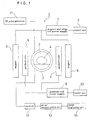
- Fig. 1 shows one example of the ultrahigh speed magnetic resonance imaging equipment for embodying this invention based on the principle of nuclear magnetic resonance.
- an MR imaging equipment 1 is furnished with an excitation and detection unit 2.
- the excitation and detection unit 2 demarcates a measuring region 3 and excites a substance 4 for measurement in the measuring region 3 as well.
- an RF pulse (excitation pulse) is supplied from an RF pulse generator 11. This RF pulse possesses a resonance frequency corresponding to the numerous points in the measuring region 3.
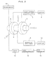
- a magnet 5 for generating static magnetic field and gradient coils 6 for generating gradient magnetic field are laid out in a planar state.
- the ultrahigh speed magnetic resonance imaging equipment shown in Fig. 2 represents an example which has a magnet 5 generating static magnetic field and gradient coils 6 generating gradient magnetic field in the magnet shown in Fig. 1.
- the magnet 5 is intended to generate a temporally and spatially specified magnetic field for an object to be imaged. It is preferred to form a static high magnetic field.
- a superconducting magnet and a permanent magnet, for example, are available therefore.
- the gradient coil 6 is a coil intended to generate a gradient magnetic field for temporally and spatially (G(w, y, z, t)) varying the magnetic field strength in the measuring region 3.
- G(w, y, z, t) varying the magnetic field strength in the measuring region 3.
- an electric current is supplied from a gradient magnetic field generating coil power source 9.
- the strength of the gradient magnetic field is decided in conformity with the width of the spectrum of a signal obtained by resonance, the spatial resolution and the size of the imaging region.
- the magnet 5 and the gradient coil 6 are respectively possessed of control units 8 and 10 which control the strengths of power source and magnetic field.
- the equipment is provided with the RF pulse generator 11 which serves to apply in a pulsated form a radiofrequency wave having a frequency ⁇ i equivalent to the resonance frequency.
- the excitation and detection unit 2 disposed in the periphery of an object to be imaged is observed to issue a signal (free induction decay signal or echo signal). This signal is acquired by a receiver 12.
- the signals which are subsequently observed are handled in accordance with the following method for temporal and spatial application of a gradient magnetic field so as to induce reconstruction of the spatial distribution and the temporal change of a magnetic resonance element in an imaging object as an image (two-dimensional [x, y] [x, y] or three-dimensional [x, y, z] image) by the use of a reconstruction unit 13.
- the reconstructed image inclusive of such chronological changes is displayed two-dimensionally [x, t], three-dimensionally [x, y, t] or four-dimensionally [x, y, z, t] by the image displaying unit 14.
- Fig. 3 illustrates a method for the applying the optimum gradient magnetic field for the sake of the two-dimensional [x, y] ultrahigh speed imaging.
- Fig. 3(a) shows the optimum trajectory during the data acquisition of the ultrahigh speed imaging of the motion of an object to be imaged and
- Fig. 3(b) shows the method for applying the optimum gradient magnetic field required for the imaging.
- the strength and the waveform of the trajectory and the corresponding gradient magnetic field to be applied are provided as optimized to suit the shape and the motion of an object to be imaged.
- Fig. 3 depicts the case of using the motion of five human fingers as an object to be imaged and assuming N to be 21 points.
- gradient magnetic fields in such magnitudes as shown in Fig. 3(b) to the X and Y directions so as to describe a trajectory shown in Fig. 3(a)
- the signal components having large amounts of data distributed on the trajectory and derived from the signals distributed in the k space can be observed in time series.
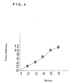
- the vertical axis is the scale of the difference in phase from the motion 1 of fingers.
- Fig. 4 shows the change in phase of an echo signal in the gripping motion of a human index finger.
- the motion of an object to be imaged can be continuously estimated as a phase difference indicated with a solid line in Fig. 4.
- the positions of the signals to be observed in the k space namely the trajectory in the k space (Fig. 3(a)) are obtained and the strengths of the gradient magnetic fields (Fig. 3(b)) to be applied during the course of imaging are decided based on the trajectory.
- the method for ultrahigh speed imaging proposed by this invention decreases the amount of data to be observed for the purpose of accomplishing an ultrahigh speed operation and reconstructs an image from the data.
- the motion is estimated by analyzing the changes in phase of the signals at the N points to be observed.
- the changes in phase of the data obtained in Fig. 5 are calculated based on Fig. 3.
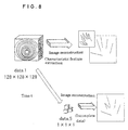
- a three-dimensional image is reconstructed by estimating the motion of an object to be imaged from the results obtained above and complementing the part lacking in the four data (data 2, data 3, data 4 and data 5) by using the two three-dimensional data (data 1 and data 6). Since it is only the data of the point N that is collected in the four data (data 2, data 3, data 4 and data 5) in the present example, this example attains addition to the speed of imaging and realizes ultrahigh speed magnetic resonance imaging.
- Fig. 6 through Fig. 9 show the procedures for imaging the grasping motion of five human fingers and the results of reconstruction of an image.
- Fig. 6 illustrates changes in phase of a signal in the k space obtained by computer simulation of a two-dimensional imaging.
- the object used for the imaging is a circle which is freely moved within the measuring region.
- the distributions of amplitude and phase of the signals obtained by imaging the object at varying times are varied at these times as shown in Fig. 6. Since the imaging object has an unchanged size, the individual amplitudes are not varied. In contrast, the phases are varied in conformity with the positions of the imaging object as shown in Fig. 7.
- the motion between the times T 0 and T 1 can be estimated from these changes in phase (differences in phase) as shown in Fig. 4.
- the imaging object is reconstructed as an image placed at the relevant intermediate position from the phase distribution of 1 ⁇ 2 of the phase difference and the amplitude.
- Fig. 6 depicts the results of the estimation of the imaging object at the varying intermediate positions ((T 0 + T 1 )/2) actually based on T 0 and T 1 .
- Fig. 7 depicts the results of subjecting the changes in phase of the signals observed during the motion of the imaging object within the measuring region to computer simulation (one-dimensional Fourier transformation).
- Fig. 7 shows the changes of the real number part and the imaginary number part of the k space obtained by assuming the changes in phase produced in consequence of the displacement in the one-dimensional direction and subjecting these changes individually to one-dimensional Fourier transformation
- Fig. 7(a) representing the case in which the data of 128 points (object to be imaged) existing at the center of the imaging region of 256 points is displaced by 32 pixels in the direction of right
- Fig. 7(b) the case in which they are displaced by 32 pixels in the direction of left. Since the imaginary number part is varied depending on the direction of displacement of the imagining object, the direction of displacement is known from the results of analyzing the changes in phase. In Fig. 7(a) and Fig. 7(b), for example, the changes occur in opposite directions.
- Fig. 8 is a three-dimensional image of five human fingers imaged and estimated on the basis of Fig. 5. It results from acquiring 128 by 128 by 128 pixels for data 1 and the data solely of the three points (1, 0, 0), (0, 1, 0) and (0, 0, 1) in the k space for the data 5, estimating and imaging the motions of data 1 and data 6, and acquiring reconfiguration.
- Fig. 9 shows the results of estimating the gripping motion of five human fingers in data 1 to data 6, complementing the actually imaged part, and subsequently reconstructing 11 continuous images, thereby obtaining a four-dimensional magnetic resonance image [x, y, z, t].
- the present results are characterized by enabling ultrahigh speed imaging because a four-dimensional image is reconstructed only by collecting 128 by 128 by 128 pixels for the data 1 and the data 6 and three pixels of data 5 from the data 2.
- a restraining condition is required to be introduced in estimating a motion of the imaging object.
- the ultrahigh speed magnetic resonance imaging equipment contemplated by this invention can be utilized for analyzing various materials, excluding metals and magnetic material, for internal structures and solid state properties (non-destructive examination); visualization of fluids; chemical structure and pharmacologic effect in pharmacy and chemistry; structural and functional analysis of living tissues in biology, medical diagnosis and physiology; and instrumentations of biological reactions and inspection and non-invasive diagnosis of diseases, for example.
Landscapes
- Physics & Mathematics (AREA)
- Health & Medical Sciences (AREA)
- General Health & Medical Sciences (AREA)
- Nuclear Medicine, Radiotherapy & Molecular Imaging (AREA)
- Radiology & Medical Imaging (AREA)
- Engineering & Computer Science (AREA)
- Signal Processing (AREA)
- High Energy & Nuclear Physics (AREA)
- Condensed Matter Physics & Semiconductors (AREA)
- General Physics & Mathematics (AREA)
- Magnetic Resonance Imaging Apparatus (AREA)
Applications Claiming Priority (3)
| Application Number | Priority Date | Filing Date | Title |
|---|---|---|---|
| JP2002159003 | 2002-05-31 | ||
| JP2002159003A JP2003339667A (ja) | 2002-05-31 | 2002-05-31 | 超高速磁気共鳴イメージング装置 |
| PCT/JP2003/006586 WO2003101293A1 (en) | 2002-05-31 | 2003-05-27 | Ultra high-speed magnetic resonance imaging device |
Publications (2)
| Publication Number | Publication Date |
|---|---|
| EP1550400A1 true EP1550400A1 (de) | 2005-07-06 |
| EP1550400A4 EP1550400A4 (de) | 2009-07-08 |
Family
ID=29706500
Family Applications (1)
| Application Number | Title | Priority Date | Filing Date |
|---|---|---|---|
| EP03733089A Withdrawn EP1550400A4 (de) | 2002-05-31 | 2003-05-27 | Magnetresonanztomograph mit ultrahochgeschwindigkeit |
Country Status (6)
| Country | Link |
|---|---|
| US (1) | US7505804B2 (de) |
| EP (1) | EP1550400A4 (de) |
| JP (1) | JP2003339667A (de) |
| AU (1) | AU2003241792A1 (de) |
| DE (1) | DE10392717T5 (de) |
| WO (1) | WO2003101293A1 (de) |
Cited By (1)
| Publication number | Priority date | Publication date | Assignee | Title |
|---|---|---|---|---|
| CN103809140A (zh) * | 2014-02-20 | 2014-05-21 | 厦门大学 | 基于单扫描超快速正交时空编码的小视野磁共振成像方法 |
Families Citing this family (2)
| Publication number | Priority date | Publication date | Assignee | Title |
|---|---|---|---|---|
| US20100145185A1 (en) * | 2008-12-04 | 2010-06-10 | Xiaole Hong | Extending the resolution of mri data by combining subsets from plural image acquisitions |
| US12000919B2 (en) * | 2022-08-26 | 2024-06-04 | Shanghai United Imaging Healthcare Co., Ltd. | Systems and methods for magnetic resonance imaging |
Family Cites Families (21)
| Publication number | Priority date | Publication date | Assignee | Title |
|---|---|---|---|---|
| US4579121A (en) * | 1983-02-18 | 1986-04-01 | Albert Macovski | High speed NMR imaging system |
| US4663591A (en) * | 1985-08-16 | 1987-05-05 | General Electric Company | Method for reducing image artifacts due to periodic signal variations in NMR imaging |
| US4949042A (en) * | 1988-01-22 | 1990-08-14 | Kabushiki Kaisha Toshiba | Magnetic resonance imaging system |
| JPH04246327A (ja) | 1991-01-31 | 1992-09-02 | Shimadzu Corp | ダイナミックmrイメージング法 |
| US5226418A (en) * | 1991-08-01 | 1993-07-13 | General Electric Company | Phase correction of complex - difference processed magnetic resonance angiograms |
| US5423315A (en) * | 1993-11-22 | 1995-06-13 | Picker International, Inc. | Magnetic resonance imaging system with thin cylindrical uniform field volume and moving subjects |
| US5657757A (en) * | 1995-08-17 | 1997-08-19 | General Electric Company | Interleaved MR spectroscopy and imaging with dynamically changing acquisition parameters |
| US5928146A (en) * | 1996-03-15 | 1999-07-27 | Hitachi Medical Corporation | Inspection apparatus using nuclear magnetic resonance |
| US5873825A (en) * | 1997-04-11 | 1999-02-23 | Wisconsin Alumni Research Foundation | Three dimensional digital subtraction magnetic resonance angiography with limited k-space mask |
| US6748098B1 (en) * | 1998-04-14 | 2004-06-08 | General Electric Company | Algebraic reconstruction of images from non-equidistant data |
| US6114852A (en) * | 1999-01-23 | 2000-09-05 | General Electric Company | Method employing point source to determine motion induced errors in MR imaging |
| JP3049607B1 (ja) | 1999-02-05 | 2000-06-05 | 技術研究組合医療福祉機器研究所 | 磁気共鳴撮影装置 |
| US20020002331A1 (en) * | 1999-05-14 | 2002-01-03 | Harvey Ellis Cline | Mr imaging with partial k-space acquisition using spiral scanning |
| US6560353B1 (en) * | 2000-03-21 | 2003-05-06 | Magnetic Resonance Innovations, Inc. | Method of MRI image reconstruction from partially acquired data in two or more dimensions using a multidimensional inverse transform technique |
| DE60132687T2 (de) * | 2000-03-27 | 2009-01-29 | Koninklijke Philips Electronics N.V. | Kernspin-verfahren zur bilderzeugung eines zeitabhängigen kontrastes |
| US6647134B1 (en) * | 2000-03-30 | 2003-11-11 | Mayo Foundation For Medical Education And Research | Autocorrection of MR projection images |
| US6411089B1 (en) * | 2000-11-22 | 2002-06-25 | Philips Medical Systems (Cleveland), Inc. | Two-dimensional phase-conjugate symmetry reconstruction for 3d spin-warp, echo-planar and echo-volume magnetic resonance imaging |
| US6518759B2 (en) * | 2001-04-09 | 2003-02-11 | Mayo Foundation For Medical Education And Research | Motion correction of magnetic resonance images |
| ATE404876T1 (de) * | 2001-11-12 | 2008-08-15 | Wisconsin Alumni Res Found | Dreidimensionale phasenkontrastmagnetresonanzabbildung mit verschachtelten projektions-rekonstruktions-daten |
| US6617850B2 (en) * | 2001-12-03 | 2003-09-09 | Mayo Foundation For Medical Education And Research | Motion correction of magnetic resonance images using phase difference of two orthogonal acquisitions |
| AU2003224377A1 (en) * | 2002-05-13 | 2003-11-11 | Koninklijke Philips Electronics N.V. | Prior-information-enhanced dynamic magnetic resonance imaging |
-
2002
- 2002-05-31 JP JP2002159003A patent/JP2003339667A/ja active Pending
-
2003
- 2003-05-27 DE DE10392717T patent/DE10392717T5/de not_active Withdrawn
- 2003-05-27 AU AU2003241792A patent/AU2003241792A1/en not_active Abandoned
- 2003-05-27 EP EP03733089A patent/EP1550400A4/de not_active Withdrawn
- 2003-05-27 US US10/515,186 patent/US7505804B2/en not_active Expired - Fee Related
- 2003-05-27 WO PCT/JP2003/006586 patent/WO2003101293A1/ja not_active Ceased
Non-Patent Citations (4)
| Title |
|---|
| See also references of WO03101293A1 * |
| TSAO J ET AL: "Prior-information-enhanced Dynamic Imaging using Single or Multiple Coils with k-t BLAST and k-t SENSE" INTERNATIONAL SOCIETY FOR MAGNETIC RESONANCE IN MEDICINE.SCIENTIFIC MEETING AND EXHIBITION. PROCEEDINGS, INTERNATIONAL SOCIETY FOR MAGNETIC RESONANCE IN MEDICINE, US, vol. 10, 18 May 2002 (2002-05-18), page 1, XP002248878 ISSN: 1524-6965 * |
| TSAO J ET AL: "Unifying linear prior-information-driven methods for accelerated image acquisition" MAGNETIC RESONANCE IN MEDICINE, ACADEMIC PRESS, DULUTH, MN, US, vol. 46, no. 4, 1 January 2001 (2001-01-01), pages 652-660, XP002248877 ISSN: 0740-3194 * |
| XIAOPING HU ET AL: "REDUCTION OF FIELD OF VIEW FOR DYNAMIC IMAGING" MAGNETIC RESONANCE IN MEDICINE, ACADEMIC PRESS, DULUTH, MN, US, vol. 32, no. 6, 1 June 1994 (1994-06-01), pages 691-694, XP000444469 ISSN: 0740-3194 * |
Cited By (2)
| Publication number | Priority date | Publication date | Assignee | Title |
|---|---|---|---|---|
| CN103809140A (zh) * | 2014-02-20 | 2014-05-21 | 厦门大学 | 基于单扫描超快速正交时空编码的小视野磁共振成像方法 |
| CN103809140B (zh) * | 2014-02-20 | 2016-04-20 | 厦门大学 | 基于单扫描超快速正交时空编码的小视野磁共振成像方法 |
Also Published As
| Publication number | Publication date |
|---|---|
| US7505804B2 (en) | 2009-03-17 |
| AU2003241792A1 (en) | 2003-12-19 |
| DE10392717T5 (de) | 2005-07-07 |
| EP1550400A4 (de) | 2009-07-08 |
| JP2003339667A (ja) | 2003-12-02 |
| WO2003101293A1 (en) | 2003-12-11 |
| US20050203376A1 (en) | 2005-09-15 |
Similar Documents
| Publication | Publication Date | Title |
|---|---|---|
| US5365172A (en) | Methods and apparatus for MRI | |
| US9111257B2 (en) | Medical imaging apparatus and control method thereof | |
| CN101336380B (zh) | 利用空间频率分析对诸如骨骼之类的结构的评估 | |
| EP1618843A1 (de) | Magnetresonanz-tomographie-verfahren und gerät | |
| JPH02140145A (ja) | 磁気共鳴イメージング装置 | |
| EP2461175A1 (de) | Magnetresonanzbildgebung mittels Mehrpunkt-Dixon-Technik | |
| EP2496954B1 (de) | MR-Bildgebung mithilfe von Navigatoren | |
| US8049497B2 (en) | MRI RF encoding using multiple transmit coils | |
| EP3591420B1 (de) | Verfahren und vorrichtung zur mrt-bildgebung mit magnetfeldmodulation | |
| JP6417406B2 (ja) | 強調磁化率コントラストによるmrイメージング | |
| US4567440A (en) | Vivo P-31 NMR imaging of phosphorus metabolites | |
| WO2014154544A1 (en) | Real-time motion correction for mri using fat navigators | |
| US7505804B2 (en) | Ultra high-speed magnetic resonance imaging device | |
| EP1803393A1 (de) | Vorrichtung und verfahren für die magnetresonanztomographie | |
| JP2009050738A (ja) | Mriデータの形成方法およびそれを用いたイメージング装置 | |
| JP5636058B2 (ja) | 磁気共鳴撮影装置 | |
| JP2018042671A (ja) | 磁気共鳴イメージング装置 | |
| EP3726239A1 (de) | Anfälligkeitsgewichtung durch phasenkontrast-mr-bildgebung | |
| US20110089949A1 (en) | Parallel Imaging Apparatus and Method | |
| EP4575541A1 (de) | Magnetresonanzbildgebung mit mehreren kontrasten | |
| JP2006087499A (ja) | Mriデータの形成方法およびそれを用いたイメージング装置 | |
| Müller-Bierl et al. | Numerical simulations of intra-voxel dephasing effects and signal voids in gradient echo MR imaging using different sub-grid sizes | |
| JP2007275481A (ja) | 磁気共鳴イメージング装置 | |
| Sekino et al. | Magnetic Resonance Imaging: Principles and Applications | |
| JP2014004012A (ja) | 磁気共鳴イメージング装置 |
Legal Events
| Date | Code | Title | Description |
|---|---|---|---|
| PUAI | Public reference made under article 153(3) epc to a published international application that has entered the european phase |
Free format text: ORIGINAL CODE: 0009012 |
|
| 17P | Request for examination filed |
Effective date: 20050103 |
|
| AK | Designated contracting states |
Kind code of ref document: A1 Designated state(s): AT BE BG CH CY CZ DE DK EE ES FI FR GB GR HU IE IT LI LU MC NL PT RO SE SI SK TR |
|
| AX | Request for extension of the european patent |
Extension state: AL LT LV MK |
|
| DAX | Request for extension of the european patent (deleted) | ||
| RBV | Designated contracting states (corrected) |
Designated state(s): NL TR |
|
| REG | Reference to a national code |
Ref country code: DE Ref legal event code: 8566 |
|
| A4 | Supplementary search report drawn up and despatched |
Effective date: 20090605 |
|
| RBV | Designated contracting states (corrected) |
Designated state(s): NL |
|
| 17Q | First examination report despatched |
Effective date: 20091019 |
|
| STAA | Information on the status of an ep patent application or granted ep patent |
Free format text: STATUS: THE APPLICATION HAS BEEN WITHDRAWN |
|
| 18W | Application withdrawn |
Effective date: 20100728 |