EP1550394B1 - Unité centrale d'aspiration - Google Patents
Unité centrale d'aspiration Download PDFInfo
- Publication number
- EP1550394B1 EP1550394B1 EP04028779A EP04028779A EP1550394B1 EP 1550394 B1 EP1550394 B1 EP 1550394B1 EP 04028779 A EP04028779 A EP 04028779A EP 04028779 A EP04028779 A EP 04028779A EP 1550394 B1 EP1550394 B1 EP 1550394B1
- Authority
- EP
- European Patent Office
- Prior art keywords
- cleaning system
- central vacuum
- vacuum cleaning
- wall
- holding plate
- Prior art date
- Legal status (The legal status is an assumption and is not a legal conclusion. Google has not performed a legal analysis and makes no representation as to the accuracy of the status listed.)
- Expired - Lifetime
Links
- 238000010407 vacuum cleaning Methods 0.000 title claims 28
- 239000000428 dust Substances 0.000 claims description 3
- 235000001674 Agaricus brunnescens Nutrition 0.000 claims 1
- 230000000149 penetrating effect Effects 0.000 claims 1
- 239000000725 suspension Substances 0.000 description 8
- XAGFODPZIPBFFR-UHFFFAOYSA-N aluminium Chemical compound [Al] XAGFODPZIPBFFR-UHFFFAOYSA-N 0.000 description 1
- 229910052782 aluminium Inorganic materials 0.000 description 1
- 230000005540 biological transmission Effects 0.000 description 1
- 230000003750 conditioning effect Effects 0.000 description 1
- 238000005553 drilling Methods 0.000 description 1
- 229920001971 elastomer Polymers 0.000 description 1
- 239000000806 elastomer Substances 0.000 description 1
- 238000003780 insertion Methods 0.000 description 1
- 230000037431 insertion Effects 0.000 description 1
- 238000009434 installation Methods 0.000 description 1
- 238000012986 modification Methods 0.000 description 1
- 230000004048 modification Effects 0.000 description 1
- 229910001220 stainless steel Inorganic materials 0.000 description 1
- 239000010935 stainless steel Substances 0.000 description 1
Images

Classifications
-
- A—HUMAN NECESSITIES
- A47—FURNITURE; DOMESTIC ARTICLES OR APPLIANCES; COFFEE MILLS; SPICE MILLS; SUCTION CLEANERS IN GENERAL
- A47L—DOMESTIC WASHING OR CLEANING; SUCTION CLEANERS IN GENERAL
- A47L9/00—Details or accessories of suction cleaners, e.g. mechanical means for controlling the suction or for effecting pulsating action; Storing devices specially adapted to suction cleaners or parts thereof; Carrying-vehicles specially adapted for suction cleaners
-
- A—HUMAN NECESSITIES
- A47—FURNITURE; DOMESTIC ARTICLES OR APPLIANCES; COFFEE MILLS; SPICE MILLS; SUCTION CLEANERS IN GENERAL
- A47L—DOMESTIC WASHING OR CLEANING; SUCTION CLEANERS IN GENERAL
- A47L5/00—Structural features of suction cleaners
- A47L5/12—Structural features of suction cleaners with power-driven air-pumps or air-compressors, e.g. driven by motor vehicle engine vacuum
- A47L5/22—Structural features of suction cleaners with power-driven air-pumps or air-compressors, e.g. driven by motor vehicle engine vacuum with rotary fans
- A47L5/38—Built-in suction cleaner installations, i.e. with fixed tube system to which, at different stations, hoses can be connected
-
- F—MECHANICAL ENGINEERING; LIGHTING; HEATING; WEAPONS; BLASTING
- F16—ENGINEERING ELEMENTS AND UNITS; GENERAL MEASURES FOR PRODUCING AND MAINTAINING EFFECTIVE FUNCTIONING OF MACHINES OR INSTALLATIONS; THERMAL INSULATION IN GENERAL
- F16M—FRAMES, CASINGS OR BEDS OF ENGINES, MACHINES OR APPARATUS, NOT SPECIFIC TO ENGINES, MACHINES OR APPARATUS PROVIDED FOR ELSEWHERE; STANDS; SUPPORTS
- F16M13/00—Other supports for positioning apparatus or articles; Means for steadying hand-held apparatus or articles
-
- F—MECHANICAL ENGINEERING; LIGHTING; HEATING; WEAPONS; BLASTING
- F16—ENGINEERING ELEMENTS AND UNITS; GENERAL MEASURES FOR PRODUCING AND MAINTAINING EFFECTIVE FUNCTIONING OF MACHINES OR INSTALLATIONS; THERMAL INSULATION IN GENERAL
- F16M—FRAMES, CASINGS OR BEDS OF ENGINES, MACHINES OR APPARATUS, NOT SPECIFIC TO ENGINES, MACHINES OR APPARATUS PROVIDED FOR ELSEWHERE; STANDS; SUPPORTS
- F16M13/00—Other supports for positioning apparatus or articles; Means for steadying hand-held apparatus or articles
- F16M13/02—Other supports for positioning apparatus or articles; Means for steadying hand-held apparatus or articles for supporting on, or attaching to, an object, e.g. tree, gate, window-frame, cycle
Definitions
- the invention relates to a central vacuum cleaner with a housing, an intake manifold, through which a suction channel leads, and a wall holding device by means of the central vacuum cleaner can be hung on a wall, wherein the wall holding means comprises a holding plate fixed to the housing and a wall holder to be fastened to the wall and on the holding plate and the wall holder nestable in one another connecting elements are arranged, wherein the intake manifold is arranged on the holding plate, wherein the suction passage passes through the holding plate.
- Central vacuum systems have a central vacuum, which is usually located in the basement of a building and from which a suction line system leads to Saugan gleichdosen in different rooms of the building.
- the connection to the suction line system via a connection piece of the central vacuum cleaner, which is fastened by means of a fastening part on the housing and is arranged over a suction inlet of the housing, so that a suction channel through the intake manifold leads into the interior of the housing of the central vacuum cleaner.
- Such central vacuum cleaner are usually hung on a building wall.
- a retaining plate is further attached to the housing of the central vacuum cleaner and attached to the wall, wherein the retaining plate and the wall holder nestable in one another fasteners, in particular hook elements can be arranged on the holding plate, which can be suspended in Einitatiö réelleen the wall holder.
- a contact plate is often attached to the housing in a region below the holding plate, which is supported in the suspended state of the central vacuum on a mounted on the wall in the area below the wall bracket system part.
- the U5 4,944,780 A and the U5 5,400,463 disclose generic central vacuum. In both of the intake is in one piece and thus immovably connected in its position relative to the housing with the housing.
- the object of the invention is to make the orientation of the intake manifold more flexible in generic central vacuum cleaners. According to the invention, this is achieved by a central vacuum cleaner with the features of claim 1.
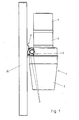
- the in Fig. 1 illustrated central vacuum cleaner has a housing 1, which comprises connectable housing parts 2, 3 and 4.
- a vacuum cleaner motor is arranged in the housing part 4.
- the housing part 3 contains a filter and the parts sucked in by the central vacuum cleaner reach into the dust receiving space contained in the housing part 2.
- the assembly 5 is mounted, which forms the device-fixed part of the wall-holding device.
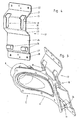
- the device-fixed unit 5 includes, as shown in particular from FIGS. 2 and 3 It can be seen, a holding plate 6 and a mounted on the support plate 6 intake 8.
- the support plate 6 is through holes 7 on the housing part 3 by means of screws 9 (see. Fig. 1 ) screwed.
- connection elements 10 which are designed as Ein vonmaschine, and support members 11 are arranged.
- the connecting elements 10 and the support members 11 are identical but rotated by 180 ° from each other.
- a suction channel 13 leads into the interior of the housing part 3, wherein the suction channel 13 passes through the holding plate 6.
- the longitudinal axis 14 of the intake manifold 8 closes with the holding plate 6 in its connection region with the intake manifold 8 an angle 15 of less than 60 °, preferably less than 45 °.
- the leading through the intake manifold 8 and the holding plate 6 suction channel 13 opens substantially tangentially in the cylindrical part in this area housing part 3. The sucked suction air can thereby straight and undisturbed entering the central vacuum, whereby both the loss of suction and the risk of clogging are minimized at this point.
- Suction tube (rigid or flexible) can be connected in a conventional manner, whereby the central vacuum cleaner is connected to the suction line.
- the holding plate 6 is curved to adapt to the outer contour of the housing part 3, in the illustrated embodiment thus seen in front view arcuate curved.
- a seal surrounding the suction channel 13 16 is mounted, whereby the suction channel 13 is performed in a sealed manner by the housing 1.
- the wall bracket 17 includes a curved plate having a support web 20 spaced from the wall. At its upper end in the mounting position of the support web 20 is connected via a connecting web 21 with a mounting bar 22 which is screwed through holes on the wall 25. At its lower end in mounting position of the support web 20 is connected via a connecting web 23 with a in the mounting position of the wall holder lower than the connecting web 23 and closer to the wall 25 lying (but distanced from the wall 25) support web 24.
- the plant parts 26 may consist of a suitable elastomer. Due to the elastic design of the system parts 26, in particular in conjunction with the relatively thin, somewhat resilient design of the plate of the wall holder 17, the transmission of structure-borne noise from the central vacuum cleaner to the wall 25 can be minimized.
- the plate of the wall holder 17 may be made of aluminum and have a thickness in the range of 2 to 3 mm or consist of stainless steel and have a thickness in the range between 1 and 2.5 mm.
- the narrower region 32 of the suspension opening is formed in the carrier web 20 and the suspension section extends over the uppermost part of the carrier web 20 and an adjoining part of the connecting web 21.
- the support web 24 is connected at its lower end in the mounting position via a connecting web 27 with a voltage applied to the wall mounting bar 28 which is screwed through holes on the wall 25.
- the connecting elements formed as Ein healthy tester 10 each have the shape of a pin with engaging grooves arranged thereon 29.
- the connecting elements 10 are inserted into the Ein vonskye 19 of the connecting elements 18 of the wall bracket, until they can be lowered into the narrower region 32 of the respective suspension opening, the edges of the suspension openings being inserted into the engagement grooves 29 in these narrower regions 32 of the suspension openings.
- these have anschl discloseend on the engagement grooves 29 widened portions 30 which are not feasible by the Ein stressedabête 19.
- the assembly 5 is in relation to a perpendicular to it and in the suspended state of the central vacuum cleaner horizontal plane 31, which in Fig. 3 is indicated by dashed lines, formed mirror-symmetrically.
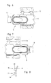
- a 180 ° about a horizontal, perpendicular to the surface of the housing 1 in the area between the connecting elements 10 and supporting parts 11 axis 12 twisted assembly of the unit 5 on the housing 1 allows, as can be seen the 6 and 7 is apparent.
- the axis 12 lies in the plane 31 and is substantially horizontal in the suspended state of the central vacuum.
- the intake manifold 8 can be aligned to the desired page.
- the intake manifold 8 extends laterally next to the connecting elements 10 and has with its free end away from them.
- the connecting elements 10 and the supporting parts 11 exchange their functions.
- the previously serving as support members 11 parts then serve as connecting elements and are hooked into the connecting elements 18, while the earlier fasteners 10 come to rest against the system components 26.
- connecting elements 10 (and therefore also the supporting parts 11) attached to the holding plate 6 could be formed in a mushroom-shaped manner with an enlarged head 33, as shown in FIG Fig. 6 is shown schematically in side view.
- the use of a larger or smaller number of connecting elements 10 or supporting parts 11 would also be conceivable and possible.
Landscapes
- Engineering & Computer Science (AREA)
- General Engineering & Computer Science (AREA)
- Mechanical Engineering (AREA)
- Electric Suction Cleaners (AREA)
- Nozzles For Electric Vacuum Cleaners (AREA)
Claims (20)
- Aspirateur central comportant un boîtier (1), un ajutage d'aspiration (8) traversé par un canal d'aspiration (13) et une installation de fixation murale pour accrocher l'aspirateur central à un mur (25),
l'installation de fixation murale se composant d'une plaque de fixation (6) fixée au boîtier (1) et un support mural (17) fixé au mur, et la plaque de fixation (6) et le support mural (17) comportant des éléments de liaison (10, 18) s'accrochant les uns dans les autres,
l'ajutage d'aspiration (8) étant prévu sur la plaque de fixation (6),
le canal d'aspiration (13) traversant la plaque de fixation (6),
caractérisé en ce qu'
une unité de construction (5), solidaire de l'appareil comprend la plaque de fixation (6) et l'ajutage d'aspiration (8) prévu sur la plaque de fixation (6),
l'unité de construction (5) étant montée sur le boîtier (1). - Aspirateur central selon la revendication 1,
caractérisé en ce que
dans la zone de jonction avec l'ajutage d'aspiration (8) l'axe longitudinal (14) de l'ajutage d'aspiration (8) fait, avec la plaque de fixation (6), un angle inférieur à 60° et de préférence inférieur à 45°. - Aspirateur central selon la revendication 2,
caractérisé en ce que
le canal d'aspiration (13) passant par l'ajutage d'aspiration (8) et la plaque de fixation (6) est pratiquement tangent dans cette zone au boîtier cylindrique (1). - Aspirateur central selon les revendications 1 à 3,
caractérisé en ce que
les éléments de liaison (10, 18) se composent d'au moins une pièce d'accrochage, de préférence d'au moins deux pièces d'accrochage et d'au moins un orifice d'accrochage, de préférence d'au moins deux orifices d'accrochage. - Aspirateur central selon la revendication 4,
caractérisé en ce qu'
au moins une pièce d'accrochage est prévue sur la plaque de fixation (6) et au moins un orifice d'accrochage est prévu sur le support mural (17). - Aspirateur central selon la revendication 4 ou 5,
caractérisé en ce qu'
au moins une pièce d'accrochage en forme de champignon est réalisée avec une tête agrandie s'accrochant dans l'orifice d'accrochage ou sous la forme d'un goujon muni d'une rainure d'engagement (29) dans laquelle pénètre le bord de l'orifice d'accrochage. - Aspirateur central selon la revendication 5 ou 6,
caractérisé en ce que
la plaque de fixation (6) comporte au moins une pièce d'appui (11) qui, lorsque l'aspirateur central est accroché au mur, s'appuie contre une pièce d'appui élastique (26) du support mural (17). - Aspirateur central selon les revendications 1 à 7,
caractérisé en ce que
l'unité de construction (5) comprenant, la plaque de fixation (6), l'ajutage d'aspiration (8) et les éléments de liaison (10), est symétrique par rapport à un plan perpendiculaire à la plaque de fixation (6) et horizontal lorsque l'aspirateur central est accroché au mur (31),
l'unité de construction (5) pouvant se monter sur le boîtier (1) de l'aspirateur central dans deux positions tournées l'une par rapport à l'autre de 180° autour d'un axe (12) situé dans ce plan (31) et horizontal lorsque l'aspirateur central est accroché au mur (25). - Aspirateur central selon la revendication 8,
caractérisé en ce que
dans les deux positions tournées de 180°, les fonctions d'au moins un élément de liaison (10) de la plaque de fixation (6) et d'au moins une pièce d'appui (11) de la plaque de fixation (6) sont inversées. - Aspirateur central selon les revendications 1 à 9,
caractérisé en ce que
la plaque de fixation présente une courbure adaptée à la zone de montage sur le boîtier (1). - Aspirateur central selon les revendications 1 à 10,
caractérisé en ce que
l'ajutage d'aspiration (8) passe à côté d'au moins un élément de liaison (10). - Aspirateur central selon les revendications 1 à 11,
caractérisé en ce que
le support mural comporte une plaque ayant une entretoise de support (20) écartée du mur (25) et par laquelle passe au moins un segment d'au moins un élément de liaison (18) réalisé comme orifice d'accrochage. - Aspirateur central selon la revendication 12,
caractérisé en ce qu'
une entretoise d'appui (24) est reliée à l'entretoise de support (20) par l'intermédiaire d'une entretoise de liaison (23), en position de montage du support mural (17) l'entretoise d'appui étant située plus bas que l'entretoise de liaison (21) et plus près du mur (25) que l'entretoise de liaison (21). - Aspirateur central selon la revendication 13,
caractérisé en ce qu'
au moins une pièce d'appui élastique (26) est prévue sur l'entretoise d'appui (24), pièce contre laquelle vient au moins une pièce d'appui (11) de la plaque de fixation (6) lorsque l'aspirateur central est en position accrochée au mur (25). - Aspirateur central selon les revendications 12 à 14,
caractérisé en ce que
l'entretoise de support (20) est reliée par une entretoise de liaison (21) à une entretoise de montage (22) vissée au mur, au moins un orifice d'accrochage s'étendant sur une partie de l'entretoise de liaison (21) en partant de l'extrémité supérieure de l'entretoise de support (20). - Aspirateur central selon les revendications 13 à 15,
caractérisé en ce que
l'entretoise d'appui (24) est écartée du mur (25) et elle est reliée par une entretoise de liaison (27) à une entretoise de montage (28) vissée au mur. - Aspirateur central selon les revendications 1 à 16,
caractérisé en ce que
la plaque de fixation (6) et l'ajutage d'aspiration (8) sont réalisés en une seule pièce. - Aspirateur central selon les revendications 1 à 17,
caractérisé en ce que
le boîtier (1) comprend des parties de boîtier (2, 3, 4) reliées l'une à l'autre et l'une des parties de boîtier (4) comporte un moteur d'aspirateur et l'une des parties de boîtier (3) comporte un filtre et l'une des parties de boîtier (3), une chambre de collecte de poussière dans laquelle débouchent les particules aspirées par l'aspirateur central. - Aspirateur central selon la revendication 18,
caractérisé en ce que
l'unité de construction (5) est montée sur la partie de boîtier (3) comportant le filtre. - Aspirateur central selon les revendications 1 à 19,
caractérisé en ce que
la plaque de fixation (6) est vissée par des vis dans des perçages (7) au boîtier (1) de préférence à la partie de boîtier (3) comportant la chambre de réception de poussière.
Applications Claiming Priority (2)
| Application Number | Priority Date | Filing Date | Title |
|---|---|---|---|
| AT0000204U AT7342U1 (de) | 2004-01-02 | 2004-01-02 | Zentralstaubsauger |
| AT204U | 2004-01-02 |
Publications (3)
| Publication Number | Publication Date |
|---|---|
| EP1550394A2 EP1550394A2 (fr) | 2005-07-06 |
| EP1550394A3 EP1550394A3 (fr) | 2007-05-09 |
| EP1550394B1 true EP1550394B1 (fr) | 2009-12-23 |
Family
ID=33494454
Family Applications (1)
| Application Number | Title | Priority Date | Filing Date |
|---|---|---|---|
| EP04028779A Expired - Lifetime EP1550394B1 (fr) | 2004-01-02 | 2004-12-04 | Unité centrale d'aspiration |
Country Status (3)
| Country | Link |
|---|---|
| EP (1) | EP1550394B1 (fr) |
| AT (2) | AT7342U1 (fr) |
| DE (1) | DE502004010544D1 (fr) |
Families Citing this family (2)
| Publication number | Priority date | Publication date | Assignee | Title |
|---|---|---|---|---|
| ITRA20070042A1 (it) * | 2007-06-01 | 2008-12-02 | Gen Aspirazione Di Bianchi Fa | Centralina per impianti aspirapolvere centralizzati . |
| CN113639372B (zh) * | 2021-07-05 | 2022-11-22 | 江西省源古宝健康管理有限公司 | 一种负离子空气净化器 |
Family Cites Families (4)
| Publication number | Priority date | Publication date | Assignee | Title |
|---|---|---|---|---|
| US3127629A (en) * | 1961-10-23 | 1964-04-07 | Filtex Corp | Built-in vacuum cleaning system |
| CA1313578C (fr) * | 1989-01-12 | 1993-02-16 | Kal Usmani | Aspirateur central avec filtre amovible |
| US5400463A (en) * | 1993-02-16 | 1995-03-28 | Beam Of Canada, Inc. | Noise dampened canister vacuum cleaner |
| DE20118467U1 (de) * | 2001-11-14 | 2002-02-21 | Schmitt, Robert, 97422 Schweinfurt | Elektrisch betriebene Saugeinheit für einen Staubsauger |
-
2004
- 2004-01-02 AT AT0000204U patent/AT7342U1/de not_active IP Right Cessation
- 2004-12-04 DE DE502004010544T patent/DE502004010544D1/de not_active Expired - Lifetime
- 2004-12-04 EP EP04028779A patent/EP1550394B1/fr not_active Expired - Lifetime
- 2004-12-04 AT AT04028779T patent/ATE452565T1/de active
Also Published As
| Publication number | Publication date |
|---|---|
| EP1550394A3 (fr) | 2007-05-09 |
| AT7342U1 (de) | 2005-02-25 |
| DE502004010544D1 (de) | 2010-02-04 |
| ATE452565T1 (de) | 2010-01-15 |
| EP1550394A2 (fr) | 2005-07-06 |
Similar Documents
| Publication | Publication Date | Title |
|---|---|---|
| DE102017109986B4 (de) | Anordnung von mehreren Sockellüftungsboxen für die Montage in einem Möbelsockel, ein Möbelsockel sowie eine entsprechende Downdraft-Dunstabzugsvorrichtung | |
| DE102012023734A1 (de) | Kreiselpumpe insbesondere für Abwasser oder Schmutzwasser | |
| WO1999000600A1 (fr) | Compresseur frigorifique | |
| DE202016005074U1 (de) | Filterpartrone und Filterpatronenanordnung | |
| DE202006005673U1 (de) | Abdeckvorrichtung für den vorderen Bereich einer Luftdurchtrittseinrichtung sowie Luftdurchtrittseinrichtung | |
| EP1550394B1 (fr) | Unité centrale d'aspiration | |
| DE202008002359U1 (de) | Befestigungsvorrichtung | |
| DE10036593A1 (de) | Luftfilter, insbesondere für die Ansaugluft einer Brennkraftmaschine | |
| WO2016071201A1 (fr) | Élément filtrant, en particulier pour la filtration de gaz | |
| DE202017100231U1 (de) | Befestigungsvorrichtung | |
| EP1698838B1 (fr) | Boîtier pour un dispositif de conduit d'air | |
| DE102020201557A1 (de) | Verdampfer | |
| AT509417B1 (de) | Vorrichtung zum befestigen einer funktionseinheit in einem möbelkorpus | |
| DE202012103038U1 (de) | Montagehalter für an Fenstern oder Türen abzuhängendes Sichtschutzzubehör und Fenster mit Montagehalter | |
| DE102021002350A1 (de) | Sammelvorrichtung für ein angetriebenes tragbares Werkzeug | |
| DE19944413B4 (de) | Klimatisierungseinrichtung | |
| DE20318350U1 (de) | Sauger zu Reinigungszwecken | |
| DE202020106912U1 (de) | Plattenartiges Trägerelement mit integriertem Duschkopfhalter | |
| EP0949953B1 (fr) | Socle commun pour un contenant de filtre et une pompe | |
| DE102017200514B4 (de) | Befestigungselement zur Festlegung eines Türantriebs an einer Profilschiene | |
| DE202017100805U1 (de) | Saugdüse | |
| DE20311470U1 (de) | Vorrichtung zur Deckenabhängung und Flächenentlüftung von Räumen | |
| DE9400970U1 (de) | Gehäuse für Klimageräte | |
| WO2003080387A1 (fr) | Accoudoir destine a des portieres de vehicules | |
| AT517980B1 (de) | Vorrichtung zum Lüften von Räumen |
Legal Events
| Date | Code | Title | Description |
|---|---|---|---|
| PUAI | Public reference made under article 153(3) epc to a published international application that has entered the european phase |
Free format text: ORIGINAL CODE: 0009012 |
|
| AK | Designated contracting states |
Kind code of ref document: A2 Designated state(s): AT BE BG CH CY CZ DE DK EE ES FI FR GB GR HU IE IS IT LI LT LU MC NL PL PT RO SE SI SK TR |
|
| AX | Request for extension of the european patent |
Extension state: AL BA HR LV MK YU |
|
| PUAL | Search report despatched |
Free format text: ORIGINAL CODE: 0009013 |
|
| AK | Designated contracting states |
Kind code of ref document: A3 Designated state(s): AT BE BG CH CY CZ DE DK EE ES FI FR GB GR HU IE IS IT LI LT LU MC NL PL PT RO SE SI SK TR |
|
| AX | Request for extension of the european patent |
Extension state: AL BA HR LV MK YU |
|
| RIC1 | Information provided on ipc code assigned before grant |
Ipc: F16M 13/02 20060101ALI20070402BHEP Ipc: A47L 5/38 20060101AFI20050412BHEP |
|
| 17P | Request for examination filed |
Effective date: 20070725 |
|
| 17Q | First examination report despatched |
Effective date: 20071018 |
|
| AKX | Designation fees paid |
Designated state(s): AT BE BG CH CY CZ DE DK EE ES FI FR GB GR HU IE IS IT LI LT LU MC NL PL PT RO SE SI SK TR |
|
| GRAP | Despatch of communication of intention to grant a patent |
Free format text: ORIGINAL CODE: EPIDOSNIGR1 |
|
| GRAS | Grant fee paid |
Free format text: ORIGINAL CODE: EPIDOSNIGR3 |
|
| GRAA | (expected) grant |
Free format text: ORIGINAL CODE: 0009210 |
|
| AK | Designated contracting states |
Kind code of ref document: B1 Designated state(s): AT BE BG CH CY CZ DE DK EE ES FI FR GB GR HU IE IS IT LI LT LU MC NL PL PT RO SE SI SK TR |
|
| REG | Reference to a national code |
Ref country code: GB Ref legal event code: FG4D Free format text: NOT ENGLISH |
|
| REG | Reference to a national code |
Ref country code: CH Ref legal event code: EP |
|
| REG | Reference to a national code |
Ref country code: IE Ref legal event code: FG4D |
|
| REF | Corresponds to: |
Ref document number: 502004010544 Country of ref document: DE Date of ref document: 20100204 Kind code of ref document: P |
|
| REG | Reference to a national code |
Ref country code: CH Ref legal event code: NV Representative=s name: RENTSCH & PARTNER |
|
| REG | Reference to a national code |
Ref country code: NL Ref legal event code: VDEP Effective date: 20091223 |
|
| PG25 | Lapsed in a contracting state [announced via postgrant information from national office to epo] |
Ref country code: SE Free format text: LAPSE BECAUSE OF FAILURE TO SUBMIT A TRANSLATION OF THE DESCRIPTION OR TO PAY THE FEE WITHIN THE PRESCRIBED TIME-LIMIT Effective date: 20091223 Ref country code: LT Free format text: LAPSE BECAUSE OF FAILURE TO SUBMIT A TRANSLATION OF THE DESCRIPTION OR TO PAY THE FEE WITHIN THE PRESCRIBED TIME-LIMIT Effective date: 20091223 Ref country code: FI Free format text: LAPSE BECAUSE OF FAILURE TO SUBMIT A TRANSLATION OF THE DESCRIPTION OR TO PAY THE FEE WITHIN THE PRESCRIBED TIME-LIMIT Effective date: 20091223 |
|
| LTIE | Lt: invalidation of european patent or patent extension |
Effective date: 20091223 |
|
| PG25 | Lapsed in a contracting state [announced via postgrant information from national office to epo] |
Ref country code: SI Free format text: LAPSE BECAUSE OF FAILURE TO SUBMIT A TRANSLATION OF THE DESCRIPTION OR TO PAY THE FEE WITHIN THE PRESCRIBED TIME-LIMIT Effective date: 20091223 Ref country code: PL Free format text: LAPSE BECAUSE OF FAILURE TO SUBMIT A TRANSLATION OF THE DESCRIPTION OR TO PAY THE FEE WITHIN THE PRESCRIBED TIME-LIMIT Effective date: 20091223 |
|
| REG | Reference to a national code |
Ref country code: IE Ref legal event code: FD4D |
|
| PG25 | Lapsed in a contracting state [announced via postgrant information from national office to epo] |
Ref country code: EE Free format text: LAPSE BECAUSE OF FAILURE TO SUBMIT A TRANSLATION OF THE DESCRIPTION OR TO PAY THE FEE WITHIN THE PRESCRIBED TIME-LIMIT Effective date: 20091223 Ref country code: NL Free format text: LAPSE BECAUSE OF FAILURE TO SUBMIT A TRANSLATION OF THE DESCRIPTION OR TO PAY THE FEE WITHIN THE PRESCRIBED TIME-LIMIT Effective date: 20091223 Ref country code: BG Free format text: LAPSE BECAUSE OF FAILURE TO SUBMIT A TRANSLATION OF THE DESCRIPTION OR TO PAY THE FEE WITHIN THE PRESCRIBED TIME-LIMIT Effective date: 20100323 Ref country code: ES Free format text: LAPSE BECAUSE OF FAILURE TO SUBMIT A TRANSLATION OF THE DESCRIPTION OR TO PAY THE FEE WITHIN THE PRESCRIBED TIME-LIMIT Effective date: 20100403 Ref country code: PT Free format text: LAPSE BECAUSE OF FAILURE TO SUBMIT A TRANSLATION OF THE DESCRIPTION OR TO PAY THE FEE WITHIN THE PRESCRIBED TIME-LIMIT Effective date: 20100423 Ref country code: IS Free format text: LAPSE BECAUSE OF FAILURE TO SUBMIT A TRANSLATION OF THE DESCRIPTION OR TO PAY THE FEE WITHIN THE PRESCRIBED TIME-LIMIT Effective date: 20100423 Ref country code: RO Free format text: LAPSE BECAUSE OF FAILURE TO SUBMIT A TRANSLATION OF THE DESCRIPTION OR TO PAY THE FEE WITHIN THE PRESCRIBED TIME-LIMIT Effective date: 20091223 |
|
| PG25 | Lapsed in a contracting state [announced via postgrant information from national office to epo] |
Ref country code: CZ Free format text: LAPSE BECAUSE OF FAILURE TO SUBMIT A TRANSLATION OF THE DESCRIPTION OR TO PAY THE FEE WITHIN THE PRESCRIBED TIME-LIMIT Effective date: 20091223 Ref country code: SK Free format text: LAPSE BECAUSE OF FAILURE TO SUBMIT A TRANSLATION OF THE DESCRIPTION OR TO PAY THE FEE WITHIN THE PRESCRIBED TIME-LIMIT Effective date: 20091223 |
|
| PG25 | Lapsed in a contracting state [announced via postgrant information from national office to epo] |
Ref country code: CY Free format text: LAPSE BECAUSE OF FAILURE TO SUBMIT A TRANSLATION OF THE DESCRIPTION OR TO PAY THE FEE WITHIN THE PRESCRIBED TIME-LIMIT Effective date: 20091223 Ref country code: GR Free format text: LAPSE BECAUSE OF FAILURE TO SUBMIT A TRANSLATION OF THE DESCRIPTION OR TO PAY THE FEE WITHIN THE PRESCRIBED TIME-LIMIT Effective date: 20100324 Ref country code: IE Free format text: LAPSE BECAUSE OF FAILURE TO SUBMIT A TRANSLATION OF THE DESCRIPTION OR TO PAY THE FEE WITHIN THE PRESCRIBED TIME-LIMIT Effective date: 20091223 |
|
| PLBE | No opposition filed within time limit |
Free format text: ORIGINAL CODE: 0009261 |
|
| STAA | Information on the status of an ep patent application or granted ep patent |
Free format text: STATUS: NO OPPOSITION FILED WITHIN TIME LIMIT |
|
| 26N | No opposition filed |
Effective date: 20100924 |
|
| PG25 | Lapsed in a contracting state [announced via postgrant information from national office to epo] |
Ref country code: DK Free format text: LAPSE BECAUSE OF FAILURE TO SUBMIT A TRANSLATION OF THE DESCRIPTION OR TO PAY THE FEE WITHIN THE PRESCRIBED TIME-LIMIT Effective date: 20091223 |
|
| PG25 | Lapsed in a contracting state [announced via postgrant information from national office to epo] |
Ref country code: IT Free format text: LAPSE BECAUSE OF FAILURE TO SUBMIT A TRANSLATION OF THE DESCRIPTION OR TO PAY THE FEE WITHIN THE PRESCRIBED TIME-LIMIT Effective date: 20091223 |
|
| BERE | Be: lapsed |
Owner name: WIEDEMANN, THOMAS Effective date: 20101231 |
|
| REG | Reference to a national code |
Ref country code: CH Ref legal event code: PFA Owner name: WIEDEMANN, THOMAS Free format text: WIEDEMANN, THOMAS#ST. MARTIN-STRASSE 2/27#A-6850 DORNBIRN (AT) -TRANSFER TO- WIEDEMANN, THOMAS#ST. MARTIN-STRASSE 2/27#A-6850 DORNBIRN (AT) |
|
| PG25 | Lapsed in a contracting state [announced via postgrant information from national office to epo] |
Ref country code: MC Free format text: LAPSE BECAUSE OF NON-PAYMENT OF DUE FEES Effective date: 20101231 |
|
| REG | Reference to a national code |
Ref country code: CH Ref legal event code: PL |
|
| GBPC | Gb: european patent ceased through non-payment of renewal fee |
Effective date: 20101204 |
|
| REG | Reference to a national code |
Ref country code: FR Ref legal event code: ST Effective date: 20110831 |
|
| PG25 | Lapsed in a contracting state [announced via postgrant information from national office to epo] |
Ref country code: BE Free format text: LAPSE BECAUSE OF NON-PAYMENT OF DUE FEES Effective date: 20101231 |
|
| PG25 | Lapsed in a contracting state [announced via postgrant information from national office to epo] |
Ref country code: FR Free format text: LAPSE BECAUSE OF NON-PAYMENT OF DUE FEES Effective date: 20110103 Ref country code: CH Free format text: LAPSE BECAUSE OF NON-PAYMENT OF DUE FEES Effective date: 20101231 Ref country code: LI Free format text: LAPSE BECAUSE OF NON-PAYMENT OF DUE FEES Effective date: 20101231 |
|
| REG | Reference to a national code |
Ref country code: DE Ref legal event code: R119 Ref document number: 502004010544 Country of ref document: DE Effective date: 20110701 |
|
| PG25 | Lapsed in a contracting state [announced via postgrant information from national office to epo] |
Ref country code: DE Free format text: LAPSE BECAUSE OF NON-PAYMENT OF DUE FEES Effective date: 20110701 Ref country code: GB Free format text: LAPSE BECAUSE OF NON-PAYMENT OF DUE FEES Effective date: 20101204 |
|
| PG25 | Lapsed in a contracting state [announced via postgrant information from national office to epo] |
Ref country code: LU Free format text: LAPSE BECAUSE OF NON-PAYMENT OF DUE FEES Effective date: 20101204 Ref country code: HU Free format text: LAPSE BECAUSE OF FAILURE TO SUBMIT A TRANSLATION OF THE DESCRIPTION OR TO PAY THE FEE WITHIN THE PRESCRIBED TIME-LIMIT Effective date: 20100624 |
|
| PG25 | Lapsed in a contracting state [announced via postgrant information from national office to epo] |
Ref country code: TR Free format text: LAPSE BECAUSE OF FAILURE TO SUBMIT A TRANSLATION OF THE DESCRIPTION OR TO PAY THE FEE WITHIN THE PRESCRIBED TIME-LIMIT Effective date: 20091223 |
|
| PGFP | Annual fee paid to national office [announced via postgrant information from national office to epo] |
Ref country code: AT Payment date: 20161213 Year of fee payment: 13 |
|
| REG | Reference to a national code |
Ref country code: AT Ref legal event code: MM01 Ref document number: 452565 Country of ref document: AT Kind code of ref document: T Effective date: 20171204 |
|
| PG25 | Lapsed in a contracting state [announced via postgrant information from national office to epo] |
Ref country code: AT Free format text: LAPSE BECAUSE OF NON-PAYMENT OF DUE FEES Effective date: 20171204 |