EP1549508B1 - Kugelschreiberspitze und verfahren zu ihrer herstellung - Google Patents
Kugelschreiberspitze und verfahren zu ihrer herstellung Download PDFInfo
- Publication number
- EP1549508B1 EP1549508B1 EP03761609.1A EP03761609A EP1549508B1 EP 1549508 B1 EP1549508 B1 EP 1549508B1 EP 03761609 A EP03761609 A EP 03761609A EP 1549508 B1 EP1549508 B1 EP 1549508B1
- Authority
- EP
- European Patent Office
- Prior art keywords
- ball
- opening
- tip
- flared portion
- housing
- Prior art date
- Legal status (The legal status is an assumption and is not a legal conclusion. Google has not performed a legal analysis and makes no representation as to the accuracy of the status listed.)
- Expired - Lifetime
Links
- 230000002093 peripheral effect Effects 0.000 claims description 16
- 238000004519 manufacturing process Methods 0.000 claims description 9
- 239000012530 fluid Substances 0.000 claims description 8
- 238000002788 crimping Methods 0.000 claims description 7
- 230000001154 acute effect Effects 0.000 claims description 4
- 239000002184 metal Substances 0.000 claims description 3
- 230000000717 retained effect Effects 0.000 claims description 3
- 238000009825 accumulation Methods 0.000 description 10
- 239000003292 glue Substances 0.000 description 5
- 238000012360 testing method Methods 0.000 description 4
- 230000015572 biosynthetic process Effects 0.000 description 3
- 208000031968 Cadaver Diseases 0.000 description 2
- 241001080024 Telles Species 0.000 description 2
- 230000000903 blocking effect Effects 0.000 description 2
- 230000003749 cleanliness Effects 0.000 description 2
- 239000002989 correction material Substances 0.000 description 2
- 238000001035 drying Methods 0.000 description 2
- 238000005096 rolling process Methods 0.000 description 2
- 238000007790 scraping Methods 0.000 description 2
- 230000035807 sensation Effects 0.000 description 2
- 241000895680 Stylosanthes guianensis Species 0.000 description 1
- 239000000654 additive Substances 0.000 description 1
- 238000004891 communication Methods 0.000 description 1
- 230000001419 dependent effect Effects 0.000 description 1
- 230000008021 deposition Effects 0.000 description 1
- 230000002542 deteriorative effect Effects 0.000 description 1
- 230000001627 detrimental effect Effects 0.000 description 1
- 230000008034 disappearance Effects 0.000 description 1
- 230000000694 effects Effects 0.000 description 1
- 238000003780 insertion Methods 0.000 description 1
- 230000037431 insertion Effects 0.000 description 1
- 239000007788 liquid Substances 0.000 description 1
- 238000003754 machining Methods 0.000 description 1
- 230000014759 maintenance of location Effects 0.000 description 1
- 238000012986 modification Methods 0.000 description 1
- 230000004048 modification Effects 0.000 description 1
- 230000000750 progressive effect Effects 0.000 description 1
- 230000002035 prolonged effect Effects 0.000 description 1
Images
Classifications
-
- B—PERFORMING OPERATIONS; TRANSPORTING
- B43—WRITING OR DRAWING IMPLEMENTS; BUREAU ACCESSORIES
- B43K—IMPLEMENTS FOR WRITING OR DRAWING
- B43K1/00—Nibs; Writing-points
- B43K1/08—Nibs; Writing-points with ball points; Balls or ball beds
Definitions
- the present invention relates to a ballpoint for a writing instrument according to the preamble of claim 1.
- the ball points of the aforementioned type are used for pen-type writing instruments, but also for writing instruments used to deposit on the paper a line of correction fluid or glue. However, when they are used, a fluid accumulation is obtained on the front face, and sometimes even on the lateral face of the tip body, which can cause soiling.
- the ink accumulated on the tip can also become detached during the writing movement which causes the deposition of a burr on the paper.
- the present invention aims to overcome the drawbacks mentioned above, by proposing a ball tip offering perfect cleanliness of use, without deteriorating the feeling of slippage of the tip on the paper or require an ink of particular composition s' it is a ballpoint pen.
- a further object of the invention is to avoid the blocking of the ball after a prolonged period of non-use.
- the subject of the invention is a ball point according to claim 1.
- the combination of the circumferential portion and the flared portion makes it possible to reduce in an entirely unexpected proportion the burrs and the accumulation of ink on the tip. Indeed, the tests carried out with ballpoint pens equipped with a tip according to the invention, no longer show smudges, even using a greasy ink which has the advantage of providing a good sensation of sliding of the tip. In the case of corrective fluid applicator type instruments or glue, the risk of blocking the ball is greatly reduced.
- the first points of ballpoint pens produced industrially had a front face of flared shape due to the crimping of the ball by a rolling operation of the tip body, operation in which the metal located at the periphery of the tip body was pushed forward more significantly than the metal adjacent to the ball.
- the major flaw of these first ball points was to cause many burrs.
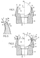
- a ballpoint 1 for a writing instrument and more particularly for a ballpoint pen, comprising a tip body 2.
- the left half-view of the figure 2 represents a raw tip body, while the right half-view shows the tip body after mounting a ball 3.
- the tip body 2 has a front face 4 and a shoulder 5 on which can be fitted a reservoir of ink not shown.
- the tip body 2 comprises a housing 6 which opens into an opening 7 formed in the front face 4.
- the housing 6 is substantially cylindrical and the opening 7 has a symmetry of revolution about a central axis Z which coincides with the axis of symmetry of the tip body.
- a passage 8 for supplying a fluid ensures communication between the ink reservoir and the housing 6.
- the ball 3 is freely rotatably mounted in the housing 6 and emerges through the opening 7.
- the ball 3 is retained by a seat 9 formed at the bottom of the housing 6 and the front end 10 of the wall of the tip body 2 which follows the contour of the ball.
- the tip body 2 is metallic in the embodiment shown, which makes it possible to obtain the bracing of the ball 3 by a crimping operation of the front end 10.
- the ball can not perform translational movement in the housing 6.
- the invention is also applicable to ball points comprising a spring disposed along the central axis Z which holds the ball against the front end 10 of the body peak.
- the seat 9 may comprise channels or fins that improve the passage of the ink from the supply passage 8 to the space 17, located between the ball and the seat, to ensure a uniform deposit of the ink on the ball.
- the front face 4 of the tip body has a peripheral portion 11 and, around the periphery of the opening 7, a flared portion 12.
- the peripheral portion 11 extends towards the central axis Z from the outer periphery of the front face 4, to the flared portion 12.
- the peripheral portion 11 is substantially parallel to the mean plane of the opening 7; in the embodiment shown, substantially perpendicular to the central axis Z.
- the flared portion is arranged so as to form, at the point of contact 13 of the ball 3 with the periphery of the opening 7, an acute angle ⁇ with the emergent part of the plane tangential to the ball at said contact point 13 and of which the trace T is visible on the figure 2 .
- peripheral portion 11 and the flared portion 12 makes it possible to significantly reduce the accumulation of ink on the front face 4, and the appearance of burrs on the paper.
- the tests show that with the ball tip having a flared portion according to the invention, there is no more burr deposit and this even with an ink containing no additives to limit the appearance of burrs. It is therefore possible to use a traditional fatty ink whose viscosity is greater than 40 poises. In addition, the other characteristics of the tip, such as writing comfort, are not degraded.
- the inventors filmed at high magnification the rolling of the ball 3 on a paper-like surface.
- the films show a progressive accumulation of the ink at a point of contact 13 between the ball and the front face 4, which is opposite to the driving direction.
- the accumulation of ink eventually forms a drop 18, as shown schematically on the figure 3 .
- this drop does not extend beyond the peripheral portion 11 and therefore, there is no ink deposit on the radially outer face of the tip body 2. It is also noted that the drop of does not detach from the front face 4 during a reversal of the direction of rotation of the ball, which explains the disappearance of the burrs. It is assumed that these phenomena are obtained by a slight drying of the portion 18a of the drop, which is located outwardly and therefore in contact with the air.
- the drop when the drop reaches a certain size, it collapses and disappears almost from the front face 4. This phenomenon can be explained by the presence of the flared portion 12 which forms with the wall of the ball 3 a funnel facilitating the return of the ink accumulated during the rotation of the ball.
- the portion 18b of the drop in contact with the ball 3 remains fluid due to the addition of fresh ink. The fluidity of the portion 18b certainly makes it possible to initiate the return of the ink.
- the ball tip according to the invention therefore makes it possible to confine an accumulation of ink and then to ensure its return to the tip body, unlike the ball points of the prior art, such as that shown on the half-view right of the figure 1 .
- the opening 7 of these anterior tips has a periphery 14 which forms an obtuse angle with the wall of the ball 3, which instead has the effect of scraping the ink present on the ball during its rotation and to retain the accumulation This ink accumulation can then be deposited on the paper, in particular during a change in the direction of rotation of the ball, and create a burr.
- the flared portion 12 is formed by a frustoconical surface coaxial with the central axis Z of the opening 7.
- This particular shape of the flared portion has the advantage of being able to be achieved with great precision, in particular with the manufacturing process described below.
- the angle ⁇ formed between the flared portion 12 and the emergent part of the tangent plane T is approximately 45 ° in the embodiment shown, but the flared portion 12 retains its role with an angle ⁇ varying between 30 ° and 70 ° .
- the tests show that with a ball of large diameter, for example 1.6 millimeters, it is sufficient that the axial height h of the frustoconical surface 12 is between 0.01 and 0.08 millimeters to prevent the appearance of burrs.
- the diameter of the ball may be smaller, up to 0.5 millimeters, or larger.
- the axial height h can then be varied proportionally so as to be between 0.6% and 5% of the diameter of the ball.
- the peripheral portion 11 has the shape of a circular ring due to the symmetry of revolution about the central axis Z of the tip body 2. This ring is flat before the production of the flared portion 12 by machining and the crimping of the ball 3, but it may be slightly deformed during these operations, and therefore the peripheral portion 11 may be only substantially flat when the ball point is complete.
- the peripheral portion 11 has a width l measured in a radial direction of the opening 7, that is to say along a perpendicular to the central axis Z.
- the width l must be sufficient to retain a drop of ink 18 without it reaching the outer periphery of the front face 4 and flowing on the radially outer wall of the tip body 2.
- the width 1 can be between 0.02 millimeter and 0.08 millimeter, that is to say between 1.2% and 5%. % of the diameter of the ball.
- a larger width of the peripheral portion 11 is of course conceivable, but it would increase the size of the tip body 2.
- the width l can be varied proportionally so as to be between 1.2% and 5% of the diameter of the ball. However, it is preferable that the width l be at least 0.01 millimeters to ensure the retention of an accumulation of ink.
- the axial height h of the flared portion 12 is substantially equal to the width 1 of the peripheral portion 11, which offers a good compromise between the cleanliness of the ball tip and the outside diameter of the face before 4.
- the ball point according to the invention can be made from a raw tip body identical to those used to manufacture the ball points of the prior art and shown on the left half view of the figure 1 .
- the housing 6 of this raw point body has a cylindrical front portion 15 which opens into an opening 7 at a right angle 16 with the front face 4 of the tip body 2.
- the periphery of the opening 7 is chamfered so as to eliminate the right angle 16, then the ball 3 is inserted into the housing 6 through the opening 7.
- the diameter of the ball 3 is more or less equal to the diameter of the cylindrical portion 15 of the housing 6 according to whether it is desired to obtain an insertion by force or soft friction and a more or less important space between the ball and the wall of the housing.
- the front end 10 of the tip body 2 is crimped against the ball so as to retain it in the housing 6. Thanks to the crimping, the inner wall of the front end 10 matches the wall of the ball leaving a determined space between these two walls.
- This manufacturing method has the advantage of being able to use the raw peak bodies of the prior art and requires only one additional step, the chamfering step, the other manufacturing steps being unchanged.
- the ball tip according to the invention can be produced in large series without profoundly modifying the production tool.
- peripheral portion and the flared portion may be adapted depending on the diameter of the ball or the thickness of the film present on the emergent portion of the ball, in particular in the case of a ball point for an applicator correction fluid or glue whose ball diameter can reach 3 millimeters.
Landscapes
- Pens And Brushes (AREA)
- Coating Apparatus (AREA)
- Cosmetics (AREA)
Claims (9)
- Kugelspitze für Schreibinstrument, umfassend:- einen Spitzenkörper (2), der eine Vorderseite (4) aufweist, wobei der Spitzenkörper eine Aufnahme umfasst (6), die in eine Öffnung (7) hineinragt, die in der Vorderseite (4) angeordnet ist und die mit einer Durchführung (8) zum Zuführen einer Flüssigkeit kommuniziert;- einen aufgeweiteten Abschnitt (12), der an die Außenlinie der Öffnung angrenzt; und- eine Kugel (3), die frei drehend in der Aufnahme (6) angeordnet ist und aus der Öffnung (7) herausragt,dadurch gekennzeichnet, dass die Vorderseite (4) des Spitzenkörpers (2) einen Umfangsabschnitt (11) umfasst, der sich bis zu dem aufgeweiteten Abschnitt (12) erstreckt und die Form eines im Wesentlichen flachen kreisförmigen Ringes hat und im Wesentlichen parallel zur Mittelebene der Öffnung ist, wobei der Umfangsabschnitt eine Breite I umfasst, die entlang einer radialen Richtung der Öffnung (7) gemessen mindestens 0,01 mm und mindestens 1,2% des Durchmessers der Kugel (3) beträgt, und dass der aufgeweitete Abschnitt (12) am Kontaktpunkt (13) zwischen der Kugel (3) und der Außenlinie der Öffnung mit dem herausragenden Abschnitt der Tangentialebene (T) der Kugel am Kontaktpunkt einen spitzen Winkel α bildet, der kleiner als 70° ist, wobei der aufgeweitete Abschnitt (12) eine Höhe h aufweist, die gemessen entlang einer Richtung, die rechtwinklig zur Mittelebene der Öffnung (7) verläuft, zwischen 0,6% und 5% des Durchmessers der Kugel beträgt.
- Kugelspitze nach Anspruch 1, dadurch gekennzeichnet, dass der Winkel α, der von dem aufgeweiteten Abschnitt (12) und dem herausragenden Bereich der Tangentialebene der Kugel (3) am Kontaktpunkt (13) zwischen der Kugel und der Außenlinie der Öffnung, 30 bis 70°beträgt, vorzugsweise im Wesentlichen 45°.
- Kugelspitze nach einem der Ansprüche 1 bis 2, dadurch gekennzeichnet, dass die Breite I zwischen 1,2% und 5% des Durchmessers der Kugel (3) beträgt.
- Kugelspitze nach Anspruch 3, dadurch gekennzeichnet, dass die axiale Höhe h des aufgeweiteten Abschnitts (12) im Wesentlichen der Breite (I) des Umfangabschnittes (11) entspricht.
- Kugelspitze nach einem beliebigen der Ansprüche 1 bis 4, dadurch gekennzeichnet, dass die Öffnung (7) des Spitzenkörpers (2) rotationssymmetrisch um eine zentrale Achse (Z) ist.
- Kugelspitze nach Anspruch 5, dadurch gekennzeichnet, dass der aufgeweitete Abschnitt (12) von einer kegelförmigen Oberfläche gebildet wird, die co-axial mit der zentralen Achse (Z) der Öffnung (7) ist.
- Kugelspitze nach einem beliebigen der Ansprüche 1 bis 6, dadurch gekennzeichnet, dass der Spitzenkörper (2) metallisch ist, und dass die Kugel (3) in der Aufnahme durch Pressen des spitzen Körpers gehalten wird.
- Kugelschreiber umfassend eine Kugelspitze nach einem beliebigen der Ansprüche 1 bis 7, dadurch gekennzeichnet, dass der Durchmesser der Kugel (3) zwischen 0,5 und 1,6 mm liegt, und dass die Tinte eine Viskosität größer als 40 Poises aufweist.
- Verfahren zur Herstellung einer Kugelspitze nach einem beliebigen der Ansprüche 1 bis 7, ausgehend von einem Rohspitzenkörper (2), der eine Vorderseite (4) umfasst und eine Aufnahme (6), deren zylindrischer vorderer Abschnitt (15) in eine Öffnung (7) hineinragt, die in der Vorderseite (4) ausgebildet ist, dadurch gekennzeichnet, dass:- ein aufgeweiteter Abschnitt (12) durch Anschrägen der Außenlinie der Öffnung (7) ausgebildet ist, wobei ein Bereich eines Umfangsabschnittes die Form eines flachen kreisförmigen Ringes hat,- eine Kugel (3), deren Durchmesser im Wesentlichen dem Durchmesser des zylindrischen Vorderabschnitts (15) der Aufnahme entspricht, durch die Öffnung (7) eingeführt wird;- der Spitzenkörper (2) ein vorderes Ende (10) umfasst, das derart gegen die Kugel (3) gepresst wird, dass diese in der Aufnahme (6) gehalten wird.
Applications Claiming Priority (3)
| Application Number | Priority Date | Filing Date | Title |
|---|---|---|---|
| FR0208189 | 2002-07-01 | ||
| FR0208189A FR2841497B1 (fr) | 2002-07-01 | 2002-07-01 | Pointe a bille pour instrument d'ecriture et son procede de fabrication |
| PCT/FR2003/001618 WO2004002750A1 (fr) | 2002-07-01 | 2003-05-28 | Pointe a bille pour instrument d'ecriture et son procede de fabrication |
Publications (2)
| Publication Number | Publication Date |
|---|---|
| EP1549508A1 EP1549508A1 (de) | 2005-07-06 |
| EP1549508B1 true EP1549508B1 (de) | 2013-07-31 |
Family
ID=29725036
Family Applications (1)
| Application Number | Title | Priority Date | Filing Date |
|---|---|---|---|
| EP03761609.1A Expired - Lifetime EP1549508B1 (de) | 2002-07-01 | 2003-05-28 | Kugelschreiberspitze und verfahren zu ihrer herstellung |
Country Status (10)
| Country | Link |
|---|---|
| US (1) | US6971814B2 (de) |
| EP (1) | EP1549508B1 (de) |
| JP (1) | JP4468168B2 (de) |
| CN (1) | CN100402312C (de) |
| AU (1) | AU2003249425C1 (de) |
| BR (1) | BR0312192B1 (de) |
| CA (1) | CA2488282C (de) |
| FR (1) | FR2841497B1 (de) |
| MX (1) | MXPA05000230A (de) |
| WO (1) | WO2004002750A1 (de) |
Families Citing this family (4)
| Publication number | Priority date | Publication date | Assignee | Title |
|---|---|---|---|---|
| DE102005054383B4 (de) | 2005-11-15 | 2013-10-31 | Boehringer Ingelheim Pharma Gmbh & Co. Kg | Nadel zum Lochen von Pulverkapseln für die Inhalation |
| US8261424B1 (en) * | 2006-08-31 | 2012-09-11 | Northwestern Tools, Inc. | Press-thru plunger and methods of manufacture and use |
| KR200470085Y1 (ko) * | 2008-01-31 | 2013-11-26 | 동아연필 주식회사 | 필기구용 팁 |
| TWI711770B (zh) * | 2019-02-27 | 2020-12-01 | 王鼎瑞 | 側向定位裝置 |
Family Cites Families (8)
| Publication number | Priority date | Publication date | Assignee | Title |
|---|---|---|---|---|
| BE471730A (de) * | 1945-01-19 | |||
| GB892624A (en) * | 1958-08-20 | 1962-03-28 | Hans Reinhard Fehling | Improvements in or relating to ballpointed writing instruments |
| US3380152A (en) * | 1965-10-18 | 1968-04-30 | Textron Inc | Writing implement |
| FR1576412A (de) * | 1968-04-08 | 1969-08-01 | ||
| DE2647225C3 (de) * | 1976-10-20 | 1981-12-10 | Fa. J.S. Staedtler, 8500 Nürnberg | Schreibspitze für Tintenkugelschreibgeräte |
| US6082920A (en) * | 1997-01-07 | 2000-07-04 | Mitsubishi Pencil Kabushiki Kaisha | Ball-point pen |
| WO2000069653A1 (fr) * | 1999-05-12 | 2000-11-23 | Premec Sa | Instrument pour l'ecriture |
| JP4363539B2 (ja) * | 1999-06-04 | 2009-11-11 | 諏訪熱工業株式会社 | ボールペン用ボール |
-
2002
- 2002-07-01 FR FR0208189A patent/FR2841497B1/fr not_active Expired - Fee Related
-
2003
- 2003-05-28 JP JP2004516834A patent/JP4468168B2/ja not_active Expired - Fee Related
- 2003-05-28 CA CA2488282A patent/CA2488282C/en not_active Expired - Fee Related
- 2003-05-28 WO PCT/FR2003/001618 patent/WO2004002750A1/fr not_active Ceased
- 2003-05-28 AU AU2003249425A patent/AU2003249425C1/en not_active Ceased
- 2003-05-28 MX MXPA05000230A patent/MXPA05000230A/es active IP Right Grant
- 2003-05-28 CN CNB038158655A patent/CN100402312C/zh not_active Expired - Fee Related
- 2003-05-28 BR BRPI0312192-5A patent/BR0312192B1/pt not_active IP Right Cessation
- 2003-05-28 EP EP03761609.1A patent/EP1549508B1/de not_active Expired - Lifetime
-
2004
- 2004-12-30 US US11/026,116 patent/US6971814B2/en not_active Expired - Fee Related
Also Published As
| Publication number | Publication date |
|---|---|
| BR0312192B1 (pt) | 2014-09-30 |
| AU2003249425B2 (en) | 2008-02-28 |
| EP1549508A1 (de) | 2005-07-06 |
| AU2003249425C1 (en) | 2008-09-18 |
| CA2488282C (en) | 2011-12-06 |
| MXPA05000230A (es) | 2005-04-11 |
| CN100402312C (zh) | 2008-07-16 |
| FR2841497A1 (fr) | 2004-01-02 |
| JP2005531437A (ja) | 2005-10-20 |
| FR2841497B1 (fr) | 2004-12-10 |
| CA2488282A1 (en) | 2004-01-08 |
| CN1665688A (zh) | 2005-09-07 |
| JP4468168B2 (ja) | 2010-05-26 |
| US6971814B2 (en) | 2005-12-06 |
| AU2003249425A1 (en) | 2004-01-19 |
| BR0312192A (pt) | 2005-04-26 |
| WO2004002750A1 (fr) | 2004-01-08 |
| US20050117961A1 (en) | 2005-06-02 |
Similar Documents
| Publication | Publication Date | Title |
|---|---|---|
| EP1549508B1 (de) | Kugelschreiberspitze und verfahren zu ihrer herstellung | |
| CA2389576C (fr) | Broche pour usiner des cannelures interieures de precision | |
| EP2349737A1 (de) | Ein aufschiebbares endglied umfassendes schreibgerät | |
| JP2008001008A (ja) | リフィール構成部材の接続構造 | |
| WO2006087444A1 (fr) | Embout pour pipette de prelevement, et pipette ainsi equipee | |
| WO1999038710A1 (fr) | Procede de fixation d'un ressort dans un corps creux | |
| EP3471882B1 (de) | Pipettiersystemspitze mit doppelter konizität | |
| FR2807353A1 (fr) | Pince de ravitaillement pour machine-outil | |
| EP3989771B1 (de) | Abstreifer für applikator flüssiger oder pastöser produkte | |
| EP1472101B1 (de) | Schreibgerät mit schreibspitzenstützmittel | |
| EP0923456B1 (de) | Kugelspitze für kugelschreiber | |
| WO2000069653A1 (fr) | Instrument pour l'ecriture | |
| JP4893418B2 (ja) | ボールペンチップの製造方法 | |
| JP4267886B2 (ja) | 塗布具用チップ、塗布具及び塗布具用チップの製造方法 | |
| EP4431858A1 (de) | Choke für gewehrlauf und verfahren zur modifizierung eines chokes | |
| JP6633363B2 (ja) | ボールペンチップ及び該ボールペンチップの製造方法並びに該ボールペンチップを具備した筆記具 | |
| FR3162163A1 (fr) | Instrument d’écriture | |
| EP0571297A1 (de) | Geschlitzte Haltehülse und Verfahren zu ihrer Herstellung | |
| BE564647A (de) | ||
| JP2006334866A (ja) | ボールペンチップ | |
| JP2006334867A (ja) | ボールペンチップ | |
| BE599713A (de) |
Legal Events
| Date | Code | Title | Description |
|---|---|---|---|
| PUAI | Public reference made under article 153(3) epc to a published international application that has entered the european phase |
Free format text: ORIGINAL CODE: 0009012 |
|
| 17P | Request for examination filed |
Effective date: 20041130 |
|
| AK | Designated contracting states |
Kind code of ref document: A1 Designated state(s): AT BE BG CH CY CZ DE DK EE ES FI FR GB GR HU IE IT LI LU MC NL PT RO SE SI SK TR |
|
| AX | Request for extension of the european patent |
Extension state: AL LT LV MK |
|
| DAX | Request for extension of the european patent (deleted) | ||
| RBV | Designated contracting states (corrected) |
Designated state(s): DE ES FR GB |
|
| GRAP | Despatch of communication of intention to grant a patent |
Free format text: ORIGINAL CODE: EPIDOSNIGR1 |
|
| GRAS | Grant fee paid |
Free format text: ORIGINAL CODE: EPIDOSNIGR3 |
|
| GRAA | (expected) grant |
Free format text: ORIGINAL CODE: 0009210 |
|
| PUAC | Information related to the publication of a b1 document modified or deleted |
Free format text: ORIGINAL CODE: 0009299EPPU |
|
| AK | Designated contracting states |
Kind code of ref document: B1 Designated state(s): DE ES FR GB |
|
| REG | Reference to a national code |
Ref country code: GB Ref legal event code: FG4D Free format text: NOT ENGLISH |
|
| STAA | Information on the status of an ep patent application or granted ep patent |
Free format text: STATUS: THE APPLICATION HAS BEEN WITHDRAWN |
|
| DB1 | B1 document deleted | ||
| 18W | Application withdrawn |
Effective date: 20130718 |
|
| REG | Reference to a national code |
Ref country code: DE Ref legal event code: R096 Ref document number: 60344621 Country of ref document: DE Effective date: 20130926 |
|
| REG | Reference to a national code |
Ref country code: DE Ref legal event code: R107 Ref document number: 60344621 Country of ref document: DE Effective date: 20131031 |