EP1549474B1 - Casting mould for cylindrical cast resin coils - Google Patents
Casting mould for cylindrical cast resin coils Download PDFInfo
- Publication number
- EP1549474B1 EP1549474B1 EP03757679A EP03757679A EP1549474B1 EP 1549474 B1 EP1549474 B1 EP 1549474B1 EP 03757679 A EP03757679 A EP 03757679A EP 03757679 A EP03757679 A EP 03757679A EP 1549474 B1 EP1549474 B1 EP 1549474B1
- Authority
- EP
- European Patent Office
- Prior art keywords
- casting
- mold
- connection
- mold casing
- casing
- Prior art date
- Legal status (The legal status is an assumption and is not a legal conclusion. Google has not performed a legal analysis and makes no representation as to the accuracy of the status listed.)
- Expired - Fee Related
Links
Images
Classifications
-
- B—PERFORMING OPERATIONS; TRANSPORTING
- B29—WORKING OF PLASTICS; WORKING OF SUBSTANCES IN A PLASTIC STATE IN GENERAL
- B29C—SHAPING OR JOINING OF PLASTICS; SHAPING OF MATERIAL IN A PLASTIC STATE, NOT OTHERWISE PROVIDED FOR; AFTER-TREATMENT OF THE SHAPED PRODUCTS, e.g. REPAIRING
- B29C33/00—Moulds or cores; Details thereof or accessories therefor
- B29C33/0011—Moulds or cores; Details thereof or accessories therefor thin-walled moulds
-
- B—PERFORMING OPERATIONS; TRANSPORTING
- B29—WORKING OF PLASTICS; WORKING OF SUBSTANCES IN A PLASTIC STATE IN GENERAL
- B29C—SHAPING OR JOINING OF PLASTICS; SHAPING OF MATERIAL IN A PLASTIC STATE, NOT OTHERWISE PROVIDED FOR; AFTER-TREATMENT OF THE SHAPED PRODUCTS, e.g. REPAIRING
- B29C33/00—Moulds or cores; Details thereof or accessories therefor
- B29C33/30—Mounting, exchanging or centering
- B29C33/306—Exchangeable mould parts, e.g. cassette moulds, mould inserts
-
- B—PERFORMING OPERATIONS; TRANSPORTING
- B29—WORKING OF PLASTICS; WORKING OF SUBSTANCES IN A PLASTIC STATE IN GENERAL
- B29C—SHAPING OR JOINING OF PLASTICS; SHAPING OF MATERIAL IN A PLASTIC STATE, NOT OTHERWISE PROVIDED FOR; AFTER-TREATMENT OF THE SHAPED PRODUCTS, e.g. REPAIRING
- B29C33/00—Moulds or cores; Details thereof or accessories therefor
- B29C33/30—Mounting, exchanging or centering
- B29C33/308—Adjustable moulds
-
- H—ELECTRICITY
- H01—ELECTRIC ELEMENTS
- H01F—MAGNETS; INDUCTANCES; TRANSFORMERS; SELECTION OF MATERIALS FOR THEIR MAGNETIC PROPERTIES
- H01F41/00—Apparatus or processes specially adapted for manufacturing or assembling magnets, inductances or transformers; Apparatus or processes specially adapted for manufacturing materials characterised by their magnetic properties
- H01F41/02—Apparatus or processes specially adapted for manufacturing or assembling magnets, inductances or transformers; Apparatus or processes specially adapted for manufacturing materials characterised by their magnetic properties for manufacturing cores, coils, or magnets
- H01F41/04—Apparatus or processes specially adapted for manufacturing or assembling magnets, inductances or transformers; Apparatus or processes specially adapted for manufacturing materials characterised by their magnetic properties for manufacturing cores, coils, or magnets for manufacturing coils
- H01F41/12—Insulating of windings
- H01F41/127—Encapsulating or impregnating
-
- B—PERFORMING OPERATIONS; TRANSPORTING
- B29—WORKING OF PLASTICS; WORKING OF SUBSTANCES IN A PLASTIC STATE IN GENERAL
- B29C—SHAPING OR JOINING OF PLASTICS; SHAPING OF MATERIAL IN A PLASTIC STATE, NOT OTHERWISE PROVIDED FOR; AFTER-TREATMENT OF THE SHAPED PRODUCTS, e.g. REPAIRING
- B29C33/00—Moulds or cores; Details thereof or accessories therefor
- B29C33/30—Mounting, exchanging or centering
-
- B—PERFORMING OPERATIONS; TRANSPORTING
- B29—WORKING OF PLASTICS; WORKING OF SUBSTANCES IN A PLASTIC STATE IN GENERAL
- B29C—SHAPING OR JOINING OF PLASTICS; SHAPING OF MATERIAL IN A PLASTIC STATE, NOT OTHERWISE PROVIDED FOR; AFTER-TREATMENT OF THE SHAPED PRODUCTS, e.g. REPAIRING
- B29C33/00—Moulds or cores; Details thereof or accessories therefor
- B29C33/38—Moulds or cores; Details thereof or accessories therefor characterised by the material or the manufacturing process
Definitions
- the invention relates to a casting mold for cylindrical cast resin coils, which extends along an axis, with an outer, formed with a tubular bent mold shell wall molding shell, which surrounds a cylindrical casting chamber and with a filling gap, through which the casting space can be filled with casting resin, wherein the casting shell can be separated with a detachable connection in the axial direction.
- Such a mold is from the German patent DE 44 26 138 C2 known.
- the releasable connection serves to be able to control a coil which is already in the casting mold and is still to be cast in with casting resin in the region of its coil terminals before pouring.
- the mold shell wall is movable and hinged when dissolved connection, so that the casting room is accessible there.
- the mold shell of the known mold has a G confuseharzein hypoxiatutzenteil formed with the G mantelwand in which the G manformmantelwand is bent at their axially facing edges each over its entire axial length at an angle to the outside, so that two outwardly facing Ein colllstutzenfound are formed ,
- the already tubular pre-bent mold shell wall is wrapped around the coil so that the G tellharzein Stahl is formed, so facing the two filler neck walls leaving the filling gap.
- the outer circumference of the casting space and thus the outer circumference of the casting resin coil is determined by the length of the casting shell wall. In that regard, different shapes are required for coils with different outer diameters, in which the casting shell walls have different lengths.
- the object of the invention is to provide a mold of the type mentioned, which allows a casting of coils with different outer circumference with relatively little effort.
- a G mantelverinrungsteil is provided which is designed such that it can be used at the split connection for extending the mold shell in the mold shell.
- the mold shell can be extended and thus set a larger outer circumference, so that casting molds can be produced with at least two different outer diameters with the mold according to the invention.
- the G confuseformmantelverinrungsteil is formed insertable into the mold shell, the G confuseformmantelverinrungsteil can be used with very little effort in the mold shell and removed again.
- here are not two complete molds, but only the mold according to the invention with the G intelligentformmantelverdorfrungsteil required to produce coils with different outer diameter can.
- a low cost arises in particular from the fact that the G recognizeformverdorfrungsteil has much smaller dimensions than a complete mold.
- the compound with which the casting shell can be separated in the axial direction can be, for example, a screw connection.
- the compound is a hook connection.
- the mold shell can be separated by simply hooking the releasable connection and closed by appropriate hooking again.
- the mold connection jacket extension part can be used in the mold shell in which it is hooked accordingly.
- the casting shell wall is in each case correspondingly bent back at its edges forming the connection, which are directed in the axial direction, such that the edges can be hooked to one another.
- the hook connection can thus be formed particularly easily by hooking the edges together.
- the G tellformmantelverinrungsteil is thin-walled and formed of such a resilient material that it is bent for insertion into the mold shell against a spring force, which causes when singling the G tellformmantelverinrungsteils its return springs to a substantially flat plate.
- the mold jacket extension part if it is not used in the mold shell, always as a substantially flat plate before, which is particularly space-saving and easy to store.
- This has a particularly advantageous effect on a variety of G tellmantelweitfit réelles negligence with different dimensions, which are provided for converting the mold for a variety of different outer diameters.
- the plurality G mantelverdorfggedsmaschine can then be easily stored, since they are each largely flat and therefore require little space.
- the mold shell on a over the entire axial mold length extending G fauxformein spallstutzenteil with the filling gap wherein the G manformeinhell Mnteil is completely detachable from the mold shell wall via the one releasable connection and another releasable connection.
- the entire casting shell wall against another, in its the outer circumference of the casting room-determining length to a casting shell wall different further G confuseformmantelwand instead of a casting shell wall are connected to the G confuseformein spallstutzenteil.
- the invention also relates to a mold for cylindrical cast resin coils extending along an axis, comprising an outer mold shell surrounding a cylindrical casting region and substantially defining the outer periphery of the casting space, the casting shell having a tubular bent shell wall and a mold shell wall connected, over the entire axial length of the mold shell extending G confuseharzein Stahl over which the casting chamber can be filled with resin, wherein the mold shell can be separated with a releasable connection in the axial direction.
- Object of the invention is also to provide a mold of the type mentioned, which allows a casting of coils with different outer circumference with relatively little effort.
- the object is achieved in a casting mold of the aforementioned type according to the invention in that the mold shell has a further releasable connection with the mold shell is separable in the axial direction and the compounds are arranged such that the G stealharzein Stahl is separable from the mold shell wall, said Connections are designed as Hakthetic.
- the mold shell wall in the mold according to the invention is easily interchangeable with another mold shell wall with a different length, in which the two compounds are solved, which removes a G stealformmantelwand and in their place, which are built up to the outer circumference determining length identical other G mantelwand.
- the mold according to the invention can be easily converted to a cast resin coil with a different outer diameter produce and it is also here not two complete molds required, so that there is a lesser effort here.
- the G tellharzein hypothaliana has at least one part jacket wall, which is verhakbar with the G manformmantelwand to form the at least one compound, wherein the G manformmantelwand at its axially directed, the at least one compound forming edge is bent back and
- the connection forming part jacket wall edge corresponding to the connection forming edge of the casting shell wall is bent back.
- a further casting shell wall is provided with an opposite to a casting shell wall, the outer periphery of the casting space defining edge length for replacement against a casting shell wall.
- the outer periphery of the casting space can be formed by a simple replacement of a casting shell wall against the other shell wall mold with little effort, another mold, which has a different outer circumference of the casting chamber with respect to the mold with a mold shell wall formed a different outer circumference.
- the mold shell wall is formed of such a resilient material that the mold shell wall is bent for connection to the G confuseharzein Stahl against a spring force, which causes the singling of the mold shell wall their spring back to a substantially flat plate.
- the casting shell extension part namely that the casting shell wall, insofar as it is not used for the formation of the casting mold, can be stored particularly well, since it is present as a substantially flat plate.
- the mold filler neck part is advantageously designed such that the width of the filling gap is adjustable.
- the outer circumference of the casting space can be adjusted particularly fine here by slightly changing the width of the filling gap.
- the G hassleharzein colllstutzenteil preferably has two almost over the entire axial mold length extending, angled outwardly projecting Ein colllstutzentown, which are spaced apart from each other via the filling gap and which are connected via at least one spacer element, the width of the filling gap is determined by the element width.
- the width of the filling gap can be particularly simple by replacing the spacer element with another Distance element can be set with a different fixed element width.
- the element width of the spacer element is adjustable. As a result, without an exchange of the spacer element whose element width and thus the width of the filling gap can be adjusted.
- This embodiment has the advantage that the pouring space can be completed particularly easily for the front face with the same end face also for different outer diameter of the pouring space set over the casting mold shell.
- the casting chamber is sealed at the closing end face with a seal.
- leakage of cast resin during filling of the casting mold at the closing end face is advantageously avoided.
- the seal surrounds the mold shell.
- the seal may be formed, for example, as a U-profile that the front side are slipped over the G mantelwand and the corresponding walls of the G mantelwand and the corresponding walls of the G mantelwands, in which case the mold jacket rests on the seal on the final face.
- Such a seal is available as a commodity and therefore very inexpensive.
- each connection is sealed with a gasket.
- a gasket for sealing, for example, a corresponding sealing compound or a rubber seal or a corresponding sealing foam may be provided.
- the casting shell has an overlap wall part which overlaps the one connection on the inside in the circumferential direction.
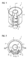
- FIG. 1 shows a casting mold 1 extending along an axis 4, which has an outer casting shell 2 formed with a tubular bent casting shell wall 3 and a casting filler neck part 6.
- the casting shell 2 surrounds a cylindrical casting chamber 7 whose outer circumference coincides with the inner side 8 of the casting shell 2 and is accordingly defined by the casting shell 2.
- the casting mold 1 also has a casting mold 5 which delimits the casting space 7 inwards.
- the casting shell 2 has a filling gap 9, via which the casting region 7 can be filled with a casting resin.
- the casting shell 2 has a first connection 10 schematically indicated by a line, via which the casting shell 2 can be detachably separated in the axial direction.
- the mold shell 2 has a second, also schematically indicated with a line releasable connection 11, which also serves the axial separation of the mold shell 2.
- the execution of the two detachable connections 10 and 11 is in the description of the Figures 2 and 7 explained in more detail.
- the G hassleformein spallstutzenteil 6 has a first and a second partial jacket wall 12 and 13, via which it is connected to the mold shell wall 3 at the detachable connections 10 and 11, respectively.
- the G manformein spallstutzenteil 6 further comprises two over the entire axial mold length extending and angled outwardly projecting Ein colllstutzenstate 14 and 15, which are connected to the partial casing walls 12 and 13 respectively.
- the filler neck walls 14 and 15 are spaced apart from one another via the filling gap 9 and connected via spacer elements 16, 17 and 18.
- the spacer elements 16 to 18 all have a same element width 19 (see FIG. 2 ), over which the width 20 (see FIG. 2 ) of the filling gap is fixed.
- the spacer elements 16 to 18 may be formed with a fixed element width 19. In the present case, however, the element width 19 of the spacer elements 16 to 19 can be varied, as will be explained below (see FIG. 3 ).
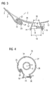
- FIG. 2 is a plan view of the mold 1 according to FIG. 1 shown.
- the two compounds 10 and 11 are in the present case designed as Haktagenen.
- the structure of the hook connections 10 and 11 is in FIG. 3 explained in more detail, where the connection 10 is shown in an enlarged view.
- the mold shell wall 3 and the part jacket wall 12 are hooked together formed.
- the casting shell wall 3 is bent back in the area at its edge 22 oriented in the axial direction.
- the partial jacket wall 12 is bent back corresponding to the edge 22 in the area at its partial jacket wall edge 23 which is directed in the axial direction, so that the partial jacket wall 12 and the casting shell wall 3 intermesh at their edges 22 and 23.
- a correspondingly inserted seal 24 which may be formed for example as a rubber band and corresponding to the course of the partial shell wall 12 and the casting shell wall 3 at the partial shell wall edge 23 and edge 22 is bent in accordance S-shaped ,
- the mold shell 2 may have an indicated by dashed lines overlap wall 25, the connection 10 inside in the circumferential direction overlaps. present If the overlapping wall is connected to the partial jacket wall 12 of the filler neck part 6, it may also instead be connected to the casting shell wall 3.
- the width 16 of the filling gap 9 is over the element widths of the spacer elements, of which in FIG. 3 only the spacer element 16 is shown with its element width 19 set.
- the element width 19 of the spacer element 16 can be changed.
- the spacer element 16 has for this purpose connected to the filler neck wall 14 sleeve nut 47, into which a screw 48 is screwed. The further the screw 48 is screwed into the sleeve nut 47, the shorter the element width 19 of the spacer element 16. By correspondingly far screwing the screw 48 into the sleeve nut 47 thus the element length 19 and thus the width 20 of the filling gap 9 can be changed.
- FIG. 4 is one to FIG. 2 Corresponding plan view of a relative to the mold 1 according to FIG. 1 modified mold 26 shown.
- the casting mold 26 has a casting shell 28 formed with a casting shell wall 27.
- the casting shell 28 surrounds a cylindrical casting region 34, the outer periphery of which coincides with the inner side 35 of the casting shell 28, insofar the outer circumference is defined here by the casting shell 28.
- the casting shell wall 28 can be separated in the axial direction at a detachable connection 29 corresponding to the connection 10 of the casting mold 1.
- the casting shell 28 has a compared to the G manformein spallstutzenteil 6 modified G cordformein spallstutzenteil 30 which is not completely separated from the casting shell wall 27, because no further, the compound 11 according to the mold 1 corresponding releasable connection is provided.
- the G manformein spallstutzenteil 30 also has two filler neck walls 31 and 32 which correspond to the filler neck walls 14 and 15 of the filler neck 6 of the mold 1.
- the filler neck walls 31 and 32 are the same as the filler neck walls 14 and 15 of the mold 1 connected via spacer elements, wherein in the present case only one spacer element 33 is shown due to the view.
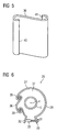
- a G tellformmantelverinrungsteil 36 is provided, which in a perspective view in FIG. 5 is shown. It can be used in the mold shell 28 after releasing the connection 29, so that after its insertion again a closed pouring chamber 37 (s. FIG. 6 ) with a larger outer circumference.
- FIG. 2 shows a top view of the casting mold 26 with the casting shell extension part 36 inserted into the casting shell 28.
- the casting shell extension part 36 is detachably connected to the casting shell wall 27 via the newly formed connections 38 and 39 during insertion.
- the respective embodiment of the compounds 38 and 39 corresponds to the detachable connection 10, so that their explanation to the corresponding explanation of the releasable connection 10 in the description of the Figures 2 and 3 is referenced.
- the G mantelmantel extension part is in the areas of its axially extending edges 40 and 41 (see FIG. 5 ) Correspondingly bent so that it can be hooked on both sides with the casting shell wall 27.
- the mold 26 may also be additionally connected to one of the releasable connection 11 according to FIG FIG. 1 be formed corresponding further connection, so that the filler neck part 30 is completely separated from the casting shell wall 27.
- the advantages of the mold 1 and the mold 26 can be achieved, ie it can be used to extend the mold shell 28, the mold shell extension member 36 and additionally or alternatively instead of the mold shell wall 27 another mold shell wall with the filler neck part 30 are connected to adjust the outer circumference accordingly.
- the casting shell wall 27 or the casting shell extension part 36 can likewise have overlapping walls corresponding to the inside overlapping of the connections 39 and 38 of the overlapping wall 25.
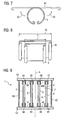
- FIG. 7 is the tubular bent mold shell wall 3 isolated, ie without connection to the filler neck part 6 according to the Figures 1 and 2 shown.
- the mold shell wall 3 is formed of such a resilient material that it is bent for insertion into the mold shell 2 of the mold 1 against a spring force - indicated by arrows 43 - and springs back without bending forces to a substantially flat plate, as with dashed lines 44th is indicated.
- the casting shell wall 3 can be stored particularly well on its own, because it does not remain in the bent state, but is present as a largely flat plate.
- the G demmantelverinrungsteil 36 may be formed as well as the mold shell wall 3 of such a resilient material, so that it is also on its own and without the action of bending forces as a largely flat plate.
- the casting shell wall 3 is shown in comparison to a further casting shell wall 45.
- the outer circumference of the casting chamber 7 determining edge length 21 is shorter than the corresponding edge length 46 of the casting shell wall 45.
- the mold shell wall 45 is otherwise identical to the mold shell wall 3 and therefore instead of the mold shell wall 3 with the filler neck part 6 of the mold 1 connectable, so that a not Mold shown in more detail with an enlarged outer circumference casting chamber 7 results.
- the casting shell wall 45 can also be designed in accordance with the casting shell wall 3 made of resilient material, see above that is also present as a largely flat plate when singling.
- FIG. 9 is the in FIG. 2 drawn section IX shown.
- the casting chamber 7 is closed at the end faces 49 and 49A of the casting mold 1 in each case with an end face 50 or 51.
- the end faces 50 and 51 are each formed by a flat plate 53 or 52 arranged on the end faces 49 and 49A of the casting mold 1.
- tie rods 62 and 63 For pressing the plates 52 and 53 against the mold shell wall 2 and the mold shell 5, these are braced against each other via tie rods 62 and 63, the sake of clarity in the Figures 1 and 2 not shown.
- seals 54 to 57 or 58 to 61 are provided on each of the closing end faces 50 and 51, which can be made, for example, of Perbunan.
- the seals 54, 57, 58 and 61 respectively encompass the mold shell 2 and are each formed with a U-shaped profile.
- Such cast resin seals 54 to 61 with U-shaped profile are usually available by the meter and thus inexpensive; In addition, they are particularly easy to attach to the mold shell wall 2 and the mold shell 5.
- By this embodiment of the seals 54, 58, 57 and 61 of the mold shell 2 is connected via the seals 54, 57, 58 and 61 with the final end faces 50 and 51, respectively.
Landscapes
- Engineering & Computer Science (AREA)
- Power Engineering (AREA)
- Mechanical Engineering (AREA)
- Manufacturing & Machinery (AREA)
- Casting Or Compression Moulding Of Plastics Or The Like (AREA)
- Moulds For Moulding Plastics Or The Like (AREA)
- Mold Materials And Core Materials (AREA)
Description
Die Erfindung betrifft eine Gießform für zylindrische Gießharzspulen, die sich entlang einer Achse erstreckt, mit einem äußeren, mit einer rohrförmig gebogenen Gießformmantelwand ausgebildeten Gießformmantel, der einen zylindrischen Gießraum umgibt und mit einem Einfüllspalt, über den der Gießraum mit Gießharz befüllbar ist, wobei der Gießformmantel mit einer lösbaren Verbindung in axialer Richtung auftrennbar ist.The invention relates to a casting mold for cylindrical cast resin coils, which extends along an axis, with an outer, formed with a tubular bent mold shell wall molding shell, which surrounds a cylindrical casting chamber and with a filling gap, through which the casting space can be filled with casting resin, wherein the casting shell can be separated with a detachable connection in the axial direction.
Eine solche Gießform ist aus der deutschen Patentschrift
Aufgabe der Erfindung ist es, eine Gießform der eingangs genannten Art anzugeben, die ein Gießen von Spulen mit verschiedenem Außenumfang mit vergleichsweise geringem Aufwand erlaubt.The object of the invention is to provide a mold of the type mentioned, which allows a casting of coils with different outer circumference with relatively little effort.
Die Aufgabe wird bei einer Gießform der eingangs genannten Art erfindungsgemäß dadurch gelöst, dass ein Gießformmantelverlängerungsteil vorgesehen ist, das derart ausgebildet ist, dass es an der aufgetrennten Verbindung zur Verlängerung des Gießformmantels in den Gießformmantel einsetzbar ist.The object is achieved in a casting mold of the type mentioned in the present invention, that a Gießformmantelverlängerungsteil is provided which is designed such that it can be used at the split connection for extending the mold shell in the mold shell.
Mit dem Gießformmantelverlängerungsteil kann der Gießformmantel verlängert und damit ein größerer Außenumfang eingestellt werden, so dass mit der erfindungsgemäßen Gießform Gießharzspulen mit zumindest zwei unterschiedlichen Außendurchmessern hergestellt werden können. Dadurch, dass der Gießformmantelverlängerungsteil in den Gießformmantel einsetzbar ausgebildet ist, kann das Gießformmantelverlängerungsteil mit sehr geringem Aufwand in den Gießformmantel eingesetzt und wieder entfernt werden. Insoweit sind hier nicht zwei vollständige Gießformen, sondern nur die erfindungsgemäße Gießform mit dem Gießformmantelverlängerungsteil erforderlich, um Spulen mit unterschiedlichem Außendurchmesser herstellen zu können. Ein geringer Aufwand ergibt sich insbesondere daraus, dass das Gießformverlängerungsteil sehr viel geringere Abmessungen aufweist, als eine vollständige Gießform.With the Gießformmantelverlängerungsteil the mold shell can be extended and thus set a larger outer circumference, so that casting molds can be produced with at least two different outer diameters with the mold according to the invention. Characterized in that the Gießformmantelverlängerungsteil is formed insertable into the mold shell, the Gießformmantelverlängerungsteil can be used with very little effort in the mold shell and removed again. In that regard, here are not two complete molds, but only the mold according to the invention with the Gießformmantelverlängerungsteil required to produce coils with different outer diameter can. A low cost arises in particular from the fact that the Gießformverlängerungsteil has much smaller dimensions than a complete mold.
Die Verbindung, mit der der Gießformmantel in axialer Richtung auftrennbar ist, kann beispielsweise eine Schraubverbindung sein. Vorzugsweise ist die Verbindung eine Hakverbindung. Dadurch kann der Gießformmantel durch einfaches Aufhaken der lösbaren Verbindung aufgetrennt und durch entsprechendes Einhaken wieder geschlossen werden. Ebenso leicht kann das entsprechend für die Hakverbindung ausgebildete Gießformmantelverlängerungsteil in den Gießformmantel eingesetzt werden, in dem es entsprechend eingehakt wird.The compound with which the casting shell can be separated in the axial direction can be, for example, a screw connection. Preferably, the compound is a hook connection. Thereby, the mold shell can be separated by simply hooking the releasable connection and closed by appropriate hooking again. Just as easily formed in accordance with the mold connection jacket extension part can be used in the mold shell in which it is hooked accordingly.
Bevorzugt ist die Gießformmantelwand an ihren die Verbindung bildenden, in axialer Richtung gerichteten Kanten jeweils derart korrespondierend zurückgebogen, dass die Kanten miteinander verhakbar sind. Die Hakverbindung kann somit besonders einfach durch Verhaken der Kanten miteinander gebildet werden.Preferably, the casting shell wall is in each case correspondingly bent back at its edges forming the connection, which are directed in the axial direction, such that the edges can be hooked to one another. The hook connection can thus be formed particularly easily by hooking the edges together.
Nach einer bevorzugten Ausgestaltung ist das Gießformmantelverlängerungsteil dünnwandig und aus einem derartig federnden Material ausgebildet, dass es zum Einsetzen in den Gießformmantel gegen eine Federkraft gebogen ist, die bei Vereinzelung des Gießformmantelverlängerungsteils dessen Zurückfedern zu einer weitgehend flachen Platte bewirkt. Dadurch liegt das Gießformmantelverlängerungsteil, wenn es nicht in den Gießformmantel eingesetzt ist, stets als weitgehend flache Platte vor, die besonders platzsparend und einfach lagerbar ist. Dies wirkt sich besonders vorteilhaft bei einer Vielzahl von Gießformmantelverlängerungsteilen mit unterschiedlichen Abmessungen aus, die zum Umrüsten der Gießform für eine Vielzahl von verschiedenen Außendurchmessern vorgesehen sind. Die mehreren Gießformmantelverlängerungsteile können dann leicht gelagert werden, da sie jeweils weitgehend flach sind und daher wenig Platz beanspruchen.According to a preferred embodiment, the Gießformmantelverlängerungsteil is thin-walled and formed of such a resilient material that it is bent for insertion into the mold shell against a spring force, which causes when singling the Gießformmantelverlängerungsteils its return springs to a substantially flat plate. As a result, the mold jacket extension part, if it is not used in the mold shell, always as a substantially flat plate before, which is particularly space-saving and easy to store. This has a particularly advantageous effect on a variety of Gießmantelweitängerungsteilen with different dimensions, which are provided for converting the mold for a variety of different outer diameters. The plurality Gießformmantelverlängerungsteile can then be easily stored, since they are each largely flat and therefore require little space.
Nach einer weiteren bevorzugten Ausgestaltung weist der Gießformmantel ein sich über die gesamte axiale Gießformlänge erstreckendes Gießformeinfüllstutzenteil mit dem Einfüllspalt auf, wobei das Gießformeinfüllstützenteil über die eine lösbare Verbindung und eine weitere lösbare Verbindung vollständig von der Gießformmantelwand abtrennbar ist. Vorteilhaft kann dadurch zusätzlich die gesamte Gießformmantelwand gegen eine andere, in ihrer die den Außenumfang des Gießraums bestimmende Länge zur einen Gießformmantelwand unterschiedliche weitere Gießformmantelwand anstelle der einen Gießformmantelwand mit dem Gießformeinfüllstutzenteil verbunden werden.According to a further preferred embodiment, the mold shell on a over the entire axial mold length extending Gießformeinfüllstutzenteil with the filling gap, wherein the Gießformeinfüllstützenteil is completely detachable from the mold shell wall via the one releasable connection and another releasable connection. Advantageously, in addition, the entire casting shell wall against another, in its the outer circumference of the casting room-determining length to a casting shell wall different further Gießformmantelwand instead of a casting shell wall are connected to the Gießformeinfüllstutzenteil.
Die Erfindung betrifft auch eine Gießform für zylindrische Gießharzspulen, die sich entlang einer Achse erstreckt, mit einem äußeren Gießformmantel, der einen zylindrischen Gießbereich umgibt und durch den der Außenumfang des Gießraums weitgehend definiert ist, wobei der Gießformmantel eine rohrförmig gebogene Gießformmantelwand und einem mit der Gießformmantelwand verbundenen, sich über die gesamte axiale Länge des Gießformmantels erstreckenden Gießharzeinfüllstutzenteil aufweist, über das der Gießraum mit Gießharz befüllbar ist, wobei der Gießformmantel mit einer lösbaren Verbindung in axialer Richtung auftrennbar ist.The invention also relates to a mold for cylindrical cast resin coils extending along an axis, comprising an outer mold shell surrounding a cylindrical casting region and substantially defining the outer periphery of the casting space, the casting shell having a tubular bent shell wall and a mold shell wall connected, over the entire axial length of the mold shell extending Gießharzeinfüllstutzenteil over which the casting chamber can be filled with resin, wherein the mold shell can be separated with a releasable connection in the axial direction.
Eine solche Gießform ist aus der schon eingangs genannten deutschen Patentschrift
Bei der bekannten Gießform ist - wie schon oben beschrieben - das Gießharzeinfüllstutzenteil mit der Gießformmantelwand fest verbunden.Such a mold is known from the already mentioned
In the known mold - as described above - the Gießharzeinfüllstutzenteil firmly connected to the mold shell wall.
Aufgabe der weiteren Erfindung ist es auch, eine Gießform der eingangs genannten Art anzugeben, die ein Gießen von Spulen mit verschiedenem Außenumfang mit vergleichsweise geringem Aufwand erlaubt.Object of the invention is also to provide a mold of the type mentioned, which allows a casting of coils with different outer circumference with relatively little effort.
Die Aufgabe wird bei einer Gießform der vorstehend genannten Art erfindungsgemäß auch dadurch gelöst, dass der Gießformmantel eine weitere lösbare Verbindung aufweist, mit der Gießformmantel in axialer Richtung auftrennbar ist und die Verbindungen derart angeordnet sind, dass der Gießharzeinfüllstutzenteil von der Gießformmantelwand abtrennbar ist, wobei die Verbindungen als Hakverbindung ausgebildet sind. Dadurch ist die Gießformmantelwand bei der erfindungsgemäßen Gießform leicht gegen eine andere Gießformmantelwand mit einer anderen Länge austauschbar, in dem die beiden Verbindungen gelöst, die eine Gießformmantelwand entfernt und an deren Stelle, die bis auf die den Außenumfang bestimmende Länge baugleiche andere Gießformmantelwand eingebaut werden. Insoweit kann die erfindungsgemäße Gießform leicht umgebaut werden, um eine Gießharzspule mit einem anderen Außendurchmesser herzustellen und es sind auch hier dafür nicht zwei vollständige Gießformen erforderlich, so dass sich auch hier ein geringerer Aufwand ergibt.The object is achieved in a casting mold of the aforementioned type according to the invention in that the mold shell has a further releasable connection with the mold shell is separable in the axial direction and the compounds are arranged such that the Gießharzeinfüllstutzenteil is separable from the mold shell wall, said Connections are designed as Hakverbindung. Thereby, the mold shell wall in the mold according to the invention is easily interchangeable with another mold shell wall with a different length, in which the two compounds are solved, which removes a Gießformmantelwand and in their place, which are built up to the outer circumference determining length identical other Gießformmantelwand. In that regard, the mold according to the invention can be easily converted to a cast resin coil with a different outer diameter produce and it is also here not two complete molds required, so that there is a lesser effort here.
Da die Verbindungen als Hakverbindungen ausgebildet sind, ergeben sich die schon oben angesprochenen Vorteile, nämlich dass die Verbindung schnell und leicht durch einfaches Aufhaken gelöst bzw. durch entsprechendes Einhaken wieder geschlossen werden kann. ,Since the compounds are designed as Hakverbindungen, the above-mentioned advantages, namely that the connection can be quickly and easily solved by simply hooking or closed by appropriate hooking arise. .
Bevorzugt weist das Gießharzeinfüllstutzenteil zumindest eine Teilmantelwand auf, die mit der Gießformmantelwand zur Bildung der zumindest einen Verbindung verhakbar ist, wobei die Gießformmantelwand an ihrer in axialer Richtung gerichteten, die zumindest eine Verbindung bildenden Kante zurückgebogen ist und Teilmantelwand an ihrer in axialer Richtung gerichteten die Verbindung bildenden Teilmantelwandkante entsprechend korrespondierend zu der die Verbindung bildenden Kante der Gießformmantelwand zurückgebogen ist. Dadurch sind sowohl die Gießformmantelwand als auch die Teilmantelwand besonders einfach miteinander verhakbar ausgebildet.Preferably, the Gießharzeinfüllstutzenteil has at least one part jacket wall, which is verhakbar with the Gießformmantelwand to form the at least one compound, wherein the Gießformmantelwand at its axially directed, the at least one compound forming edge is bent back and Teilmantelwand at its axially directed the connection forming part jacket wall edge corresponding to the connection forming edge of the casting shell wall is bent back. As a result, both the casting shell wall and the partial shell wall are particularly easy hooked together.
Vorzugsweise ist eine weitere Gießformmantelwand mit einer gegenüber der einen Gießformmantelwand unterschiedlichen, den Außenumfang des Gießraums definierenden Kantenlänge zum Austausch gegen die eine Gießformmantelwand vorgesehen. Insoweit kann durch einen einfachen Austausch der einen Gießformmantelwand gegen die weitere Gießformmantelwand mit geringem Aufwand eine andere Gießform gebildet werden, die gegenüber der mit der einen Gießformmantelwand gebildeten Gießform einen anderen Außenumfang des Gießraums aufweist.Preferably, a further casting shell wall is provided with an opposite to a casting shell wall, the outer periphery of the casting space defining edge length for replacement against a casting shell wall. In that regard, can be formed by a simple replacement of a casting shell wall against the other shell wall mold with little effort, another mold, which has a different outer circumference of the casting chamber with respect to the mold with a mold shell wall formed a different outer circumference.
Vorzugsweise ist die Gießformmantelwand aus einem derart federnden Material gebildet, dass die Gießformmantelwand zur Verbindung mit dem Gießharzeinfüllstutzenteil gegen eine Federkraft gebogen ist, die bei Vereinzelung der Gießformmantelwand deren Zurückfedern zu einer weitgehend flachen Platte bewirkt. Hierdurch ergeben sich die auch schon oben für das Gießformmantelverlängerungsteil angegebenen Vorteile, nämlich dass die Gießformmantelwand, sofern sie denn nicht gerade zur Bildung der Gießform verwendet wird, besonders gut lagerbar, da sie als eine weitgehend flache Platte vorliegt. Dies wirkt sich besonders vorteilhaft aus, wenn eine Vielzahl von Gießformmantelwänden mit verschiedenen den Außenumfang des Gießraums definierenden Kantenlängen zum gegenseitigen Austausch vorgesehen sind, und diese aus dem federnden Material ausgebildet sind, da sie dann alle einzeln jeweils als weitgehend flache Platte vorliegen und entsprechend leicht lagerbar sind.Preferably, the mold shell wall is formed of such a resilient material that the mold shell wall is bent for connection to the Gießharzeinfüllstutzenteil against a spring force, which causes the singling of the mold shell wall their spring back to a substantially flat plate. This results in the advantages already given above for the casting shell extension part, namely that the casting shell wall, insofar as it is not used for the formation of the casting mold, can be stored particularly well, since it is present as a substantially flat plate. This has a particularly advantageous if a plurality of Gießformmantelwänden with different the outer periphery of the casting space defining edge lengths are provided for mutual exchange, and they are formed from the resilient material, since they are then individually each as a largely flat plate and accordingly easy to store are.
Bei beiden erfindungsgemäßen Gießformen ist in einer jeweiligen Ausgestaltung das Gießformeinfüllstutzenteil vorteilhaft derart ausgebildet, dass die Breite des Einfüllspalts einstellbar ist. Dadurch ist vorteilhaft bei beiden erfindungsgemäßen Gießformen eine zusätzliche Möglichkeit gegeben, den Außenumfang des Gießraums durch Änderung der Breite des Einfüllspalts zu verändern. Insoweit kann hier durch ein geringfügiges Ändern der Breite des Einfüllspalts der Außenumfang des Gießraums besonders fein eingestellt werden.In the case of both casting molds according to the invention, in a particular embodiment, the mold filler neck part is advantageously designed such that the width of the filling gap is adjustable. As a result, it is advantageous in the case of both casting molds according to the invention to provide an additional possibility of changing the outer circumference of the casting space by changing the width of the filling gap. In that regard, the outer circumference of the casting space can be adjusted particularly fine here by slightly changing the width of the filling gap.
Das Gießharzeinfüllstutzenteil weist bevorzugt zwei sich nahezu über die gesamte axiale Gießformlänge erstreckende, winklig nach außen ragende Einfüllstutzenwände auf, die über den Einfüllspalt voneinander beabstandet sind und die über zumindest ein Distanzelement verbunden sind, durch dessen Elementbreite die Breite des Einfüllspalts festgelegt ist. Insoweit kann die Breite des Einfüllspalts besonders einfach durch den Austausch des Distanzelements gegen ein anderes Distanzelement mit einer anderen feststehenden Elementbreite eingestellt werden.The Gießharzeinfüllstutzenteil preferably has two almost over the entire axial mold length extending, angled outwardly projecting Einfüllstutzenwände, which are spaced apart from each other via the filling gap and which are connected via at least one spacer element, the width of the filling gap is determined by the element width. In that regard, the width of the filling gap can be particularly simple by replacing the spacer element with another Distance element can be set with a different fixed element width.
Nach einer bevorzugten Ausgestaltung ist die Elementbreite des Distanzelements einstellbar. Dadurch kann ohne einen Austausch des Distanzelements dessen Elementbreite und damit die Breite des Einfüllspalts eingestellt werden.According to a preferred embodiment, the element width of the spacer element is adjustable. As a result, without an exchange of the spacer element whose element width and thus the width of the filling gap can be adjusted.
Bei beiden erfindungsgemäßen Gießformen ist vorzugsweise vorgesehen, dass der Gießformmantel zumindest an einer Gießformstirnseite auf einer den Gießraum gießformstirnseitig abschließenden Stirnfläche steht. Diese Ausgestaltung bietet den Vorteil, dass der Gießraum stirnseitig mit der gleichen Stirnfläche besonders leicht auch für verschiedene über den Gießformmantel eingestellte Außendurchmesser des Gießraums abgeschlossen werden kann.In the case of both casting molds according to the invention, provision is preferably made for the casting shell to rest on an end surface of the casting mold front side at least on a casting face end face. This embodiment has the advantage that the pouring space can be completed particularly easily for the front face with the same end face also for different outer diameter of the pouring space set over the casting mold shell.
Weiter bevorzugt ist der Gießraum an der abschließenden Stirnfläche mit einer Dichtung abgedichtet. Hierdurch ist vorteilhaft ein Austreten von Gießharz beim Befüllen der Gießform an der abschließenden Stirnfläche vermieden.More preferably, the casting chamber is sealed at the closing end face with a seal. As a result, leakage of cast resin during filling of the casting mold at the closing end face is advantageously avoided.
Bevorzugt umgreift die Dichtung den Gießformmantel. Dazu kann die Dichtung beispielsweise als U-Profil ausgebildet sein, dass stirnseitig über die Gießformmantelwand und die entsprechenden Wände des Gießformeinfüllstutzenteils übergestülpt sind, wobei dann der Gießformmantel über die Dichtung an der abschließenden Stirnfläche anliegt. Eine solche Dichtung ist als Massenware und daher sehr preisgünstig erhältlich.Preferably, the seal surrounds the mold shell. For this purpose, the seal may be formed, for example, as a U-profile that the front side are slipped over the Gießformmantelwand and the corresponding walls of the Gießformeinfüllstutzenteils, in which case the mold jacket rests on the seal on the final face. Such a seal is available as a commodity and therefore very inexpensive.
Vorzugsweise ist jede Verbindung mit einer Dichtung abgedichtet. Dadurch ist es beim Gießen der Gießharzspule vermieden, dass Gießharz durch die Verbindung nach außen austritt und die Verbindung durch das Gießharz verklebt wird. Zur Abdichtung kann beispielsweise eine entsprechende Dichtmasse oder eine Gummidichtung oder ein entsprechender Dichtungsschaum vorgesehen sein.Preferably, each connection is sealed with a gasket. Thereby, it is avoided during casting of the cast resin coil that casting resin exits through the connection to the outside and the connection is bonded by the casting resin. For sealing, for example, a corresponding sealing compound or a rubber seal or a corresponding sealing foam may be provided.
Nach einer bevorzugten Ausgestaltung weist der Gießformmantel einen Überlappungswandteil auf, der die eine Verbindung innenseitig in Umfangsrichtung überlappt. Dadurch ist eine zusätzliche Abdichtung der Verbindung gegen das Gießharz erreicht, da nach dem Einsetzen der Gießharzspule in die Gießform der Überlappungswandteil von innen gegen die Verbindung gepresst wird, wodurch diese für das Gießharz schwer zugänglich ist.According to a preferred embodiment, the casting shell has an overlap wall part which overlaps the one connection on the inside in the circumferential direction. As a result, an additional sealing of the connection is achieved against the casting resin, since after insertion of the cast resin coil in the mold of the overlapping wall portion is pressed from the inside against the connection, whereby this is difficult to access for the casting resin.
Die Erfindung wird anhand der Zeichnung näher erläutert. Es zeigen:
Figur 1- eine perspektivische Ansicht eines Gießformmantels,
Figur 2- eine Draufsicht auf den Gießformmantel gemäß
Figur 1 Figur 3- einen vergrößerten Ausschnitt auf die Draufsicht gemäß
Figur 2 Figur 4- eine Draufsicht auf eine modifizierte Gießform,
Figur 5- eine perspektivische Ansicht eines Gießformverlängerungsteils,
Figur 6- eine Draufsicht auf die
Gießform gemäß Figur 4 mit eingesetztem Gießformverlängerungsteil gemäßFigur 5 , Figur 7- eine Gießformmantelwand,
Figur 8- eine und eine weitere Gießformmantelwand im Vergleich, und
Figur 9- eine Schnittansicht gemäß
Figur 2
- FIG. 1
- a perspective view of a mold shell,
- FIG. 2
- a plan view of the mold shell according to
FIG. 1 . - FIG. 3
- an enlarged section of the plan view according
FIG. 2 - FIG. 4
- a top view of a modified mold,
- FIG. 5
- a perspective view of a Gießformverlängerungsteils,
- FIG. 6
- a plan view of the mold according to
FIG. 4 with inserted mold extension part according toFIG. 5 . - FIG. 7
- a casting shell wall,
- FIG. 8
- one and another casting shell wall in comparison, and
- FIG. 9
- a sectional view according to
FIG. 2 ,
In
Der Gießformmantel 2 weist einen Einfüllspalt 9 auf, über den der Gießbereich 7 mit einem Gießharz befüllbar ist. Der Gießformmantel 2 weist vorliegend eine erste schematisch mit einem Strich angedeutete Verbindung 10 auf, über die der Gießformmantel 2 lösbar in axialer Richtung auftrennbar ist. Der Gießformmantel 2 weist eine zweite, ebenfalls schematisch mit einer Linie angedeutete lösbare Verbindung 11 auf, die ebenfalls dem axialen Auftrennen des Gießformmantels 2 dient. Die Ausführung der beiden lösbaren Verbindungen 10 und 11 ist in der Beschreibung zu den
Der Gießformeinfüllstutzenteil 6 weist eine erste und eine zweite Teilmantelwand 12 bzw. 13 auf, über die er jeweils mit der Gießformmantelwand 3 an den lösbaren Verbindungen 10 und 11 verbunden ist. Der Gießformeinfüllstutzenteil 6 weist weiterhin zwei sich über die gesamte axiale Gießformlänge erstreckende und winklig nach außen ragende Einfüllstutzenwände 14 bzw. 15 auf, die mit den Teilmantelwänden 12 bzw. 13 verbunden sind. Die Einfüllstutzenwände 14 und 15 sind über den Einfüllspalt 9 voneinander beabstandet und über Distanzelemente 16, 17 und 18 verbunden. Die Distanzelemente 16 bis 18 weisen alle eine gleiche Elementbreite 19 auf (siehe
Die Distanzelemente 16 bis 18 können mit fester Elementbreite 19 ausgebildet sein. Vorliegend kann jedoch die Elementbreite 19 der Distanzelemente 16 bis 19 variiert werden, wie weiter unten erläutert wird (siehe
The
Über die lösbaren Verbindungen 10 und 11 kann der Gießformeinfüllstutzenteil 6 vollständig von der Gießformmantelwand 3 abgetrennt werden. Dadurch kann die eine Gießformmantelwand 3 durch eine baugleiche, sich aber in ihrer den Außenumfang des Gießraums 7 definierenden Kantenlänge 21 (siehe
In
Bei der in
Zur Abdeckung der lösbaren Verbindung 10 und um den Verlauf des Gießraums 7 an seinem Außenumfang zu vergleichmäßigen, sowie um die lösbare Verbindung 10 noch besser gießharzdicht auszuführen, kann der Gießformmantel 2 eine mit gestrichelten Linien angedeutete Überlappungswand 25 aufweisen, die die Verbindung 10 innenseitig in Umfangsrichtung überlappt. Vorliegend ist die Überlappungswand mit der Teilmantelwand 12 des Einfüllstutzenteils 6 verbunden, sie kann ebenso statt dessen mit der Gießformmantelwand 3 verbunden sein.To cover the
Die Breite 16 des Einfüllspalts 9 ist über die Elementbreiten der Distanzelemente, von denen in
In
In
Die Gießform 26 kann auch zusätzlich mit einer der lösbaren Verbindung 11 gemäß
Die Gießformmantelwand 27 bzw. das Gießformmantelverlängerungsteil 36 können ebenso zur innenseitigen Überlappung der Verbindungen 39 und 38 der Überlappungswand 25 entsprechende Überlappungswände aufweisen.The casting
In
In
In
Zum Abdichten des Gießraums 7 sind an jeder der abschließenden Stirnflächen 50 und 51 Dichtungen 54 bis 57 bzw. 58 bis 61 vorgesehen, die beispielsweise aus Perbunan ausgebildet sein können. Die Dichtungen 54, 57, 58 und 61 umgreifen dabei jeweils den Gießformmantel 2 und sind dazu jeweils mit U-förmigem Profil ausgebildet. Solche Gießharzdichtungen 54 bis 61 mit U-förmigem Profil sind in der Regel als Meterware erhältlich und dadurch preiswert; darüber hinaus sind sie besonders leicht an der Gießformmantelwand 2 bzw. dem Gießformmantel 5 anbringbar. Durch diese Ausführung der Dichtungen 54, 58, 57 und 61 ist der Gießformmantel 2 über die Dichtungen 54, 57, 58 und 61 mit den abschließenden Stirnflächen 50 bzw. 51 verbunden. For sealing the pouring
Claims (17)
- Casting mold (1, 26) for cylindrical cast-resin coils, which extends along an axis (4), with an outer casting-mold casing (2, 28) which is designed with a tubularly bent casting-mold casing wall (3, 27) and which surrounds a cylindrical casting space (7, 37), and with a filling gap (9), via which the casting space (7, 37) can be filled with casting resin, the casting-mold casing (2, 28) being severable in the axial direction by means of a releasable connection (10, 29), characterized in that a casting-mold casing lengthening part (36) is provided, which is designed in such a way that it can be inserted into the casting-mold casing (2, 28) at the severed connection (10) in order to lengthen the casting-mold casing (2, 28).
- Casting mold according to claim 1, characterized in that the connection (10, 29) is a hook connection.
- Casting mold according to claim 2, characterized in that the casting-mold casing wall (27) is correspondingly bent back, at its axial directed edges forming the connection (10), in each case in such a way that the edges can be hooked together with one another.
- Casting mold according to one of the preceding claims, characterized in that the casting-mold casing lengthening part (36) is produced so as to be thin-walled and formed from such a resilient material that, for insertion into the casting-mold casing (2, 28), it is bent counter to a spring force (43) which, when the casting-mold casing lengthening part (36) is separated, causes the latter to spring back into a largely flat plate.
- Casting mold according to one of the preceding claims, characterized in that the casting-mold casing (2, 28) has a casting-mold filling connection part (6, 30) extending over the entire axial casting-mold length and having the filling gap (9), the casting-mold filling connection part (6, 30) being separable completely from the casting-mold casing wall (3, 27) via the one releasable connection (10, 29) and a further releasable connection (11).
- Casting mold for cylindrical cast-resin coils, which extends along an axis (4), with an outer casting-mold casing (2) which surrounds a cylindrical casting region (7) and by which the outer circumference of the casting space (7) is largely defined, the casting-mold casing (2) having a tubularly bent casting-mold casing wall (3) and a casting-resin filling connection part (6) which is connected to the casting-mold casing wall (3) and extends over the entire axial length of the casting-mold casing (2) and via which the casting space (7) can be filled with casting resin, the casting-mold casing (2) being severable in the axial direction by means of a releasable connection (10), characterized in that the casting-mold casing (2) has a further releasable connection (11), by means of which the casting-mold casing (2) is severable in the axial direction, and the connections (10, 11) are arranged in such a way that the casting-resin filling connection part (6) can be separated from the casting-mold casing wall (3), the connections (10, 11) being designed as a hook connection.
- Casting mold according to claim 6, characterized in that the casting-resin filling connection part (6) has at least one part-casing wall (12) which can be hooked together with the casting-mold casing wall (3) to form the at least one connection (10), the casting-mold casing wall (3) being bent back in the region of its axially directed edge (22) forming the at least one connection (10), and the part-casing wall (12) being bent back in the region of its axially directed part-casing wall edge (23) forming the connection (10), correspondingly to that edge (22) of the casting-mold casing wall (3) which forms the connection (10).
- Casting mold according to either one of claims 6 and 7, characterized in that a further casting-mold casing wall (45), with an edge length different from that of the one casting-mold casing wall (3) and defining the outer circumference of the casting space (7), is provided for the purpose of exchange for the one casting-mold casing wall (3).
- Casting mold according to one of claims 6 to 8, characterized in that the casting-mold casing wall (3) is formed from such a resilient material that, for the connection to the casting-resin filling connection part (6), the casting-mold casing wall (3) is bent counter to the spring force which, when the casting-mold casing wall (3) is separated, causes the latter to spring back into a largely flat plate.
- Casting mold according to one of claims 5 to 8, characterized in that the casting-mold filling connection part (6) is designed in such a way that the width (20) of the filling gap (9) is adjustable.
- Casting mold according to claim 10, characterized in that the casting-resin filling connection part (6) has two filling connection walls (14, 15) which extend over the entire axial casting-mold length and project angularly outwards and which are spaced apart from one another via the filling gap (9) and are connected via at least one spacer element (16, 17, 18), by the element width (19) of which the width (20) of the filling gap (9) is fixed.
- Casting mold according to claim 11, characterized in that the element width (19) of the spacer element (16, 17, 18) is adjustable.
- Casting mold according to one of the preceding claims, characterized in that the casting-mold casing (5) stands, at least on one casting-mold fore-side (49, 49A), on an end face (50, 51) closing off the casting space on the fore-side.
- Casting mold according to claim 13, characterized in that the casting space (7) is sealed off at the closing-off end face (50, 51) by means of a cast-resin seal (54, 55, 56, 57, 58, 59, 60, 61).
- Casting mold according to claim 14, characterized in that the cast-resin seal (54, 55, 56, 57, 58, 59, 60, 61) surrounds the casting-mold casing (2).
- Casting mold according to one of claims 6 to 15, characterized in that each connection (10, 11) is sealed off by means of a cast-resin seal (24).
- Casting mold according to one of the preceding claims, characterized in that the casting-mold casing (2) has an overlapping wall part (25) which overlaps the one connection (10) on the inside in the circumferential direction.
Applications Claiming Priority (5)
| Application Number | Priority Date | Filing Date | Title |
|---|---|---|---|
| DE10246539 | 2002-09-30 | ||
| DE10246539 | 2002-09-30 | ||
| DE10248782 | 2002-10-15 | ||
| DE10248782A DE10248782B4 (en) | 2002-09-30 | 2002-10-15 | Casting mold for cylindrical cast resin coils |
| PCT/DE2003/003139 WO2004030887A1 (en) | 2002-09-30 | 2003-09-17 | Casting mould for cylindrical cast resin coils |
Publications (2)
| Publication Number | Publication Date |
|---|---|
| EP1549474A1 EP1549474A1 (en) | 2005-07-06 |
| EP1549474B1 true EP1549474B1 (en) | 2008-11-05 |
Family
ID=32070714
Family Applications (1)
| Application Number | Title | Priority Date | Filing Date |
|---|---|---|---|
| EP03757679A Expired - Fee Related EP1549474B1 (en) | 2002-09-30 | 2003-09-17 | Casting mould for cylindrical cast resin coils |
Country Status (5)
| Country | Link |
|---|---|
| EP (1) | EP1549474B1 (en) |
| AU (1) | AU2003273743A1 (en) |
| DE (2) | DE10248782B4 (en) |
| ES (1) | ES2312807T3 (en) |
| WO (1) | WO2004030887A1 (en) |
Families Citing this family (1)
| Publication number | Priority date | Publication date | Assignee | Title |
|---|---|---|---|---|
| US20060054758A1 (en) | 2004-09-16 | 2006-03-16 | Simpson Allen H | Fixture for holding a preform during a heating process |
Family Cites Families (4)
| Publication number | Priority date | Publication date | Assignee | Title |
|---|---|---|---|---|
| DE3430586A1 (en) * | 1984-08-20 | 1986-02-27 | Transformatoren Union Ag, 7000 Stuttgart | METHOD FOR PRODUCING WINDINGS EMBEDDED IN CASTING RESIN FOR TRANSFORMERS |
| JPH0322512A (en) * | 1989-06-20 | 1991-01-30 | Matsushita Electric Ind Co Ltd | Manufacture of spacer for resin-molded coil, device therefor and manufacture of resin-molded coil |
| DE4426138C2 (en) * | 1994-07-22 | 1998-04-23 | Siemens Ag | Casting mold for a transformer coil with the possibility of checking the potting |
| JP3374643B2 (en) * | 1996-03-27 | 2003-02-10 | 株式会社日立製作所 | Resin mold coil |
-
2002
- 2002-10-15 DE DE10248782A patent/DE10248782B4/en not_active Expired - Fee Related
-
2003
- 2003-09-17 WO PCT/DE2003/003139 patent/WO2004030887A1/en not_active Application Discontinuation
- 2003-09-17 AU AU2003273743A patent/AU2003273743A1/en not_active Abandoned
- 2003-09-17 DE DE50310753T patent/DE50310753D1/de not_active Expired - Lifetime
- 2003-09-17 ES ES03757679T patent/ES2312807T3/en not_active Expired - Lifetime
- 2003-09-17 EP EP03757679A patent/EP1549474B1/en not_active Expired - Fee Related
Also Published As
| Publication number | Publication date |
|---|---|
| AU2003273743A1 (en) | 2004-04-23 |
| DE10248782B4 (en) | 2005-08-04 |
| DE50310753D1 (en) | 2008-12-18 |
| EP1549474A1 (en) | 2005-07-06 |
| ES2312807T3 (en) | 2009-03-01 |
| WO2004030887A1 (en) | 2004-04-15 |
| DE10248782A1 (en) | 2004-04-15 |
Similar Documents
| Publication | Publication Date | Title |
|---|---|---|
| DE2604477A1 (en) | METHOD AND DEVICE FOR ENCAPSULATING CABLES | |
| EP0103237A2 (en) | Method of making resin-encapsulated coils for transformers | |
| DE102013213688A1 (en) | Casting method for producing a protective casing around a surge arrester and a mold for this purpose | |
| DE60016796T2 (en) | METHOD FOR PRODUCING PLASTIC ROTORS | |
| EP2242628B1 (en) | Method for the production of concrete pipes | |
| EP1549474B1 (en) | Casting mould for cylindrical cast resin coils | |
| DE2802551C2 (en) | Device for ring-shaped corrugation of the wall of smooth tubes | |
| DE19912917A1 (en) | Electrical noise absorber and method for mounting it on a cable | |
| EP3000571A1 (en) | Device for manufacturing concrete moulds | |
| DE2206104A1 (en) | Concrete piles cast-in-place and methods of making them | |
| DE102010048053A1 (en) | Mold for manufacturing hollow concrete structure e.g. container of three-chamber purification system, has inner casing which comprises segments that are connected with rubber strips | |
| EP1549473B1 (en) | Casting mould for cylindrical cast resin coils | |
| DE69632260T2 (en) | COLLAPSE CORE | |
| DE10255564B4 (en) | Casting mold for cylindrical cast resin coils | |
| EP1835091A2 (en) | Spacer tube for tying rods | |
| EP3702653A1 (en) | Feed-through for a floor or ceiling element | |
| DE3031687A1 (en) | DEVICE FOR PROTECTING THE END AREAS OF PIPES AGAINST MECHANICAL DAMAGE | |
| DE3943214A1 (en) | METHOD FOR PRODUCING SUPPORT POST AND SUPPORT POST PRODUCED BY THE PROCESS | |
| DE102009038647A1 (en) | Apparatus and method for casting a component | |
| DE102020204416A1 (en) | Molding core for a mold for the production of hollow concrete bodies and a molding device having such a molding core | |
| DE102020204417A1 (en) | Molding core for a mold for the production of hollow concrete bodies and a molding device having such a molding core | |
| DE10042143B4 (en) | Device for passing media lines through a wall | |
| DE1926788U (en) | ELECTRIC CAPACITOR, IN PARTICULAR WITH A CYLINDER-SHAPED METAL HOUSING. | |
| EP4151322A1 (en) | Coaxial cartridge with integrated reinforcement for pressure-free extrusion of a flowable multi-component mass | |
| DE7433174U (en) | Electric motor |
Legal Events
| Date | Code | Title | Description |
|---|---|---|---|
| PUAI | Public reference made under article 153(3) epc to a published international application that has entered the european phase |
Free format text: ORIGINAL CODE: 0009012 |
|
| 17P | Request for examination filed |
Effective date: 20050131 |
|
| AK | Designated contracting states |
Kind code of ref document: A1 Designated state(s): AT BE BG CH CY CZ DE DK EE ES FI FR GB GR HU IE IT LI LU MC NL PT RO SE SI SK TR |
|
| AX | Request for extension of the european patent |
Extension state: AL LT LV MK |
|
| DAX | Request for extension of the european patent (deleted) | ||
| RBV | Designated contracting states (corrected) |
Designated state(s): DE ES FR IT |
|
| 17Q | First examination report despatched |
Effective date: 20050725 |
|
| GRAP | Despatch of communication of intention to grant a patent |
Free format text: ORIGINAL CODE: EPIDOSNIGR1 |
|
| GRAS | Grant fee paid |
Free format text: ORIGINAL CODE: EPIDOSNIGR3 |
|
| GRAA | (expected) grant |
Free format text: ORIGINAL CODE: 0009210 |
|
| AK | Designated contracting states |
Kind code of ref document: B1 Designated state(s): DE ES FR IT |
|
| REF | Corresponds to: |
Ref document number: 50310753 Country of ref document: DE Date of ref document: 20081218 Kind code of ref document: P |
|
| REG | Reference to a national code |
Ref country code: ES Ref legal event code: FG2A Ref document number: 2312807 Country of ref document: ES Kind code of ref document: T3 |
|
| PLBE | No opposition filed within time limit |
Free format text: ORIGINAL CODE: 0009261 |
|
| STAA | Information on the status of an ep patent application or granted ep patent |
Free format text: STATUS: NO OPPOSITION FILED WITHIN TIME LIMIT |
|
| 26N | No opposition filed |
Effective date: 20090806 |
|
| REG | Reference to a national code |
Ref country code: FR Ref legal event code: PLFP Year of fee payment: 14 |
|
| REG | Reference to a national code |
Ref country code: FR Ref legal event code: PLFP Year of fee payment: 15 |
|
| REG | Reference to a national code |
Ref country code: FR Ref legal event code: PLFP Year of fee payment: 16 |
|
| PGFP | Annual fee paid to national office [announced via postgrant information from national office to epo] |
Ref country code: FR Payment date: 20200921 Year of fee payment: 18 |
|
| REG | Reference to a national code |
Ref country code: DE Ref legal event code: R081 Ref document number: 50310753 Country of ref document: DE Owner name: SIEMENS ENERGY GLOBAL GMBH & CO. KG, DE Free format text: FORMER OWNER: SIEMENS AKTIENGESELLSCHAFT, 80333 MUENCHEN, DE |
|
| PGFP | Annual fee paid to national office [announced via postgrant information from national office to epo] |
Ref country code: DE Payment date: 20201118 Year of fee payment: 18 Ref country code: IT Payment date: 20200924 Year of fee payment: 18 Ref country code: ES Payment date: 20201217 Year of fee payment: 18 |
|
| REG | Reference to a national code |
Ref country code: DE Ref legal event code: R119 Ref document number: 50310753 Country of ref document: DE |
|
| PG25 | Lapsed in a contracting state [announced via postgrant information from national office to epo] |
Ref country code: FR Free format text: LAPSE BECAUSE OF NON-PAYMENT OF DUE FEES Effective date: 20210930 Ref country code: DE Free format text: LAPSE BECAUSE OF NON-PAYMENT OF DUE FEES Effective date: 20220401 |
|
| REG | Reference to a national code |
Ref country code: ES Ref legal event code: FD2A Effective date: 20221028 |
|
| PG25 | Lapsed in a contracting state [announced via postgrant information from national office to epo] |
Ref country code: IT Free format text: LAPSE BECAUSE OF NON-PAYMENT OF DUE FEES Effective date: 20210917 |
|
| PG25 | Lapsed in a contracting state [announced via postgrant information from national office to epo] |
Ref country code: ES Free format text: LAPSE BECAUSE OF NON-PAYMENT OF DUE FEES Effective date: 20210918 |