EP1549245B1 - Device for the surgical treatment of female prolapse - Google Patents
Device for the surgical treatment of female prolapse Download PDFInfo
- Publication number
- EP1549245B1 EP1549245B1 EP03766391A EP03766391A EP1549245B1 EP 1549245 B1 EP1549245 B1 EP 1549245B1 EP 03766391 A EP03766391 A EP 03766391A EP 03766391 A EP03766391 A EP 03766391A EP 1549245 B1 EP1549245 B1 EP 1549245B1
- Authority
- EP
- European Patent Office
- Prior art keywords
- length
- arms
- distance
- patients
- front portion
- Prior art date
- Legal status (The legal status is an assumption and is not a legal conclusion. Google has not performed a legal analysis and makes no representation as to the accuracy of the status listed.)
- Expired - Lifetime
Links
- 208000012287 Prolapse Diseases 0.000 title abstract description 23
- 238000001356 surgical procedure Methods 0.000 title abstract description 12
- 210000000056 organ Anatomy 0.000 claims abstract description 14
- 239000000463 material Substances 0.000 claims description 18
- 241000826860 Trapezium Species 0.000 claims description 8
- 239000004743 Polypropylene Substances 0.000 claims description 5
- -1 polypropylene Polymers 0.000 claims description 5
- 229920001155 polypropylene Polymers 0.000 claims description 5
- 241000283690 Bos taurus Species 0.000 claims description 4
- 210000004379 membrane Anatomy 0.000 claims description 4
- 239000012528 membrane Substances 0.000 claims description 4
- 210000003516 pericardium Anatomy 0.000 claims description 4
- 210000004876 tela submucosa Anatomy 0.000 claims description 4
- 102000008186 Collagen Human genes 0.000 claims description 3
- 108010035532 Collagen Proteins 0.000 claims description 3
- 229920001436 collagen Polymers 0.000 claims description 3
- 210000000813 small intestine Anatomy 0.000 claims description 3
- SXRSQZLOMIGNAQ-UHFFFAOYSA-N Glutaraldehyde Chemical compound O=CCCCC=O SXRSQZLOMIGNAQ-UHFFFAOYSA-N 0.000 claims description 2
- HTTJABKRGRZYRN-UHFFFAOYSA-N Heparin Chemical compound OC1C(NC(=O)C)C(O)OC(COS(O)(=O)=O)C1OC1C(OS(O)(=O)=O)C(O)C(OC2C(C(OS(O)(=O)=O)C(OC3C(C(O)C(O)C(O3)C(O)=O)OS(O)(=O)=O)C(CO)O2)NS(O)(=O)=O)C(C(O)=O)O1 HTTJABKRGRZYRN-UHFFFAOYSA-N 0.000 claims description 2
- 210000000109 fascia lata Anatomy 0.000 claims description 2
- 229960002897 heparin Drugs 0.000 claims description 2
- 229920000669 heparin Polymers 0.000 claims description 2
- 239000011159 matrix material Substances 0.000 claims description 2
- 239000000203 mixture Substances 0.000 claims description 2
- 230000036961 partial effect Effects 0.000 abstract description 6
- 238000011282 treatment Methods 0.000 abstract description 4
- 210000004291 uterus Anatomy 0.000 description 19
- 210000003932 urinary bladder Anatomy 0.000 description 8
- 210000001215 vagina Anatomy 0.000 description 5
- 239000007943 implant Substances 0.000 description 4
- 210000003205 muscle Anatomy 0.000 description 4
- 210000000664 rectum Anatomy 0.000 description 4
- 206010011803 Cystocele Diseases 0.000 description 3
- 201000004989 Enterocele Diseases 0.000 description 3
- 206010019909 Hernia Diseases 0.000 description 3
- 206010046543 Urinary incontinence Diseases 0.000 description 3
- 238000013459 approach Methods 0.000 description 3
- 210000000936 intestine Anatomy 0.000 description 3
- 230000002829 reductive effect Effects 0.000 description 3
- 206010002091 Anaesthesia Diseases 0.000 description 2
- 208000034657 Convalescence Diseases 0.000 description 2
- 206010064700 Hysterocele Diseases 0.000 description 2
- 238000001949 anaesthesia Methods 0.000 description 2
- 230000037005 anaesthesia Effects 0.000 description 2
- 210000003041 ligament Anatomy 0.000 description 2
- 238000000034 method Methods 0.000 description 2
- 210000001835 viscera Anatomy 0.000 description 2
- 208000034347 Faecal incontinence Diseases 0.000 description 1
- 208000005422 Foreign-Body reaction Diseases 0.000 description 1
- 206010021639 Incontinence Diseases 0.000 description 1
- 241001465754 Metazoa Species 0.000 description 1
- 206010038084 Rectocele Diseases 0.000 description 1
- 230000003187 abdominal effect Effects 0.000 description 1
- 210000003679 cervix uteri Anatomy 0.000 description 1
- 239000013065 commercial product Substances 0.000 description 1
- 210000002808 connective tissue Anatomy 0.000 description 1
- 238000003745 diagnosis Methods 0.000 description 1
- 238000006073 displacement reaction Methods 0.000 description 1
- 238000002224 dissection Methods 0.000 description 1
- 230000003628 erosive effect Effects 0.000 description 1
- 210000000416 exudates and transudate Anatomy 0.000 description 1
- 230000002650 habitual effect Effects 0.000 description 1
- 238000009802 hysterectomy Methods 0.000 description 1
- 230000000670 limiting effect Effects 0.000 description 1
- 239000007788 liquid Substances 0.000 description 1
- 230000007170 pathology Effects 0.000 description 1
- 210000004197 pelvis Anatomy 0.000 description 1
- 230000000149 penetrating effect Effects 0.000 description 1
- 230000000144 pharmacologic effect Effects 0.000 description 1
- 230000000284 resting effect Effects 0.000 description 1
- 239000000725 suspension Substances 0.000 description 1
- 229920002994 synthetic fiber Polymers 0.000 description 1
- 210000001519 tissue Anatomy 0.000 description 1
- 210000003708 urethra Anatomy 0.000 description 1
- 230000002485 urinary effect Effects 0.000 description 1
Images

Classifications
-
- A—HUMAN NECESSITIES
- A61—MEDICAL OR VETERINARY SCIENCE; HYGIENE
- A61F—FILTERS IMPLANTABLE INTO BLOOD VESSELS; PROSTHESES; DEVICES PROVIDING PATENCY TO, OR PREVENTING COLLAPSING OF, TUBULAR STRUCTURES OF THE BODY, e.g. STENTS; ORTHOPAEDIC, NURSING OR CONTRACEPTIVE DEVICES; FOMENTATION; TREATMENT OR PROTECTION OF EYES OR EARS; BANDAGES, DRESSINGS OR ABSORBENT PADS; FIRST-AID KITS
- A61F2/00—Filters implantable into blood vessels; Prostheses, i.e. artificial substitutes or replacements for parts of the body; Appliances for connecting them with the body; Devices providing patency to, or preventing collapsing of, tubular structures of the body, e.g. stents
- A61F2/0004—Closure means for urethra or rectum, i.e. anti-incontinence devices or support slings against pelvic prolapse
- A61F2/0031—Closure means for urethra or rectum, i.e. anti-incontinence devices or support slings against pelvic prolapse for constricting the lumen; Support slings for the urethra
- A61F2/0036—Closure means for urethra or rectum, i.e. anti-incontinence devices or support slings against pelvic prolapse for constricting the lumen; Support slings for the urethra implantable
- A61F2/0045—Support slings
-
- A—HUMAN NECESSITIES
- A61—MEDICAL OR VETERINARY SCIENCE; HYGIENE
- A61F—FILTERS IMPLANTABLE INTO BLOOD VESSELS; PROSTHESES; DEVICES PROVIDING PATENCY TO, OR PREVENTING COLLAPSING OF, TUBULAR STRUCTURES OF THE BODY, e.g. STENTS; ORTHOPAEDIC, NURSING OR CONTRACEPTIVE DEVICES; FOMENTATION; TREATMENT OR PROTECTION OF EYES OR EARS; BANDAGES, DRESSINGS OR ABSORBENT PADS; FIRST-AID KITS
- A61F2/00—Filters implantable into blood vessels; Prostheses, i.e. artificial substitutes or replacements for parts of the body; Appliances for connecting them with the body; Devices providing patency to, or preventing collapsing of, tubular structures of the body, e.g. stents
- A61F2/0063—Implantable repair or support meshes, e.g. hernia meshes
Definitions
- the present invention concerns a device for supporting the female pelvic organs, to be surgically implanted in uro-gynaecological treatments.
- female prolapse means the sinking or displacement through the vagina of a female pelvic organ, bladder, uterus or rectum, which may occur for only one of these organs or for more than one organ simultaneously.
- total prolapse When all the pelvic organs - bladder, uterus and rectum - are involved, the term used is "total prolapse" and in this case the whole vagina is affected by the sinking of the internal organs, to the extent that there is often a real evagination of the vagina.
- Prolapse is a fairly frequent problem in women and may occur following a difficult vaginal birth or problems of the connective tissues.
- prolapse often appears in association with other disturbances, such as urinary or faecal incontinence.
- other disturbances such as urinary or faecal incontinence.
- female prolapse can therefore have important affects on the quality of life and may cause severe limitations in daily living.
- a further disadvantage is that surgical operations of this type require total anaesthesia of the patient, who will also require relatively long periods of hospitalisation and convalescence.
- the European Patent Application EP-A- 774 240 discloses an implant for suspension of the urinary bladder in cases of incontinence of urine in women having a flat flexible structure in which four projections start from a triangle-like oval base. Two of these four projections run on opposite sides of the longitudinal axis of the base and the two other projections run generally in the opposite direction to the first two projections on opposite sides of the longitudinal axis of the base.
- the Applicant has now found a reticular or laminar device according to claim 1 which, when surgically implanted, provides support for the female pelvic organs in the case of prolapse of the vaginal vault or partial or total prolapse through the vagina.
- the device according to the invention may in fact be vaginally, mixed vaginally/abdominally or vaginally/laparoscopically implanted, or implanted by means of mini-invasive surgery, requiring in the majority of cases only local anaesthesia, the hospitalisation and convalescence times are considerably reduced and no organ is removed.
- a flat implantable device made of material with a reticular or laminar structure for supporting the female pelvic organs, characterised in that it has a central body with a trapezoid shape having four arms, in which may be distinguished:
- the present device may also be realised as in Figure 2a, with the longitudinal cleft H which cuts the rear portion D of the central body in two halves; this device adapts to a type of surgical implant in which the front arms E are anchored first, then the rear part D is divaricated thanks to the cleft H so as to facilitate the entry of the neck of the uterus in the hole U, and lastly the rear arms F are anchored.
- Figure 2b represents the same type of device with the cleft H in the rear portion D shown in Figure 2a, in which the dimensions of the device have been reduced to adapt it to patients of a smaller size.
- a further embodiment of the present device contemplates that the cleft H is present both in the front part and in the rear, thus cutting the device in two halves which are then rejoined at the time of surgery.
- the present invention has a central hole and a transverse cleft H which, starting from the central hole, cuts the central portion to the right of the hole, or the one to the left, in two halves.
- Figure 3a represents a device not being part of the invention without the central hole U to be used, depending on the dimensions of the rear arms F described in greater detail below, in cases of prolapse of the vaginal vault in patients without uterus, or in cases of partial prolapse.
- Figure 3b represents the same type of device for patients of a smaller size.
- the dimensions of the device according to the invention are for example the following:
- the device illustrated in Figure 4 depending on whether it is to be implanted in patients with partial prolapse or in patients without uterus with prolapse of the vaginal vault, may have rear arms of different lengths.
- a device suitable in the case of partial prolapse has for example the following dimensions:
- the device according to the invention must be made of a material having a reticular or laminar structure, so as not to retain exudates and organic liquids which could build up on the central body of device, in particular in area A.
- Any material having a reticular or laminar structure, whether it be of organic or synthetic origin, is suitable for the realisation of the present device as long as it maintains its structure more or less unchanged over time and remains fixed in the position in which it was inserted during surgery.
- Materials of organic origin that could be used according to the invention are for example membrane of bovine pericardium, human fascia lata, acellular matrix of pig collagen, and submucosa of pig small intestine, suitably treated so as to be sterile and unable to transmit animal pathologies, and to remain more or less unaltered over time.
- Examples of commercial product of organic origin that could be used according to the invention are for example membrane of bovine pericardium treated with glutaraldehyde and heparin, produced by Shelhigh and marketed under the name Dome Pericardial Patch No-React ® Treated, pig intestine submucosa produced by DePuy OrthoTech and known by the trade name SIS (small intestine submucosa), or reticular porcine collagen marketed by Bard under the name Pelvicol ® .
- the materials of organic origin are preferably used in the realisation of the present device as they are generally well tolerated by the organism, they do not give foreign body reactions, they are soft and impalpable and there is minimum risk of erosion of the tissues with which they come in contact.
- the dimensions of the holes in the materials that may be used according to the invention have a diameter preferably comprised between 0.01 cm and 0.05 cm and more preferably 0.03 cm, at a distance from each other preferably of between 0.06 and 0.1, and more preferably 0.08.
- the present device is applied by surgery; during surgery, the habitual means of access is the vagina, with an incision extending from the front vaginal wall to the rear wall, excluding the neck of the uterus.
- the tendinous arch of the levator ani is penetrated, which is opened bilaterally for about 2 cm, and on which the two arms E are fixed respectively on the right and on the left.
- the two rear arms F are then passed by the sides of the neck of the uterus, one on the right and one on the left, and are laid until the central part B surrounds the neck of the uterus.
- the right and the left half of the rear portion of the device are rejoined in the centre with two stitches and the rear arms are fixed bilaterally to the sacrospinous ligament or to the iliococcygeal muscle.
- the device anchored by means of the four arms to the tendinous arch of the levator ani and to the sacrospinous ligament (or to the iliococcygeal muscle), is at the normal anatomical level of the levator ani muscle.
- the operation can also be carried out by fixing first the two rear arms, using the device in which the cleft extends longitudinally from the central hole, cutting the front portion A.
- the device according to the invention may be used which has the cleft H both in the front part and in the rear, and is therefore composed of two specular halves; in this case the operation is carried out by fixing first one half through the two front and rear arms and then the other half; the two halves already fixed both at the front and at the rear are then rejoined on the front portion A and on the rear portion D, taking care to position the neck of the uterus in the central hole U.
- the operation may be carried out using the device represented in Figure 3, fixing first the front arms and then the rear arms, or vice versa.
- the operation may be carried out by using the device illustrated in Figure 4; in this case the vaginal surgery procedure comprises making an incision extending from the front vaginal wall to the cervix; penetrating the tendinous arch of the levator ani through the front vaginal wall; bilaterally opening said tendineous arch for about 2 cm; fixing the two front arms of the said device respectively on the right and on the left on the said opened tendineous arch; and bilaterally fixing the rear short arms to the neck of the uterus.
- the operation may be carried out with a mixed vaginal/abdominal or vaginal/laparoscopical approach, or by means of mini-invasive surgery.
Abstract
Description
- The present invention concerns a device for supporting the female pelvic organs, to be surgically implanted in uro-gynaecological treatments.
- The term "female prolapse" means the sinking or displacement through the vagina of a female pelvic organ, bladder, uterus or rectum, which may occur for only one of these organs or for more than one organ simultaneously.
- In the case where the prolapse concerns the bladder, there is protrusion of the front vaginal wall, known as "cystocele", in the case where the prolapse concerns the uterus, there is sinking of the upper vaginal wall, known as "hysterocele"; whereas the terms "enterocele" and "rectocele" are used when the vaginal wall affected by sinking is the rear wall and also comprises prolapse of the rectum.
- When all the pelvic organs - bladder, uterus and rectum - are involved, the term used is "total prolapse" and in this case the whole vagina is affected by the sinking of the internal organs, to the extent that there is often a real evagination of the vagina.
- In patients who have already had a hysterectomy, and are therefore without uterus, there may be "prolapse of the vaginal vault", in which sinking principally involves the bladder and the intestine.
- Prolapse is a fairly frequent problem in women and may occur following a difficult vaginal birth or problems of the connective tissues.
- Moreover, prolapse often appears in association with other disturbances, such as urinary or faecal incontinence. As may be easily imagined, female prolapse can therefore have important affects on the quality of life and may cause severe limitations in daily living.
- While there may be various approaches to treatment for incontinence, even pharmacological, depending on the diagnosis, the treatment of female prolapse is exclusively surgical.
- Up till now, in fact, the problem of female prolapse has been solved by surgically removing the uterus. The operation provides a remedy to the contingent situation for a short time but, as it leaves an empty space where the removed organ had been, it increases the probability of sinking of other internal organs.
- A further disadvantage is that surgical operations of this type require total anaesthesia of the patient, who will also require relatively long periods of hospitalisation and convalescence.
- Devices have recently appeared on the market which, when surgically implanted, allow support of the urethra and of the neck of the bladder, and are therefore useful for correcting only urinary incontinence due to stress.
- The European Patent Application
EP-A- 774 240 - The Applicant has now found a reticular or laminar device according to
claim 1 which, when surgically implanted, provides support for the female pelvic organs in the case of prolapse of the vaginal vault or partial or total prolapse through the vagina. - This device therefore makes it possible to overcome the inconvenient aspects described above concerning the prior surgical technique: the device according to the invention may in fact be vaginally, mixed vaginally/abdominally or vaginally/laparoscopically implanted, or implanted by means of mini-invasive surgery, requiring in the majority of cases only local anaesthesia, the hospitalisation and convalescence times are considerably reduced and no organ is removed.
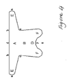
- It is therefore subject of the invention a flat implantable device made of material with a reticular or laminar structure for supporting the female pelvic organs, characterised in that it has a central body with a trapezoid shape having four arms, in which may be distinguished:
- a front portion corresponding to the smaller base of the trapezium, from the ends of which branch off in opposite directions two arms coaxial with each other and parallel to said smaller base;
- a central portion corresponding to the central part of the trapezium;
- a rear portion corresponding to the larger base of the trapezium, from the ends of which branch off two arms diverging from each other and parallel to the sides of the trapezium.
-
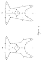
- Figure 1: front view of the present device having a hole in the central portion and the front portion divided into two halves by longitudinal cleft. Figures 1a and 1b differ for dimensions, respectively adapted for bigger and smaller patient body sizes.
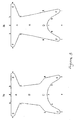
- Figure 2: front view of the present device having a hole in the central portion and the rear portion divided into two halves by longitudinal cleft. Figures 2a and 2b differ for dimensions, respectively adapted for bigger and smaller patient body sizes.
- Figure 3: front view of a device without the hole in the central portion and the longitudinal cleft. Figures 3a and 3b differ for dimensions, respectively adapted for bigger and smaller patient body sizes.
- Figure 4: front view of a device without the hole in the central portion and having the rear arms shorter than in the devices of Figures 1-3.
- As a non limiting example of the invention:
- Figure 1a represents a front view of the device according to the invention constituted by a central body, in which may be distinguished a front portion A intended to hold the prolapsed bladder (cystocele), a rear portion D on which is placed the prolapsed intestine (enterocele), and a central portion B with the hole U which holds the uterus. The portions A, B and D into which the central body is subdivided are suitably shaped and have dimensions such as to be able to hold and support the prolapsed organs.
From the front portion A branch off the two arms E, while from the rear portion D branch off the two arms F; both pairs of arms are suitably shaped and positioned with respect to the longitudinal axis of the device in such a way that they can be anchored, during surgery, to fixed and well identified structures on the patient's pelvis.
In the device represented in Figure 1a the front portion A of the central body is divided into two halves by a longitudinal cleft H, the purpose of which is to divaricate during surgery the device already anchored through the rear arms F, so as to pass the two halves D from opposite sides with respect to the uterus and to be able to place the neck of the uterus more easily in the hole U. - Figure 1 b represents another front view of the device according to the invention,
- The present device may also be realised as in Figure 2a, with the longitudinal cleft H which cuts the rear portion D of the central body in two halves; this device adapts to a type of surgical implant in which the front arms E are anchored first, then the rear part D is divaricated thanks to the cleft H so as to facilitate the entry of the neck of the uterus in the hole U, and lastly the rear arms F are anchored.
- Figure 2b represents the same type of device with the cleft H in the rear portion D shown in Figure 2a, in which the dimensions of the device have been reduced to adapt it to patients of a smaller size.
- A further embodiment of the present device contemplates that the cleft H is present both in the front part and in the rear, thus cutting the device in two halves which are then rejoined at the time of surgery.
- According to a further embodiment of the invention, the present invention has a central hole and a transverse cleft H which, starting from the central hole, cuts the central portion to the right of the hole, or the one to the left, in two halves.
- Figure 3a represents a device not being part of the invention without the central hole U to be used, depending on the dimensions of the rear arms F described in greater detail below, in cases of prolapse of the vaginal vault in patients without uterus, or in cases of partial prolapse.
- Figure 3b represents the same type of device for patients of a smaller size.
- With reference to Figures 1-3, the dimensions of the device according to the invention are for example the following:
- length a-a of the front arms E: between 8.0 and 15 cm; when the device is implanted by means of "tension free" operations, the length a-a is typically between 11 and 15 cm, and is preferably 13 cm; while for all the other types of surgical implant it is typically between 8.0 and 12.0 cm and is preferably 10 cm;
- length b-b of the front portion A: between 2.5 and 6.0 cm, and preferably 3.8 cm;
- length c-c of the front portion A: between 3.0 and 6.0 cm, and preferably 3.8 cm;
- width b-c of the front arms E: between 1.0 and 3.0 cm and preferably 2.0 cm;
- length d-y of the front portion A: between 2.5 and 6.5 cm, and preferably 4.0 cm;
- total length d-z of the device: between 11 and 15 cm, and preferably 12 cm;
- distance y-x in the central hole U: between 0.6 and 1.6 cm, and preferably 1.1 cm;
- distance x-e in the central hole U, the same as or different from the distance y-x: between 0.6 and 1.6 cm, and preferably 1.1 cm;
- length e-f of the rear portion D: between 1.8 and 4.0 cm, and preferably 2.3 cm;
- width x-I: between 0.5 and 4.0, and preferably 2.5 cm;
- distance h-h between the rear arms F: between 1.5 and 7.0 cm; for devices to be implanted in patients of a small size it is typically between 1.5 and 5.5 cm and is preferably 3.5 cm, while for devices to be implanted in patients of a large size it is between 3.0 and 7.0 cm and is preferably 5.0 cm;
- distance g-g between the rear arms F: between 4.9 and 10 cm; for devices to be implanted in patients of a small size it is typically between 4.9 and 8.9 cm and is preferably 6.0 cm, while for devices to be implanted in patients of a large size it is between 6.0 and 10 cm and is preferably 7.6 cm;
- distance i-i between the rear arms F: between 4.5 and 10.5 cm; for devices to be implanted in patients of a small size it is typically between 4.5 and 8.5 cm and is preferably 6.5 cm, while for devices to be implanted in patients of a large size it is between 6.5 and 10.5 cm and is preferably 8.0 cm;
- length h-i of the rear arms F: between 2.5 and 6.5 cm, and preferably 4.5 cm.
- The dimensions of devices not according to the invention without a hole illustrated in Figure 4, are the same as given above for the embodiments illustrated in Figures 1-3, except for the length h-i of the rear arms and therefore for the total length d-z of the device.
- In facts, the device illustrated in Figure 4, depending on whether it is to be implanted in patients with partial prolapse or in patients without uterus with prolapse of the vaginal vault, may have rear arms of different lengths.
- A device suitable in the case of partial prolapse has for example the following dimensions:
- total length d-z of the device: between 4 and 8 cm, and preferably 5.1 cm;
- length h-i of the rear arms F: between 0.5 and 3 cm, and preferably 1.1 cm;
- total length d-z of the device: between 10 and 13 cm, and preferably 11 cm;
- length h-i of the rear arms F: between 2.5 and 6.5 cm, and preferably 4.5 cm.
- The device according to the invention must be made of a material having a reticular or laminar structure, so as not to retain exudates and organic liquids which could build up on the central body of device, in particular in area A.
- Any material having a reticular or laminar structure, whether it be of organic or synthetic origin, is suitable for the realisation of the present device as long as it maintains its structure more or less unchanged over time and remains fixed in the position in which it was inserted during surgery.
- Numerous synthetic materials are currently on the market which could be used to make the present device, for example materials based on single-filament polypropylene for use in surgical implants, in particular the reticular materials composed of mixtures of polypropylene and polyglactin.
- Materials of organic origin that could be used according to the invention are for example membrane of bovine pericardium, human fascia lata, acellular matrix of pig collagen, and submucosa of pig small intestine, suitably treated so as to be sterile and unable to transmit animal pathologies, and to remain more or less unaltered over time.
- Examples of commercial product of organic origin that could be used according to the invention are for example membrane of bovine pericardium treated with glutaraldehyde and heparin, produced by Shelhigh and marketed under the name Dome Pericardial Patch No-React® Treated, pig intestine submucosa produced by DePuy OrthoTech and known by the trade name SIS (small intestine submucosa), or reticular porcine collagen marketed by Bard under the name Pelvicol®.
- The materials of organic origin are preferably used in the realisation of the present device as they are generally well tolerated by the organism, they do not give foreign body reactions, they are soft and impalpable and there is minimum risk of erosion of the tissues with which they come in contact.
- The dimensions of the holes in the materials that may be used according to the invention have a diameter preferably comprised between 0.01 cm and 0.05 cm and more preferably 0.03 cm, at a distance from each other preferably of between 0.06 and 0.1, and more preferably 0.08.
- The present device is applied by surgery; during surgery, the habitual means of access is the vagina, with an incision extending from the front vaginal wall to the rear wall, excluding the neck of the uterus.
- Through the front vaginal wall the tendinous arch of the levator ani is penetrated, which is opened bilaterally for about 2 cm, and on which the two arms E are fixed respectively on the right and on the left.
- The two rear arms F are then passed by the sides of the neck of the uterus, one on the right and one on the left, and are laid until the central part B surrounds the neck of the uterus. The right and the left half of the rear portion of the device are rejoined in the centre with two stitches and the rear arms are fixed bilaterally to the sacrospinous ligament or to the iliococcygeal muscle. At the end of the operation the device, anchored by means of the four arms to the tendinous arch of the levator ani and to the sacrospinous ligament (or to the iliococcygeal muscle), is at the normal anatomical level of the levator ani muscle. Consequently, also the organs resting on it, the bladder at the front (cystocele), the neck of the uterus in the centre (hysterocele, the rectum at the rear (enterocele), are returned to their correct anatomical plane above said muscle.
- The operation can also be carried out by fixing first the two rear arms, using the device in which the cleft extends longitudinally from the central hole, cutting the front portion A.
- Alternatively, the device according to the invention may be used which has the cleft H both in the front part and in the rear, and is therefore composed of two specular halves; in this case the operation is carried out by fixing first one half through the two front and rear arms and then the other half; the two halves already fixed both at the front and at the rear are then rejoined on the front portion A and on the rear portion D, taking care to position the neck of the uterus in the central hole U.
- In the case of the device with a horizontal cleft, the procedures for passing around the neck of the uterus are the same as described above for the devices with a longitudinal cleft, and the suture of the cut of the device will be in a lateral position.
- In patients without uterus, the operation may be carried out using the device represented in Figure 3, fixing first the front arms and then the rear arms, or vice versa.
- Moreover, in patients suffering of a partial prolapse of pelvic organs, the operation may be carried out by using the device illustrated in Figure 4; in this case the vaginal surgery procedure comprises making an incision extending from the front vaginal wall to the cervix; penetrating the tendinous arch of the levator ani through the front vaginal wall; bilaterally opening said tendineous arch for about 2 cm; fixing the two front arms of the said device respectively on the right and on the left on the said opened tendineous arch; and bilaterally fixing the rear short arms to the neck of the uterus.
- All the cases described above may also be realised by means of "tension free" operations, in which the present device is positioned inside the vaginal cavity without fixing it with stitches, but only making dissections in the tendinous arch of the levator ani which guarantee the positioning of the front arms E. In this type of "tension free" operation the device according to the invention must have the opening of the front arms, represented in the figures by the length a-a, between 11 and 15 cm; moreover, it is preferable to use devices made of polypropylene and similar.
- Moreover, as well as by the only vaginal approach, the operation may be carried out with a mixed vaginal/abdominal or vaginal/laparoscopical approach, or by means of mini-invasive surgery.
- The invention being as described, it is clear that this device may be modified in various ways which lie within the scope of the claims.
Claims (17)
- A flat implantable device made of material with a reticular or laminar structure for supporting the female pelvic organs, having a central body with a trapezoid shape with four arms, in which may be distinguished:- a front portion (A) corresponding to the smaller base of the trapezium, from the ends of which branch off two arms (E);- a central portion (B) corresponding to the central part of the trapezium;- a rear portion (D) corresponding to the larger base of the trapezium, from the ends of which branch off two arms (F) diverging from each other and parallel to the sides of the trapezium;characterised in that the said two arms (E) branch off from the front portion (A) in opposite directions and are coaxial with each other and parallel to said smaller base; and the said central portion (B) has a central hole (U) from which starts a cleft (H).
- The device according to claim 1, wherein said cleft (H) longitudinally cuts the rear portion (D) of said central body.
- The device according to claim 1, wherein said cleft (H) longitudinally cuts the front portion (A) of said central body.
- The device according to claim 1, wherein said cleft (H) longitudinally cuts both the front portion (A) and the rear portion (D) of said central body.
- The device according to claim 1, wherein said cleft (H) transversely cuts the right central portion of said central body.
- The device according to claim 1, wherein said cleft (H) transversely cuts the left central portion of said central body.
- The device according to one of the claims 1-6, wherein said material with a reticular or laminar structure is selected from the group consisting of materials of organic origin and materials of a synthetic nature.
- The device according to claim 7, wherein said material of organic origin is selected from the group consisting of membrane of bovine pericardium, human fascia lata, acellular matrix of pig collagen, and submucosa of pig small intestine.
- The device according to claim 8, wherein said membrane of bovine pericardium is treated with glutaraldehyde and heparin.
- The device according to claim 7, wherein said material of a synthetic nature is selected from materials based on single-filament polypropylene.
- The device according to claim 7, wherein said material of synthetic origin is a mixture of polypropylene and polyglactin.
- The device according to claim 7, wherein said material has holes having diameter comprised between 0.01 cm and 0.05 cm, at a distance from each other of between 0.06 and 0.1.
- The device according to claim 7, wherein said material has holes having diameter of 0.03 cm, at a distance from each other of 0.08.
- The device according to claim 1, wherein:- the length a-a of the front arms is between 8.0 and 15 cm;- the length b-b of the front portion is between 2.5 and 6.0 cm;- the length c-c of the front portion is between 3.0 and 6.0 cm;- the width b-c of the front arms is between 1.0 and 3.0 cm;- the length d-y of the front portion is between 2.5 and 6.5 cm;- the total length d-z of the device is between 4 and 8 cm;- the length e-f of the rear portion is between 1.8 and 4.0 cm;- the distance h-h between the rear arms is between 1.5 and 7.0 cm;- the distance g-g between the rear arms is between 4.9 and 10 cm;- the distance i-i between the rear arms is between 4.5 and 10.5 cm;- the length h-i of the rear arms is between 1 and 3 cm.
- The device according to claim 14, wherein:- the length a-a of the front arms is 10 cm;- the length b-b of the front portion is 3.8 cm;- the length c-c of the front portion is 3.8 cm;- the width b-c of the front arms is 2.0 cm;- the length d-y of the front portion is 4.0 cm;- the total length d-z of the device is 6 cm;- the length e-f of the rear portion is 2.7 cm;- the distance h-h between the rear arms is 5.0 cm for patients with a large body size and 3.5 cm for patients with a small size;- the distance g-g between the rear arms is 8.0 cm for patients with a large body size and 6.9 cm for patients with a small size;- the distance i-i between the rear arms is 8.5 cm for patients with a large body size and 6.5 cm for patients with a small size;- the length h-i of the rear arms is 1.5 cm.
- The device according to claim 1, wherein:- the length a-a of the front arms is between 8.0 and 15 cm;- the length b-b of the front portion is between 2.5 and 6.0 cm;- the length c-c of the front portion is between 3.0 and 6.0 cm;- the width b-c of the front arms is between 1.0 and 3.0 cm;- the length d-y of the front portion is between 2.5 and 6.5 cm;- the total length d-z of the device is between 11 and 15 cm;- the distance y-x in the central hole U is between 0.6 and 1.6 cm;- the distance x-e in the central hole U, the same as or different from the distance y-x, is between 0.6 and 1.6 cm;- the length e-f of the rear portion is between 1.8 and 4.0 cm;- the distance h-h between the rear arms is between 1.5 and 7.0 cm;- the distance g-g between the rear arms is between 4.9 and 10 cm;- the distance i-i between the rear arms is between 4.5 and 10.5 cm;- the length h-i of the rear arms is between 2.5 and 6.5 cm.
- The device according to claim 16, wherein:- the length a-a of the front arms is 10 cm;- the length b-b of the front portion is 3.8 cm;- the length c-c of the front portion is 3.8 cm;- the width b-c of the front arms is 2.0 cm;- the length d-y of the front portion is 4.0 cm;- the total length d-z of the device is 12 cm;- the distance y-x in the central hole U is 1.1 cm;- the distance x-e in the central hole U is 1.1 cm;- the length e-f of the rear portion is 2.3 cm;- the distance h-h between the rear arms is 5.0 cm for patients with a large body size and 3.5 cm for patients with a small size;- the distance g-g between the rear arms is 7.6 cm for patients with a large body size and 6.0 cm for patients with a small size;- the distance i-i between the rear arms is 8.5 cm for patients with a large body size and 6.5 cm for patients with a small size;- the length h-i of the rear arms is 4.5 cm.
Applications Claiming Priority (3)
| Application Number | Priority Date | Filing Date | Title |
|---|---|---|---|
| ITFI20020145 | 2002-08-01 | ||
| IT000145A ITFI20020145A1 (en) | 2002-08-01 | 2002-08-01 | DEVICE FOR THE SURGICAL TREATMENT OF FEMALE PROLAXIS. |
| PCT/EP2003/008546 WO2004012626A1 (en) | 2002-08-01 | 2003-08-01 | Device for the surgical treatment of female prolapse |
Publications (2)
| Publication Number | Publication Date |
|---|---|
| EP1549245A1 EP1549245A1 (en) | 2005-07-06 |
| EP1549245B1 true EP1549245B1 (en) | 2008-01-23 |
Family
ID=31198609
Family Applications (1)
| Application Number | Title | Priority Date | Filing Date |
|---|---|---|---|
| EP03766391A Expired - Lifetime EP1549245B1 (en) | 2002-08-01 | 2003-08-01 | Device for the surgical treatment of female prolapse |
Country Status (9)
| Country | Link |
|---|---|
| US (2) | US7985174B2 (en) |
| EP (1) | EP1549245B1 (en) |
| AT (1) | ATE384487T1 (en) |
| AU (1) | AU2003260353A1 (en) |
| CA (1) | CA2493345A1 (en) |
| DE (1) | DE60318870T2 (en) |
| ES (1) | ES2301834T3 (en) |
| IT (1) | ITFI20020145A1 (en) |
| WO (1) | WO2004012626A1 (en) |
Cited By (5)
| Publication number | Priority date | Publication date | Assignee | Title |
|---|---|---|---|---|
| EP2402045A2 (en) | 2010-06-25 | 2012-01-04 | Aesculap AG | Medical product, in particular for management of tissue repair |
| US8123671B2 (en) | 2005-08-04 | 2012-02-28 | C.R. Bard, Inc. | Pelvic implant systems and methods |
| US8480559B2 (en) | 2006-09-13 | 2013-07-09 | C. R. Bard, Inc. | Urethral support system |
| US8574149B2 (en) | 2007-11-13 | 2013-11-05 | C. R. Bard, Inc. | Adjustable tissue support member |
| US8845512B2 (en) | 2005-11-14 | 2014-09-30 | C. R. Bard, Inc. | Sling anchor system |
Families Citing this family (88)
| Publication number | Priority date | Publication date | Assignee | Title |
|---|---|---|---|---|
| SE506164C2 (en) | 1995-10-09 | 1997-11-17 | Medscand Medical Ab | Instruments for the treatment of urinary incontinence in women |
| US7121997B2 (en) | 1999-06-09 | 2006-10-17 | Ethicon, Inc. | Surgical instrument and method for treating female urinary incontinence |
| ATE506021T1 (en) | 1999-06-09 | 2011-05-15 | Ethicon Inc | DEVICE FOR ADJUSTING POLYMER IMPLANTS TO SOFT SURFACES |
| FR2811218B1 (en) | 2000-07-05 | 2003-02-28 | Patrice Suslian | IMPLANTABLE DEVICE FOR CORRECTING URINARY INCONTINENCE |
| US20060205995A1 (en) | 2000-10-12 | 2006-09-14 | Gyne Ideas Limited | Apparatus and method for treating female urinary incontinence |
| GB0025068D0 (en) | 2000-10-12 | 2000-11-29 | Browning Healthcare Ltd | Apparatus and method for treating female urinary incontinence |
| US8167785B2 (en) | 2000-10-12 | 2012-05-01 | Coloplast A/S | Urethral support system |
| GB0108088D0 (en) | 2001-03-30 | 2001-05-23 | Browning Healthcare Ltd | Surgical implant |
| ES2393426T3 (en) * | 2002-03-01 | 2012-12-21 | Ethicon, Inc. | Device for treating pelvic organ prolapse in female patients |
| ATE487427T1 (en) | 2002-08-02 | 2010-11-15 | Bard Inc C R | SELF-ANCHORING LOOSE AND INTRODUCTION SYSTEM |
| GB0307082D0 (en) | 2003-03-27 | 2003-04-30 | Gyne Ideas Ltd | Drug delivery device and method |
| BRPI0408903A (en) * | 2003-03-28 | 2006-03-28 | Analytic Biosurgical Solutions | implant for treatment of the rectocele and / or vaginal dome prolapse, device for inserting an implant and process for treating the rectocele in a woman |
| US7393319B2 (en) * | 2003-10-14 | 2008-07-01 | Caldera Medical, Inc. | Implantable sling having bladder support |
| US8047982B2 (en) | 2004-05-07 | 2011-11-01 | Ethicon, Inc. | Mesh tape with wing-like extensions for treating female urinary incontinence |
| GB0411360D0 (en) | 2004-05-21 | 2004-06-23 | Mpathy Medical Devices Ltd | Implant |
| DE102004025404A1 (en) * | 2004-05-24 | 2005-12-22 | Serag-Wiessner Kg | Implant for suspension of the bladder in urinary incontinence of the woman |
| EP2543341B1 (en) | 2004-06-14 | 2016-07-20 | Boston Scientific Limited | A soft tissue anchor |
| WO2006015031A2 (en) | 2004-07-28 | 2006-02-09 | Ethicon, Inc. | Minimally invasive medical implant and insertion device and method for using the same |
| WO2006034719A1 (en) * | 2004-09-28 | 2006-04-06 | Negm Sherif Mohammed Maher Ibr | Vaginal stent for prevention and treatment of vaginal vault prolapse |
| AU2005294479B2 (en) * | 2004-10-05 | 2011-08-18 | Ams Research Corporation | Device and method for supporting vaginal cuff |
| US7740576B2 (en) | 2005-04-05 | 2010-06-22 | Ams Research Corporation | Articles, devices, and methods for pelvic surgery |
| US20060229596A1 (en) | 2005-04-06 | 2006-10-12 | Boston Scientific Scimed, Inc. | Systems, devices, and methods for treating pelvic floor disorders |
| US8109866B2 (en) | 2005-04-26 | 2012-02-07 | Ams Research Corporation | Method and apparatus for prolapse repair |
| EP1909687A1 (en) | 2005-07-13 | 2008-04-16 | Boston Scientific Scimed, Inc. | Snap fit sling anchor system and related methods |
| US7878969B2 (en) | 2005-07-25 | 2011-02-01 | Boston Scientific Scimed, Inc. | Pelvic floor repair system |
| AU2006275977B2 (en) | 2005-07-26 | 2012-08-30 | Ams Research Corporation | Methods and systems for treatment of prolapse |
| US7878970B2 (en) | 2005-09-28 | 2011-02-01 | Boston Scientific Scimed, Inc. | Apparatus and method for suspending a uterus |
| EP1957008B8 (en) * | 2005-12-09 | 2012-08-22 | Promedon SA | Implant for treating stress urinary incontinence and anterior vaginal wall prolapse |
| WO2007080519A2 (en) * | 2006-01-10 | 2007-07-19 | Ajay Rane | Multi-leveled transgluteal tension-free levatorplasty for treatment of rectocele |
| KR20080108410A (en) * | 2006-01-10 | 2008-12-15 | 앨튼 브이. 홀럼 | Levator for repair of perineal prolapse |
| US9144483B2 (en) | 2006-01-13 | 2015-09-29 | Boston Scientific Scimed, Inc. | Placing fixation devices |
| CA2908132C (en) | 2006-02-16 | 2018-12-11 | Ams Research Corporation | Surgical articles and methods for treating pelvic conditions |
| WO2007109062A2 (en) * | 2006-03-15 | 2007-09-27 | C.R. Bard, Inc. | Implants for the treatment of pelvic floor disorders |
| WO2007109508A1 (en) * | 2006-03-16 | 2007-09-27 | Boston Scientific Limited | System and method for treating tissue wall prolapse |
| AU2007240139A1 (en) * | 2006-04-14 | 2007-10-25 | A.M.I. Agency For Medical Innovations Gmbh | Implantable mesh for surgical reconstruction in the area of the pelvic floor |
| US9084664B2 (en) | 2006-05-19 | 2015-07-21 | Ams Research Corporation | Method and articles for treatment of stress urinary incontinence |
| EP2029048A2 (en) * | 2006-06-16 | 2009-03-04 | AMS Research Corporation | Surgical implants and tools for treating pelvic conditions |
| EP2049039A2 (en) | 2006-06-22 | 2009-04-22 | AMS Research Corporation | Adjustable tension incontinence sling assemblies |
| WO2008013867A1 (en) | 2006-07-25 | 2008-01-31 | Ams Research Corporation | Surgical articles and methods for treating pelvic conditions |
| JP5129258B2 (en) * | 2006-10-26 | 2013-01-30 | エーエムエス リサーチ コーポレイション | Surgical apparatus and method for treating pelvic disease |
| WO2008058163A2 (en) | 2006-11-06 | 2008-05-15 | Caldera Medical, Inc. | Implants and procedures for treatment of pelvic floor disorders |
| US8597173B2 (en) | 2007-07-27 | 2013-12-03 | Ams Research Corporation | Pelvic floor treatments and related tools and implants |
| US8623034B2 (en) | 2007-10-19 | 2014-01-07 | Ethicon, Gmbh | Soft tissue repair implant |
| US20090171141A1 (en) * | 2007-12-27 | 2009-07-02 | Chu Michael S H | Anterior Repair - Needle Path and Incision Sites |
| AU2009200974B2 (en) | 2008-03-14 | 2014-06-12 | Ams Research Corporation | Apparatus and method for repairing vaginal reconstruction |
| US8727963B2 (en) | 2008-07-31 | 2014-05-20 | Ams Research Corporation | Methods and implants for treating urinary incontinence |
| US9017243B2 (en) | 2008-08-25 | 2015-04-28 | Ams Research Corporation | Minimally invasive implant and method |
| WO2010027796A1 (en) | 2008-08-25 | 2010-03-11 | Ams Research Corporation | Minimally invasive implant and method |
| US8449573B2 (en) | 2008-12-05 | 2013-05-28 | Boston Scientific Scimed, Inc. | Insertion device and method for delivery of a mesh carrier |
| CA2747607C (en) | 2009-01-05 | 2017-05-23 | Caldera Medical, Inc. | Implants and procedures for supporting anatomical structures for treating conditions such as pelvic organ prolapse |
| US8968334B2 (en) | 2009-04-17 | 2015-03-03 | Boston Scientific Scimed, Inc. | Apparatus for delivering and anchoring implantable medical devices |
| US9301750B2 (en) | 2009-11-03 | 2016-04-05 | Boston Scientific Scimed, Inc. | Device and method for delivery of mesh-based devices |
| US9414902B2 (en) | 2009-11-04 | 2016-08-16 | Boston Scientific Scimed, Inc. | Method for treating prolapse and incontinence |
| WO2011082287A1 (en) | 2009-12-30 | 2011-07-07 | Ams Research Corporation | Implant systems with tensioning feedback |
| CN102740797A (en) | 2009-12-30 | 2012-10-17 | Ams研究股份有限公司 | Elongate implant system and method for treating pelvic conditions |
| US10028813B2 (en) | 2010-07-22 | 2018-07-24 | Boston Scientific Scimed, Inc. | Coated pelvic implant device and method |
| US8911348B2 (en) | 2010-09-02 | 2014-12-16 | Boston Scientific Scimed, Inc. | Pelvic implants and methods of implanting the same |
| US9572648B2 (en) | 2010-12-21 | 2017-02-21 | Justin M. Crank | Implantable slings and anchor systems |
| US9125717B2 (en) | 2011-02-23 | 2015-09-08 | Ams Research Corporation | Implant tension adjustment system and method |
| EP2678068A4 (en) | 2011-02-23 | 2014-10-01 | Ams Res Corp | Drug releasing pelvic treatment system and method |
| US8808162B2 (en) | 2011-03-28 | 2014-08-19 | Ams Research Corporation | Implants, tools, and methods for treatment of pelvic conditions |
| US9750590B2 (en) | 2011-03-28 | 2017-09-05 | Andrew P. VanDeWeghe | Implants, tools, and methods for treatment of pelvic conditions |
| US9492259B2 (en) | 2011-03-30 | 2016-11-15 | Astora Women's Health, Llc | Expandable implant system |
| US9636201B2 (en) | 2011-05-12 | 2017-05-02 | Boston Scientific Scimed, Inc. | Delivery members for delivering an implant into a body of a patient |
| US9113991B2 (en) | 2011-05-12 | 2015-08-25 | Boston Scientific Scimed, Inc. | Anchors for bodily implants and methods for anchoring bodily implants into a patient's body |
| US10058240B2 (en) | 2011-06-29 | 2018-08-28 | Boston Scientific Scimed, Inc. | Systems, implants, tools, and methods for treatments of pelvic conditions |
| US20130006049A1 (en) | 2011-06-30 | 2013-01-03 | Alexander James A | Implants, tools, and methods for treatments of pelvic conditions |
| US9351723B2 (en) | 2011-06-30 | 2016-05-31 | Astora Women's Health, Llc | Implants, tools, and methods for treatments of pelvic conditions |
| EP2734148B1 (en) | 2011-07-22 | 2019-06-05 | Boston Scientific Scimed, Inc. | Pelvic implant system |
| US9414903B2 (en) | 2011-07-22 | 2016-08-16 | Astora Women's Health, Llc | Pelvic implant system and method |
| US9492191B2 (en) | 2011-08-04 | 2016-11-15 | Astora Women's Health, Llc | Tools and methods for treatment of pelvic conditions |
| US20130035555A1 (en) | 2011-08-05 | 2013-02-07 | Alexander James A | Systems, implants, tools, and methods for treatment of pelvic conditions |
| US8864647B2 (en) | 2011-08-19 | 2014-10-21 | Coloplast A/S | Incontinence treatment device with pubic arm attachment mechanism |
| US10098721B2 (en) | 2011-09-01 | 2018-10-16 | Boston Scientific Scimed, Inc. | Pelvic implant needle system and method |
| USD721175S1 (en) | 2011-09-08 | 2015-01-13 | Ams Research Corporation | Backers for surgical indicators |
| USD736382S1 (en) | 2011-09-08 | 2015-08-11 | Ams Research Corporation | Surgical indicator with backers |
| USD721807S1 (en) | 2011-09-08 | 2015-01-27 | Ams Research Corporation | Surgical indicators |
| US9168120B2 (en) | 2011-09-09 | 2015-10-27 | Boston Scientific Scimed, Inc. | Medical device and methods of delivering the medical device |
| US10265152B2 (en) | 2011-10-13 | 2019-04-23 | Boston Scientific Scimed, Inc. | Pelvic implant sizing systems and methods |
| US9192458B2 (en) | 2012-02-09 | 2015-11-24 | Ams Research Corporation | Implants, tools, and methods for treatments of pelvic conditions |
| US10111651B2 (en) | 2012-11-02 | 2018-10-30 | Coloplast A/S | System and method of anchoring support material to tissue |
| US9241779B2 (en) | 2012-11-02 | 2016-01-26 | Coloplast A/S | Male incontinence treatment system |
| US10039627B2 (en) | 2013-03-11 | 2018-08-07 | Boston Scientific Scimed, Inc. | Medical device and method of delivering the medical device |
| US9814555B2 (en) | 2013-03-12 | 2017-11-14 | Boston Scientific Scimed, Inc. | Medical device for pelvic floor repair and method of delivering the medical device |
| WO2014178979A2 (en) * | 2013-05-03 | 2014-11-06 | Cullison James W | Urological Implant |
| US9480546B2 (en) | 2013-08-05 | 2016-11-01 | Coloplast A/S | Hysteropexy mesh apparatuses and methods |
| US9757221B2 (en) | 2013-09-16 | 2017-09-12 | Boston Scientific Scimed, Inc. | Medical device and method of making the same |
| CN107348976B (en) * | 2017-05-19 | 2019-11-19 | 薛运章 | A kind of mesenterium support device and method for supporting |
Family Cites Families (10)
| Publication number | Priority date | Publication date | Assignee | Title |
|---|---|---|---|---|
| DE19544162C1 (en) * | 1995-11-17 | 1997-04-24 | Ethicon Gmbh | Implant for suspension of the bladder in urinary incontinence in women |
| US6042534A (en) * | 1997-02-13 | 2000-03-28 | Scimed Life Systems, Inc. | Stabilization sling for use in minimally invasive pelvic surgery |
| FR2792824B1 (en) * | 1999-04-27 | 2001-06-22 | Sofradim Production | DEVICE FOR TREATING PROLAPSUS BY VAGINAL SUSPENSION |
| US6355065B1 (en) * | 1999-09-01 | 2002-03-12 | Shlomo Gabbay | Implantable support apparatus and method of using same |
| US6374141B1 (en) * | 1999-10-08 | 2002-04-16 | Microhelix, Inc. | Multi-lead bioelectrical stimulus cable |
| US6436030B2 (en) * | 2000-01-31 | 2002-08-20 | Om P. Rehil | Hiatal hernia repair patch and method for using the same |
| DE10056169C2 (en) * | 2000-11-13 | 2003-07-03 | Ethicon Gmbh | Implant for holding the female bladder |
| US6612977B2 (en) | 2001-01-23 | 2003-09-02 | American Medical Systems Inc. | Sling delivery system and method of use |
| US6652450B2 (en) * | 2001-01-23 | 2003-11-25 | American Medical Systems, Inc. | Implantable article and method for treating urinary incontinence using means for repositioning the implantable article |
| US6736823B2 (en) * | 2002-05-10 | 2004-05-18 | C.R. Bard, Inc. | Prosthetic repair fabric |
-
2002
- 2002-08-01 IT IT000145A patent/ITFI20020145A1/en unknown
-
2003
- 2003-08-01 AU AU2003260353A patent/AU2003260353A1/en not_active Abandoned
- 2003-08-01 ES ES03766391T patent/ES2301834T3/en not_active Expired - Lifetime
- 2003-08-01 CA CA002493345A patent/CA2493345A1/en not_active Abandoned
- 2003-08-01 EP EP03766391A patent/EP1549245B1/en not_active Expired - Lifetime
- 2003-08-01 AT AT03766391T patent/ATE384487T1/en not_active IP Right Cessation
- 2003-08-01 US US10/523,144 patent/US7985174B2/en not_active Expired - Fee Related
- 2003-08-01 WO PCT/EP2003/008546 patent/WO2004012626A1/en active Search and Examination
- 2003-08-01 DE DE60318870T patent/DE60318870T2/en not_active Expired - Lifetime
-
2011
- 2011-07-05 US US13/176,426 patent/US20110282137A1/en not_active Abandoned
Cited By (5)
| Publication number | Priority date | Publication date | Assignee | Title |
|---|---|---|---|---|
| US8123671B2 (en) | 2005-08-04 | 2012-02-28 | C.R. Bard, Inc. | Pelvic implant systems and methods |
| US8845512B2 (en) | 2005-11-14 | 2014-09-30 | C. R. Bard, Inc. | Sling anchor system |
| US8480559B2 (en) | 2006-09-13 | 2013-07-09 | C. R. Bard, Inc. | Urethral support system |
| US8574149B2 (en) | 2007-11-13 | 2013-11-05 | C. R. Bard, Inc. | Adjustable tissue support member |
| EP2402045A2 (en) | 2010-06-25 | 2012-01-04 | Aesculap AG | Medical product, in particular for management of tissue repair |
Also Published As
| Publication number | Publication date |
|---|---|
| CA2493345A1 (en) | 2004-02-12 |
| WO2004012626A1 (en) | 2004-02-12 |
| DE60318870D1 (en) | 2008-03-13 |
| ATE384487T1 (en) | 2008-02-15 |
| ITFI20020145A1 (en) | 2004-02-02 |
| DE60318870T2 (en) | 2009-01-29 |
| US7985174B2 (en) | 2011-07-26 |
| US20110282137A1 (en) | 2011-11-17 |
| US20060134159A1 (en) | 2006-06-22 |
| AU2003260353A1 (en) | 2004-02-23 |
| ES2301834T3 (en) | 2008-07-01 |
| EP1549245A1 (en) | 2005-07-06 |
Similar Documents
| Publication | Publication Date | Title |
|---|---|---|
| EP1549245B1 (en) | Device for the surgical treatment of female prolapse | |
| US6306079B1 (en) | Mesh pubovaginal sling | |
| EP2250973B1 (en) | Kit for surgical repair of vagina damaged by pelvic organ prolapse | |
| AU2005294479B2 (en) | Device and method for supporting vaginal cuff | |
| US7645227B2 (en) | Implants and methods for pelvic floor repair | |
| US7981024B2 (en) | Pelvic implant with anchoring frame | |
| US20100121460A1 (en) | Prosthesis for the treatment of urinary incontinence | |
| JP2006525097A (en) | Prosthesis used for surgical treatment of urogenital prolapse and female urinary incontinence | |
| CN102196783A (en) | Pelvic implant system and method | |
| EP2146647B1 (en) | Instruments for implanting implantable prostheses | |
| AU2003275782B2 (en) | Method of surgical repair of vagina damaged by pelvic organ prolapse and prosthetic materials and devices suitable for use therein | |
| Schreiter | Artificial urinary sphincter: bladder neck, bulbar, membranous, and double cuff implantation |
Legal Events
| Date | Code | Title | Description |
|---|---|---|---|
| PUAI | Public reference made under article 153(3) epc to a published international application that has entered the european phase |
Free format text: ORIGINAL CODE: 0009012 |
|
| 17P | Request for examination filed |
Effective date: 20050225 |
|
| AK | Designated contracting states |
Kind code of ref document: A1 Designated state(s): AT BE BG CH CY CZ DE DK EE ES FI FR GB GR HU IE IT LI LU MC NL PT RO SE SI SK TR |
|
| AX | Request for extension of the european patent |
Extension state: AL LT LV MK |
|
| DAX | Request for extension of the european patent (deleted) | ||
| GRAP | Despatch of communication of intention to grant a patent |
Free format text: ORIGINAL CODE: EPIDOSNIGR1 |
|
| GRAS | Grant fee paid |
Free format text: ORIGINAL CODE: EPIDOSNIGR3 |
|
| GRAA | (expected) grant |
Free format text: ORIGINAL CODE: 0009210 |
|
| AK | Designated contracting states |
Kind code of ref document: B1 Designated state(s): AT BE BG CH CY CZ DE DK EE ES FI FR GB GR HU IE IT LI LU MC NL PT RO SE SI SK TR |
|
| REG | Reference to a national code |
Ref country code: GB Ref legal event code: FG4D |
|
| REG | Reference to a national code |
Ref country code: CH Ref legal event code: EP |
|
| REG | Reference to a national code |
Ref country code: IE Ref legal event code: FG4D |
|
| REF | Corresponds to: |
Ref document number: 60318870 Country of ref document: DE Date of ref document: 20080313 Kind code of ref document: P |
|
| REG | Reference to a national code |
Ref country code: SE Ref legal event code: TRGR |
|
| NLV1 | Nl: lapsed or annulled due to failure to fulfill the requirements of art. 29p and 29m of the patents act | ||
| REG | Reference to a national code |
Ref country code: ES Ref legal event code: FG2A Ref document number: 2301834 Country of ref document: ES Kind code of ref document: T3 |
|
| PG25 | Lapsed in a contracting state [announced via postgrant information from national office to epo] |
Ref country code: LI Free format text: LAPSE BECAUSE OF FAILURE TO SUBMIT A TRANSLATION OF THE DESCRIPTION OR TO PAY THE FEE WITHIN THE PRESCRIBED TIME-LIMIT Effective date: 20080123 Ref country code: FI Free format text: LAPSE BECAUSE OF FAILURE TO SUBMIT A TRANSLATION OF THE DESCRIPTION OR TO PAY THE FEE WITHIN THE PRESCRIBED TIME-LIMIT Effective date: 20080123 Ref country code: CH Free format text: LAPSE BECAUSE OF FAILURE TO SUBMIT A TRANSLATION OF THE DESCRIPTION OR TO PAY THE FEE WITHIN THE PRESCRIBED TIME-LIMIT Effective date: 20080123 |
|
| REG | Reference to a national code |
Ref country code: CH Ref legal event code: PL |
|
| PG25 | Lapsed in a contracting state [announced via postgrant information from national office to epo] |
Ref country code: AT Free format text: LAPSE BECAUSE OF FAILURE TO SUBMIT A TRANSLATION OF THE DESCRIPTION OR TO PAY THE FEE WITHIN THE PRESCRIBED TIME-LIMIT Effective date: 20080123 Ref country code: BG Free format text: LAPSE BECAUSE OF FAILURE TO SUBMIT A TRANSLATION OF THE DESCRIPTION OR TO PAY THE FEE WITHIN THE PRESCRIBED TIME-LIMIT Effective date: 20080423 |
|
| ET | Fr: translation filed | ||
| PG25 | Lapsed in a contracting state [announced via postgrant information from national office to epo] |
Ref country code: PT Free format text: LAPSE BECAUSE OF FAILURE TO SUBMIT A TRANSLATION OF THE DESCRIPTION OR TO PAY THE FEE WITHIN THE PRESCRIBED TIME-LIMIT Effective date: 20080623 Ref country code: SI Free format text: LAPSE BECAUSE OF FAILURE TO SUBMIT A TRANSLATION OF THE DESCRIPTION OR TO PAY THE FEE WITHIN THE PRESCRIBED TIME-LIMIT Effective date: 20080123 Ref country code: BE Free format text: LAPSE BECAUSE OF FAILURE TO SUBMIT A TRANSLATION OF THE DESCRIPTION OR TO PAY THE FEE WITHIN THE PRESCRIBED TIME-LIMIT Effective date: 20080123 |
|
| PG25 | Lapsed in a contracting state [announced via postgrant information from national office to epo] |
Ref country code: NL Free format text: LAPSE BECAUSE OF FAILURE TO SUBMIT A TRANSLATION OF THE DESCRIPTION OR TO PAY THE FEE WITHIN THE PRESCRIBED TIME-LIMIT Effective date: 20080123 Ref country code: DK Free format text: LAPSE BECAUSE OF FAILURE TO SUBMIT A TRANSLATION OF THE DESCRIPTION OR TO PAY THE FEE WITHIN THE PRESCRIBED TIME-LIMIT Effective date: 20080123 Ref country code: CZ Free format text: LAPSE BECAUSE OF FAILURE TO SUBMIT A TRANSLATION OF THE DESCRIPTION OR TO PAY THE FEE WITHIN THE PRESCRIBED TIME-LIMIT Effective date: 20080123 Ref country code: SK Free format text: LAPSE BECAUSE OF FAILURE TO SUBMIT A TRANSLATION OF THE DESCRIPTION OR TO PAY THE FEE WITHIN THE PRESCRIBED TIME-LIMIT Effective date: 20080123 |
|
| PG25 | Lapsed in a contracting state [announced via postgrant information from national office to epo] |
Ref country code: RO Free format text: LAPSE BECAUSE OF FAILURE TO SUBMIT A TRANSLATION OF THE DESCRIPTION OR TO PAY THE FEE WITHIN THE PRESCRIBED TIME-LIMIT Effective date: 20080123 |
|
| PLBE | No opposition filed within time limit |
Free format text: ORIGINAL CODE: 0009261 |
|
| STAA | Information on the status of an ep patent application or granted ep patent |
Free format text: STATUS: NO OPPOSITION FILED WITHIN TIME LIMIT |
|
| 26N | No opposition filed |
Effective date: 20081024 |
|
| PG25 | Lapsed in a contracting state [announced via postgrant information from national office to epo] |
Ref country code: MC Free format text: LAPSE BECAUSE OF NON-PAYMENT OF DUE FEES Effective date: 20080831 |
|
| PG25 | Lapsed in a contracting state [announced via postgrant information from national office to epo] |
Ref country code: EE Free format text: LAPSE BECAUSE OF FAILURE TO SUBMIT A TRANSLATION OF THE DESCRIPTION OR TO PAY THE FEE WITHIN THE PRESCRIBED TIME-LIMIT Effective date: 20080123 |
|
| PG25 | Lapsed in a contracting state [announced via postgrant information from national office to epo] |
Ref country code: IE Free format text: LAPSE BECAUSE OF NON-PAYMENT OF DUE FEES Effective date: 20080801 Ref country code: CY Free format text: LAPSE BECAUSE OF FAILURE TO SUBMIT A TRANSLATION OF THE DESCRIPTION OR TO PAY THE FEE WITHIN THE PRESCRIBED TIME-LIMIT Effective date: 20080123 |
|
| PG25 | Lapsed in a contracting state [announced via postgrant information from national office to epo] |
Ref country code: IT Free format text: LAPSE BECAUSE OF NON-PAYMENT OF DUE FEES Effective date: 20080801 |
|
| PG25 | Lapsed in a contracting state [announced via postgrant information from national office to epo] |
Ref country code: HU Free format text: LAPSE BECAUSE OF FAILURE TO SUBMIT A TRANSLATION OF THE DESCRIPTION OR TO PAY THE FEE WITHIN THE PRESCRIBED TIME-LIMIT Effective date: 20080724 Ref country code: LU Free format text: LAPSE BECAUSE OF NON-PAYMENT OF DUE FEES Effective date: 20080801 |
|
| PG25 | Lapsed in a contracting state [announced via postgrant information from national office to epo] |
Ref country code: TR Free format text: LAPSE BECAUSE OF FAILURE TO SUBMIT A TRANSLATION OF THE DESCRIPTION OR TO PAY THE FEE WITHIN THE PRESCRIBED TIME-LIMIT Effective date: 20080123 |
|
| PG25 | Lapsed in a contracting state [announced via postgrant information from national office to epo] |
Ref country code: GR Free format text: LAPSE BECAUSE OF FAILURE TO SUBMIT A TRANSLATION OF THE DESCRIPTION OR TO PAY THE FEE WITHIN THE PRESCRIBED TIME-LIMIT Effective date: 20080424 |
|
| PGRI | Patent reinstated in contracting state [announced from national office to epo] |
Ref country code: IT Effective date: 20110616 |
|
| REG | Reference to a national code |
Ref country code: FR Ref legal event code: PLFP Year of fee payment: 13 |
|
| PGFP | Annual fee paid to national office [announced via postgrant information from national office to epo] |
Ref country code: IT Payment date: 20160222 Year of fee payment: 13 Ref country code: DE Payment date: 20160216 Year of fee payment: 13 Ref country code: ES Payment date: 20160211 Year of fee payment: 13 |
|
| PGFP | Annual fee paid to national office [announced via postgrant information from national office to epo] |
Ref country code: SE Payment date: 20160209 Year of fee payment: 13 Ref country code: FR Payment date: 20160225 Year of fee payment: 13 Ref country code: GB Payment date: 20160209 Year of fee payment: 13 |
|
| REG | Reference to a national code |
Ref country code: DE Ref legal event code: R119 Ref document number: 60318870 Country of ref document: DE |
|
| REG | Reference to a national code |
Ref country code: SE Ref legal event code: EUG |
|
| GBPC | Gb: european patent ceased through non-payment of renewal fee |
Effective date: 20160801 |
|
| PG25 | Lapsed in a contracting state [announced via postgrant information from national office to epo] |
Ref country code: SE Free format text: LAPSE BECAUSE OF NON-PAYMENT OF DUE FEES Effective date: 20160802 |
|
| REG | Reference to a national code |
Ref country code: FR Ref legal event code: ST Effective date: 20170428 |
|
| PG25 | Lapsed in a contracting state [announced via postgrant information from national office to epo] |
Ref country code: FR Free format text: LAPSE BECAUSE OF NON-PAYMENT OF DUE FEES Effective date: 20160831 Ref country code: DE Free format text: LAPSE BECAUSE OF NON-PAYMENT OF DUE FEES Effective date: 20170301 Ref country code: GB Free format text: LAPSE BECAUSE OF NON-PAYMENT OF DUE FEES Effective date: 20160801 |
|
| PG25 | Lapsed in a contracting state [announced via postgrant information from national office to epo] |
Ref country code: IT Free format text: LAPSE BECAUSE OF NON-PAYMENT OF DUE FEES Effective date: 20160801 |
|
| PG25 | Lapsed in a contracting state [announced via postgrant information from national office to epo] |
Ref country code: ES Free format text: LAPSE BECAUSE OF NON-PAYMENT OF DUE FEES Effective date: 20160802 |
|
| REG | Reference to a national code |
Ref country code: ES Ref legal event code: FD2A Effective date: 20181128 |