EP1548953A1 - Spread spectrum rake receiver - Google Patents
Spread spectrum rake receiver Download PDFInfo
- Publication number
- EP1548953A1 EP1548953A1 EP02760830A EP02760830A EP1548953A1 EP 1548953 A1 EP1548953 A1 EP 1548953A1 EP 02760830 A EP02760830 A EP 02760830A EP 02760830 A EP02760830 A EP 02760830A EP 1548953 A1 EP1548953 A1 EP 1548953A1
- Authority
- EP
- European Patent Office
- Prior art keywords
- mics
- interference
- path
- timing
- signal
- Prior art date
- Legal status (The legal status is an assumption and is not a legal conclusion. Google has not performed a legal analysis and makes no representation as to the accuracy of the status listed.)
- Granted
Links
Images




Classifications
-
- H—ELECTRICITY
- H04—ELECTRIC COMMUNICATION TECHNIQUE
- H04B—TRANSMISSION
- H04B1/00—Details of transmission systems, not covered by a single one of groups H04B3/00 - H04B13/00; Details of transmission systems not characterised by the medium used for transmission
- H04B1/69—Spread spectrum techniques
- H04B1/707—Spread spectrum techniques using direct sequence modulation
- H04B1/7097—Interference-related aspects
- H04B1/711—Interference-related aspects the interference being multi-path interference
- H04B1/7115—Constructive combining of multi-path signals, i.e. RAKE receivers
-
- H—ELECTRICITY
- H04—ELECTRIC COMMUNICATION TECHNIQUE
- H04B—TRANSMISSION
- H04B1/00—Details of transmission systems, not covered by a single one of groups H04B3/00 - H04B13/00; Details of transmission systems not characterised by the medium used for transmission
- H04B1/69—Spread spectrum techniques
- H04B1/707—Spread spectrum techniques using direct sequence modulation
- H04B1/7097—Interference-related aspects
- H04B1/7103—Interference-related aspects the interference being multiple access interference
- H04B1/7107—Subtractive interference cancellation
-
- H—ELECTRICITY
- H04—ELECTRIC COMMUNICATION TECHNIQUE
- H04B—TRANSMISSION
- H04B1/00—Details of transmission systems, not covered by a single one of groups H04B3/00 - H04B13/00; Details of transmission systems not characterised by the medium used for transmission
- H04B1/69—Spread spectrum techniques
- H04B1/707—Spread spectrum techniques using direct sequence modulation
- H04B1/7097—Interference-related aspects
- H04B1/711—Interference-related aspects the interference being multi-path interference
- H04B1/7115—Constructive combining of multi-path signals, i.e. RAKE receivers
- H04B1/712—Weighting of fingers for combining, e.g. amplitude control or phase rotation using an inner loop
Definitions
- the present invention relates generally to a spread spectrum scheme, and more particularly, to a rake receiver that executes, as a reception diversity scheme in a multi-path environment, maximal-ratio composition in the time domain of signals arriving at an antenna with various differences in delay time thereof caused by multiple reflections of propagation paths of the signals.
- Spread spectrum or spread spectrum communication scheme is utilized extensively as a basic technique for mobile communication.
- DS direct spread
- an information signal is transmitted to the receiving side after the spectrum of the information signal is spread by modulating, that is, multiplying the information signal to be transmitted by a PN signal having the chip width Tc of 1/100 to 1/1000 of the cycle T of the information signal to be transmitted as a spread signal.
- the inverse spreading basically refers to executing demodulation by multiplying a received signal by a same PN signal having the same phase as that of the PN signal in the received signal.
- a rake scheme can be listed.
- “Rake” means a rake in English and the rake scheme is a diversity scheme for executing the maximal-ratio composition by collecting power dispersed due to the delay dispersion of transmission paths, into one like a "rake”.
- a desired signal is demodulated by finding a plurality of path timings at which multiple paths arrive using a known signal, informing a demodulator of these path timings, executing inverse spreading at these timings in the demodulator and composing signals of the multiple paths.
- Fig. 1 is a block diagram showing generally an example of the construction of a rake receiver as, for example, a mobile communication terminal.
- the receiver has an antenna 100, a wireless receiving unit 101, an A/D converting unit 102, a searcher 103 for detecting a plurality of timings of the multiple paths and an inverse spreading timing generating and inverse spreading unit 104 for executing an inverse spreading to the plurality of paths according to the timings of the plurality of paths detected by the searcher 103.
- the receiver further has a signal composing unit 105 for composing signals of the plurality of paths obtained by the inverse spreading timing generating and inverse spreading unit 104, a signal processing unit 106 such as a channel codec for receiving an output of the signal composing unit 105 and outputting received signals to a display, speaker, etc., and a level measuring unit 107 for measuring the level of the received signals of the plurality of paths, providing reliability degree information and signal level information to the signal composing unit 105 and providing to a transmission unit 108 control information of transmission power to a base station.
- a signal composing unit 105 for composing signals of the plurality of paths obtained by the inverse spreading timing generating and inverse spreading unit 104
- a signal processing unit 106 such as a channel codec for receiving an output of the signal composing unit 105 and outputting received signals to a display, speaker, etc.
- a level measuring unit 107 for measuring the level of the received signals of the plurality of paths, providing reliability degree information and signal level information to the signal composing
- the transmission unit 108 transmits input from a keyboard or a microphone, from the antenna 100 through a duplexer 109 in response to the control information from the level measuring unit 107.
- Fig. 2 is a block diagram of the detailed construction of the inverse spreading timing generating and inverse spreading unit 104 of Fig. 1, that is, a signal demodulating unit.
- the signal demodulating unit comprises a spread code generator 110, a plurality of delay control units 111-1 to 111-n and a plurality of correlators 112-1 to 112-n corresponding thereto.
- the spread code generator 110 generates a code for inverse spreading.
- the plurality of delay control units 111-1 to 111-n control respectively delay operations of the plurality of correlators 112-1 to 112-n corresponding respectively to timings t1 to 1N of the multiple paths detected by the searcher 103.
- Each of the correlators 112-1 to 112-n executes inverse spreading on the received signals from the A/D converting unit 102 according to the inverse spread timings controlled by the corresponding delay control units 111-1 to 111-n.
- the correlators 112-1 to 112-n respectively provide inverse spread signals 1 to N to the signal composing unit 105 and the signal composing unit 105 composes these signals and outputs a demodulated signal.
- Such an inverse spread signal includes a channel estimation signal corresponding to a propagation coefficient of each of the multiple paths.
- inverse spreading is executed using the timings themselves of each path of the multiple paths.
- signals corresponding to paths other than the path of this timing are all interference.
- an orthogonal spread code is used for a plurality of channels in a downlink from a base station in the CDMA scheme, a problem exists that the reception property is degraded due to the multi-path interference.
- the inventor has previously proposed a rake receiver capable of suppressing multi-path interference when the spread spectrum scheme is used in a multi-path environment in Japanese Patent No. 2001-332510.
- FIG. 3 is a block diagram of the principle construction of a rake receiver constituting a spread spectrum communication system in a multi-path environment, previously proposed.
- path timing detecting 1 correspond to, for example, the path searcher 103 of Fig. 1 and Fig. 2 detect timings of, for example, N paths.
- Inverse spreading timing setting 2 set the detected timings of the paths as timings for inverse spreading, that is, timings for demodulating spread encoding signal by multiplying an inverse spread code. Concurrently, settings are made to all combinations of two (2) paths such that, taking the center at a timing of one (1) path of arbitrary two (2) paths, two (2) timings at positions symmetrical to the timing of the other path on the time axis by the delayed time of the timings of the two (2) paths are timings of the inverse spreading.
- a plurality of correlators 3-1 to 3-n respectively obtains an inverse spreading signal of a signal resulted from, for example, A/D conversion of a signal sent from the transmitting side in response to each timing having been set.
- Signal composing 4 compose outputs of the plurality of correlators 3-1 to 3-n and output a demodulated signal.
- interference component contained in a desired signal is reduced using a multi-path interference correlative signal (MICS) reproduced using only information of selected two (2) paths.
- MIMS multi-path interference correlative signal
- the rake receiver may further comprise, between the correlators and the signal composing , a circuit operable to compose a multi-path interference signal ( mics ( i,j,k )) of a path k ( k ⁇ j ) from the following Eq. (1), to reproduce interference ⁇ j I i,j and subtract the interference MICS ( i,j ) from the ith path.
- 2 )(( I / N ) j +1) ⁇ r ' k ⁇ * k and the multi-path interference signal ( mics ( i,j,k )) may be composed using the maximal ratio composition.
- the circuit operable to subtract the interference MICS(i,j) may include a circuit operable to select a plurality of paths having high power, and the circuit operable to subtract the interference MICS(i,j) may subject the selected paths to processes for composing the multi-path interference signal ( mics ( i,j,k )) and subtracting the interference MICS ( i,j ).
- the circuit operable to subtract MICS ( i,j ) from the ith path may select a plurality of paths i having high power and may be provided in the quantity corresponding to the number of the selected paths.
- the inverse spreading timing setting may detect coincidence between the timing t i,j,k for the inverse spreading and a reception timing t i and, may not subject the paths between which the coincidence has been detected, to the processes for composing the multi-path interference signal ( mics ( i,j,k )) and subtracting the interference MICS ( i,j ).
- the rake receiver may further comprise a level compensating circuit disposed between the circuit operable to subtract the interference MICS ( i,j ) and the signal composing , the level compensating circuit acting to compensate the levels of signals after reduction of the interference in the circuit operable to reduce the interference MICS ( i,j ) to keep the level of the noises constant.
- the rake receiver may further comprise, at the preceding stage of the correlators, a circuit operable to compose a multi-path interference signal ( mics ( i,j,k ) of a path k ( k ⁇ j ) from Eq. (1) to reproduce interference ⁇ j I i,j , and subtract the interference MICS ( i,j ) from the ith path.
- the circuit operable to subtract the interference MICS(i,j) may include a circuit operable to select a plurality of paths having high power, thereby subjecting the selected paths to the processes for composing the multi-path interference signal ( mics ( i,j,k )) and subtracting the interference MICS ( i,j ).
- the circuit operable to subtract the interference MICS ( i,j ) from the ith path may select a plurality of paths i having high power and may be provided in the quantity corresponding to the number of the selected paths.
- signals of paths that occur interference are determined by mutual correlation value of an inverse spreading signal, the attenuation coefficient of a propagation path, etc.
- the correlation value of an inverse spreading signal is a constant determined by the delay between the timing of a signal arrived through a path and the timing of inverse spreading.
- Fig. 4 shows timings of signals of two (2) paths received by a CDMA (Code Division Multiple Access) mobile terminal.
- the channels of a path 1 and a path 2 are denoted respectively by ⁇ 1 and ⁇ 2 .
- Inverse spreading timings are respectively denoted by t 1 and t 2 and signals inversely spread at these timings are respectively denoted by x 1 and x 2 .
- x 1 and x 0 can be represented as follows.
- ⁇ 2 I Y is a signal obtained by inversely spreading the path 2 from Y, and n 1 and n 0 are respectively noises thereof.
- the above signal x 0 is a signal obtained by inversely spreading at a timing that can not be obtained, of a received signal S, and ⁇ 1 I Z is contained therein. That is, it can be seen that ⁇ 1 I Z has correlation with an interference component ⁇ 2 I Z of x 1 .
- a signal like x 0 is referred to a "Multi-path Interference Correlative Signal (MICS)" of the path 1 to the path 2
- a timing like t 0 is referred to as a "Multi-path Interference Correlative Timing (MICT)" of the path 1 to the path 2.
- the interference component of x 1 can be reduced by reducing by multiplying an appropriate coefficient r from x 1 to x 0 because x 0 has correlation with the interference component of x 0 .
- the present invention solves such a drawback of the previously applied invention and improves the interference reproduction accuracy by using all the paths except interference sources in order to reproduce interference components.
- the principle of the present invention will be described as follows.
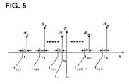
- Fig. 5 shows N path signals, and a plurality of Multi-path Interference Correlative Timings (MICTS) that can be utilized for reduction of interference of a path j contained in a path i .
- MICTS Multi-path Interference Correlative Timings
- S is a desired signal
- I i,j is an interference component by the path j contained in x i .
- a timing t i,j,i is a multi-path interference correlative timing (MICT) used in the previous application.
- the timing t i,j,i is a timing shifted from the timing t i by the time difference ⁇ t between the path i and the path j .
- a signal having a correlation with I i,j can be obtained by inversely spreading at this timing t i,j,i .
- a signal having a correlation with I i,j can be obtained by inversely spreading at a timing t i,j,k ( k is a value from 1 to N except j .) shifted from each of the paths by ⁇ t .
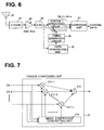
- Fig. 6 shows an example of the construction of a CDMA receiver applied with the present invention.
- a CDMA signal received by an antenna 20 is converted into a base-band signal by a down-converter 21.
- the base-band signal is inputted into an A/D converter 23 through an AGC amplifier 22.
- the base-band signal is converted into a digital signal and is inputted into inverse spreading circuit units 24-1 to 24-n corresponding to the number of paths n and into a path searching unit 25.
- the inverse spreading timings t i,j,k,n are sent respectively to the corresponding inverse spreading circuit units 24-1 to 24-n and inverse spreading processes are executed at the respective timings.
- Inverse spread outputs obtained in the inverse spreading circuit units 24-1 to 24-n are composed in the composing unit 27 and an inverse spread signal is obtained.
- Fig. 7 shows an example of the construction of a composing unit 27 of Fig. 6.
- the construction of an MMSE receiver is shown as an embodiment. Therefore, the composing unit 27 has an MMSE coefficient generating unit 270.
- the MMSE coefficient generating unit 270 obtains composition coefficients that maximizes the S/N of received signals. These coefficients are multiplied as the coefficients to multipliers 271-1 to 271-n respectively corresponding to each of fingers.
- the MMSE coefficient generating unit 270 further comprises an adder 272 that adds the outputs of these multipliers 271-1 to 271-n. Thereby, an output that maximizes the S/N of the received signals can be obtained from the adder 272.
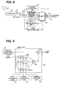
- Fig. 8 shows another exemplary embodiment of the present invention.
- a multi-path interference exchange reduction (MIXR) circuit 28 is provided between the inverse spreading circuit units 24-1 to 24-n and a rake composing unit 27 compared to the exemplary embodiment of the construction of Fig. 6. Interference of each finger is reduced by this multi-path interference exchange reduction (MIXR) circuit 28.
- MIXR multi-path interference exchange reduction
- Fig. 9 shows the detailed construction of the multi-path interference exchange reduction circuit 28. Interference is reduced by reproducing the interference caused by the path j contained in the path i in the MICS units 280-1 to 280-N, adding all outputs of MICS units 280-1 to 280-N in the adder 281 and subtracting the result of the adding from a signal of the path i.
- Each of the above MICS units 280-1 to 280-N reproduces interference entering from the path j to the path i ( j ⁇ i ).
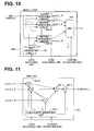
- Fig. 10 shows the details of the MICS units 280-1 to 280-N represented by a MICS unit 280- i .
- timing information t i of a rake path obtained by the path searching unit 25 multi-path interference correlative timings (MICT) t i,j,k are obtained in the timing generating circuit 26i according to the following equation.
- t i,j,k t i -t j + t k ( j ⁇ i )
- a signal mics ( i,j,k ) inversely spread by the respectively corresponding inverse spreading circuits 104-il to 104iN at this obtained timing t i,j,k is obtained and these signals are composed and outputted by an MRC unit 128.
- Fig. 11 shows an example of the construction of the MRC 128.
- the output of the adder 128-3 is multiplied by a coefficient r i , j in an adder 128-4 and the MICS ( i,j ) is obtained. Therefore, the MICS ( i,j ) is represented by the following equation.
- r' k and r i,j are obtained as follows.
- r' k ⁇ k */ ⁇ r ⁇ k
- 2 I 2 + n 2 ⁇ r i,j ⁇ j I 2 / ⁇ ( I / N ) j +1 ⁇
- ( I / N ) j is the ratio of interference to be reproduced and the power of interference other than that and is obtained as follows.
- the coefficient r i is obtained as follows using only the path i as represented in Eq. 3 when the MICS ( i,j ) is obtained.
- the accuracy of the MICS ( i,j ) can be improved and the reduction effect of interference can be improved by composing using paths other than the path i as already shown.
- the coefficient r' k to multiply mics ( i,j,k ) is obtained as follows approximating the noises to be constant when the MICS ( i,j ) is obtained.
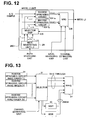
- Fig. 12 shows another example of the construction of the MICS unit 280- i .
- this construction has a selector unit 129 as a characteristic thereof.
- the selector unit 129 determines the magnitude of a path based on a channel estimation value from the channel estimating unit 29 and obtains mics ( i,j,k ) only for large paths. Thereby, the size of the circuitry and the amount to be processed can be reduced without degrading considerably the performance.
- Fig. 13 shows a construction that is provided with a selector circuit 31 at the preceding stage of a MIXR circuit 28, as an exemplary embodiment.
- the selector unit 31 controls such that the magnitude of the path is determined based on the channel estimation value from the channel estimating unit 29 and the MIXR processes are executed only on large paths.
- Fig. 13 is a construction for MIXR-processing two (2) paths and not executing any processes to other (N-2) processes.
- Fig. 14 shows yet another example of the construction of the MICS unit 280-i.
- the inverse spreading timing t i,j,k of the mics ( i,j,k ) may be different from the timing t i of the desired signal.
- t i,j,k may coincide with any one (1) of t i .
- the case where the timing t i,j,k coincides with t i is detected by the timing generating circuit 26 i and the signal of the case of the coincidence is blocked by switches 130-1 to 130-N. Thereby, the degradation of the characteristic can be prevented.
- the timing generating unit 26 i in the exemplary embodiment of Fig. 14 creates the timing t i,j,k to correspond to the above operation and executes comparison with t i . Then, when coincidence or approximation almost equal to coincidence is found, the signal is prevented from being inputted into the MRC unit 128 by controlling accordingly a switch 130- i of an outputting unit of the mics ( i,j,k ) corresponding to the found timing.
- the mics ( i,j,k ) of the timing coinciding with a signal can be masked.
- the noise level of each finger is constant in any finger in the rake composing unit 27 at the following stage of the MIXR unit 28.
- the noise level of each finger containing interference is reduced and dispersion occurs in noise power that was at an almost same level in any finger. Consequently, effect of the rake composition and error correction may not be exerted.
- a level compensating unit 32 between the MIXR unit 28 and the rake composing unit 27 as a construction shown in Fig. 15.
- the noise power can be made same as that before the MIXR process by amplifying appropriately the signal after the MIXR process.
- Fig. 16 shows yet another exemplary embodiment of the present invention. Compared to the exemplary embodiment shown in Fig. 8, the embodiment is characterized in that the positions of the MIXR unit 28 and the inverse spreading circuit unit 24 are exchanged.
- the MICS unit 280- i constituting the MIXR unit 28 has a construction shown in Fig. 17.
- the inverse spreading circuit 104- i is replaced by the delay circuit 105- i .
- the circuit construction can be simplified by arranging the MIXR unit 28 before the inverse spreading circuit unit 24.
- a rake receiver that executes the effective maximal ratio composition in the time domain of signals arriving at an antenna with various differences in delay time thereof caused by multiple reflections of propagation paths of the signals in a multi-path environment.
Landscapes
- Engineering & Computer Science (AREA)
- Computer Networks & Wireless Communication (AREA)
- Signal Processing (AREA)
- Noise Elimination (AREA)
- Mobile Radio Communication Systems (AREA)
Abstract
Description



Claims (11)
- A rake receiver for use in a spread spectrum communication system, comprising:timing detecting unit detecting a reception timing t i (i=1 to N) of each of N paths when direct spread spectrum signals of the N paths are received;inverse spreading timing setting unit setting, as a timing for inverse spreading, a timing t i,j,k (k=1 to N, k≠j) at which an inverse spread value is obtained that has interference and correlation from the jth (j=1 to N, j≠i) path included in the inverse spread value of the ith path counted from the reception timing t i (i=1 to N) detected by the timing detecting ;a plurality of correlators each obtaining an inverse spread signal of the received signal corresponding to each timing set by the inverse spreading timing setting ; andsignal composing unit composing outputs of the plurality of correlators.
- A rake receiver according to claim 1, further comprising:to reproduce interference α j I i,j and subtracting the interference MICS(i,j) from the ith path.between the correlators and the signal composing unit, a circuit composing a multi-path interference signal (mics(i,j,k)) of a path k (k≠j) from the following Eq. (1),

- A rake receiver according to claim 2, wherein, when the multi-path interference signal (mics(i,j,k)) is composed, coefficients r i,j and r' k of Eq. (1) are obtained from the following Eq. (2) and Eq. (3),
- A rake receiver according to claim 2, wherein, when the multi-path interference signal (mics(i,j,k)) is composed, noises of the multi-path interference signal (mics(i,j,k)) are approximated to be constant and the coefficients r i,j and r' k of Eq. (1) are obtained from the following Eq. (4) and Eq. (5),
- A rake receiver according to any one of claims 2 to 4, wherein
the circuit subtracting the interference MICS(i,j) includes a selecting circuit for selecting a plurality of paths having high power, and wherein
the circuit subtracting the interference MICS(i,j) subjects the selected paths to processes for composing the multi-path interference signal (mics(i,j,k)) and subtracting the interference MICS(i,j). - A rake receiver according to claim 2, wherein the circuit subtracting MICS(i,j) from the ith path selects a plurality of paths i having high power and is provided in the quantity corresponding to the number of the selected paths.
- A rake receiver according to any one of claims 2 to 6, wherein
the inverse spreading timing setting unit detect coincidence between the timing t i,j,k for the inverse spreading and a reception timing t i and, do not subject the paths between which the coincidence has been detected, to the processes for composing the multi-path interference signal (mics(i,j,k)) and subtracting the interference MICS(i,j). - A rake receiver according to any one of claims 2 to 6, further comprising:a level compensating circuit disposed between the circuit subtracting the interference MICS(i,j) and the signal composing unit, the level compensating circuit acting to compensate the levels of signals after reduction of the interference in the circuit reducing the interference MICS(i,j) to keep the level of the noises constant.
- A rake receiver according to claim 1, further comprising:at the preceding stage of the correlators, a circuit composing a multi-path interference signal (mics(i,j,k) of a path k (k≠j) from Eq. (1)reproducing interference α j I i,j , and subtracting the interference MICS(i,j) from the ith path.

- A rake receiver according to claim 9, wherein
the circuit subtracting the interference MICS(i,j) includes a circuit selecting a plurality of paths having high power, thereby subjecting the selected paths to the processes for composing the multi-path interference signal (mics(i,j,k)) and subtracting the interference MICS(i,j). - A rake receiver according to claim 9, wherein the circuit subtracting the interference MICS(i,j) from the ith path selects a plurality of paths i having high power and is provided in the quantity corresponding to the number of the selected paths.
Applications Claiming Priority (1)
| Application Number | Priority Date | Filing Date | Title |
|---|---|---|---|
| PCT/JP2002/009414 WO2004025860A1 (en) | 2002-09-13 | 2002-09-13 | Spread spectrum rake receiver |
Publications (3)
| Publication Number | Publication Date |
|---|---|
| EP1548953A1 true EP1548953A1 (en) | 2005-06-29 |
| EP1548953A4 EP1548953A4 (en) | 2006-02-01 |
| EP1548953B1 EP1548953B1 (en) | 2009-08-19 |
Family
ID=31986102
Family Applications (1)
| Application Number | Title | Priority Date | Filing Date |
|---|---|---|---|
| EP02760830A Expired - Lifetime EP1548953B1 (en) | 2002-09-13 | 2002-09-13 | Spread spectrum rake receiver |
Country Status (4)
| Country | Link |
|---|---|
| EP (1) | EP1548953B1 (en) |
| JP (1) | JP3926366B2 (en) |
| DE (1) | DE60233445D1 (en) |
| WO (1) | WO2004025860A1 (en) |
Cited By (2)
| Publication number | Priority date | Publication date | Assignee | Title |
|---|---|---|---|---|
| EP1605602A1 (en) * | 2004-06-11 | 2005-12-14 | Fujitsu Limited | Interference reduction apparatus and method |
| US8265131B2 (en) | 2007-04-20 | 2012-09-11 | Fujitsu Limited | Control apparatus for and control method of equalizer, and wireless terminal having that control apparatus |
Family Cites Families (1)
| Publication number | Priority date | Publication date | Assignee | Title |
|---|---|---|---|---|
| US6865218B1 (en) * | 2000-11-27 | 2005-03-08 | Ericsson Inc. | Multipath interference reduction for a CDMA system |
-
2002
- 2002-09-13 WO PCT/JP2002/009414 patent/WO2004025860A1/en not_active Ceased
- 2002-09-13 EP EP02760830A patent/EP1548953B1/en not_active Expired - Lifetime
- 2002-09-13 JP JP2004535849A patent/JP3926366B2/en not_active Expired - Fee Related
- 2002-09-13 DE DE60233445T patent/DE60233445D1/en not_active Expired - Lifetime
Cited By (4)
| Publication number | Priority date | Publication date | Assignee | Title |
|---|---|---|---|---|
| EP1605602A1 (en) * | 2004-06-11 | 2005-12-14 | Fujitsu Limited | Interference reduction apparatus and method |
| EP1926219A1 (en) * | 2004-06-11 | 2008-05-28 | Fujitsu Limited | Interference reduction apparatus and method |
| US7526012B2 (en) | 2004-06-11 | 2009-04-28 | Fujitsu Limited | Interference reduction apparatus and method |
| US8265131B2 (en) | 2007-04-20 | 2012-09-11 | Fujitsu Limited | Control apparatus for and control method of equalizer, and wireless terminal having that control apparatus |
Also Published As
| Publication number | Publication date |
|---|---|
| DE60233445D1 (en) | 2009-10-01 |
| JPWO2004025860A1 (en) | 2006-01-12 |
| WO2004025860A1 (en) | 2004-03-25 |
| EP1548953A4 (en) | 2006-02-01 |
| JP3926366B2 (en) | 2007-06-06 |
| EP1548953B1 (en) | 2009-08-19 |
Similar Documents
| Publication | Publication Date | Title |
|---|---|---|
| JP3202754B2 (en) | How to handle multiple multiple access transmissions | |
| US6404759B1 (en) | CDMA multi-user receiving apparatus including interference canceller with optimal receiving state | |
| KR100284722B1 (en) | Rake receiver and spread spectrum communication device with this rake receiver | |
| US7397842B2 (en) | Method and apparatus for combining weight computation in a DS-CDMA RAKE receiver | |
| US10153805B2 (en) | Iterative interference suppressor for wireless multiple-access systems with multiple receive antennas | |
| US6614766B1 (en) | Interference canceller | |
| US6526271B1 (en) | Method and apparatus for interference rejection | |
| US8565287B2 (en) | Method and system for per-cell interference estimation for interference suppression | |
| EP0945995A2 (en) | RAKE receiver with adaptive delay profile measurement | |
| EP1605601B1 (en) | Interference eliminating apparatus and method | |
| US8208589B2 (en) | Receiver and reception processing method | |
| US6944208B2 (en) | Interference signal canceling apparatus and interference signal canceling method | |
| EP1605602B1 (en) | Interference reduction apparatus and method | |
| KR20030033192A (en) | Finger Using Mixed Weighting in Smart Antenna System, and Its Application for Demodulation Apparatus and Method | |
| US20040141469A1 (en) | Rake receiver for operating in FDD and TDD modes | |
| US20090257478A1 (en) | Spread spectrum rake receiver | |
| US6233272B1 (en) | Spread spectrum communication receiver | |
| EP1548953B1 (en) | Spread spectrum rake receiver | |
| JP2002077104A (en) | Spread spectrum receiver | |
| EP1030459A2 (en) | CDMA multipath receiver | |
| US7756191B2 (en) | Deconvolution searcher for wireless communication system | |
| JP2001024553A (en) | Interference canceller for CDMA receiver | |
| JP2003324367A (en) | Wireless receiving apparatus and method |
Legal Events
| Date | Code | Title | Description |
|---|---|---|---|
| PUAI | Public reference made under article 153(3) epc to a published international application that has entered the european phase |
Free format text: ORIGINAL CODE: 0009012 |
|
| 17P | Request for examination filed |
Effective date: 20050307 |
|
| AK | Designated contracting states |
Kind code of ref document: A1 Designated state(s): AT BE BG CH CY CZ DE DK EE ES FI FR GB GR IE IT LI LU MC NL PT SE SK TR |
|
| RBV | Designated contracting states (corrected) |
Designated state(s): DE FR GB IT |
|
| A4 | Supplementary search report drawn up and despatched |
Effective date: 20051221 |
|
| GRAP | Despatch of communication of intention to grant a patent |
Free format text: ORIGINAL CODE: EPIDOSNIGR1 |
|
| GRAS | Grant fee paid |
Free format text: ORIGINAL CODE: EPIDOSNIGR3 |
|
| GRAA | (expected) grant |
Free format text: ORIGINAL CODE: 0009210 |
|
| AK | Designated contracting states |
Kind code of ref document: B1 Designated state(s): DE FR GB IT |
|
| REG | Reference to a national code |
Ref country code: GB Ref legal event code: FG4D |
|
| REF | Corresponds to: |
Ref document number: 60233445 Country of ref document: DE Date of ref document: 20091001 Kind code of ref document: P |
|
| PLBE | No opposition filed within time limit |
Free format text: ORIGINAL CODE: 0009261 |
|
| STAA | Information on the status of an ep patent application or granted ep patent |
Free format text: STATUS: NO OPPOSITION FILED WITHIN TIME LIMIT |
|
| 26N | No opposition filed |
Effective date: 20100520 |
|
| REG | Reference to a national code |
Ref country code: FR Ref legal event code: PLFP Year of fee payment: 15 |
|
| REG | Reference to a national code |
Ref country code: FR Ref legal event code: PLFP Year of fee payment: 16 |
|
| REG | Reference to a national code |
Ref country code: FR Ref legal event code: PLFP Year of fee payment: 17 |
|
| PGFP | Annual fee paid to national office [announced via postgrant information from national office to epo] |
Ref country code: IT Payment date: 20180919 Year of fee payment: 17 Ref country code: FR Payment date: 20180813 Year of fee payment: 17 Ref country code: DE Payment date: 20180828 Year of fee payment: 17 |
|
| PGFP | Annual fee paid to national office [announced via postgrant information from national office to epo] |
Ref country code: GB Payment date: 20180912 Year of fee payment: 17 |
|
| REG | Reference to a national code |
Ref country code: DE Ref legal event code: R119 Ref document number: 60233445 Country of ref document: DE |
|
| PG25 | Lapsed in a contracting state [announced via postgrant information from national office to epo] |
Ref country code: DE Free format text: LAPSE BECAUSE OF NON-PAYMENT OF DUE FEES Effective date: 20200401 |
|
| PG25 | Lapsed in a contracting state [announced via postgrant information from national office to epo] |
Ref country code: IT Free format text: LAPSE BECAUSE OF NON-PAYMENT OF DUE FEES Effective date: 20190913 |
|
| GBPC | Gb: european patent ceased through non-payment of renewal fee |
Effective date: 20190913 |
|
| PG25 | Lapsed in a contracting state [announced via postgrant information from national office to epo] |
Ref country code: FR Free format text: LAPSE BECAUSE OF NON-PAYMENT OF DUE FEES Effective date: 20190930 Ref country code: GB Free format text: LAPSE BECAUSE OF NON-PAYMENT OF DUE FEES Effective date: 20190913 |