EP1548940A1 - Abtastratenumsetzer - Google Patents
Abtastratenumsetzer Download PDFInfo
- Publication number
- EP1548940A1 EP1548940A1 EP03029325A EP03029325A EP1548940A1 EP 1548940 A1 EP1548940 A1 EP 1548940A1 EP 03029325 A EP03029325 A EP 03029325A EP 03029325 A EP03029325 A EP 03029325A EP 1548940 A1 EP1548940 A1 EP 1548940A1
- Authority
- EP
- European Patent Office
- Prior art keywords
- sample rate
- filter
- phase
- digital
- zero
- Prior art date
- Legal status (The legal status is an assumption and is not a legal conclusion. Google has not performed a legal analysis and makes no representation as to the accuracy of the status listed.)
- Ceased
Links
- 230000004044 response Effects 0.000 claims description 54
- 238000012546 transfer Methods 0.000 claims description 16
- 230000000063 preceeding effect Effects 0.000 claims 3
- 230000001364 causal effect Effects 0.000 description 36
- 238000000034 method Methods 0.000 description 18
- 238000001914 filtration Methods 0.000 description 17
- 230000006870 function Effects 0.000 description 16
- 238000012545 processing Methods 0.000 description 13
- 238000013461 design Methods 0.000 description 11
- 239000000872 buffer Substances 0.000 description 6
- 230000011218 segmentation Effects 0.000 description 6
- 230000001052 transient effect Effects 0.000 description 5
- 238000005457 optimization Methods 0.000 description 4
- 230000007423 decrease Effects 0.000 description 3
- 230000008569 process Effects 0.000 description 3
- 230000002441 reversible effect Effects 0.000 description 3
- 230000001934 delay Effects 0.000 description 2
- 230000003111 delayed effect Effects 0.000 description 2
- 230000000694 effects Effects 0.000 description 2
- 238000012986 modification Methods 0.000 description 2
- 230000004048 modification Effects 0.000 description 2
- 238000011144 upstream manufacturing Methods 0.000 description 2
- 230000002411 adverse Effects 0.000 description 1
- 230000000593 degrading effect Effects 0.000 description 1
- 230000010363 phase shift Effects 0.000 description 1
- 230000005236 sound signal Effects 0.000 description 1
Images



Classifications
-
- H—ELECTRICITY
- H03—ELECTRONIC CIRCUITRY
- H03H—IMPEDANCE NETWORKS, e.g. RESONANT CIRCUITS; RESONATORS
- H03H17/00—Networks using digital techniques
- H03H17/02—Frequency selective networks
- H03H17/04—Recursive filters
- H03H17/0416—Recursive filters with input-sampling frequency and output-delivery frequency which differ, e.g. extrapolation; Anti-aliasing
-
- H—ELECTRICITY
- H03—ELECTRONIC CIRCUITRY
- H03H—IMPEDANCE NETWORKS, e.g. RESONANT CIRCUITS; RESONATORS
- H03H17/00—Networks using digital techniques
- H03H17/02—Frequency selective networks
- H03H17/0283—Filters characterised by the filter structure
- H03H17/0286—Combinations of filter structures
- H03H17/0288—Recursive, non-recursive, ladder, lattice structures
Definitions
- the invention relates to sample rate converter for converting a digital input signal having a first sample rate into a digital output signal having a second sample rate, wherein the second sample rate is different from the first sample rate.
- DVDs Digital Video Discs
- MP3 audio files may have a sample rate of 8 kHz, 16 kHz, or 32 kHz and audio signals transmitted by a MOST bus may have a 44,1 kHz sample rate.
- sample rate converters are used converting these varying sample rates into a rate adequate for further processing.
- a common sample rate converter 10 for converting a digital input signal 11 having a first sample rate f s1 into a digital output signal 15 having a second sample rate f S2 different from the first sample rate f S1 basically comprises a digital interpolation filter 12 receiving the input signal 11 and a digital polynom interpolator 14 connected to the interpolation filter 12 for transmitting an intermediate signal 13, and providing the output signal 15.
- R. Adams and T. Kwan disclose in "Theory and VLSI Architectures for Asynchronous Sample-Rate Converters", J. Aud. Eng. Soc. Vol. 41, No. 7/8, 1993 July/August, p.539-555 different types of sample rate converters using different interpolation filters.
- the converters disclosed therein have in common that they either require a lot of memory space and/or a large processor capacity, or showing some instabilities or major phase nonlinearities.
- FIR Finite Impulse Response
- IIR Infinite Impulse Response
- the inventive sample rate converter for converting a digital input signal having a first sample rate comprises, beside a digital polynom interpolator providing the output signal with a second sample rate, a digital interpolation filter receiving the input signal and being connected upstream of the interpolation filter, wherein the interpolation filter comprises a digital zero-phase filter.
- the zero-phase filter 20 receiving an input signal 11 with a sample rate fs1 and providing an output signal with a sample rate fs2, comprises two identical IIR filters 22, 24 having a transfer function H c (f) wherein the IIR filter 24 is connected to the IIR filter 22 via a signal time reverser 23.
- the transfer function of a zero phase IIR filter derived from a stable causal filter, has poles inside and outside the unit circle. Its zeros may appear also on the unit circle.
- the poles inside the unit circle belong to H c (z), those outside the unit circle to H nc (z).
- the order of the noncausal filter H(z) is twice the order of the causal filter H c (z).
- the transfer function i. e. the overall frequency response of the noncausal filter H(z) is as described in equation (1). As shown, the overall frequency response is a real function of frequency.
- the filter having a transfer function H(z) has a phase response equal to zero which means, on one hand, that this filter creates absolutely no phase distortions and no group delay but, on the other hand, that it is a noncausal system and, therefore, cannot be realized in real time.
- Noncausal systems react, by definition, to an input signal in advance, that is before the stimulus is effective. Obviously, such systems are not realizable in real time, i. e. on-line filtering is not possible. However, they can be well applied to signals which have been recorded into a storage medium, i. e. off-line filtering.
- the parallel structure is superior to the cascaded one with respect to implementation complexity. But in case the zero phase filtering concept is employed to realize linear-phase IIR filters in real time, the cascaded structure is preferred. Therefore, in the following the implementation will be focused to the cascaded structure wherein a noncausal filter is followed by a causal one, since this scheme will be applied later to realize linear-phase IIR filters. Further, it is assumed, that the input signal (sequence) is saved in a storage medium and can be sequentially read from there, wherein the subfilters are IIR filters.
- a causal filter H c (z), h c (n)
- the filtering operation e. g. difference equation or convolution
- H nc (z) H c (z -1 )
- h nc (n) h c (-n)
- the filtering operation is applied in the reversed direction. It starts from the last sample of the input sequence, continuing backward to its previous samples (backward or reversed order filtering).
- a noncausal filter maybe implemented by the following steps:
- H c (z) and h c (n) represent two identical causal IIR filters (first pass and second pass subfilter).
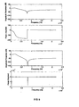
- FIG. 5a shows the amplitude and phase response of a biquad filter
- Figure 5b the magnitude and phase response of a zero phase IIR filter employing the biquad filter as its subfilters.
- the overall phase response of the system is identically equal zero, its overall magnitude response is, according to equation (1), equal to the square of the magnitude response of the causal IIR subfilter H c (z) .
- the frequency response of a zero phase IIR filter is equal to the square of the magnitude response of its causal IIR subfilter. Therefore, the design of a zero phase IIR filter can be redefined as a design problem for a causal IIR filter:
- zero phase IIR filters can be designed by using an optimization design method applicable to this type of filters.
- a multiple criterion optimization design technique maybe applied to design noncausal filters of general type including zero phase IIR filters. This design method accepts simultaneous constraints with respect to magnitude response and group delay.
- the design procedure computes the transfer function of the desired zero phase filter H (z).
- the required causal subfilter H c (z) can be obtained by combining the poles and zeros of H(z) locating inside the unit circle.
- vr k (n) v k (-n).
- the desired output sequence of the noncausal subfilter is obtained by superimposing the section responses vr k (n) in a proper way as described next. To find out the adequate way of combining the section responses, the following points should be taken into account:
- the design and implementation procedure for a linear-phase IIR filter based on the above mentioned points consists of the steps of designing a causal subfilter H c (z), the squared magnitude response of which fulfils given specifications (see previous section); and computing the impulse response h c (n) of the subfilter and estimating the critical section length L c .
- the Implementation scheme may be as follows:
- the implementation scheme demands at least two double buffers of L c samples length for the input and the output section, and one buffer of 2L c samples length for the intermediate sequence v k (n).
- the algorithm generates a delay of L c samples between the input and the output sequence, and, ideally a constant group delay of L c /2 samples.
- H(z) H c (z -1 )H c (z) z -L/2
- Figure 6 illustrates the frequency responses of a causal biquad filter and of a fourth order linear-phase IIR filter using the biquad filter as its subfilters.
- a zero phase filter consists of two cascaded filters (subfilters): a noncausal subfilter and a causal subfilter.
- the noncausal subfilter is implemented by utilizing a causal filter identical to the second causal filter in this way:
- the input signal is first time reversed in whole length, then passed through a causal filter(H c (z), h c (n)).
- the response of this filter is time reversed and passed through the second causal filter (H c (z), h c (n)) to obtain the desired output signal.
- the time reversing of the intermediate response brings about the following implication: Since the input signal is time limited, the intermediate response exhibits a final transient part following its initial transient and steady state part. In case of an IIR subfilter the final transient part decays more or less quickly towards zero but, theoretically it never reaches zero. Therefore, it must be truncated at a certain time instant, before it is time reversed. To properly take account of the final transient part, the duration of the truncated intermediate response must be sufficiently longer than the duration of the input signal.
- the input signal is assumed to be practically unlimited in time. As a consequence it cannot be time reversed entirely in one step as required by the zero phase filtering concept. Nevertheless, the concept can be modified for real time implementation as indicated in Figure 4.
- the continuous input signal 41 is segmented in a section unit 42 and recorded into blocks of L samples, and the zero-phase filtering concept is then applied to the individual recorded sections by a time reverser 43, a causal subfilter 44, and a time reverse 45 with a subsequent causal subfilter 47 provide an output signal 48.
- the block processing brings about a delay equal to or larger than the segment duration.
- the noncausal subfilter demanded by the zero phase filtering concept can be conceived in this case as a "delayed noncausal subfilter 40" which is actually a causal one and therefore realizable in real time.
- the subfilters 40, 47 used by the zero-phase concept are IIR filters, the application of this concept to the individual sections inevitably causes truncation errors which more or less deteriorate the overall filter performance.
- the linear phase filtering algorithm may be described as a sequence of the following steps:
- Truncating the intermediate responses forces the filter output signal to deviate from its ideal form which would be obtained without the truncation step.
- Said sample rate converter comprises a section unit 72 receiving an input signal 71 with a sample rate f s1 .
- a zero-phase filter 73 is connected upstream to the section unit 72 providing an intermediate signal 74 with a sample rate f s3 .
- the intermediate signal 74 is fed into a polynom interpolator 75 connected to the zero-phase filter 73.
- a combination unit 76 is connected to the polynom interpolator 75 and provides an output signal 77 having a sample rate f S2 .
- the sample rate f s2 is different from the sample rate f S1 , wherein the sample rate f s3 is higher than either the sample rate f S1 and sample rate f S2 .
- the above-mentioned systems may be implemented in microprocessors, signal processors, microcontrollers, computing devices etc.
- the individual system components are in this case hardware components of the microprocessors, signal processors, microcontrollers, computing devices, etc. which are correspondingly implemented by means of software.
Landscapes
- Physics & Mathematics (AREA)
- Engineering & Computer Science (AREA)
- Computer Hardware Design (AREA)
- Mathematical Physics (AREA)
- Complex Calculations (AREA)
Priority Applications (2)
| Application Number | Priority Date | Filing Date | Title |
|---|---|---|---|
| EP03029325A EP1548940A1 (de) | 2003-12-18 | 2003-12-18 | Abtastratenumsetzer |
| US11/017,021 US7167113B2 (en) | 2003-12-18 | 2004-12-20 | Sample rate converter having a zero-phase filter |
Applications Claiming Priority (1)
| Application Number | Priority Date | Filing Date | Title |
|---|---|---|---|
| EP03029325A EP1548940A1 (de) | 2003-12-18 | 2003-12-18 | Abtastratenumsetzer |
Publications (1)
| Publication Number | Publication Date |
|---|---|
| EP1548940A1 true EP1548940A1 (de) | 2005-06-29 |
Family
ID=34530680
Family Applications (1)
| Application Number | Title | Priority Date | Filing Date |
|---|---|---|---|
| EP03029325A Ceased EP1548940A1 (de) | 2003-12-18 | 2003-12-18 | Abtastratenumsetzer |
Country Status (2)
| Country | Link |
|---|---|
| US (1) | US7167113B2 (de) |
| EP (1) | EP1548940A1 (de) |
Cited By (1)
| Publication number | Priority date | Publication date | Assignee | Title |
|---|---|---|---|---|
| US11610597B2 (en) | 2020-05-29 | 2023-03-21 | Shure Acquisition Holdings, Inc. | Anti-causal filter for audio signal processing |
Families Citing this family (4)
| Publication number | Priority date | Publication date | Assignee | Title |
|---|---|---|---|---|
| US7450036B2 (en) * | 2004-12-20 | 2008-11-11 | Harman Becker Automotive Systems Gmbh | Sample rate converter having a zero-phase filter |
| US7283076B1 (en) * | 2006-06-29 | 2007-10-16 | Cirrus Logic, Inc. | Digital non-integer sample/hold implemented using virtual filtering |
| MX361826B (es) * | 2014-01-30 | 2018-12-18 | Huawei Tech Co Ltd | Sistema de compresion de audio para comprimir una señal de audio. |
| CN110601678B (zh) * | 2019-08-31 | 2023-09-29 | 惠州市德赛西威智能交通技术研究院有限公司 | 一种iir滤波器实现零相位的方法及其装置 |
Citations (1)
| Publication number | Priority date | Publication date | Assignee | Title |
|---|---|---|---|---|
| WO1999060940A1 (en) * | 1998-05-28 | 1999-12-02 | Glenayre Electronics, Inc. | Forward-backward channel interpolator |
Family Cites Families (3)
| Publication number | Priority date | Publication date | Assignee | Title |
|---|---|---|---|---|
| US4750180A (en) * | 1986-07-24 | 1988-06-07 | Western Atlas International, Inc. | Error correcting method for a digital time series |
| JP3255179B2 (ja) * | 1992-02-14 | 2002-02-12 | ソニー株式会社 | データ検出装置 |
| US6591283B1 (en) * | 1998-12-24 | 2003-07-08 | Stmicroelectronics N.V. | Efficient interpolator for high speed timing recovery |
-
2003
- 2003-12-18 EP EP03029325A patent/EP1548940A1/de not_active Ceased
-
2004
- 2004-12-20 US US11/017,021 patent/US7167113B2/en not_active Expired - Fee Related
Patent Citations (1)
| Publication number | Priority date | Publication date | Assignee | Title |
|---|---|---|---|---|
| WO1999060940A1 (en) * | 1998-05-28 | 1999-12-02 | Glenayre Electronics, Inc. | Forward-backward channel interpolator |
Non-Patent Citations (5)
| Title |
|---|
| ADAMS R ET AL: "THEORY AND VLSI ARCHITECTURES FOR ASYNCHRONOUS SAMPLE-RATE CONVERTERS", JOURNAL OF THE AUDIO ENGINEERING SOCIETY, AUDIO ENGINEERING SOCIETY. NEW YORK, US, vol. 41, no. 7/8, July 1993 (1993-07-01), pages 539 - 555, XP009025807, ISSN: 0004-7554 * |
| JOHN G. PROAKIS, DIMITRIS G. MANOLAKIS: "Digital Signal Processing: principles, algorithms, and applications", 1996, PRENTICE-HALL, UPPER SADDLE RIVER, NJ, USA, XP002280182 * |
| P.P.VAIDYANATHAN: "Multirate Systems and Filter Banks", 1993, PRENTICE-HALL, UPPER SADDLE RIVER, NJ, USA, XP002280183 * |
| POWELL S.R.; CHAU P.M.: "A Technique for Realising Linear Phase IIR Filters", IEEE TRANSACTIONS ON SIGNAL PROCESSING, vol. 39, no. 11, 1 November 1991 (1991-11-01), NEW YORK, NY, USA, pages 2425 - 2435, XP000271452 * |
| RAMSTAD T A: "DIGITAL METHODS FOR CONVERSION BETWEEN ARBITRARY SAMPLING FREQUENCIES", IEEE TRANSACTIONS ON ACOUSTICS, SPEECH AND SIGNAL PROCESSING, IEEE INC. NEW YORK, US, vol. ASSP-32, no. 3, 1 June 1984 (1984-06-01), pages 577 - 591, XP002025612, ISSN: 0096-3518 * |
Cited By (1)
| Publication number | Priority date | Publication date | Assignee | Title |
|---|---|---|---|---|
| US11610597B2 (en) | 2020-05-29 | 2023-03-21 | Shure Acquisition Holdings, Inc. | Anti-causal filter for audio signal processing |
Also Published As
| Publication number | Publication date |
|---|---|
| US20050168361A1 (en) | 2005-08-04 |
| US7167113B2 (en) | 2007-01-23 |
Similar Documents
| Publication | Publication Date | Title |
|---|---|---|
| US6487573B1 (en) | Multi-rate digital filter for audio sample-rate conversion | |
| US6854002B2 (en) | Efficient interpolator for high speed timing recovery | |
| Jiang et al. | Efficient digital filtering architectures using pipelining/interleaving | |
| US7450036B2 (en) | Sample rate converter having a zero-phase filter | |
| WO1996037953A1 (en) | Multi-rate iir decimation and interpolation filters | |
| US7010557B2 (en) | Low power decimation system and method of deriving same | |
| US5835390A (en) | Merged multi-stage comb filter with reduced operational requirements | |
| JP4326031B2 (ja) | 帯域合成フィルタバンク及びフィルタリング方法並びに復号化装置 | |
| Kahles et al. | Oversampling for nonlinear waveshaping: Choosing the right filters | |
| US7102547B2 (en) | Method of near-unity fractional sampling rate alteration for high fidelity digital audio | |
| US7167113B2 (en) | Sample rate converter having a zero-phase filter | |
| EP0388958A2 (de) | Verstärkungs-/Phase-Ausgleichsschaltung für ein Servoregelungssystem in einem optischen Plattengerät | |
| US7492848B2 (en) | Method and apparatus for efficient multi-stage FIR filters | |
| US8725785B1 (en) | Parallel infinite impulse response filter | |
| US20050171989A1 (en) | Digital filter design method and device, digital filter design program, and digital filter | |
| US6639535B1 (en) | Digital to analog converter using B spline function | |
| Russell et al. | Efficient arbitrary sampling rate conversion with recursive calculation of coefficients | |
| US7225213B2 (en) | Interpolation filter and method for digitally interpolating a digital signal | |
| JP2008021119A (ja) | デジタルフィルタおよびこれを用いた画像処理装置 | |
| KR100252567B1 (ko) | 수정된영상신호를발생시키는방법 | |
| US7292630B2 (en) | Limit-cycle-free FIR/IIR halfband digital filter with shared registers for high-speed sigma-delta A/D and D/A converters | |
| US6772022B1 (en) | Methods and apparatus for providing sample rate conversion between CD and DAT | |
| EP1557946A1 (de) | Entwurfsverfahren und einrichtung f r digitale filter, entwurfsprogramm f r digitale filter und digitales filter | |
| US7177812B1 (en) | Universal sampling rate converter for digital audio frequencies | |
| WO2002101925A1 (fr) | Dispositif d'interpolation de donnees et procede correspondant, dispositif de generation de fonctions d'echantillonnage, programme d'interpolation de donnees, et support enregistre |
Legal Events
| Date | Code | Title | Description |
|---|---|---|---|
| PUAI | Public reference made under article 153(3) epc to a published international application that has entered the european phase |
Free format text: ORIGINAL CODE: 0009012 |
|
| 17P | Request for examination filed |
Effective date: 20040828 |
|
| AK | Designated contracting states |
Kind code of ref document: A1 Designated state(s): AT BE BG CH CY CZ DE DK EE ES FI FR GB GR HU IE IT LI LU MC NL PT RO SE SI SK TR |
|
| AX | Request for extension of the european patent |
Extension state: AL LT LV MK |
|
| AKX | Designation fees paid |
Designated state(s): AT BE BG CH CY CZ DE DK EE ES FI FR GB GR HU IE IT LI LU MC NL PT RO SE SI SK TR |
|
| STAA | Information on the status of an ep patent application or granted ep patent |
Free format text: STATUS: THE APPLICATION HAS BEEN REFUSED |
|
| 18R | Application refused |
Effective date: 20071102 |