EP1548919A2 - Electric generator having a magnetohydrodynamic effect - Google Patents
Electric generator having a magnetohydrodynamic effect Download PDFInfo
- Publication number
- EP1548919A2 EP1548919A2 EP04028552A EP04028552A EP1548919A2 EP 1548919 A2 EP1548919 A2 EP 1548919A2 EP 04028552 A EP04028552 A EP 04028552A EP 04028552 A EP04028552 A EP 04028552A EP 1548919 A2 EP1548919 A2 EP 1548919A2
- Authority
- EP
- European Patent Office
- Prior art keywords
- solution
- circuit
- hydraulic circuit
- electric generator
- length
- Prior art date
- Legal status (The legal status is an assumption and is not a legal conclusion. Google has not performed a legal analysis and makes no representation as to the accuracy of the status listed.)
- Withdrawn
Links
Images

Classifications
-
- H—ELECTRICITY
- H02—GENERATION; CONVERSION OR DISTRIBUTION OF ELECTRIC POWER
- H02K—DYNAMO-ELECTRIC MACHINES
- H02K44/00—Machines in which the dynamo-electric interaction between a plasma or flow of conductive liquid or of fluid-borne conductive or magnetic particles and a coil system or magnetic field converts energy of mass flow into electrical energy or vice versa
- H02K44/08—Magnetohydrodynamic [MHD] generators
- H02K44/085—Magnetohydrodynamic [MHD] generators with conducting liquids
Definitions
- This invention relates to an electric generator, and in particular an electric generator based on the magnetohydrodynamic effect.
- the object of the invention in particular is to provide an electric generator of high efficiency and small dimensions.
- the said at least one source of pressurized gas comprises a microcombustor device.
- the vehicle liquid for the colloidal solution may for example be water or an alcohol, and the metal material dispersed in it may comprise micro- or nanoparticles of one or more noble metals, of one or more alkali metals, or again mercury or alloys of tin and zinc.
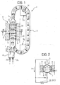
- an electric generator according to the invention is indicated as a whole by 1.
- This generator comprises a pressurized-gas source 2, comprising for example a microcombustor, with an inlet 2a for a fuel and an inlet 2b for a comburent or oxidizing agent.
- Outlet 2c for the exhaust gases for a microcombustor 2 is in the form of a nozzle and is connected to a port or inlet connection 3a to a hydraulic circuit indicated as a whole by 3.
- This comprises variable-density ceramic material with a greater density on the inside gradually reducing towards the outside and capable of rendering the structure adiabatic in order to minimize radiation losses.
- This circuit essentially comprises a conduit which is closed upon itself in the form of a ring filled with a colloidal solution which comprises an electrically conducting vehicle liquid such as water or an alcohol in which a charge of micro- or nanoparticles of a metal material, for example one or more noble metals, or one or more alkali metals, or again mercury, or alloys of tin and zinc are dispersed.
- a colloidal solution which comprises an electrically conducting vehicle liquid such as water or an alcohol in which a charge of micro- or nanoparticles of a metal material, for example one or more noble metals, or one or more alkali metals, or again mercury, or alloys of tin and zinc are dispersed.
- Inlet port 3a to hydraulic circuit 3 is constructed and orientated in such a way that, when in operation, it can allow a flow of gas, shown symbolically by an arrow indicated by 4, into the circuit in a direction substantially parallel to the local flow direction of the aforesaid solution.
- the flow of high-pressure gas thus entering circuit 3 is capable of inducing circulation of the said solution in a predetermined direction forming a two-phase gas-liquid mixture with it.
- this solution circulates clockwise, as shown symbolically by a plurality of arrows.
- a choke 5 that is a restriction in cross section transverse to the flow, calibrated so as to cause a predetermined increase in velocity and condensation of the aforesaid two-phase gas-liquid mixture, is provided in hydraulic circuit 3 downstream from inlet port 3a.
- hydraulic circuit 3 shown in Figure 1 may have dimensions of the order of 3 x 5 cm, a cross section with a diameter of the order of 0.5 cm, which reduces to approximately 0.1 cm at choke 5.
- hydraulic circuit 3 Downstream from choke 5, hydraulic circuit 3 has an outlet port, indicated as a whole by 3b, through which gases mixed with the circulating solution may be released and evacuated from the circuit.
- hydraulic circuit 3 At this outlet port 3b, hydraulic circuit 3 has a portion of porous wall 3c which will selectively permit escape of the gases alone.
- the porosity is selected in such a way that the metallic liquid with a high surface tension cannot penetrate away from the combustion circuit.
- the portion of porous wall 3c is conveniently provided on the inside of inner circuit 3b. This also makes it possible to guarantee the continuity and direction of the solution's flow.
- Outlet port 3b is preferably located in the position illustrated by a solid line in Figure 1, but this may also be located elsewhere, between choke 5 and inlet port 3a, for example in the location shown by a dashed line.
- the length of the circuit lying between inlet port 3a and choke 5, indicated by 6 in Figure 1, is preferably straight.
- This length 6 of hydraulic circuit 3 is associated with a magnetic-field-generating arrangement 7 which in the embodiment illustrated by way of example comprises two magnetic poles 8 and 9 of opposite polarity (North and South) arranged facing each other on opposite sides of the said length of circuit. These poles may be the poles of a permanent magnet.
- Magnetic-field-generating arrangement 7 is provided in such a way as to generate a magnetic induction flux whose lines of force extend substantially along a direction at right angles to the flow direction of the solution in length 6 of hydraulic circuit 3. These lines of force are indicated by 10 in Figure 1.
- the magnetic-field-generating arrangement 7 may comprise one or more electromagnets, or a permanently magnetic coating directly applied to length 6 of hydraulic circuit 3.
- Electrodes 12 and 13 indicate two electrodes placed in contact with the solution flowing in length 6 of hydraulic circuit 3. Electrodes 12 and 13 are positioned opposite each other in a direction essentially at right angles to the lines of force 10 of the magnetic field produced by magnetic poles 8 and 9 and the flow direction of the solution in that length of circuit 6.
- the internal resistance R1 of generator 1 depends on the conductivity of the solution flowing in hydraulic circuit 3, and the geometry of the system.
- the colloidal solution used must be prepared in a way which is also optimal from the point of view of properties such as viscosity, for the purposes of fluid-dynamic yield.
- FIG. 2 illustrates a variant embodiment of an electric generator according to the invention.
- parts and components which are identical to or correspond to components already described are again attributed the same reference numbers as used previously.
- hydraulic circuit 3 has a plurality of inlet ports 3a which receive corresponding flows of pressurized gas from corresponding sources 2, such as microcombustors. Each of these inlet ports 3a is followed in the operating direction of the solution flow defined above by a corresponding restriction in cross section 5 and then a corresponding outlet port 3b. Between each restriction 5 and subsequent outlet port 3b, the hydraulic circuit has a corresponding supplementary inlet port 3'a, operatively connected to an associated pressurized gas source 2', such as a microcombustor.
- a corresponding magnetic-field-generating arrangement 7 is associated with each of the preferably straight lengths 6 of hydraulic circuit 3 lying between each inlet port 3a and the subsequent restriction in cross section 5, and between each supplementary inlet port 3'a and the subsequent outlet port 3b.
- each associated with a single length 6 of hydraulic circuit 3 it is possible when in operation to draw off an electric current which can be transferred to a user device.
- the pairs of electrodes associated with the various straight lengths of hydraulic circuit 3 may be interconnected with each other in various ways, for example in series or in parallel.
Landscapes
- Physics & Mathematics (AREA)
- Fluid Mechanics (AREA)
- Engineering & Computer Science (AREA)
- Power Engineering (AREA)
- Physical Or Chemical Processes And Apparatus (AREA)
- Soft Magnetic Materials (AREA)
Abstract
at least one inlet port (3a; 3'a) connected to the source (2; 2') so that, when in operation, it receives a flow of pressurized gas capable of causing circulation of the solution within the circuit (3) in a predetermined direction, forming a two-phase gas-liquid mixture with it,
a restriction in cross section (5), downstream from the inlet port (3a) calibrated in such a way as to cause an increase in velocity and condensation of the two-phase mixture, and
at least one outlet port (3b), located downstream from the restriction (5) through which the gas mixed with the solution can be released and discharged from the circuit (3).
- at least one pair of electrodes (12, 13) placed in contact with the solution in that length (6) of the hydraulic circuit (3), and facing each other in a direction essentially at right angles to the lines of force (10) of the magnetic field and the flow direction of the solution in that length of circuit (6).
Description
- at least one source of pressurized gas,
- a closed hydraulic circuit, essentially in the shape of a ring, containing a colloidal solution comprising an electrically conducting vehicle liquid in which a charge of micro- or nanoparticles of a metal material is dispersed; the hydraulic circuit having
a restriction in the flow cross section located downstream from the said inlet port and calibrated so as to cause an increase in velocity and condensation of the said two-phase mixture, and
at least one outlet port located downstream from the restriction through which the gas mixed with the said solution can be released and evacuated from the circuit;
the generator also comprising
- magnetic field generating means associated with a length of the hydraulic circuit lying between the said inlet port and the restriction in cross section and capable of generating an induction flux substantially at right angles to the flow direction of the solution in that length of circuit, and
- at least one pair of electrodes placed in contact with the solution in that length of the hydraulic circuit, facing each other in a direction essentially at right angles to the lines of force of the magnetic field produced by the said generator means and the flow direction of the solution in that length of circuit,
Claims (12)
- Electric generator (2) comprisingat least one source of pressurized gas (2; 2'),a closed hydraulic circuit (3), essentially in the form of a ring, containing a solution comprising an electrically-conducting vehicle liquid in which a charge of micro- or nanoparticles of a metal material is dispersed; the hydraulic circuit (3) having
at least one inlet port (3a; 3'a) connected to the said source (2; 2') so that, when in operation, it receives a flow of pressurized gas capable of causing circulation of the said solution within the circuit (3) in a predetermined direction, forming a two-phase gas-liquid mixture with it,
a restriction (5) in the flow cross section, located downstream of the said inlet port (3a) and calibrated so as to cause an increase in velocity and condensation of the said two-phase mixture, and
at least one outlet port (3b) located downstream from the said restriction (5) through which gas mixed with the said solution can be released and evacuated from the circuit (3),magnetic-field-generating means (7; 8, 9) associated with a length (6) of the hydraulic circuit (3) lying between the inlet port (3a) and the restriction in cross section (5) capable of generating an induction flux (10) substantially at right angles to the direction of flow of the solution in the said length of circuit (6), andat least one pair of electrodes (12, 13) placed in contact with the solution in that length (6) of the hydraulic circuit (3) and facing each other in a direction essentially at right angles to the lines of force (10) of the magnetic field produced by the said generating means (7; 8, 9) and the flow direction of the solution in the said length of circuit (6),
the arrangement being such that, when in operation, an electric current (I) whose strength depends on the flow velocity (v) of the solution in the said length (6) of the hydraulic circuit (3), the strength of the associated magnetic field (B) and the electrical resistance (R1) between the aforesaid electrodes (12, 13), flows between the said electrodes (12, 13). - Electric generator according to Claim 1, in which the said at least one source of pressurized gas comprises a microcombustion device (2, 2').
- Electric generator according to Claim 1 or 2, in which the inlet port (3a) is constructed in such a way that a flow of gas (4) can be delivered through it into the circuit (3) in a direction substantially parallel to the local flow direction of the aforesaid solution.
- Electric generator according to any of the preceding claims, in which the said outlet port (3b) comprises a portion of porous wall (3c) of the hydraulic circuit (3) capable of permitting gas to escape from the circuit (3).
- Electric generator according to Claim 4, in which the said portion of porous wall (3c) is located on the inside of the circuit (3).
- Electric generator according to any of the preceding claims, comprising a hydraulic circuit (3) having a plurality of inlet ports (3a) designed to receive flows of pressurized gas respectively and each of which is followed in the operating direction of the solution flow by a corresponding restriction in cross section (5) and then a corresponding outlet port (3b), and in which the hydraulic circuit (3) has a corresponding supplementary inlet port (3'a) which can be operatively connected to a corresponding pressurized gas source (2') between each restriction (5) and the subsequent outlet port (3b).
- Electric generator according to Claim 6, in which magnetic-field-generating means (7) are associated with the lengths (6) of hydraulic circuit (3) lying between each inlet port (3a) and the subsequent restriction in cross section (5), and between each supplementary inlet port (3'a) and the subsequent outlet port (3b).
- Electric generator according to any of the preceding claims, in which the or each length (6) of the hydraulic circuit (3) with which magnetic-field-generating means (7; 8, 9) are associated is substantially straight.
- Electric generator according to any of the preceding claims, in which the vehicle liquid is water or an alcohol.
- Electric generator according to any of the preceding claims, in which the said metal material comprises micro- or nanoparticles of one or more noble metals or one or more alkali metals.
- Electric generator according to any of Claims 1 to 9, in which the metal material comprises micro- or nanoparticles of mercury.
- Electric generator according to any of Claims 1 to 9, in which the said metal material comprises micro- or nanoparticles of alloys of tin and zinc.
Applications Claiming Priority (2)
| Application Number | Priority Date | Filing Date | Title |
|---|---|---|---|
| IT001022A ITTO20031022A1 (en) | 2003-12-18 | 2003-12-18 | ELECTRIC MAGNETOIDRODINAMIC EFFECT GENERATOR. |
| ITTO20031022 | 2003-12-18 |
Publications (2)
| Publication Number | Publication Date |
|---|---|
| EP1548919A2 true EP1548919A2 (en) | 2005-06-29 |
| EP1548919A3 EP1548919A3 (en) | 2006-11-29 |
Family
ID=34531942
Family Applications (1)
| Application Number | Title | Priority Date | Filing Date |
|---|---|---|---|
| EP04028552A Withdrawn EP1548919A3 (en) | 2003-12-18 | 2004-12-02 | Electric generator having a magnetohydrodynamic effect |
Country Status (5)
| Country | Link |
|---|---|
| US (1) | US7061129B2 (en) |
| EP (1) | EP1548919A3 (en) |
| JP (1) | JP2005185096A (en) |
| CN (1) | CN1649244A (en) |
| IT (1) | ITTO20031022A1 (en) |
Cited By (3)
| Publication number | Priority date | Publication date | Assignee | Title |
|---|---|---|---|---|
| FR2955199A1 (en) * | 2010-01-14 | 2011-07-15 | Radoslav Iliev Ionov | Method for directly converting mechanical energy e.g. kinematic energy, into electromagnetic energy and vice versa, in e.g. power stations, involves performing mechanical work by extraction or introduction of electromagnetic energy |
| WO2011148188A1 (en) * | 2010-05-27 | 2011-12-01 | Green Energy Incorporated Limited | Improvements in and relating to pumps |
| NL2013504B1 (en) * | 2014-09-19 | 2016-09-29 | Newplant B V | Method and device for transporting energy. |
Families Citing this family (21)
| Publication number | Priority date | Publication date | Assignee | Title |
|---|---|---|---|---|
| US20040222635A1 (en) * | 2002-11-12 | 2004-11-11 | Bose Phillip R. | Condensing a vapor produces electrical energy |
| CN101282074B (en) * | 2007-04-06 | 2010-09-15 | 中国科学院理化技术研究所 | Thermoacoustic Liquid Magnetic Fluid Alternating Power Generation System |
| US7948215B2 (en) * | 2007-04-19 | 2011-05-24 | Hadronex, Inc. | Methods and apparatuses for power generation in enclosures |
| CN101599686B (en) * | 2008-06-05 | 2011-05-11 | 中国科学院理化技术研究所 | Liquid metal cutting magnetic line type power generation device based on human body energy driving |
| EP2347127A2 (en) * | 2008-11-03 | 2011-07-27 | Causwave, Inc. | Electrical power generation |
| US8916983B2 (en) * | 2009-09-10 | 2014-12-23 | Schlumberger Technology Corporation | Electromagnetic harvesting of fluid oscillations for downhole power sources |
| CN102457157A (en) * | 2010-10-14 | 2012-05-16 | 中国科学院理化技术研究所 | Airbag-based human-driven liquid metal power generation device |
| US9312792B2 (en) * | 2012-04-11 | 2016-04-12 | Thomas Nikita Krupenkin | Apparatus for closed-loop mechanical energy harvesting |
| CN103441641A (en) * | 2013-09-02 | 2013-12-11 | 董国光 | Detonation wave ejection loop type magnetic fluid power generation system |
| EP2942846B1 (en) * | 2014-05-07 | 2017-01-11 | ABB Schweiz AG | Electrical device with low friction contact parts |
| CN104104210B (en) * | 2014-06-27 | 2017-03-01 | 华中科技大学 | A kind of wave energy generating set based on magnetic current resonance body |
| CN104533582B (en) * | 2014-12-01 | 2017-02-01 | 浙江大学 | Automobile exhaust magnetohydrodynamic power generation device |
| US9651032B2 (en) * | 2014-12-09 | 2017-05-16 | General Electric Company | Submersible power generators and method of operating thereof |
| PT3303897T (en) | 2015-05-29 | 2019-05-23 | Oil States Ind Inc | Flexible pipe joint having an annular flexible boot thermally or chemically insulating an annular elastomeric flexible element |
| KR101777223B1 (en) * | 2015-12-28 | 2017-09-12 | 인하대학교 산학협력단 | Magneto hydro power generator |
| CN106197117A (en) * | 2016-06-30 | 2016-12-07 | 苏州暖舍节能科技有限公司 | A kind of micro-channel heat exchanger system |
| KR101908115B1 (en) * | 2016-10-28 | 2018-10-15 | 울산과학기술원 | Electromagnetic pump |
| CN106877625A (en) * | 2017-02-27 | 2017-06-20 | 云南靖创液态金属热控技术研发有限公司 | Liquid metal generating device and liquid metal energy producing treadmill |
| US10923998B2 (en) | 2017-06-27 | 2021-02-16 | Saudi Arabian Oil Company | Systems and methods to harvest energy and determine water holdup using the magnetohydrodynamic principle |
| TR202022306A2 (en) * | 2020-12-29 | 2021-01-21 | Repg Enerji Sistemleri San Ve Tic A S | AN ELECTRICITY GENERATOR |
| KR102844972B1 (en) * | 2023-06-13 | 2025-08-12 | 울산과학기술원 | Combined power generation system and method thereof |
Family Cites Families (15)
| Publication number | Priority date | Publication date | Assignee | Title |
|---|---|---|---|---|
| US3294989A (en) * | 1961-09-25 | 1966-12-27 | Trw Inc | Power conversion system |
| FR1447143A (en) * | 1964-02-08 | 1966-07-29 | Inst Francais Du Petrole | Method and device for obtaining a succession of zones at different temperatures in an electricity generator by magnetohydrodynamics |
| BE667105A (en) * | 1964-07-28 | 1966-01-19 | ||
| FR1448059A (en) * | 1965-04-21 | 1966-08-05 | Bertin & Cie | Improvements to magneto-hydrodynamic liquid generators |
| FR1455963A (en) * | 1965-07-23 | 1966-05-20 | Cem Comp Electro Mec | Improvement in energy transformation processes by magnetohydrodynamic effect |
| US3443129A (en) * | 1966-03-17 | 1969-05-06 | Trw Inc | Vapor-liquid cycle mhd power conversion |
| FR1593757A (en) * | 1968-11-28 | 1970-06-01 | ||
| DE3218303A1 (en) * | 1982-05-14 | 1983-11-17 | Interatom Internationale Atomreaktorbau Gmbh, 5060 Bergisch Gladbach | Thermodynamic drive for a liquid-metal MHD generator |
| US4571534A (en) * | 1983-01-13 | 1986-02-18 | Cover John H | Energy conversion system with fermentation |
| IL70205A0 (en) * | 1983-11-10 | 1984-02-29 | Univ Ben Gurion | Energy conversion device |
| US4851722A (en) * | 1986-09-24 | 1989-07-25 | Coal Tech Corp. | Magnetohydrodynamic system and method |
| EP0282681A1 (en) * | 1987-03-20 | 1988-09-21 | ANSALDO SOCIETA per AZIONI | Two-phase gas-liquid metal magnatohydrodynamic system with expander and compressor integrated in a superconducting magnet, for the production of electric power |
| JPH0487552A (en) * | 1990-07-25 | 1992-03-19 | Nec Corp | Liquid metal magnetohydrodynamics generator using anti-particle reactor |
| JPH11107907A (en) * | 1997-10-04 | 1999-04-20 | Yoshiro Nakamatsu | Convection energy device |
| US6375454B1 (en) * | 1999-11-12 | 2002-04-23 | Sarcos, L.C. | Controllable combustion device |
-
2003
- 2003-12-18 IT IT001022A patent/ITTO20031022A1/en unknown
-
2004
- 2004-12-02 EP EP04028552A patent/EP1548919A3/en not_active Withdrawn
- 2004-12-17 JP JP2004366176A patent/JP2005185096A/en active Pending
- 2004-12-20 US US11/014,839 patent/US7061129B2/en not_active Expired - Fee Related
- 2004-12-20 CN CNA2004101019209A patent/CN1649244A/en active Pending
Cited By (3)
| Publication number | Priority date | Publication date | Assignee | Title |
|---|---|---|---|---|
| FR2955199A1 (en) * | 2010-01-14 | 2011-07-15 | Radoslav Iliev Ionov | Method for directly converting mechanical energy e.g. kinematic energy, into electromagnetic energy and vice versa, in e.g. power stations, involves performing mechanical work by extraction or introduction of electromagnetic energy |
| WO2011148188A1 (en) * | 2010-05-27 | 2011-12-01 | Green Energy Incorporated Limited | Improvements in and relating to pumps |
| NL2013504B1 (en) * | 2014-09-19 | 2016-09-29 | Newplant B V | Method and device for transporting energy. |
Also Published As
| Publication number | Publication date |
|---|---|
| ITTO20031022A1 (en) | 2005-06-19 |
| EP1548919A3 (en) | 2006-11-29 |
| US20050167987A1 (en) | 2005-08-04 |
| US7061129B2 (en) | 2006-06-13 |
| CN1649244A (en) | 2005-08-03 |
| JP2005185096A (en) | 2005-07-07 |
Similar Documents
| Publication | Publication Date | Title |
|---|---|---|
| US7061129B2 (en) | Electric generator having a magnetohydrodynamic effect | |
| ES2535931T3 (en) | Apparatus and method of dielectric barrier discharge pump | |
| RU2692760C2 (en) | Superconducting electric motor and generator | |
| WO2021113496A1 (en) | Induction feed through system | |
| US2655107A (en) | Electromagnetic fluid pump | |
| US7166927B2 (en) | Modular liquid-metal magnetohydrodynamic (LMMHD) power generation cell | |
| CN102282368A (en) | Electrical power generation | |
| US3348487A (en) | Fluid pump and heater system | |
| US3156433A (en) | Magnetohydrodynamic generator | |
| Pote et al. | Performance of an 8 kW Hall thruster | |
| RU2077678C1 (en) | Device for magnetic treatment of fluid (fuel) | |
| US2490009A (en) | Electromagnetic device | |
| RU2529006C2 (en) | Magnetohydrodynamic device (versions) | |
| JP2009073460A (en) | Electromagnetic induction type magneto hydrodynamics (mhd) propelling engine | |
| US20070066883A1 (en) | Magnetic resonance gradient coil system having a liquid electrical conductor | |
| JPH0814121A (en) | Fuel consumption improving device of combustion engine | |
| GB2395369A (en) | A generator to produce electricity from flowing sea water | |
| TW201101671A (en) | Motor | |
| RU2526373C1 (en) | Cylindrical linear conduction pump | |
| RU2045122C1 (en) | Hydromagnet | |
| RU2269025C1 (en) | Device for magnetic processing of liquid fuel in internal combustion engines | |
| CN112225329B (en) | Circulating water activation device | |
| Palm et al. | Feasibility study of MHD control of cold supersonic plasma flows | |
| RU127544U1 (en) | MAGNETO-HYDRODYNAMIC ELECTRICITY GENERATION SYSTEM | |
| Naceur et al. | Effect of Channel Width on the Operational Performance of a Conduction MHD Pump |
Legal Events
| Date | Code | Title | Description |
|---|---|---|---|
| PUAI | Public reference made under article 153(3) epc to a published international application that has entered the european phase |
Free format text: ORIGINAL CODE: 0009012 |
|
| AK | Designated contracting states |
Kind code of ref document: A2 Designated state(s): AT BE BG CH CY CZ DE DK EE ES FI FR GB GR HU IE IS IT LI LT LU MC NL PL PT RO SE SI SK TR |
|
| AX | Request for extension of the european patent |
Extension state: AL BA HR LV MK YU |
|
| 17P | Request for examination filed |
Effective date: 20060510 |
|
| PUAL | Search report despatched |
Free format text: ORIGINAL CODE: 0009013 |
|
| AK | Designated contracting states |
Kind code of ref document: A3 Designated state(s): AT BE BG CH CY CZ DE DK EE ES FI FR GB GR HU IE IS IT LI LT LU MC NL PL PT RO SE SI SK TR |
|
| AX | Request for extension of the european patent |
Extension state: AL BA HR LV MK YU |
|
| AKX | Designation fees paid |
Designated state(s): AT BE BG CH CY CZ DE DK EE ES FI FR GB GR HU IE IS IT LI LT LU MC NL PL PT RO SE SI SK TR |
|
| STAA | Information on the status of an ep patent application or granted ep patent |
Free format text: STATUS: THE APPLICATION IS DEEMED TO BE WITHDRAWN |
|
| 18D | Application deemed to be withdrawn |
Effective date: 20080701 |