EP1548880A1 - Terrestrial wave receiving antenna device and antenna gain adjusting method - Google Patents
Terrestrial wave receiving antenna device and antenna gain adjusting method Download PDFInfo
- Publication number
- EP1548880A1 EP1548880A1 EP03733363A EP03733363A EP1548880A1 EP 1548880 A1 EP1548880 A1 EP 1548880A1 EP 03733363 A EP03733363 A EP 03733363A EP 03733363 A EP03733363 A EP 03733363A EP 1548880 A1 EP1548880 A1 EP 1548880A1
- Authority
- EP
- European Patent Office
- Prior art keywords
- reflector
- antenna
- planar antenna
- horizontal direction
- inclining
- Prior art date
- Legal status (The legal status is an assumption and is not a legal conclusion. Google has not performed a legal analysis and makes no representation as to the accuracy of the status listed.)
- Withdrawn
Links
Images



Classifications
-
- H—ELECTRICITY
- H01—ELECTRIC ELEMENTS
- H01Q—ANTENNAS, i.e. RADIO AERIALS
- H01Q19/00—Combinations of primary active antenna elements and units with secondary devices, e.g. with quasi-optical devices, for giving the antenna a desired directional characteristic
- H01Q19/10—Combinations of primary active antenna elements and units with secondary devices, e.g. with quasi-optical devices, for giving the antenna a desired directional characteristic using reflecting surfaces
-
- H—ELECTRICITY
- H01—ELECTRIC ELEMENTS
- H01Q—ANTENNAS, i.e. RADIO AERIALS
- H01Q1/00—Details of, or arrangements associated with, antennas
- H01Q1/12—Supports; Mounting means
- H01Q1/1271—Supports; Mounting means for mounting on windscreens
-
- H—ELECTRICITY
- H01—ELECTRIC ELEMENTS
- H01Q—ANTENNAS, i.e. RADIO AERIALS
- H01Q19/00—Combinations of primary active antenna elements and units with secondary devices, e.g. with quasi-optical devices, for giving the antenna a desired directional characteristic
- H01Q19/10—Combinations of primary active antenna elements and units with secondary devices, e.g. with quasi-optical devices, for giving the antenna a desired directional characteristic using reflecting surfaces
- H01Q19/104—Combinations of primary active antenna elements and units with secondary devices, e.g. with quasi-optical devices, for giving the antenna a desired directional characteristic using reflecting surfaces using a substantially flat reflector for deflecting the radiated beam, e.g. periscopic antennas
Definitions
- the present invention relates generally to a ground wave reception antenna unit and a method for adjusting a gain of the antenna unit, particularly to a ground wave reception antenna unit comprising an antenna body positioned inclining from a vertical direction and a method for adjusting a gain of such an antenna unit.
- an antenna body has to be positioned inclining from a vertical direction in view of circumstances where an antenna unit for receiving a wave (a vertically polarized wave) from a ground-based station is provided.
- a glass antenna for a vehicle is provided.
- the slope of a front glass, a rear glass or the like of a vehicle is large so that the antenna body positioned on the glass is inevitably inclined.
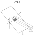
- FIGS. 1 and 2 there is shown an illustration for a vertically polarized wave directional gain decreasing due to the slope of an antenna.
- a front glass 12 on which a planar antenna 10 is formed is vertical
- an essential effective aperture area of the planar antenna for a vertically polarized wave propagating in a horizontal direction is assumed to be S.
- the front glass 12 is sloped, assuming that an angle of slope (an angle of slope from a vertical directional) is ⁇ , the effective aperture area in a horizontal direction becomes S ⁇ cos ⁇ .
- An object of the present invention is to provide a ground wave reception antenna unit which does not cause a decrease in a directional gain during the reception of a vertically polarized wave even when an antenna is positioned inclining from a vertical direction.
- Another object of the present invention is to provide a gain adjustment method for improving a directional gain at the time of a vertical polarized wave reception when an antenna is positioned inclining from a vertical direction.
- the present invention uses a reflector positioned in a horizontal direction or inclining from the horizontal direction by a predetermined angle for an antenna positioned with being inclined so as to increase an effective aperture area of the antenna to a vertically polarized wave propagating in a horizontal direction, thereby improving a directional gain of the antenna. Moreover, a horizontal directional characteristic improved in this way becomes almost non-directional.
- a first aspect of the present invention is a ground wave reception antenna unit comprising a planar antenna for receiving a vertically polarized wave propagating in a horizontal direction, the antenna being positioned inclining from a vertical direction, and a reflector positioned in a horizontal direction or inclining from the horizontal direction by a predetermined angle with being spaced from the planner antenna by a predetermined distance.
- the predetermined angle is 0-30°, more preferably is 6°.
- the reflector is either positioned in close proximity to the planar antenna or is positioned such that a predetermined distance between the planar antenna and the reflector is integer multiples of 0.5 ⁇ , herein ⁇ is a wavelength of a ground wave received by the planar antenna.
- a second aspect of the present invention is a method for regulating a directional gain of a planar antenna in a ground wave reception antenna unit for receiving a vertical polarized wave propagating in a horizontal direction, the planar antenna being positioned inclining from a vertical direction, the method comprising the steps of positioning a reflector in a horizontal direction or with inclining from the horizontal direction by a predetermined angle while spacing the reflector from the planner antenna by a predetermined distance, and selecting the predetermined distance so that the directional gain is improved, comparing to a case where the reflector is not provided.
- the reflector is either positioned in close proximity to the planar antenna or is positioned such that a predetermined distance between the planar antenna and the reflector is integer multiples of 0.5 ⁇ , herein ⁇ is a wave length of the ground wave received by the planar antenna.
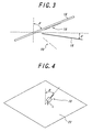
- FIG. 3 shows one embodiment of a ground wave reception antenna unit of the present invention.
- a planar antenna 10 is provided on a glass plate 16 which is sloped by an angle of ⁇ from a vertical direction.
- the glass plate corresponds to a front glass or rear glass.
- This ground wave reception antenna unit comprises a reflector positioned under the planar antenna 10, the reflector extending in a horizontal direction or inclining by an angle of ⁇ (0 - 30°) from a horizontal direction with being spaced from the planar antenna.
- the reflector is positioned inclining from a horizontal direction by 6°.
- a reflected image antenna 20 is formed by the reflector 18 positioned inclining from a horizontal direction, and an effective aperture area for a vertically polarized wave propagating in a horizontal direction apparently increases from S ⁇ cos ⁇ , In this way, a directional gain for a vertically polarized wave in a horizontal direction is improved.
- the reflector positioned described above has no portion to interrupt an emission characteristic in a horizontal direction, it is possible to make a vertically polarized wave directional gain in a horizontal direction thus obtained non-directional.
- the inventors of the present application have made simulation experiments to see how gain improvement effects will be changed by a distance L between the reflector 18 and the planar antenna 10. Note that the distance L is measured in a vertical direction from the lower end of the planar antenna to the reflector 18.
- FIG. 4 shows an arrangement of the planar antenna 10 and a reflector (an infinite plane) 22 for performing a correlation estimate (simulation) between the reflector distance L and a gain improvement effect.
- the angle ⁇ of inclination of the planar antenna 10 is selected to 60°.
- the reflector 22 is positioned inclining from a horizontal direction by 6°.
- FIG. 5 there is shown an estimation result as to how a gain improvement effect is obtained by placing the reflector in comparison with a state where no reflector is available.
- the abscissas shows the reflector distance L represented by a wavelength ⁇ of a received radio wave, and the ordinate shows an average gain variation (dB). From this correlation estimate, it is clear that, when the reflector distance L is 0 or 0.5 ⁇ , the gain improvement effect takes the maximal value. Further, it is clear that, when the reflector distance L is 0, i.e., the reflector is placed directly under the antenna (but the reflector is not in contact with the antenna), the improvement level is about 5 dB, resulting in the maximum effect.
- the reflector it is suitable for the reflector to be positioned directly under the antenna or arranged at a position of 0.5 ⁇ spaced from the antenna.
- FIG. 6 shows a pattern of the planar antenna 30 of a monopole type having a resonance frequency of 1.7 GHz.
- This planar antenna 30 is formed on a square glass plate 32, and comprises a rectangular ground conductor 34 and an elongated radiating element 36. Feeding points 38, 39 are provided and connected to the radiating element and ground conductor, respectively.
- FIG. 7 there is shown a constitution in which such an antenna is positioned inclining by 66° from a vertical direction and a reflector 40 is positioned inclining by 6° from a horizontal direction.
- the radiating element 36 is positioned in proximity of the reflector 40 as shown in FIG. 7 or the ground conductor 34 is positioned in proximity of the reflector 40 depends on the position where the planar antenna is provided on a window glass of a vehicle, for example.
- FIG. 8 there is shown such an example that a planar antenna 44 in which the ground conductor 34 is positioned in proximity to the reflector 40.
- the distance L is a length from the lower end of the ground conductor 34 to the reflector 40.
- the average gain is -7 dB where the reflector is not used, and 1 dB where the reflector is used. It is clear that, by using the reflector, the directional gain of the horizontal direction vertical polarized wave is improved by 8 dB on an average. It is also clear that a favorable characteristic of a non-directionality is obtained.
- the above-described planar antenna is provided on the inner surface of a sloped window glass (for example, a front glass or a rear glass) of a vehicle, and the reflector is positioned under this planar antenna.
- a sloped window glass for example, a front glass or a rear glass
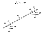
- FIG. 10 shows the positions where the antenna unit of the present embodiment may be provided on the front glass 42 of a vehicle.
- the radiating element 36 is positioned in proximity to the reflector 40
- the ground conductor 34 is positioned in proximity to the reflector 40.
- ground conductor 34 is easily connected to a body portion of a vehicle on the upper inside portion or lower inside portion of the front glass 42, since a body portion of a vehicle works as an earth conductor.
- a reflected image antenna is formed by a reflector positioned in a horizontal direction or inclining from a horizontal direction by a predetermined angle, and, in this way, an antenna effective aperture area for a vertical polarized wave propagating in a horizontal direction can be increased.
- a ground wave reception antenna unit may be implemented in which the directional gain during the reception of a vertically polarized wave does not decrease.
Landscapes
- Aerials With Secondary Devices (AREA)
- Variable-Direction Aerials And Aerial Arrays (AREA)
Abstract
A ground wave reception antenna unit is provided, in which a directional gain during the reception of a vertically polarized wave does not decrease. The antenna unit comprises a planar antenna positioned inclining from a vertical direction and a reflector positioned in a horizontal direction or inclining from a horizontal direction by a predetermined angle with being spaced from the planar antenna by a predetermined distance. The reflector is positioned in close proximity to the planar antenna, or is positioned at a distance of integer multiples of 0.5 lambda , wherein lambda is a wavelength of a ground wave received by the planar antenna. <IMAGE>
Description
The present invention relates generally to a ground wave
reception antenna unit and a method for adjusting a gain of the
antenna unit, particularly to a ground wave reception antenna unit
comprising an antenna body positioned inclining from a vertical
direction and a method for adjusting a gain of such an antenna unit.
There are some cases where an antenna body has to be
positioned inclining from a vertical direction in view of
circumstances where an antenna unit for receiving a wave
(a vertically polarized wave) from a ground-based station is
provided. One example is the case where a glass antenna for a
vehicle is provided. Particularly, the slope of a front glass, a rear
glass or the like of a vehicle is large so that the antenna body
positioned on the glass is inevitably inclined.
In such a case, when a vertically polarized wave
propagating in a horizontal direction is to be received, there is a
problem in that a directional gain of an antenna tends to decrease,
since an effective aperture area of the antenna decreases due to the
slope of the antenna.
In FIGS. 1 and 2, there is shown an illustration for a
vertically polarized wave directional gain decreasing due to the
slope of an antenna. As shown in FIG. 1, where a front glass 12
on which a planar antenna 10 is formed is vertical, an essential
effective aperture area of the planar antenna for a vertically
polarized wave propagating in a horizontal direction is assumed to
be S. Actually, as shown in FIG. 2, since the front glass 12 is
sloped, assuming that an angle of slope (an angle of slope from a
vertical directional) is , the effective aperture area in a horizontal
direction becomes S × cos . In this way, even if the essential
effective aperture area is S, when the antenna is inclined by , the
effective aperture area for a vertically polarized wave in a
horizontal direction becomes small such as S × cos . Thus, a
vertically polarized wave directional gain decreases in a horizontal
direction.
An object of the present invention is to provide a ground
wave reception antenna unit which does not cause a decrease in a
directional gain during the reception of a vertically polarized wave
even when an antenna is positioned inclining from a vertical
direction.
Another object of the present invention is to provide a
gain adjustment method for improving a directional gain at the
time of a vertical polarized wave reception when an antenna is
positioned inclining from a vertical direction.
The present invention uses a reflector positioned in a
horizontal direction or inclining from the horizontal direction by a
predetermined angle for an antenna positioned with being inclined
so as to increase an effective aperture area of the antenna to a
vertically polarized wave propagating in a horizontal direction,
thereby improving a directional gain of the antenna. Moreover, a
horizontal directional characteristic improved in this way becomes
almost non-directional.
A first aspect of the present invention is a ground wave
reception antenna unit comprising a planar antenna for receiving a
vertically polarized wave propagating in a horizontal direction, the
antenna being positioned inclining from a vertical direction, and a
reflector positioned in a horizontal direction or inclining from the
horizontal direction by a predetermined angle with being spaced
from the planner antenna by a predetermined distance.
The predetermined angle is 0-30°, more preferably is 6°.
As a result of experiments, it has been understood that a
directional gain is improved in a range of 0-30° and a maximum
directional gain is obtained at 6°.
In this ground wave reception antenna unit, the reflector
is either positioned in close proximity to the planar antenna or is
positioned such that a predetermined distance between the planar
antenna and the reflector is integer multiples of 0.5λ, herein λ is a
wavelength of a ground wave received by the planar antenna.
A second aspect of the present invention is a method for
regulating a directional gain of a planar antenna in a ground wave
reception antenna unit for receiving a vertical polarized wave
propagating in a horizontal direction, the planar antenna being
positioned inclining from a vertical direction, the method
comprising the steps of positioning a reflector in a horizontal
direction or with inclining from the horizontal direction by a
predetermined angle while spacing the reflector from the planner
antenna by a predetermined distance, and selecting the
predetermined distance so that the directional gain is improved,
comparing to a case where the reflector is not provided.
In this gain adjustment method, the reflector is either
positioned in close proximity to the planar antenna or is positioned
such that a predetermined distance between the planar antenna and
the reflector is integer multiples of 0.5λ, herein λ is a wave length
of the ground wave received by the planar antenna.
FIG. 3 shows one embodiment of a ground wave reception
antenna unit of the present invention. A planar antenna 10 is
provided on a glass plate 16 which is sloped by an angle of from
a vertical direction. In the case where the antenna unit is
mounted on a vehicle, the glass plate corresponds to a front glass
or rear glass.
This ground wave reception antenna unit comprises a
reflector positioned under the planar antenna 10, the reflector
extending in a horizontal direction or inclining by an angle of δ
(0 - 30°) from a horizontal direction with being spaced from the
planar antenna. In this embodiment, the reflector is positioned
inclining from a horizontal direction by 6°. A reflected image
antenna 20 is formed by the reflector 18 positioned inclining from
a horizontal direction, and an effective aperture area for a
vertically polarized wave propagating in a horizontal direction
apparently increases from S × cos , In this way, a directional
gain for a vertically polarized wave in a horizontal direction is
improved.
Further, since the reflector positioned described above
has no portion to interrupt an emission characteristic in a
horizontal direction, it is possible to make a vertically polarized
wave directional gain in a horizontal direction thus obtained non-directional.
The inventors of the present application have made
simulation experiments to see how gain improvement effects will
be changed by a distance L between the reflector 18 and the planar
antenna 10. Note that the distance L is measured in a vertical
direction from the lower end of the planar antenna to the reflector
18.
FIG. 4 shows an arrangement of the planar antenna 10 and
a reflector (an infinite plane) 22 for performing a correlation
estimate (simulation) between the reflector distance L and a gain
improvement effect. The angle of inclination of the planar
antenna 10 is selected to 60°. The reflector 22 is positioned
inclining from a horizontal direction by 6°.
In FIG. 5, there is shown an estimation result as to how a
gain improvement effect is obtained by placing the reflector in
comparison with a state where no reflector is available.
The abscissas shows the reflector distance L represented by a
wavelength λ of a received radio wave, and the ordinate shows an
average gain variation (dB). From this correlation estimate, it is
clear that, when the reflector distance L is 0 or 0.5λ, the gain
improvement effect takes the maximal value. Further, it is clear
that, when the reflector distance L is 0, i.e., the reflector is placed
directly under the antenna (but the reflector is not in contact with
the antenna), the improvement level is about 5 dB, resulting in the
maximum effect.
Hence, it is suitable for the reflector to be positioned
directly under the antenna or arranged at a position of 0.5λ spaced
from the antenna.
Further, estimating a vertically polarized wave average
gain for the larger distance L, it is appreciated that maximal values
are obtained at positions of integer multiples of 0.5λ, and these
maximal value decreases as the distance L becomes larger. It is
also possible, therefore, that the reflector is placed at positions of
integer multiples of 0.5λ.
As an example, the case of improving a directional gain
in the planar antenna of a monopole type formed on a glass surface
will now be described.
FIG. 6 shows a pattern of the planar antenna 30 of a
monopole type having a resonance frequency of 1.7 GHz. This
planar antenna 30 is formed on a square glass plate 32, and
comprises a rectangular ground conductor 34 and an elongated
radiating element 36. Feeding points 38, 39 are provided and
connected to the radiating element and ground conductor,
respectively.
In FIG. 7, there is shown a constitution in which such an
antenna is positioned inclining by 66° from a vertical direction and
a reflector 40 is positioned inclining by 6° from a horizontal
direction.
Whether the radiating element 36 is positioned in
proximity of the reflector 40 as shown in FIG. 7 or the ground
conductor 34 is positioned in proximity of the reflector 40 depends
on the position where the planar antenna is provided on a window
glass of a vehicle, for example. In FIG. 8, there is shown such an
example that a planar antenna 44 in which the ground conductor 34
is positioned in proximity to the reflector 40. In this case, the
distance L is a length from the lower end of the ground conductor
34 to the reflector 40.
For the antenna unit in which the reflector 40 is
positioned in close proximity to the lower end of the earth
conductor 34 in the antenna unit of FIG. 7 and the antenna unit in
which the reflector 40 is not provided in FIG. 7, a comparison
result of respective horizontal direction vertical polarized wave
directional gains is shown in FIG. 9.
The average gain is -7 dB where the reflector is not used,
and 1 dB where the reflector is used. It is clear that, by using the
reflector, the directional gain of the horizontal direction vertical
polarized wave is improved by 8 dB on an average. It is also
clear that a favorable characteristic of a non-directionality is
obtained.
Hence, in the case where such an antenna unit is mounted
on a vehicle, the above-described planar antenna is provided on the
inner surface of a sloped window glass (for example, a front glass
or a rear glass) of a vehicle, and the reflector is positioned under
this planar antenna.
FIG. 10 shows the positions where the antenna unit of the
present embodiment may be provided on the front glass 42 of a
vehicle. In the case where the antenna unit is attached to the
upper inside portion of the front glass 42, the radiating element 36
is positioned in proximity to the reflector 40, and in the case where
an antenna unit is attached to the lower inside portion of the front
glass 42, the ground conductor 34 is positioned in proximity to the
reflector 40.
The reason why such an arrangement is carried out is that
the ground conductor 34 is easily connected to a body portion of a
vehicle on the upper inside portion or lower inside portion of the
front glass 42, since a body portion of a vehicle works as an earth
conductor.
According to the present invention, a reflected image
antenna is formed by a reflector positioned in a horizontal
direction or inclining from a horizontal direction by a
predetermined angle, and, in this way, an antenna effective
aperture area for a vertical polarized wave propagating in a
horizontal direction can be increased. Hence, even when an
antenna body is inclined, a large directional gain can be obtained
for the vertical polarized wave propagating in a horizontal
direction. Therefore, even when an antenna body is positioned
inclining from a vertical direction, a ground wave reception
antenna unit may be implemented in which the directional gain
during the reception of a vertically polarized wave does not
decrease. Furthermore, a directional gain adjusting method for
improving a directional gain during the reception of a vertically
polarized wave when an antenna body is positioned inclining from
a vertical direction.
Claims (14)
- A ground wave reception antenna unit, comprising:a planar antenna for receiving a vertically polarized wave propagating in a horizontal direction, said antenna being positioned inclining from a vertical direction; anda reflector positioned in a horizontal direction or inclining from the horizontal direction by a predetermined angle with being spaced from said planner antenna by a predetermined distance.
- The ground wave reception antenna unit according to claim 1, wherein said reflector is positioned in close proximity to said planar antenna.
- The ground wave reception antenna unit according to claim 1, wherein a distance between said planar antenna and said reflector is integer multiples of 0.5λ, λ being a wave length of the ground wave received by said planar antenna.
- The ground wave reception antenna unit according to claim 1, wherein said predetermined angle is 0-30°.
- The ground wave reception antenna unit according to claim 4, wherein said determined angle is 6°.
- The ground wave reception antenna unit according to any one of claims 1 to 5, wherein said planar antenna is positioned on an inner surface of a front glass or rear glass of a vehicle and said reflector is positioned under said planar antenna.
- The ground wave reception antenna unit according to claim 6, wherein said planar antenna includes a radiating element and ground conductor positioned on the inner surface of the front glass or rear glass of a vehicle.
- A method for regulating a directional gain of a planar antenna in a ground wave reception antenna unit for receiving a vertical polarized wave propagating in a horizontal direction, said planar antenna being positioned inclining from a vertical direction, said method comprising the steps of:positioning a reflector in a horizontal direction or with inclining from the horizontal direction by a predetermined angle while spacing said reflector from said planner antenna by a predetermined distance, andselecting said predetermined distance so that the directional gain is improved, comparing to a case where said reflector is not provided.
- The method according to claim 8, wherein said step of selecting said predetermined distance includes a step of positioning said reflector in close proximity to said planar antenna.
- The method according to claim 8, wherein said step of selecting said predetermined distance includes selecting a predetermined distance between said planar antenna and said reflector to be integer multiples of 0.5λ, λ being a wave length of the ground wave received by said planar antenna.
- The method according to claim 8, wherein said predetermined angle is 0-30°.
- The method according to claim 11, wherein said predetermined angle is 6°.
- The method according to any one of claims 8-12, wherein said planar antenna is positioned on an inner surface of a front glass or rear glass of a vehicle.
- The method according to claim 13, wherein said planar antenna includes a radiating element and ground conductor positioned on the inner surface of the front glass or rear glass of a vehicle.
Applications Claiming Priority (3)
| Application Number | Priority Date | Filing Date | Title |
|---|---|---|---|
| JP2002169467 | 2002-06-11 | ||
| JP2002169467 | 2002-06-11 | ||
| PCT/JP2003/007415 WO2004004069A1 (en) | 2002-06-11 | 2003-06-11 | Terrestrial wave receiving antenna device and antenna gain adjusting method |
Publications (2)
| Publication Number | Publication Date |
|---|---|
| EP1548880A1 true EP1548880A1 (en) | 2005-06-29 |
| EP1548880A4 EP1548880A4 (en) | 2005-11-09 |
Family
ID=29996448
Family Applications (1)
| Application Number | Title | Priority Date | Filing Date |
|---|---|---|---|
| EP03733363A Withdrawn EP1548880A4 (en) | 2002-06-11 | 2003-06-11 | Terrestrial wave receiving antenna device and antenna gain adjusting method |
Country Status (4)
| Country | Link |
|---|---|
| US (1) | US20050174289A1 (en) |
| EP (1) | EP1548880A4 (en) |
| JP (1) | JPWO2004004069A1 (en) |
| WO (1) | WO2004004069A1 (en) |
Cited By (1)
| Publication number | Priority date | Publication date | Assignee | Title |
|---|---|---|---|---|
| CN102394378A (en) * | 2011-11-01 | 2012-03-28 | 东南大学 | High-gain vertical polarized all-metal sector antenna |
Families Citing this family (2)
| Publication number | Priority date | Publication date | Assignee | Title |
|---|---|---|---|---|
| US8011104B2 (en) * | 2006-04-10 | 2011-09-06 | The Gillette Company | Cutting members for shaving razors |
| US8499462B2 (en) * | 2006-04-10 | 2013-08-06 | The Gillette Company | Cutting members for shaving razors |
Family Cites Families (11)
| Publication number | Priority date | Publication date | Assignee | Title |
|---|---|---|---|---|
| JP2538329B2 (en) * | 1988-02-23 | 1996-09-25 | 三洋電機株式会社 | Antenna device |
| JPH02253702A (en) * | 1989-03-28 | 1990-10-12 | Japan Radio Co Ltd | Microstrip antenna |
| GB2235590B (en) * | 1989-08-21 | 1994-05-25 | Radial Antenna Lab Ltd | Planar antenna |
| JP2593899Y2 (en) * | 1992-02-05 | 1999-04-19 | 日本板硝子株式会社 | Automotive window glass antenna device |
| US5568156A (en) * | 1992-10-09 | 1996-10-22 | Asahi Glass Company Ltd. | High frequency wave glass antenna for an automobile |
| JPH07273526A (en) * | 1994-03-30 | 1995-10-20 | Nippon Sheet Glass Co Ltd | Car window glass antenna |
| JP3285299B2 (en) * | 1995-09-13 | 2002-05-27 | シャープ株式会社 | Compact antenna, optical beacon, radio beacon shared front end |
| US5734350A (en) * | 1996-04-08 | 1998-03-31 | Xertex Technologies, Inc. | Microstrip wide band antenna |
| DE19841187C1 (en) * | 1998-09-09 | 2000-02-10 | Hirschmann Richard Gmbh Co | Automobile mobile radio antenna e.g. for car mobile telephone, has reflector screening passenger compartment from electromagnetic radsiation provided by at least one monopole positioned adjacent automobile windscreen |
| EP1351335A1 (en) * | 2000-12-07 | 2003-10-08 | Asahi Glass Company Ltd. | Antenna device |
| US6919853B2 (en) * | 2002-03-04 | 2005-07-19 | M/A-Com, Inc. | Multi-band antenna using an electrically short cavity reflector |
-
2003
- 2003-06-11 EP EP03733363A patent/EP1548880A4/en not_active Withdrawn
- 2003-06-11 US US10/516,398 patent/US20050174289A1/en not_active Abandoned
- 2003-06-11 JP JP2004517253A patent/JPWO2004004069A1/en active Pending
- 2003-06-11 WO PCT/JP2003/007415 patent/WO2004004069A1/en not_active Ceased
Cited By (2)
| Publication number | Priority date | Publication date | Assignee | Title |
|---|---|---|---|---|
| CN102394378A (en) * | 2011-11-01 | 2012-03-28 | 东南大学 | High-gain vertical polarized all-metal sector antenna |
| CN102394378B (en) * | 2011-11-01 | 2014-01-22 | 东南大学 | High-gain vertical polarized all-metal sector antenna |
Also Published As
| Publication number | Publication date |
|---|---|
| WO2004004069A1 (en) | 2004-01-08 |
| JPWO2004004069A1 (en) | 2005-11-04 |
| US20050174289A1 (en) | 2005-08-11 |
| EP1548880A4 (en) | 2005-11-09 |
Similar Documents
| Publication | Publication Date | Title |
|---|---|---|
| Schlub et al. | Switched parasitic antenna on a finite ground plane with conductive sleeve | |
| US8174450B2 (en) | Broadband micropatch antenna system with reduced sensitivity to multipath reception | |
| US20090322642A1 (en) | Resonant cap loaded high gain patch antenna | |
| JPH10294614A (en) | Cellular antenna | |
| EP1365475B1 (en) | Multi-band antenna using an electrically short cavity reflector | |
| US7205953B2 (en) | Directional antenna array | |
| US6025803A (en) | Low profile antenna assembly for use in cellular communications | |
| WO2015125426A1 (en) | Collective antenna device | |
| KR20020024762A (en) | Planar antenna device | |
| US7268733B2 (en) | High frequency glass antenna for automobiles | |
| KR20170120032A (en) | Directional antenna module | |
| JP3464639B2 (en) | Multi-frequency antenna | |
| US12294144B2 (en) | Antenna device for vehicle | |
| US20050174289A1 (en) | Terrestrial wave receiving antenna device and antenna gain adjusting method | |
| EP1494317B1 (en) | Vehicle-mounted slot antenna | |
| US6930645B2 (en) | Automotive on-board antenna | |
| JP3793110B2 (en) | Monopole antenna with conductor reflector | |
| Padhi et al. | Parametric study of a microstrip Yagi antenna | |
| EP1434303A2 (en) | On-board antenna | |
| US7579991B2 (en) | Portable wireless apparatus | |
| US20250007172A1 (en) | Radiation pattern adaptable by obstacle bias | |
| KR102273252B1 (en) | Intelligent sensor mounted antenna for parking management | |
| JP4738967B2 (en) | Circularly polarized loop antenna | |
| WO2025218241A1 (en) | Vehicle | |
| JP3359491B2 (en) | Omnidirectional antenna |
Legal Events
| Date | Code | Title | Description |
|---|---|---|---|
| PUAI | Public reference made under article 153(3) epc to a published international application that has entered the european phase |
Free format text: ORIGINAL CODE: 0009012 |
|
| 17P | Request for examination filed |
Effective date: 20041208 |
|
| AK | Designated contracting states |
Kind code of ref document: A1 Designated state(s): AT BE BG CH CY CZ DE DK EE ES FI FR GB GR HU IE IT LI LU MC NL PT RO SE SI SK TR |
|
| A4 | Supplementary search report drawn up and despatched |
Effective date: 20050922 |
|
| STAA | Information on the status of an ep patent application or granted ep patent |
Free format text: STATUS: THE APPLICATION HAS BEEN WITHDRAWN |
|
| 18W | Application withdrawn |
Effective date: 20060523 |