EP1548859B1 - Batteriepack und Verfahren zu dessen Herstellung - Google Patents
Batteriepack und Verfahren zu dessen Herstellung Download PDFInfo
- Publication number
- EP1548859B1 EP1548859B1 EP20050006747 EP05006747A EP1548859B1 EP 1548859 B1 EP1548859 B1 EP 1548859B1 EP 20050006747 EP20050006747 EP 20050006747 EP 05006747 A EP05006747 A EP 05006747A EP 1548859 B1 EP1548859 B1 EP 1548859B1
- Authority
- EP
- European Patent Office
- Prior art keywords
- battery pack
- supports
- cell
- cells
- terminals
- Prior art date
- Legal status (The legal status is an assumption and is not a legal conclusion. Google has not performed a legal analysis and makes no representation as to the accuracy of the status listed.)
- Expired - Lifetime
Links
- 238000000034 method Methods 0.000 title claims description 14
- 239000012530 fluid Substances 0.000 claims description 7
- 239000003792 electrolyte Substances 0.000 claims description 5
- 238000004519 manufacturing process Methods 0.000 claims description 2
- 239000012212 insulator Substances 0.000 description 3
- 238000007792 addition Methods 0.000 description 1
- 230000004075 alteration Effects 0.000 description 1
- OJIJEKBXJYRIBZ-UHFFFAOYSA-N cadmium nickel Chemical compound [Ni].[Cd] OJIJEKBXJYRIBZ-UHFFFAOYSA-N 0.000 description 1
- 239000003990 capacitor Substances 0.000 description 1
- 238000001816 cooling Methods 0.000 description 1
- 239000012809 cooling fluid Substances 0.000 description 1
- 238000010168 coupling process Methods 0.000 description 1
- 238000005859 coupling reaction Methods 0.000 description 1
- 238000005520 cutting process Methods 0.000 description 1
- 238000010586 diagram Methods 0.000 description 1
- 239000011152 fibreglass Substances 0.000 description 1
- 239000003292 glue Substances 0.000 description 1
- 238000003780 insertion Methods 0.000 description 1
- 230000037431 insertion Effects 0.000 description 1
- 230000003993 interaction Effects 0.000 description 1
- 239000007788 liquid Substances 0.000 description 1
- 239000000463 material Substances 0.000 description 1
- 229910052987 metal hydride Inorganic materials 0.000 description 1
- 238000012544 monitoring process Methods 0.000 description 1
- 230000035939 shock Effects 0.000 description 1
- 238000003466 welding Methods 0.000 description 1
Images


Classifications
-
- H—ELECTRICITY
- H01—ELECTRIC ELEMENTS
- H01M—PROCESSES OR MEANS, e.g. BATTERIES, FOR THE DIRECT CONVERSION OF CHEMICAL ENERGY INTO ELECTRICAL ENERGY
- H01M10/00—Secondary cells; Manufacture thereof
- H01M10/60—Heating or cooling; Temperature control
- H01M10/64—Heating or cooling; Temperature control characterised by the shape of the cells
- H01M10/643—Cylindrical cells
-
- H—ELECTRICITY
- H01—ELECTRIC ELEMENTS
- H01M—PROCESSES OR MEANS, e.g. BATTERIES, FOR THE DIRECT CONVERSION OF CHEMICAL ENERGY INTO ELECTRICAL ENERGY
- H01M10/00—Secondary cells; Manufacture thereof
- H01M10/60—Heating or cooling; Temperature control
- H01M10/61—Types of temperature control
- H01M10/613—Cooling or keeping cold
-
- H—ELECTRICITY
- H01—ELECTRIC ELEMENTS
- H01M—PROCESSES OR MEANS, e.g. BATTERIES, FOR THE DIRECT CONVERSION OF CHEMICAL ENERGY INTO ELECTRICAL ENERGY
- H01M10/00—Secondary cells; Manufacture thereof
- H01M10/60—Heating or cooling; Temperature control
- H01M10/62—Heating or cooling; Temperature control specially adapted for specific applications
- H01M10/623—Portable devices, e.g. mobile telephones, cameras or pacemakers
- H01M10/6235—Power tools
-
- H—ELECTRICITY
- H01—ELECTRIC ELEMENTS
- H01M—PROCESSES OR MEANS, e.g. BATTERIES, FOR THE DIRECT CONVERSION OF CHEMICAL ENERGY INTO ELECTRICAL ENERGY
- H01M10/00—Secondary cells; Manufacture thereof
- H01M10/60—Heating or cooling; Temperature control
- H01M10/65—Means for temperature control structurally associated with the cells
- H01M10/656—Means for temperature control structurally associated with the cells characterised by the type of heat-exchange fluid
- H01M10/6561—Gases
-
- H—ELECTRICITY
- H01—ELECTRIC ELEMENTS
- H01M—PROCESSES OR MEANS, e.g. BATTERIES, FOR THE DIRECT CONVERSION OF CHEMICAL ENERGY INTO ELECTRICAL ENERGY
- H01M50/00—Constructional details or processes of manufacture of the non-active parts of electrochemical cells other than fuel cells, e.g. hybrid cells
- H01M50/20—Mountings; Secondary casings or frames; Racks, modules or packs; Suspension devices; Shock absorbers; Transport or carrying devices; Holders
- H01M50/204—Racks, modules or packs for multiple batteries or multiple cells
- H01M50/207—Racks, modules or packs for multiple batteries or multiple cells characterised by their shape
- H01M50/213—Racks, modules or packs for multiple batteries or multiple cells characterised by their shape adapted for cells having curved cross-section, e.g. round or elliptic
-
- Y—GENERAL TAGGING OF NEW TECHNOLOGICAL DEVELOPMENTS; GENERAL TAGGING OF CROSS-SECTIONAL TECHNOLOGIES SPANNING OVER SEVERAL SECTIONS OF THE IPC; TECHNICAL SUBJECTS COVERED BY FORMER USPC CROSS-REFERENCE ART COLLECTIONS [XRACs] AND DIGESTS
- Y02—TECHNOLOGIES OR APPLICATIONS FOR MITIGATION OR ADAPTATION AGAINST CLIMATE CHANGE
- Y02E—REDUCTION OF GREENHOUSE GAS [GHG] EMISSIONS, RELATED TO ENERGY GENERATION, TRANSMISSION OR DISTRIBUTION
- Y02E60/00—Enabling technologies; Technologies with a potential or indirect contribution to GHG emissions mitigation
- Y02E60/10—Energy storage using batteries
Definitions
- US5096788 describes a battery pack having a plurality of cells, an insulator and shock pads for protecting the cells.
- an improved battery pack is employed.
- the battery pack includes a first cell having top and bottom terminals, a first support disposed on the top terminal, and a second support disposed on the bottom terminal.
- At least one of the first and second supports may include a rib for maintaining the first cell in place.
- the rib may extend along a longitudinal axis of the first cell and/or extend substantially perpendicularly from the at least one of the first and second supports.
- the first and second supports may lock together.
- the first support may include a first protrusion
- the second support may include a second protrusion which engages the first protrusion.
- the battery pack may also include a pad disposed on at least one of the top and bottom terminals. The pad may be substantially circular.
- the battery pack may also include a second cell disposed between the first and second supports. The second cell may be disposed adjacent and/or separate to the first cell.
- the battery pack may also include a lead plate connecting the first and second cells.
- Battery cells 21 are coupled between the battery terminals POS and NEG.
- a temperature sensing device such as a negative temperature co-efficient (NTC) resistor, or thermistor, R T .
- the temperature sensing device R T is preferably in close physical proximity to the cells 21 for monitoring of the battery temperature.
- NTC negative temperature co-efficient
- other components such as capacitors, etc., or circuits can be used to provide a signal representative of the battery temperature.
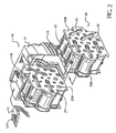
- the battery pack 10 comprises at least one packet 20, as shown in FIGS. 1-3.
- Packet 20 may comprise at least one cell 21, and preferably a plurality of cells 21.
- Each cell 21 has a positive terminal 21 P and a negative terminal 21 N.
- the packet 20 can then be inserted into battery pack housing 11.
- housing 11 has ribs 11R to guide insertion of packet 20 into housing 11 and/or to maintain packet 20 in place.
- FIG. 2 shows a clamshell housing 11, which includes two halves, and that one of the halves is not shown. Nevertheless, persons skilled in the art will know to provide the second half, and to fixedly attach both halves together via screws, snap-lock junctions, glue, etc.
- the packet 20 is preferably connected to terminal block 12, which is also disposed in housing 11.
- Terminal block 12 may have multiple terminals 12T, which may correspond to terminals POS, NEG, ID and/or TEMP. If multiple packets 20 are installed within housing 11, the packets 20 need to be electrically connected to each other via wires, lead plates, pressure connectors, etc., and/or to terminal block 12.
- supports 22T, 22B may also have holes 22H, which allow a fluid, either liquid or gaseous, such as air, to flow therethrough.
- ribs 22R are preferably used to maintain cells 21 separated. The fluid can thus flow into packet 20 through a support 22 via holes 22H, between cells 21, and out of packet 20 via holes 22H on the other support 22.
- Persons skilled in the art are referred to US Application No. 09/035,586, filed March 5, 1998 , entitled "Battery Cooling System”.
- housing 11 is provided with holes 13, for letting air into housing 11 (airflow AIN), which flows through packets 20 as explained above, and out of housing 11 (airflow AOUT), as shown in FIG. 3.
- airflow AIN airflow AIN
- the air may enter through the top of battery pack 10 and exit through holes 13.
Landscapes
- Chemical & Material Sciences (AREA)
- Chemical Kinetics & Catalysis (AREA)
- Electrochemistry (AREA)
- General Chemical & Material Sciences (AREA)
- Engineering & Computer Science (AREA)
- Manufacturing & Machinery (AREA)
- Life Sciences & Earth Sciences (AREA)
- Biophysics (AREA)
- Battery Mounting, Suspending (AREA)
Claims (28)
- Batterieeinheit (10) mit
einer Ober- und Unterkontakte aufweisenden ersten Zelle (21),
einer auf dem Oberkontakt angeordneten ersten Abstützung (22T) und
einer auf dem Unterkontakt angeordneten zweiten Abstützung (22B), dadurch gekennzeichnet, dass die Batterieeinheit ferner ein absorbierendes Kissen (24) zum Absorbieren von Elektrolyt aufweist, das an zumindest einem von dem Ober- oder dem Unterkontakt angeordnet ist. - Batterieeinheit nach Anspruch 1, bei der zumindest eine von den ersten und zweiten Abstützungen ferner eine Rippe (22R) zum Haltern der ersten Zelle an ihrer Stelle aufweist.
- Batterieeinheit nach Anspruch 2, bei der sich die Rippe entlang einer Längsachse der ersten Zelle erstreckt.
- Batterieeinheit nach Anspruch 2, bei der die Rippe sich im Wesentlichen senkrecht von zumindest einer der ersten und zweiten Abstützungen erstreckt.
- Batterieeinheit nach einem der vorhergehenden Ansprüche, bei der sich eine Längsachse der ersten Zelle im Wesentlichen senkrecht zu zumindest einer der ersten und zweiten Abstützungen erstreckt.
- Batterieeinheit nach einem der vorhergehenden Ansprüche, wobei die erste und die zweite Abstützung sich miteinander verriegeln.
- Batterieeinheit nach einem der vorhergehenden Ansprüche, wobei die erste Abstützung einen ersten Vorsprung (25) aufweist und die zweite Abstützung einen zweiten Vorsprung (26), der mit dem ersten Vorsprung in Eingriff kommt.
- Batterieeinheit nach einem der vorhergehenden Ansprüche, bei der das Kissen im Wesentlichen kreisförmig ist.
- Batterieeinheit nach einem der vorhergehenden Ansprüche, bei der ein Radius des Kissens im Wesentlichen gleich oder kleiner als der Radius der ersten Zelle ist.
- Batterieeinheit nach einem der vorhergehenden Ansprüche, ferner aufweisend eine zwischen den ersten und zweiten Abstützungen vorgesehene zweite Zelle.
- Batterieeinheit nach Anspruch 10, bei der die zweite Zelle benachbart zur ersten Zelle angeordnet ist.
- Batterieeinheit nach Anspruch 10, bei der die zweite Zelle von der ersten Zelle getrennt ist.
- Batterieeinheit nach einem der Ansprüche 10 bis 12, ferner aufweisend eine die ersten und zweiten Zellen verbindende Leiterplatte (23).
- Batterieeinheit nach Anspruch 13, bei der die Leiterplatte die ersten und zweiten Zellen durch eine der ersten und zweiten Abstützungen verbindet.
- Batterieeinheit nach einem der vorhergehenden Ansprüche, bei der zumindest eine der ersten und zweiten Abstützungen ein Loch (22H) zum Durchtritt von Fluid aufweist.
- Batterieeinheit nach Anspruch 15, bei der das Fluid Luft ist.
- Batterieeinheit nach einem der vorhergehenden Ansprüche, ferner aufweisend ein die erste Zelle und die ersten und zweiten Abstützungen halterndes Gehäuse (11).
- Batterieeinheit nach Anspruch 17, ferner aufweisend eine zweite Zelle mit Ober- und Unterkontakten,
eine auf dem Oberkontakt der zweiten Zelle vorgesehene dritte Abstützung und
eine auf dem Unterkontakt der zweiten Zelle vorgesehene vierte Abstützung,
wobei sich die zweite Zelle und die dritten und vierten Abstützungen im Gehäuse befinden. - Batterieeinheit nach Anspruch 17, ferner aufweisend mit der ersten Zelle verbundene erste und zweite Batteriekontakte.
- Batterieeinheit nach Anspruch 17, bei der das Gehäuse mindestens ein Loch (13) für den Durchtritt von Fluid aufweist.
- Batterieeinheit nach Anspruch 20, bei der das Fluid Luft ist.
- Verfahren zum Herstellen einer Batterieeinheit (10) umfassend:Zurverfügungstellen von ersten (22T) und zweiten (22B) Abstützungen und ersten und zweiten Zellen (21), wobei die ersten und zweiten Zellen Ober- und Unterkontakte aufweisen,Anordnen der ersten und zweiten Zellen zwischen den ersten und zweiten Abstützungen, wobei die Ober- und Unterkontakte der ersten und zweiten Zellen eine der te der ersten und zweiten Zellen eine der ersten und zweiten Abstützungen berühren, dadurch gekennzeichnet, dass das Verfahren ferner den Schritt des Bereitstellenes eines absorbierenden Kissens (24) zum Absorbieren von Elektrolyt zwischen einem von dem Oberkontakt und dem Unterkontakt der ersten Zelle und von einer aus der ersten und der zweiten Abstützung aufweist.
- Verfahren nach Anspruch 22, ferner umfassend das Verbinden der ersten und zweiten Zellen mit einer Leiterplatte (23).
- Verfahren nach Anspruch 23, bei dem die Leiterplatte die ersten und zweiten Zellen durch eine der ersten und zweiten Abstützungen verbindet.
- Verfahren nach einem der Ansprüche 22 bis 24, ferner ein Verriegeln der ersten und zweiten Abstützungen miteinander umfassend.
- Verfahren nach einem der Ansprüche 22 bis 25, ferner umfassend ein Einsetzen der ersten und zweiten Abstützungen und der ersten und zweiten Zellen in ein Gehäuse (11).
- Verfahren nach Anspruch 26, ferner umfassend:Zurverfügungstellen von dritten und vierten Abstützungen und dritten und vierten Zellen, wobei die dritten und vierten Zellen Ober- und Unterkontakte haben,Anordnen der ersten und vierten Zellen zwischen den dritten und vierten Abstützungen, wobei jeder der Ober- und Unterkontakte der dritten und vierten Zellen eine der dritten und vierten Abstützungen berührt, undAnordnen der dritten und vierten Zellen und der dritten und vierten Abstützungen im Gehäuse.
- Verfahren nach Anspruch 26, ferner umfassend
Zurverfügungstellen von ersten und zweiten Batteriekontakten und
elektrisches Verbinden der ersten und zweiten Batteriekontakte mit den ersten und zweiten Zellen.
Applications Claiming Priority (3)
| Application Number | Priority Date | Filing Date | Title |
|---|---|---|---|
| US14401899P | 1999-07-15 | 1999-07-15 | |
| US144018P | 1999-07-15 | ||
| EP20000306010 EP1069631B1 (de) | 1999-07-15 | 2000-07-14 | Batteriepack und Verfahren zu dessen Herstellung |
Related Parent Applications (1)
| Application Number | Title | Priority Date | Filing Date |
|---|---|---|---|
| EP20000306010 Division EP1069631B1 (de) | 1999-07-15 | 2000-07-14 | Batteriepack und Verfahren zu dessen Herstellung |
Publications (3)
| Publication Number | Publication Date |
|---|---|
| EP1548859A2 EP1548859A2 (de) | 2005-06-29 |
| EP1548859A3 EP1548859A3 (de) | 2005-11-09 |
| EP1548859B1 true EP1548859B1 (de) | 2007-06-13 |
Family
ID=34553498
Family Applications (1)
| Application Number | Title | Priority Date | Filing Date |
|---|---|---|---|
| EP20050006747 Expired - Lifetime EP1548859B1 (de) | 1999-07-15 | 2000-07-14 | Batteriepack und Verfahren zu dessen Herstellung |
Country Status (1)
| Country | Link |
|---|---|
| EP (1) | EP1548859B1 (de) |
Cited By (3)
| Publication number | Priority date | Publication date | Assignee | Title |
|---|---|---|---|---|
| EP2945205B1 (de) | 2014-05-12 | 2017-10-18 | LG Electronics Inc. | Staubsauger |
| EP3799193A1 (de) * | 2019-09-30 | 2021-03-31 | Makita Corporation | Batteriepack |
| US12300833B2 (en) | 2019-09-30 | 2025-05-13 | Makita Corporation | Battery pack |
Families Citing this family (6)
| Publication number | Priority date | Publication date | Assignee | Title |
|---|---|---|---|---|
| EP1927147B1 (de) * | 2005-09-20 | 2016-12-14 | Metabowerke GmbH | Akkupack sowie elektrohandwerkzeuggerät |
| EP2006054A1 (de) * | 2007-06-22 | 2008-12-24 | Metabowerke GmbH | Vorrichtung zur Halterung von Akkuzellen bei Akkupack |
| DE102007031860A1 (de) | 2007-07-09 | 2009-01-15 | Robert Bosch Gmbh | Akkumulator |
| DE102010010844A1 (de) * | 2010-03-10 | 2011-09-15 | Bayerische Motoren Werke Aktiengesellschaft | Speichermodul zur Spannungsversorgung insbesondere eines Kraftfahrzeugs |
| DE102012110644A1 (de) * | 2012-11-07 | 2014-05-08 | Bmz Batterien-Montage-Zentrum Gmbh | Elektrisches Energiespeichermodul |
| CN105538242A (zh) * | 2015-12-31 | 2016-05-04 | 宁波中旺工具有限公司 | 一种电动螺丝刀 |
Family Cites Families (5)
| Publication number | Priority date | Publication date | Assignee | Title |
|---|---|---|---|---|
| US3219485A (en) * | 1962-12-21 | 1965-11-23 | Union Carbide Corp | Portable power pack of rechargeable alkaline batteries |
| US4806440A (en) * | 1987-02-05 | 1989-02-21 | Cni | Lantern battery substitute |
| US5096788A (en) * | 1990-10-05 | 1992-03-17 | Motorola, Inc. | Weldless battery pack |
| US5756229A (en) * | 1996-12-17 | 1998-05-26 | Wilson Greatbatch Ltd. | Electrochemical cell having mechanical shock tolerance |
| US6168883B1 (en) * | 1997-10-15 | 2001-01-02 | Eveready Battery Company, Inc. | Prismatic electrochemical cell and battery |
-
2000
- 2000-07-14 EP EP20050006747 patent/EP1548859B1/de not_active Expired - Lifetime
Non-Patent Citations (1)
| Title |
|---|
| None * |
Cited By (4)
| Publication number | Priority date | Publication date | Assignee | Title |
|---|---|---|---|---|
| EP2945205B1 (de) | 2014-05-12 | 2017-10-18 | LG Electronics Inc. | Staubsauger |
| EP2945205B2 (de) † | 2014-05-12 | 2022-04-27 | LG Electronics Inc. | Staubsauger |
| EP3799193A1 (de) * | 2019-09-30 | 2021-03-31 | Makita Corporation | Batteriepack |
| US12300833B2 (en) | 2019-09-30 | 2025-05-13 | Makita Corporation | Battery pack |
Also Published As
| Publication number | Publication date |
|---|---|
| EP1548859A2 (de) | 2005-06-29 |
| EP1548859A3 (de) | 2005-11-09 |
Similar Documents
| Publication | Publication Date | Title |
|---|---|---|
| EP1069631B1 (de) | Batteriepack und Verfahren zu dessen Herstellung | |
| US7189473B2 (en) | Battery venting system | |
| US20260094887A1 (en) | Battery pack for a cordless power tool | |
| US5466545A (en) | Compact, shock resistant battery pack | |
| EP2919295B1 (de) | Verfahren zum anordnen die komponenten eines batteriepacks | |
| US5096788A (en) | Weldless battery pack | |
| US5298347A (en) | Battery pack | |
| EP1139483B1 (de) | Flüssiggekühltes batteriesatzsystem | |
| JP4610362B2 (ja) | パック電池 | |
| CN114600306B (zh) | 电池组及电气设备 | |
| CN101326656A (zh) | 用于制备电池模块的组合式间隔件 | |
| JP2005056721A (ja) | パック電池 | |
| EP1548859B1 (de) | Batteriepack und Verfahren zu dessen Herstellung | |
| US5212020A (en) | Battery case | |
| KR102942290B1 (ko) | 셀 모듈 어셈블리 및 이를 포함하는 배터리 팩 | |
| CN201048152Y (zh) | 用于无塞绳电动装置的充电器系统 | |
| US4217400A (en) | Rechargeable electrochemical cell pack having overcurrent protection | |
| US20210242440A1 (en) | Lithium ion battery and enclosure | |
| JP2005317457A (ja) | パック電池 | |
| US20220115714A1 (en) | Battery pack | |
| JP4610316B2 (ja) | パック電池 | |
| US20220115749A1 (en) | Battery pack | |
| JP2003323870A (ja) | 電池パック | |
| JP3604829B2 (ja) | パック電池 | |
| JPH07262977A (ja) | パック電池 |
Legal Events
| Date | Code | Title | Description |
|---|---|---|---|
| PUAI | Public reference made under article 153(3) epc to a published international application that has entered the european phase |
Free format text: ORIGINAL CODE: 0009012 |
|
| 17P | Request for examination filed |
Effective date: 20050329 |
|
| AC | Divisional application: reference to earlier application |
Ref document number: 1069631 Country of ref document: EP Kind code of ref document: P |
|
| AK | Designated contracting states |
Kind code of ref document: A2 Designated state(s): AT BE CH CY DE DK ES FI FR GB GR IE IT LI LU MC NL PT SE |
|
| RIN1 | Information on inventor provided before grant (corrected) |
Inventor name: GROSSMANN, HORST Inventor name: ZEMLOCK, MICHAEL A. Inventor name: BRADUS, ROBERT Inventor name: AGAN, KEVIN S. |
|
| PUAL | Search report despatched |
Free format text: ORIGINAL CODE: 0009013 |
|
| AK | Designated contracting states |
Kind code of ref document: A3 Designated state(s): AT BE CH CY DE DK ES FI FR GB GR IE IT LI LU MC NL PT SE |
|
| RIC1 | Information provided on ipc code assigned before grant |
Ipc: 7H 01M 2/10 A |
|
| AKX | Designation fees paid |
Designated state(s): AT BE CH CY DE DK ES FI FR GB GR IE IT LI LU MC NL PT SE |
|
| GRAP | Despatch of communication of intention to grant a patent |
Free format text: ORIGINAL CODE: EPIDOSNIGR1 |
|
| GRAS | Grant fee paid |
Free format text: ORIGINAL CODE: EPIDOSNIGR3 |
|
| GRAA | (expected) grant |
Free format text: ORIGINAL CODE: 0009210 |
|
| AC | Divisional application: reference to earlier application |
Ref document number: 1069631 Country of ref document: EP Kind code of ref document: P |
|
| AK | Designated contracting states |
Kind code of ref document: B1 Designated state(s): AT BE CH CY DE DK ES FI FR GB GR IE IT LI LU MC NL PT SE |
|
| PG25 | Lapsed in a contracting state [announced via postgrant information from national office to epo] |
Ref country code: CH Free format text: LAPSE BECAUSE OF FAILURE TO SUBMIT A TRANSLATION OF THE DESCRIPTION OR TO PAY THE FEE WITHIN THE PRESCRIBED TIME-LIMIT Effective date: 20070613 Ref country code: LI Free format text: LAPSE BECAUSE OF FAILURE TO SUBMIT A TRANSLATION OF THE DESCRIPTION OR TO PAY THE FEE WITHIN THE PRESCRIBED TIME-LIMIT Effective date: 20070613 |
|
| REG | Reference to a national code |
Ref country code: GB Ref legal event code: FG4D |
|
| REG | Reference to a national code |
Ref country code: CH Ref legal event code: EP |
|
| REG | Reference to a national code |
Ref country code: IE Ref legal event code: FG4D |
|
| REF | Corresponds to: |
Ref document number: 60035228 Country of ref document: DE Date of ref document: 20070726 Kind code of ref document: P |
|
| REG | Reference to a national code |
Ref country code: SE Ref legal event code: TRGR |
|
| ET | Fr: translation filed | ||
| REG | Reference to a national code |
Ref country code: ES Ref legal event code: FG2A Ref document number: 2285595 Country of ref document: ES Kind code of ref document: T3 |
|
| PG25 | Lapsed in a contracting state [announced via postgrant information from national office to epo] |
Ref country code: AT Free format text: LAPSE BECAUSE OF FAILURE TO SUBMIT A TRANSLATION OF THE DESCRIPTION OR TO PAY THE FEE WITHIN THE PRESCRIBED TIME-LIMIT Effective date: 20070613 |
|
| NLV1 | Nl: lapsed or annulled due to failure to fulfill the requirements of art. 29p and 29m of the patents act | ||
| REG | Reference to a national code |
Ref country code: CH Ref legal event code: PL |
|
| PG25 | Lapsed in a contracting state [announced via postgrant information from national office to epo] |
Ref country code: BE Free format text: LAPSE BECAUSE OF FAILURE TO SUBMIT A TRANSLATION OF THE DESCRIPTION OR TO PAY THE FEE WITHIN THE PRESCRIBED TIME-LIMIT Effective date: 20070613 |
|
| PG25 | Lapsed in a contracting state [announced via postgrant information from national office to epo] |
Ref country code: PT Free format text: LAPSE BECAUSE OF FAILURE TO SUBMIT A TRANSLATION OF THE DESCRIPTION OR TO PAY THE FEE WITHIN THE PRESCRIBED TIME-LIMIT Effective date: 20071113 Ref country code: NL Free format text: LAPSE BECAUSE OF FAILURE TO SUBMIT A TRANSLATION OF THE DESCRIPTION OR TO PAY THE FEE WITHIN THE PRESCRIBED TIME-LIMIT Effective date: 20070613 |
|
| PLBE | No opposition filed within time limit |
Free format text: ORIGINAL CODE: 0009261 |
|
| STAA | Information on the status of an ep patent application or granted ep patent |
Free format text: STATUS: NO OPPOSITION FILED WITHIN TIME LIMIT |
|
| PG25 | Lapsed in a contracting state [announced via postgrant information from national office to epo] |
Ref country code: MC Free format text: LAPSE BECAUSE OF NON-PAYMENT OF DUE FEES Effective date: 20070731 Ref country code: DK Free format text: LAPSE BECAUSE OF FAILURE TO SUBMIT A TRANSLATION OF THE DESCRIPTION OR TO PAY THE FEE WITHIN THE PRESCRIBED TIME-LIMIT Effective date: 20070613 Ref country code: GR Free format text: LAPSE BECAUSE OF FAILURE TO SUBMIT A TRANSLATION OF THE DESCRIPTION OR TO PAY THE FEE WITHIN THE PRESCRIBED TIME-LIMIT Effective date: 20070914 |
|
| 26N | No opposition filed |
Effective date: 20080314 |
|
| PG25 | Lapsed in a contracting state [announced via postgrant information from national office to epo] |
Ref country code: IE Free format text: LAPSE BECAUSE OF NON-PAYMENT OF DUE FEES Effective date: 20070716 |
|
| PGFP | Annual fee paid to national office [announced via postgrant information from national office to epo] |
Ref country code: ES Payment date: 20080728 Year of fee payment: 9 |
|
| PGFP | Annual fee paid to national office [announced via postgrant information from national office to epo] |
Ref country code: FR Payment date: 20080729 Year of fee payment: 9 Ref country code: IT Payment date: 20080724 Year of fee payment: 9 |
|
| PG25 | Lapsed in a contracting state [announced via postgrant information from national office to epo] |
Ref country code: FI Free format text: LAPSE BECAUSE OF FAILURE TO SUBMIT A TRANSLATION OF THE DESCRIPTION OR TO PAY THE FEE WITHIN THE PRESCRIBED TIME-LIMIT Effective date: 20070613 |
|
| PG25 | Lapsed in a contracting state [announced via postgrant information from national office to epo] |
Ref country code: CY Free format text: LAPSE BECAUSE OF FAILURE TO SUBMIT A TRANSLATION OF THE DESCRIPTION OR TO PAY THE FEE WITHIN THE PRESCRIBED TIME-LIMIT Effective date: 20070613 |
|
| PG25 | Lapsed in a contracting state [announced via postgrant information from national office to epo] |
Ref country code: LU Free format text: LAPSE BECAUSE OF NON-PAYMENT OF DUE FEES Effective date: 20070714 |
|
| REG | Reference to a national code |
Ref country code: FR Ref legal event code: ST Effective date: 20100331 |
|
| PG25 | Lapsed in a contracting state [announced via postgrant information from national office to epo] |
Ref country code: FR Free format text: LAPSE BECAUSE OF NON-PAYMENT OF DUE FEES Effective date: 20090731 |
|
| REG | Reference to a national code |
Ref country code: ES Ref legal event code: FD2A Effective date: 20090715 |
|
| PG25 | Lapsed in a contracting state [announced via postgrant information from national office to epo] |
Ref country code: ES Free format text: LAPSE BECAUSE OF NON-PAYMENT OF DUE FEES Effective date: 20090715 |
|
| PG25 | Lapsed in a contracting state [announced via postgrant information from national office to epo] |
Ref country code: IT Free format text: LAPSE BECAUSE OF NON-PAYMENT OF DUE FEES Effective date: 20090714 |
|
| PGFP | Annual fee paid to national office [announced via postgrant information from national office to epo] |
Ref country code: DE Payment date: 20130729 Year of fee payment: 14 Ref country code: SE Payment date: 20130729 Year of fee payment: 14 |
|
| PGFP | Annual fee paid to national office [announced via postgrant information from national office to epo] |
Ref country code: GB Payment date: 20130729 Year of fee payment: 14 |
|
| REG | Reference to a national code |
Ref country code: DE Ref legal event code: R119 Ref document number: 60035228 Country of ref document: DE |
|
| REG | Reference to a national code |
Ref country code: SE Ref legal event code: EUG |
|
| GBPC | Gb: european patent ceased through non-payment of renewal fee |
Effective date: 20140714 |
|
| PG25 | Lapsed in a contracting state [announced via postgrant information from national office to epo] |
Ref country code: DE Free format text: LAPSE BECAUSE OF NON-PAYMENT OF DUE FEES Effective date: 20150203 |
|
| REG | Reference to a national code |
Ref country code: DE Ref legal event code: R119 Ref document number: 60035228 Country of ref document: DE Effective date: 20150203 |
|
| PG25 | Lapsed in a contracting state [announced via postgrant information from national office to epo] |
Ref country code: GB Free format text: LAPSE BECAUSE OF NON-PAYMENT OF DUE FEES Effective date: 20140714 Ref country code: SE Free format text: LAPSE BECAUSE OF NON-PAYMENT OF DUE FEES Effective date: 20140715 |